


 Loading...
Wisenet QNV-6032R, QNV-6072R, QNV-6012R, QNV-6022R, QND-6072R User Manual
...NETWORK CAMERA
User Manual
QND-6012R/6022R/6032R/6072R/6082R
QNV-6012R/6022R/6032R/6072R/6082R QNO-6012R/6022R/6032R/6072R/6082R

overview
IMPORTANT SAFETY INSTRUCTIONS
1.Read these instructions.
2.Keep these instructions.
3.Heed all warnings.
4.Follow all instructions.
5.Do not use this apparatus near water.
6.Clean the contaminated area on the product surface with a soft, dry cloth or a damp cloth.
(Do not use a detergent or cosmetic products that contain alcohol, solvents or surfactants or oil constituents as they may deform or cause damage to the product.)
7.Do not block any ventilation openings, Install in accordance with the manufacturer’s instructions.
8.Do not install near any heat sources such as radiators, heat registers, stoves, or other apparatus (including amplifiers) that produce heat.
9.Do not defeat the safety purpose of the polarized or grounding-type plug. A polarized plug has two blades with one wider than the other. A grounding type plug has two blades and a third grounding prong. The wide blade or the third prong are provided for your safety. If the provided plug does not fit into your outlet, consult an electrician for replacement of the obsolete outlet.
10.Protect the power cord from being walked on or pinched particularly at plugs, convenience receptacles, and the point where they exit from the apparatus.
11.Only use attachments/ accessories specified by the manufacturer.
12.Use only with the cart, stand, tripod, bracket, or table specified by the manufacturer, or sold with the apparatus. When a cart is used, use caution when moving the cart/ apparatus combination to avoid injury from tip-over.
13. Unplug this apparatus during lighting storms or when unused for long periods of time.
14. Refer all servicing to qualified service personnel. Servicing is required when the apparatus has been damaged in any way, such as power-supply cord or plug is damaged, liquid has
been spilled or objects have fallen into the apparatus, the apparatus has been exposed to rain or moisture, does not operate normally, or has been dropped.
15.This product is intended to be a Listed Power Supply Unit marked “Class2” or “LPS” and rated from 12Vdc, 0.55A or PoE(48V), 0.16A. (QND-6072R/6082R, QNV-6072R/6082R)
16.This product is intended to be a Listed Power Supply Unit marked “Class2” or “LPS” and rated from 12Vdc, 0.54A or PoE(48V), 0.16A. (QND-6012R/6022R/6032R, QNV-6012R/6022R/6032R)
17.This product is intended to be a Listed Power Supply Unit marked “Class2” or “LPS” and rated from 12Vdc, 0.55A or PoE(48V), 0.16A. (QNO-6072R/6082R)
18.This product is intended to be a Listed Power Supply Unit marked “Class2” or “LPS” and rated from 12Vdc, 0.51A or PoE(48V), 0.15A. (QNO-6012R/6022R/6032R)
19.This product is intended to be supplied by isolation power.
20.If you use excessive force when installing the product, the camera may be damaged and malfunction. If you forcibly install the product using non-compliant tools, the product may be damaged.
21.Do not install the product in a place where chemical substances or oil mist exists or may be generated. As edible oils such as soybean oil may damage or warp the product, do not install the product in the kitchen or near the kitchen table.
This may cause damage to the product.
22.When installing the product, be careful not to allow the surface of the product to be stained with chemical substance.
Some chemical solvents such as cleaner or adhesives may cause serious damage to the product’s surface.
23.If you install/disassemble the product in a manner that has not been recommended, the production functions/ performance may not be guaranteed.
Install the product by referring to “Installation & connection” in the user manual.
24.Installing or using the product in water can cause serious damage to the product.
25.Although a rapid change in temperature could cause frost inside the dome, there will be no problem with the video.
WARNING
TO REDUCE THE RISK OF FIRE OR ELECTRIC SHOCK, DO NOT EXPOSE THIS PRODUCT TO RAIN OR MOISTURE. DO NOT INSERT ANY METALLIC OBJECT THROUGH THE VENTILATION GRILLS OR OTHER OPENNINGS ON THE EQUIPMENT.
Apparatus shall not be exposed to dripping or splashing and that no objects filled with liquids, such as vases, shall be placed on the apparatus.
To prevent injury, this apparatus must be securely attached to the Wall/ceiling in accordance with the installation instructions.
CAUTION
CAUTION
RISK OF ELECTRIC SHOCK.
DO NOT OPEN
CAUTION : TO REDUCE THE RISK OF ELECTRIC SHOCK.
DO NOT REMOVE COVER (OR BACK).
NO USER SERVICEABLE PARTS INSIDE.
REFER SERVICING TO QUALIFIED SERVICE PERSONNEL.
EXPLANATION OF GRAPHICAL SYMBOLS
The lightning flash with arrowhead symbol, within an equilateral triangle, is intended to alert the user to the presence of “dangerous voltage” within the product’s enclosure that may be of sufficient magnitude to constitute a risk of electric shock to persons.
The exclamation point within an equilateral triangle is intended to alert the user to the presence of important operating and maintenance (servicing) instructions in the literature accompanying the product.
OVERVIEW ●●
English _3

overview
Class  construction
An apparatus with CLASS construction shall be connected to a MAINS socket outlet with a protective earthing connection.
Battery
Batteries(battery pack or batteries installed) shall not be exposed to excessive heat such as sunshine, fire or the like.
The battery cannot be replaced.
Disconnection Device
Disconnect the main plug from the apparatus, if it’s defected. And please call a repair man in your location.
When used outside of the U.S., it may be used HAR code with fittings of an approved agency is employed.
CAUTION
RISK OF EXPLOSION IF BATTERY IS REPLACED BY AN INCORRECT TYPE. DISPOSE OF USED BATTERIES ACCORDING TO THE INSTRUCTIONS.
ATTENTION
IL Y A RISQUE D’EXPLOSION SI LA BATTERIE EST REMPLACÉE PAR UNE BATTERIE DE TYPE INCORRECT.
METTRE AU REBUT LES BATTERIES USAGÉES CONFORMÉMENT AUX INSTRUCTIONS.
These servicing instructions are for use by qualified service personnel only.
To reduce the risk of electric shock do not perform any servicing other than that contained in the operating instructions unless you are qualified to do so.
Please use the input power with just one camera and other devices must not be connected.
The ITE is to be connected only to PoE networks without routing to the outside plant. The wired LAN hub providing power over the Ethernet (PoE) in accordance with IEEE 802-3af shall be a UL Listed device with the output evaluated as a Limited Power Source as defined in UL60950-1.
Unit is intended for installation in a Network Environment 0 as defined in IEC TR 62102. As such, associated Ethernet wiring shall be limited to inside the building.
Please read the following recommended safety precautions carefully.
yyDo not place this apparatus on an uneven surface.
yyDo not install on a surface where it is exposed to direct sunlight, near heating equipment or heavy cold area.
yyDo not place this apparatus near conductive material. yyDo not attempt to service this apparatus yourself. yyDo not place a glass of water on the product.
yyDo not install near any magnetic sources. yyDo not block any ventilation openings. yyDo not place heavy items on the product.
yyPlease wear protective gloves when installing/removing the camera. The high temperature of the product surface may cause a burn.
User’s Manual is a guidance book for how to use the products. The meaning of the symbols are shown below.
yyReference : In case of providing information for helping of product’s usages
yyNotice : If there’s any possibility to occur any damages for the goods and human caused by not following the instruction
Please read this manual for the safety before using of goods and keep it in the safe place.
WARNING
To Prevent damage which may caused by IR LED, don't stare at operating lamp. For below models only.
QND-6012R/6022R/6032R/6072R/6082R
QNV-6012R/6022R/6032R/6072R/6082R
QNO-6012R/6022R/6032R/6072R/6082R
Risk Group 1
WARNING IR emitted from this product. Do not stare at operating lamp.
Product tested against IEC 62471
4_ overview

CONTENTS
OVERVIEW
3
3 Important Safety Instructions
6 Product Features
6 Recommended PC Specifications
6 Recommended Micro SD/SDHC/SDXC Memory Card Specifications
6 NAS recommended specs
7 What’s Included
8 At a Glance (QND-6012R/6022R/6032R)
10 At a Glance (QND-6072R/6082R)
12 At a Glance (QNO-6012R/6022R/6032R/ 6072R/6082R)
14 At a Glance (QNV-6012R/6022R/6032R/ 6072R/6082R)
INSTALLATION & CONNECTION |
16 |
6072R/6082R) |
16 |
Installation (QND-6012R/6022R/6032R/ |
|
17 |
Installation (QNO-6012R/6022R/6032R/ |
|
18 |
6072R/6082R) |
|
Installation (QNV-6012R/6022R/6032R) |
||
|
20 |
Installation (QNV-6072R/6082R) |
|
23 |
Inserting/Removing a Micro SD Memory |
|
27 |
Card |
|
Powering and networking |
NETWORK CONNECTION AND SETUP
31
31 Connecting the Camera Directly to Local Area Networking
31 Connecting the Camera Directly to a DHCP Based DSL/Cable Modem
32 Buttons used in IP Installer
32 Static IP Setup
34 Dynamic IP Setup
34 Port Range Forward (Port Mapping) Setup
35 Connecting to the Camera from a Shared Local PC
35Connecting to the Camera from a Remote PC via the Internet
WEB VIEWER
36
APPENDIX
38
36 |
Connecting to the Camera |
37 |
Password setting |
37 |
Login |
37 |
Camera Web Viewer Setup |
38 |
Specification (QND-6012R/6022R/6032R, |
|
QNV-6012R/6022R/6032R, |
40 |
QNO-6012R/6022R/6032R) |
Specification (QND-6072R/6082R, |
|
42 |
QNV-6072R/6082R, QNO-6072R/6082R) |
Product Overview (QND-6012R/6022R/ |
|
43 |
6032R/6072R/6082R) |
Product Overview (QNO-6012R/6022R/ |
|
44 |
6032R/6072R/6082R) |
Product Overview (QNV-6012R/6022R/ |
|
45 |
6032R/6072R/6082R) |
Troubleshooting |
|
46 |
Open Source Announcement |
OVERVIEW ●●
English _5
overview
PRODUCT FEATURES
•• Dustproof/Waterproof (IP66) (QNV-6012R/6022R/6032R/6072R/6082R, QNO-6012R/6022R/6032R/6072R/6082R)
The dustproof and waterproof design makes you feel at ease when installing the product outdoors or exposing it to rain.
•• IR mode
If the IR indicator turns on, the product switches to the IR mode for preventing an object from being too bright, which helps you identify the object in near distance.
•• Supports 2 megapixel resolution videos
•• Multi-Streaming
This network camera can display videos in different resolutions and qualities simultaneously using different CODECs.
•• Web Browser-based Monitoring
Using the Internet web browser to display the image in a local network environment.
•• Alarm
When an event occurs, video is either sent to the email address registered by the user, sent to the FTP server, saved in a Micro SD card or NAS, or a signal is sent to the alert output terminal.
•• Tampering Detection
Detects tempering attempts on video monitoring.
•• Defocus detection function
Detects the defocus phenomenon of the camera lens.
•• Motion Detection
Detects motion from the camera’s video input.
•• Auto Detection of Disconnected Network
Detects network disconnection before triggering an event.
•• ONVIF Compliance
This product supports ONVIF Profile S&G. For more information, refer to www.onvif.org.
RECOMMENDED PC SPECIFICATIONS
•• CPU : Intel(R) Core(TM) i7 3.4 GHz or higher
•• RAM : 8G or higher
•• Supported OS : Windows 7, 8.1, 10, Mac OS X 10.12, 10.13, 10.14
•• Recommended browser : Google Chrome
•• Supported browsers : MS Explorer11, MS Edge, Mozilla Firefox(Window 64bit only), Apple Safari(Mac OS X only)
•• VGA : PCIe 256MB GDDR3 video graphics card or higher
Please see the appendix for detailed information on verified OS and browsers.
RECOMMENDED MICRO SD/SDHC/SDXC MEMORY CARD SPECIFICATIONS
•• Recommended capacity : 16GB ~ 128GB(MLC type)
•• Recommended Manufacturers : SanDisk, Transcend
•• Product Type : High endurance
•• The compatibility varies depending on the card manufacturers and types.
NAS RECOMMENDED SPECS
•• Recommended capacity : 200GB or higher is recommended.
•• Simultaneous access : One unit of NAS can accept a maximum of sixteen camera accesses.
•• For this camera, you are recommended to use a NAS with the following manufacturer’s specs.
Recommended products |
Available sizes |
QNAP NAS |
A maximum of 16 cameras can access simultaneously. |
Synology NAS |
A maximum of 16 cameras can access simultaneously. |
JJ`` If you use NAS equipment for purposes other than video saving, the number of accessible cameras may be reduced.
6_ overview
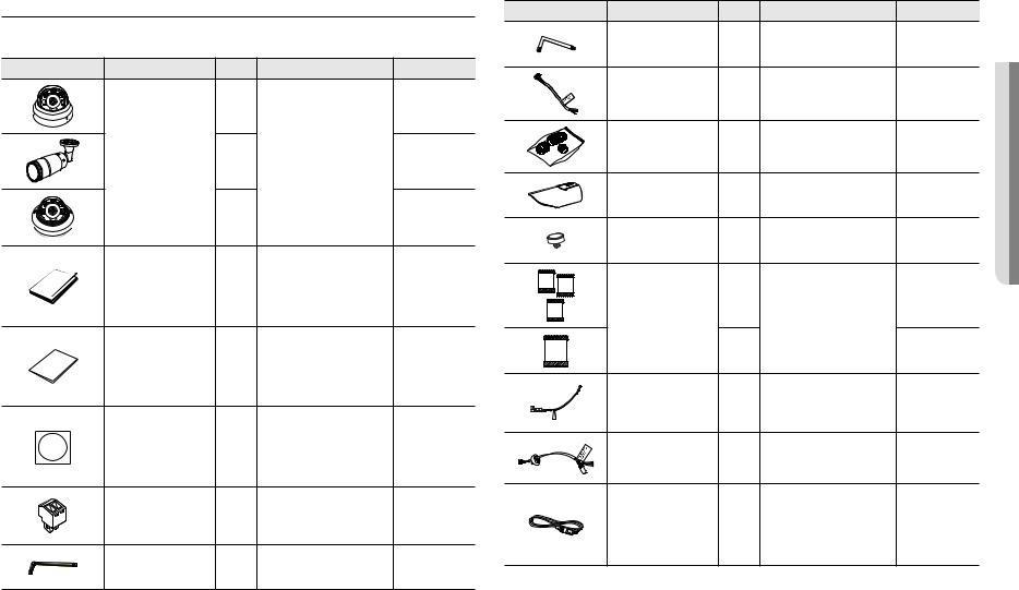
WHAT’S INCLUDED
Please check if your camera and accessories are all included in the product package. (As for each sales country, accessories are not the same.)
Appearance |
Item Name |
Quantity |
Description |
Model Name |
|
|
1 |
|
QND-6012R/6022R/ |
|
|
|
6032R/6072R/6082R |
|
|
|
|
|
|
|
Camera |
1 |
|
QNO-6012R/6022R/ |
|
|
6032R/6072R/6082R |
||
|
|
1 |
|
QNV-6012R/6022R/ |
|
|
|
6032R/6072R/6082R |
|
|
|
|
|
|
|
|
|
|
QND-6012R/6022R/ |
|
Quick Guide |
|
|
6032R/6072R/6082R, |
|
1 |
|
QNV-6012R/6022R/ |
|
|
(Optional) |
|
6032R/6072R/6082R, |
|
|
|
|
|
QNO-6012R/6022R/ |
|
|
|
|
6032R/6072R/6082R |
|
|
|
|
QND-6012R/6022R/ |
|
Warranty card |
|
|
6032R/6072R/6082R, |
|
1 |
|
QNV-6012R/6022R/ |
|
|
(Optional) |
|
6032R/6072R/6082R, |
|
|
|
|
|
QNO-6012R/6022R/ |
|
|
|
|
6032R/6072R/6082R |
|
|
|
|
QND-6012R/6022R/ |
|
|
|
|
6032R/6072R/6082R, |
|
Template |
1 |
Product installation guide |
QNV-6012R/6022R/ |
|
6032R/6072R/6082R, |
|||
|
|
|
|
QNO-6012R/6022R/ |
|
|
|
|
6032R/6072R/6082R |
|
|
|
|
QND-6012R/6022R/ |
|
Power Terminal Block |
1 |
Plugged in the power plug |
6032R/6072R/6082R, |
|
QNV-6012R/6022R/ |
|||
|
|
|
|
6032R/6072R/6082R |
|
L Wrench |
1 |
Used to control the direction of the |
QNO-6012R/6022R/ |
|
camera |
6032R/6072R/6082R |
||
|
|
|
Appearance |
Item Name |
Quantity |
Description |
Model Name |
|
L Wrench (star-shaped) |
1 |
Used to remove and replace the |
QNV-6012R/6022R/ |
|
dome cover |
6032R/6072R/6082R |
||
|
|
|
||
|
Alarm cable |
1 |
Used when connecting to an alarm |
QND-6012R/6022R/ |
|
6032R/6072R/6082R |
|||
|
|
|
|
|
|
RJ45 waterproof accessory |
1 |
Used to install in humid places |
QNO-6012R/6022R/ |
|
6032R/6072R/6082R |
|||
|
|
|
|
|
|
Sunshield |
1 |
It protects the camera from the |
QNO-6012R/6022R/ |
|
direct sunlight. |
6032R/6072R/6082R |
||
|
|
|
||
|
Sunshield Hold |
1 |
It fixes the sunshield with the camera. |
QNO-6012R/6022R/ |
|
6032R/6072R/6082R |
|||
|
|
3 |
|
QNO-6012R/6022R/ |
|
|
|
6032R/6072R/6082R |
|
|
Card-type moisture absorbent |
|
Attached when installed. |
|
|
|
|
||
|
|
1 |
|
QNV-6012R/6022R/ |
|
|
|
6032R/6072R/6082R |
|
|
|
|
|
|
|
|
|
|
QND-6012R/6022R/ |
|
Power Cable |
1 |
Used to plug into the power port |
6032R/6072R/6082R, |
|
QNV-6012R/6022R/ |
|||
|
|
|
|
6032R/6072R/6082R |
|
Audio/alarm cable |
1 |
Used to connect with the audio and |
QNV-6012R/6022R/ |
|
alarm port |
6032R/6072R/6082R |
||
|
|
|
||
|
|
|
|
QND-6012R/6022R/ |
|
|
|
Used to test the camera connection |
6032R/6072R/6082R, |
|
Cable for the testing monitor |
1 |
QNV-6012R/6022R/ |
|
|
to a portable display device |
6032R/6072R/6082R, |
||
|
|
|
|
QNO-6012R/6022R/ |
|
|
|
|
6032R/6072R/6082R |
OVERVIEW ●●
English _7
overview
Appearance |
Item Name |
Quantity |
Description |
Model Name |
|
Cable bush |
1 |
Used to connect the LAN cable |
QNV-6012R/6022R/ |
|
6032R/6072R/6082R |
|||
|
|
|
|
|
|
Cap Installer |
1 |
Used when connecting RJ45 cable |
QNV-6012R/6022R/ |
|
6032R/6072R/6082R |
|||
|
|
|
|
Optional Accessories for Installation
For your easier installation, you can purchase appropriate optional accessories available.
Model name |
Hanging Mount |
Back Box |
Pole Mount |
All |
QNV-6012R/6022R/6032R |
SBP-122HMW |
SBV-120GW |
|
SBP-300LMW |
|
(Parapet Mount) |
|||
|
|
|
|
SBP-300CMW |
QNV-6072R/6082R |
SBP-301HMW2 |
SBV-136BW |
|
|
|
(Ceiling Mount) |
|||
|
|
|
|
SBP-300WMW1 |
QND-6012R/6022R/6032R |
SBP-300HMW7 |
|
|
(Wall Mount) |
|
|
SBP-300NBW |
||
|
|
|
|
|
|
|
|
|
(Instalation Box) |
QND-6072R/6082R |
SBP-122HMW |
|
|
|
|
|
SBP-300PMW |
||
|
|
|
|
(Pole Mount) |
QNO-6012R/6022R/ |
|
|
|
|
|
SBO-100B1 |
SBP-302PM |
SBP-300KMW |
|
6032R/6072R/6082R |
|
|
|
(Corner Mount) |
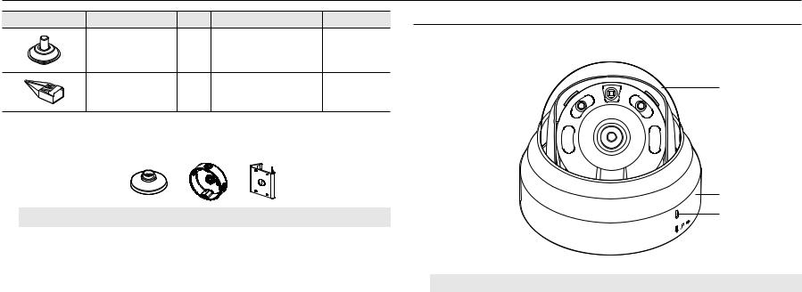
AT A GLANCE (QND-6012R/6022R/6032R)
Appearance
a
ET
b c
Item |
Description |
a Dome cover |
Case cover used to protect the lens and the main unit. |
|
|
b Camera Case |
Housing part that covers the camera body. |
c Microphone hole |
Microphone is embedded. |
8_ overview
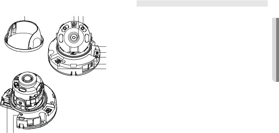
Components
a bcd
LINK |
|
|
|
|
NETWORK |
|
|
|
|
|
RESET |
|
e |
|
IN |
OUT |
VIDEO |
f |
|
|
.ALM |
|
GND |
g |
2 |
|
|||
|
|
5 |
|
|
|
|
4 |
|
|
FRONT |
|
|
|
|
DC12V |
|
|
|
h |
|
|
|
|
|
|
|
|
|
i |
|
FRONT |
|
|
DC |
12V |
ACT |
|
|
|
|
|
LINKKN |
|
|
j k
Item |
|
Description |
a Inside cover |
Protective cover for the main body. |
|
|
|
|
b Illumination Sensor |
Detects incoming light to control the IR LED. |
|
|
|
|
c Lens |
Lens for the camera. |
|
|
|
|
d IR LED |
These infrared LED’s are controlled by the illumination sensor. |
|
|
|
|
|
The button restores all camera settings to the factory default. |
|
|
Press and hold for about 5 seconds to reboot the system. |
|
e Reset Button |
J If you reset the camera, the network settings will be adjusted so that DHCP can be |
|
enabled. If there is no DHCP server in the network, you must run the IP Installer |
||
|
program to change the basic network settings such as IP address, Subnet mask, |
|
|
Gateway, etc., before you can connect to the network. |
|
f Test Monitor Out |
Output port for test monitoring the video output. Use the test monitor cable to connect to a |
|
mobile display and check the test video. |
||
g Alarm I/O Port |
ARM-IN |
Used to connect the alarm input sensor or external day/night sensor. |
ARM-OUT |
Used to connect the alarm output signal. |
|
|
GND |
These are common ports to connect alarm input/output signals. |
h Microphone hole |
Microphone is embedded. |
|
|
|
|
i Power Port |
Port for power terminal block. |
|
|
|
|
Micro SD Memory Card |
Compartment for the Micro SD memory card. |
|
j Compartment |
||
k Network Port |
Used to connect the PoE or Ethernet cable for network connection. |
|
|
|
|
OVERVIEW ●●
English _9
overview
AT A GLANCE (QND-6072R/6082R)
Appearance
a
b
c
Item |
Description |
a Dome cover |
Case cover used to protect the lens and the main unit. |
|
|
b Camera Case |
Housing part that covers the camera body. |
c Microphone hole |
Microphone is embedded. |
Components
a |
b c |
|||
|
|
|
|
|
|
|
|
|
|
|
|
|
|
|
d
ETWORKN
e
f
m l
|
|
N |
T |
|
|
|
W |
F |
|
|
|
AF |
|
|
VIDEO |
|
VIDEO |
|
|
|
RESET |
1,2ALARMIN/OUT |
RESET |
1,2ALARMIN/OUT |
|
|
|
||
kji |
|
|
|
h g |
n |
||
<QND-6072R> |
|
|
<QND-6082R> |
10_ overview
Item |
|
Description |
a Inside cover |
Protective cover for the main body. |
|
|
|
|
b Illumination Sensor |
Detects incoming light to control the IR LED. |
|
|
|
|
c Lens |
Lens for the camera. |
|
|
|
|
d IR LED |
These infrared LED’s are controlled by the illumination sensor. |
|
|
|
|
e Power Port |
Port for power terminal block. |
|
|
|
|
f Microphone hole |
Microphone is embedded. |
|
|
|
|
g Network Port |
Used to connect the PoE or Ethernet cable for network connection. |
|
|
|
|
Micro SD Memory Card |
Compartment for the Micro SD memory card. |
|
h Compartment |
||
i Alarm I/O Port |
ARM-IN |
Used to connect the alarm input sensor or external day/night sensor. |
ARM-OUT |
Used to connect the alarm output signal. |
|
|
GND |
These are common ports to connect alarm input/output signals. |
|
The button restores all camera settings to the factory default. |
|
|
Press and hold for about 5 seconds to reboot the system. |
|
j Reset Button |
J If you reset the camera, the network settings will be adjusted so that DHCP can be |
|
enabled. If there is no DHCP server in the network, you must run the IP Installer |
||
|
program to change the basic network settings such as IP address, Subnet mask, |
|
|
Gateway, etc., before you can connect to the network. |
|
k Test Monitor Out |
Output port for test monitoring the video output. Use the test monitor cable to connect to a |
|
mobile display and check the test video. |
||
Item |
|
Description |
l Zoom control lever |
T |
Zoom in (Tele) |
W |
Zoom out (Wide) |
|
(QND-6072R) |
|
|
Release the lever and |
move it to left or right to zoom the lens in or out. |
|
|
Turn the lever clockwise to fix the adjusted position to prevent it from being moved. |
|
m Focus control lever |
N |
Focusing on a near object (Near) |
F |
Focusing on a far object (Far) |
|
(QND-6072R) |
|
|
Release the lever and |
move it to left or right to adjust the lens focus. |
|
|
Turn the lever clockwise to fix the adjusted position to prevent it from being moved. |
|
|
T |
Zoom in (Tele) |
n (QNDZoom/Focus-6082R)Control Button |
W |
Zoom out (Wide) |
N |
Focusing on a near object (Near) |
|
|
F |
Focusing on a far object (Far) |
|
Focus Control |
Press this button for automatic focus control. |
OVERVIEW ●●
English _11
overview
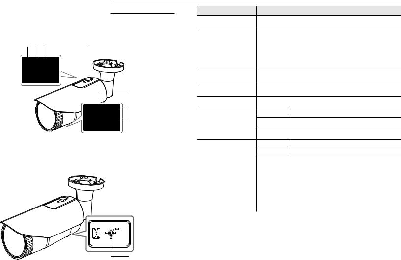
AT A GLANCE (QNO-6012R/6022R/6032R/6072R/6082R) |
|
Item |
Description |
|
Appearance |
|
|
a Micro SD card slot |
(Internal space of the product) This is a slot in which you can insert a Micro SD card. |
|
|
|
|
The button restores all camera settings to the factory default. |
a bc |
d |
|
|
Press and hold for about 5 seconds to reboot the system. |
|
b Reset Button |
J If you reset the camera, the network settings will be adjusted so that DHCP can be |
||
|
|
|
||
|
|
|
enabled. If there is no DHCP server in the network, you must run the IP Installer |
|
|
|
|
|
program to change the basic network settings such as IP address, Subnet mask, |
|
|
|
|
Gateway, etc., before you can connect to the network. |
|
|
|
c Test Monitor Out |
Output port for test monitoring the video output. Use the test monitor cable to connect to a |
|
|
|
mobile display and check the test video. |
|
|
|
e |
d Sunshield Hold |
It fixes the sunshield with the camera. |
|
|
e Sunshield |
|
|
|
|
|
It protects the camera from the direct sunlight. |
|
f |
T |
Zoom in (Tele) |
|
g |
|||
W |
Zoom out (Wide) |
||
f Zoom control lever |
|||
(QNO-6072R) |
Release the lever and move it to left or right to zoom the lens in or out. |
||
<QNO-6072R> |
Turn the lever clockwise to fix the adjusted position to prevent it from being moved. |
||
N |
Focusing on a near object (Near) |
||
g Focus control lever |
F |
Focusing on a far object (Far) |
|
(QNO-6072R) |
Release the lever and move it to left or right to adjust the lens focus. |
||
|
Turn the lever clockwise to fix the adjusted position to prevent it from being moved. |
||
|
|
|
|
|
T |
Zoom in (Tele) |
|
|
|
|
h (QNOZoom/Focus-6082R)Control Button |
W |
Zoom out (Wide) |
|
|
|
|
N |
Focusing on a near object (Near) |
|
|
|
|
|
|
F |
Focusing on a far object (Far) |
|
|
|
c |
|
Focus Control |
Press this button for automatic focus control. |
|
|
|
|
|||
|
|
|
||||
|
|
|
|
|
|
|
|
|
|
|
|
|
|
|
|
|
|
|
|
|
h
<QNO-6082R>
12_ overview
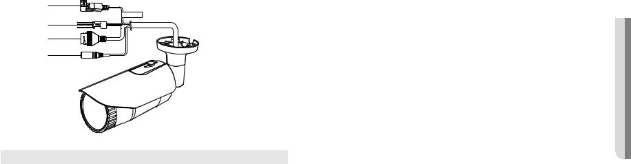
Components
a
CAUTION:Be ware of the Rated Voltage and Polarity of the power connection.
b c d
Item |
|
Description |
a Power Port |
Used to plug the power cable. |
|
|
|
|
b Alarm I/O Port |
ARM-OUT |
Used to connect the alarm output signal. |
GND |
These are common ports to connect alarm input/output signals. |
|
|
ARM-IN |
Used to connect the alarm input sensor or external day/night sensor. |
c Network Port |
Used to connect the PoE or Ethernet cable for network connection. |
|
|
|
|
d Audio In Jack |
Used to connect to a microphone. |
|
|
|
|
OVERVIEW ●●
English _13

overview
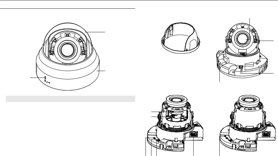
AT A GLANCE (QNV-6012R/6022R/6032R/6072R/6082R)
Appearance
a
b
Components
abc
1234567 |
d |
|
|
|
RESET |
e |
N |
F |
|
|
|
T |
|
|
VIDEO |
|
W |
AF |
VIDEO |
|
f |
|
|
|
|
g |
|
|
|
<QNV-6072R> |
|
<QNV-6082R> |
||
1234567
 RESET
RESET
l
Item |
Description |
|
a Dome cover |
Case cover used to protect the lens and the main unit. |
k |
b Camera Case |
|
|
Housing part that covers the camera body. |
j |
i h
<QNV-6072R>
14_ overview

Item |
|
Description |
|
a Illumination Sensor |
Detects incoming light to control the IR LED. |
||
|
|
||
b Lens |
Lens for the camera. |
||
|
|
|
|
c IR LED |
These infrared LED’s are controlled by the illumination sensor. |
||
|
|
|
|
|
ARM-IN |
Used to connect the alarm input sensor or external day/night sensor. |
|
d Audio and alarm cable port |
ARM-OUT |
Used to connect the alarm output signal. |
|
GND |
These are common ports to connect alarm input/output signals. |
||
|
|||
|
AUDIO IN |
Used to connect to a microphone. |
|
|
The button restores all camera settings to the factory default. |
||
|
Press and hold for about 5 seconds to reboot the system. |
||
e Reset Button |
J If you reset the camera, the network settings will be adjusted so that DHCP can be |
||
enabled. If there is no DHCP server in the network, you must run the IP Installer |
|||
|
program to change the basic network settings such as IP address, Subnet mask, |
||
|
Gateway, etc., before you can connect to the network. |
||
f Test Monitor Out |
Output port for test monitoring the video output. Use the test monitor cable to connect to a |
||
mobile display and check the test video. |
|||
g Power Port |
Port for power terminal block. |
||
|
|
||
h Network Port |
Used to connect the PoE or Ethernet cable for network connection. |
||
|
|
|
|
Micro SD Memory Card |
Compartment for the Micro SD memory card. |
||
i Compartment |
|||
j Zoom control lever |
T |
Zoom in (Tele) |
|
W |
Zoom out (Wide) |
||
(QNV-6072R) |
|
|
|
Release the |
lever and move it to left or right to zoom the lens in or out. |
||
|
Turn the lever clockwise to fix the adjusted position to prevent it from being moved. |
||
k Focus control lever |
N |
Focusing on a near object (Near) |
|
F |
Focusing on a far object (Far) |
||
(QNV-6072R) |
|
|
|
Release the |
lever and move it to left or right to adjust the lens focus. |
||
|
Turn the lever clockwise to fix the adjusted position to prevent it from being moved. |
||
Item |
|
Description |
|
T |
Zoom in (Tele) |
l Zoom/Focus Control Button |
W |
Zoom out (Wide) |
N |
Focusing on a near object (Near) |
|
(QNV-6082R) |
|
|
F |
Focusing on a far object (Far) |
|
|
Focus |
Press this button for automatic focus control. |
|
Control |
|
|
|
OVERVIEW ●●
English _15
installation & connection
INSTALLATION (QND-6012R/6022R/6032R/6072R/6082R)
Precautions before installation
Ensure you read out the following instructions before installing the camera:
•• It must be installed on the area (ceiling or wall) that can withstand 5 times the weight of the camera including the installation bracket.
•• Stuck-in or peeled-off cables can cause damage to the product or a fire.
•• For safety purposes, keep anyone else away from the installation site. And put aside personal belongings from the site, just in case.
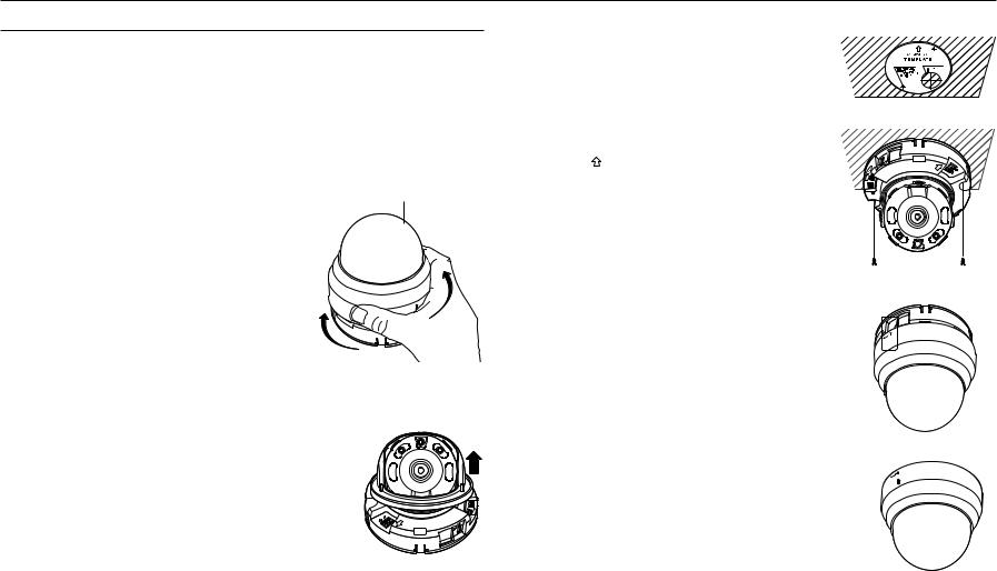
Disassembling
1. Use one hand to hold the camera’s bottom part and turn the cover |
Dome Cover |
counterclockwise with another hand to separate it. |
|
JJ`` Do not touch the transparent part of the dome cover once the protective |
|
film is removed. |
|
2. Lift up the inner cover to separate it.
FRONT
DC12V 
Installation
1. Consider the direction to be monitored, attach the template, and drill holes by following the template.
Ø 3.5 Screw - 2 Holes |
Ø 35 mm |
2.Using 2 tapping screws, fix the camera at 2 holes drilled with a template.
`` Set the < > mark imprinted on the camera to face the direction of camera monitoring.
3.Connect the camera internal terminal with the corresponding cable.
4.Adjust the lens in a desired direction by referring to the “Adjusting the monitoring direction for the camera” section. (page 23)
JJ`` We recommend you not to touch the lens as the camera lens has been properly focused in the final process of manufacturing. If so, the lens may be out of focus or stained by alien substances.
5.Please connect the inner cover to the main body.
6.While grabbing the bottom side of the camera with your hand, please grab and push its cover with the other hand to align the two arrow signs, as shown in the figure.
JJ`` To assemble the dome cover, make the arrows match each other and press the cover firmly.
If the dome cover is rotated during assembly or is assembled incorrectly, diffused reflection may occur or the lens section may rotate, which will cause the shooting range to be changed.
`` Make sure that the dome cover is correctly connected to the bottom part as shown in the figure.
If the snap-fit is not connected correctly, the dome cover may fall, which may cause injury.
 DC12V
DC12V
FRONT
RESET
NETWORK
LINK
16_ installation & connection
INSTALLATION (QNO-6012R/6022R/6032R/6072R/6082R)
JJ`` This camera is waterproof and in compliance with the IP66 spec, but the jack connected to the external cable is not. You are recommended to install this product below the edge of eaves to prevent the cable from being externally exposed.
Precautions before installation
Ensure you read out the following instructions before installing the camera:
•• It must be installed on the area (ceiling or wall) that can withstand 5 times the weight of the camera including the installation bracket.
•• Stuck-in or peeled-off cables can cause damage to the product or a fire.
•• For safety purposes, keep anyone else away from the installation site. And put aside personal belongings from the site, just in case.
•• Do not use the sunshield hole for any purpose other than for connecting the sunshield.
•• For the manual variable focal lens camera, features such as focus and zoom should be adjusted before installation.
When adjusting these, be sure to prevent foreign substances from becoming attached.
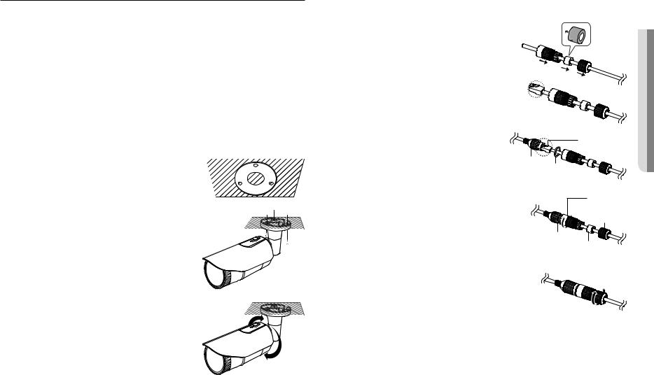
Installation |
|
1. Consider the direction to be monitored, attach the template, and |
Mounting Template |
drill holes by following the template. |
|
|
Cable Line |
2. Insert and fasten 3 tapping screws into 3 holes to secure the camera.
3. Connect the appropriate cables with camera terminals.
4. Adjust the camera direction using the L wrench provided.
JJ`` When you adjust the camera position using a bracket, please loosen the bracket screw, adjust the camera, and tighten it. If you attempt to adjust it forcibly while the screw is tight, it may result in a scratch or other problems.
How to connect the RJ45 waterproof cable to a LAN cable
1. Insert it through the arrow direction.
2.Connect the LAN connector (male) to the cable.
3.Connect the RJ45 modular jack (female) to the RJ45 connector (male).
JJ`` Please, keep each of the parts separated.
RJ45 connector (male)
RJ45 modular |
Rubber ring |
jack (female) |
4. Assemble by rotating the RJ45 modular jack (female) and the RJ45 |
RJ45 connector |
protection cover |
|
protection cover clockwise (Follow the arrow). |
Back cover |
|
Rubber ring |
|
Cable waterproof |
|
gasket |
5. Assemble by rotating RJ45 protection cover and back cover clockwise (Follow the arrow).
When the back cover is assembled, the cable waterproof gasket is tightly attached to the cable to make it waterproof.
JJ`` You must fully assemble it to rotate the back cover up to the end of the screw thread of the RJ45 connector.
CONNECTION & INSTALLATION ●●
English _17
installation & connection
Outdoor installation
When you install it outside of the building, please waterproof it with waterproof butyl rubber tape (can be |
|||||||||||||
purchased in stores) so that water does not leak from the gap of the cable connected to the outside. |
|
||||||||||||
1. |
Connect the power, I/O, AUDIO, and LAN cables. |
|
|
|
|
|
|
|
|
|
|
|
|
|
Camera |
|
|
|
|
|
|
|
|
|
System |
||
2. |
Wrap the black cable jacket (Area A) and the cable connection |
|
|
|
|
|
|
|
|
|
|
|
|
|
|
|
|
|
|
|
|
|
|
|
|
||
|
area with waterproof (butyl rubber) tape so that more than half of |
|
|
|
|
|
|
|
|
|
|
|
|
|
the butyl rubber tape is overlapped. |
Camera |
|
|
|
|
|
|
|
|
|
System |
|
|
|
|
|
|
|
|
|
|
|
|
|
||
|
|
|
|
|
|
|
|
|
|
|
|
|
|
JJ`` |
If the cable jacket is not waterproofed properly, then it can directly cause |
|
A |
|
|
||
Camera |
|
||
`` |
leakage. Make sure to protect the cable with a dense layer of taping. |
|
|
|
|
||
Waterproof butyl tape is made of butyl rubber that can be stretched to twice its normal length. |
|||
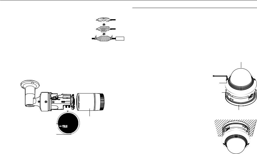
To adjust the zoom factor or focus (QNO-6072R)
A
System
1.Loosen the front cover as shown.
2.Loosen the zoom/focus lever slightly.
3.Position the zoom/focus lever to WIDE (NEAR) or TELE (FAR) as appropriate.
4.Then, tighten the zoom/focus lever to fix the adjusted position.
5.Turn the front cover to tighten it.
Front cover
Zoom Lever |
|
|
|
|
WIDE |
↔ |
TELE |
||
|
||||
Focus Lever |
FAR |
↔ |
NEAR |
|
|
||||
|
|
|||
JJ`` To ensure seamless waterproofing, tighten up the front cover by turning it to the end.
When combining the front cover, please combine the main body and the front cover so that the LOCK indicator is interlocked. `` Use the lever to adjust the zoom factor or focus, and turn the lever clockwise to fix it.
`` Before you can adjust the zoom factor/focus of the lens, loosen and remove the front cover.
INSTALLATION (QNV-6012R/6022R/6032R)
JJ`` This camera is waterproof and in compliance with the IP66 spec, but the jack connected to the external cable is not. You are recommended to install this product below the edge of eaves to prevent the cable from being externally exposed.
Precautions before installation
Ensure you read out the following instructions before installing the camera:
•• It must be installed on the area (ceiling or wall) that can withstand 5 times the weight of the camera including the installation bracket.
•• Stuck-in or peeled-off cables can cause damage to the product or a fire.
•• For safety purposes, keep anyone else away from the installation site. And put aside personal belongings from the site, just in case.
Disassembling
1.Using the L wrench provided, turn the 2 fastening bolts on the dome cover counter clockwise to remove the cover.
Dome cover
Bolts
Camera Body
Installation |
Camera Case |
|
1.Using the template provided as an accessory, drill the screw installation hole(diameter of 6mm, minimal depth of 55mm) and firmly insert the plastic anchor provided as an accessory to the end.
2. Fit the bottom hole to the anchor hole and insert and fix the taping screw (M4.5xL50).
3. Connect and arrange the necessary cables lest that they should be damaged or twisted while installing the camera.
4. Adjust the lens in a desired direction by referring to the “Adjusting the monitoring direction for the camera” section. (page 23)
5.Close the dome cover.
`` Securely fasten the fastening bolt using an L wrench to prevent water from leaking.
18_ installation & connection
Loading...