


 Loading...
Wisenet LNV-6072R, LNV-6032R, LNV-6022R, LNV-6012R, LNO-6032R User Manual
...NETWORK CAMERA
User Manual
LND-6012R/LND-6022R/LND-6032R/LND-6072R
LNO-6012R/LNO-6022R/LNO-6032R/LNO-6072R LNV-6012R/LNV-6022R/LNV-6032R/LNV-6072R

overview
IMPORTANT SAFETY INSTRUCTIONS
1.Read these instructions.
2.Keep these instructions.
3.Heed all warnings.
4.Follow all instructions.
5.Do not use this apparatus near water.
6.Clean the contaminated area on the product surface with a soft, dry cloth or a damp cloth.
(Do not use a detergent or cosmetic products that contain alcohol, solvents or surfactants or oil constituents as they may deform or cause damage to the product.)
7.Do not block any ventilation openings, Install in accordance with the manufacturer’s instructions.
8.Do not install near any heat sources such as radiators, heat registers, stoves, or other apparatus (including amplifiers) that produce heat.
9.Do not defeat the safety purpose of the polarized or grounding-type plug. A polarized plug has two blades with one wider than the other. A grounding type plug has two blades and a third grounding prong. The wide blade or the third prong are provided for your safety. If the provided plug does not fit into your outlet, consult an electrician for replacement of the obsolete outlet.
10.Protect the power cord from being walked on or pinched particularly at plugs, convenience receptacles, and the point where they exit from the apparatus.
11.Only use attachments/ accessories specified by the manufacturer.
12.Use only with the cart, stand, tripod, bracket, or table specified by the manufacturer, or sold with the apparatus. When a cart is used, use caution when moving the cart/ apparatus combination to avoid injury from tip-over.
13. Unplug this apparatus during lighting storms or when unused for long periods of time.
14. Refer all servicing to qualified service personnel. Servicing is required when the apparatus has been damaged in any way, such as power-supply cord or plug is damaged, liquid has
been spilled or objects have fallen into the apparatus, the apparatus has been exposed to rain or moisture, does not operate normally, or has been dropped.
15.This product is intended to be supplied by a Listed Power Supply Unit marked “Class 2” or “LPS” and rated from PoE , 0.14A.
16.This product is intended to be supplied by isolation power.
17.If you use excessive force when installing the product, the camera may be damaged and malfunction. If you forcibly install the product using non-compliant tools, the product may be damaged.
18.Do not install the product in a place where chemical substances or oil mist exists or may be generated. As edible oils such as soybean oil may damage or warp the product, do not install the product in the kitchen or near the kitchen table.
This may cause damage to the product.
19.When installing the product, be careful not to allow the surface of the product to be stained with chemical substance.
Some chemical solvents such as cleaner or adhesives may cause serious damage to the product’s surface.
20.If you install/disassemble the product in a manner that has not been recommended, the production functions/ performance may not be guaranteed.
Install the product by referring to “Installation & connection” in the user manual.
21.Installing or using the product in water can cause serious damage to the product.
WARNING
TO REDUCE THE RISK OF FIRE OR ELECTRIC SHOCK, DO NOT EXPOSE THIS PRODUCT TO RAIN OR MOISTURE. DO NOT INSERT ANY METALLIC OBJECT THROUGH THE VENTILATION GRILLS OR OTHER OPENNINGS ON THE EQUIPMENT.
Apparatus shall not be exposed to dripping or splashing and that no objects filled with liquids, such as vases, shall be placed on the apparatus.
To prevent injury, this apparatus must be securely attached to the Wall/ceiling in accordance with the installation instructions.
CAUTION
CAUTION
RISK OF ELECTRIC SHOCK.
DO NOT OPEN
CAUTION : TO REDUCE THE RISK OF ELECTRIC SHOCK.
DO NOT REMOVE COVER (OR BACK).
NO USER SERVICEABLE PARTS INSIDE.
REFER SERVICING TO QUALIFIED SERVICE PERSONNEL.
EXPLANATION OF GRAPHICAL SYMBOLS
The lightning flash with arrowhead symbol, within an equilateral triangle, is intended to alert the user to the presence of “dangerous voltage” within the product’s enclosure that may be of sufficient magnitude to constitute a risk of electric shock to persons.
The exclamation point within an equilateral triangle is intended to alert the user to the presence of important operating and maintenance (servicing) instructions in the literature accompanying the product.
OVERVIEW ●●
English _3

overview
Class  construction
An apparatus with CLASS construction shall be connected to a MAINS socket outlet with a protective earthing connection.
Battery
Batteries(battery pack or batteries installed) shall not be exposed to excessive heat such as sunshine, fire or the like.
The battery cannot be replaced.
Disconnection Device
Disconnect the main plug from the apparatus, if it’s defected. And please call a repair man in your location.
When used outside of the U.S., it may be used HAR code with fittings of an approved agency is employed.
CAUTION
RISK OF EXPLOSION IF BATTERY IS REPLACED BY AN INCORRECT TYPE. DISPOSE OF USED BATTERIES ACCORDING TO THE INSTRUCTIONS.
ATTENTION
IL Y A RISQUE D’EXPLOSION SI LA BATTERIE EST REMPLACÉE PAR UNE BATTERIE DE TYPE INCORRECT.
METTRE AU REBUT LES BATTERIES USAGÉES CONFORMÉMENT AUX INSTRUCTIONS.
These servicing instructions are for use by qualified service personnel only.
To reduce the risk of electric shock do not perform any servicing other than that contained in the operating instructions unless you are qualified to do so.
Please use the input power with just one camera and other devices must not be connected.
The ITE is to be connected only to PoE networks without routing to the outside plant. The wired LAN hub providing power over the Ethernet (PoE) in accordance with IEEE 802-3af shall be a UL Listed device with the output evaluated as a Limited Power Source as defined in UL60950-1.
Unit is intended for installation in a Network Environment 0 as defined in IEC TR 62102. As such, associated Ethernet wiring shall be limited to inside the building.
Please read the following recommended safety precautions carefully.
yyDo not place this apparatus on an uneven surface.
yyDo not install on a surface where it is exposed to direct sunlight, near heating equipment or heavy cold area.
yyDo not place this apparatus near conductive material. yyDo not attempt to service this apparatus yourself. yyDo not place a glass of water on the product.
yyDo not install near any magnetic sources. yyDo not block any ventilation openings. yyDo not place heavy items on the product.
yyPlease wear protective gloves when installing/removing the camera. The high temperature of the product surface may cause a burn.
User’s Manual is a guidance book for how to use the products. The meaning of the symbols are shown below.
yyReference : In case of providing information for helping of product’s usages
yyNotice : If there’s any possibility to occur any damages for the goods and human caused by not following the instruction
Please read this manual for the safety before using of goods and keep it in the safe place.
WARNING
To prevent damage which may caused by IR LED, don’t stare at operating lamp. For below models only.
LND-6012R/LND-6022R/LND-6032R/LND-6072R
LNO-6012R/LNO-6022R/LNO-6032R/LNO-6072R
LNV-6012R/LNV-6022R/LNV-6032R/LNV-6072R
Risk Group 1
WARNING IR emitted from this product.
Do not stare at operating lamp.
Product tested against IEC 62471
4_ overview

CONTENTS
OVERVIEW |
6 |
Product Features |
3 |
3 |
Important Safety Instructions |
6 |
Recommended PC Specifications |
|
6 |
Recommended Micro SD/SDHC Memory |
|
7 |
Card Specifications |
|
|
What’s Included (LND- |
|
|
7 |
6012R/6022R/6032R/6072R) |
|
What’s Included (LNO- |
|
|
8 |
6012R/6022R/6032R/6072R) |
|
What’s Included (LNV- |
|
|
9 |
6012R/6022R/6032R/6072R) |
|
At a Glance (LND-6012R/6022R/6032R) |
|
|
10 |
At a Glance (LND-6072R) |
|
12 |
At a Glance (LNO-6012R/6022R/6032R) |
|
12 |
At a Glance (LNO-6072R) |
|
13 |
At a Glance (LNV-6012R/6022R/6032R) |
|
14 |
At a Glance (LNV-6072R) |
INSTALLATION & CONNECTION |
15 |
6012R/6022R/6032R/6072R) |
15 |
Installation (LND- |
|
16 |
Installation (LNO- |
|
18 |
6012R/6022R/6032R/6072R) |
|
Installation (LNV- |
||
|
20 |
6012R/6022R/6032R/6072R) |
|
Inserting/Removing a Micro SD Memory |
|
|
22 |
Card |
|
Powering and networking |
NETWORK CONNECTION AND SETUP
23
23 Connecting the Camera Directly to Local Area Networking
23 Connecting the Camera Directly to a DHCP Based DSL/Cable Modem
24 Using Device Manager
24 Automatically searching camera
24 Configuring IP address
25 Manually registering camera
25 Automatically configuring IP
26 Port Range Forward (Port Mapping) Setup
27 Connecting to the Camera from a Shared Local PC
27 Connecting to the Camera from a Remote PC via the Internet
WEB VIEWER |
29 |
Password setting |
28 |
28 |
Connecting to the Camera |
29 |
Login |
|
29 |
Camera Web Viewer Setup |
|
APPENDIX |
30 |
LNO-6012R/6022R/6032R, LNV- |
30 |
Specification (LND-6012R/6022R/6032R, |
|
32 |
6012R/6022R/6032R) |
|
Specification (LND-6072R, LNO-6072R, |
||
34 |
LNV-6072R) |
|
|
Product Overview |
|
|
37 |
Troubleshooting |
|
38 |
Open Source Announcement |
OVERVIEW ●●
English _5

overview
PRODUCT FEATURES
•• Dustproof/Waterproof (IP66) (LNO-6012R/6022R/6032R/6072R, LNV-6012R/6022R/6032R/6072R)
The dustproof and waterproof design makes you feel at ease when installing the product outdoors or exposing it to rain.
•• IR mode
If the IR indicator turns on, the product switches to the IR mode for preventing an object from being too bright, which helps you identify the object in near distance.
•• Supports 2 megapixel resolution videos
•• Multi-Streaming
This network camera can display videos in different resolutions and qualities simultaneously using different CODECs.
•• Web Browser-based Monitoring
Using the Internet web browser to display the image in a local network environment.
•• Alarm
When an event occurs, related videos are sent to the user’s registered e-mail and FTP server or stored on the Micro SD memory card.
•• Tampering Detection
Detects tempering attempts on video monitoring.
•• Motion Detection
Detects motion from the camera’s video input.
•• ONVIF Compliance
This product supports ONVIF Profile S/G/T. For more information, refer to www.onvif.org.
RECOMMENDED PC SPECIFICATIONS
•• CPU : Intel(R) Core(TM) i7 3.4 GHz or higher
•• RAM : 8G or higher
•• Supported OS: Windows 7, 8.1, 10, Mac OS X 10.12, 10.13, 10.14
•• Recommended Browser: Google Chrome
•• Supported Browser: MS Explore11, MS Edge, Mozilla Firefox(Window 64bit only), Apple Safari(Mac OS X only)
•• VGA : PCIe 256MB GDDR3 video graphics card or higher
Please see the appendix for detailed information on verified OS and browsers.
RECOMMENDED MICRO SD/SDHC MEMORY CARD SPECIFICATIONS
•• Recommended capacity : 16GB ~ 32GB (MLC Type)
•• Recommended Manufacturers : SanDisk, Transcend
•• Product Type : High endurance
•• The compatibility varies depending on the card manufacturers and types.
6_ overview
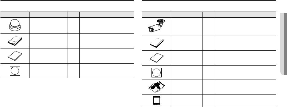
WHAT’S INCLUDED (LND-6012R/6022R/6032R/6072R)
Please check if your camera and accessories are all included in the product package. |
|||
(As for each sales country, accessories are not the same.) |
|
|
|
Appearance |
Item Name |
Quantity |
Description |
|
Camera |
1 |
|
|
Quick Guide |
1 |
|
|
Warranty card |
1 |
|
|
Template |
1 |
Product installation guide |
WHAT’S INCLUDED (LNO-6012R/6022R/6032R/6072R)
Please check if your camera and accessories are all included in the product package. |
|||
(As for each sales country, accessories are not the same.) |
|
||
Appearance |
Item Name |
Quantity |
Description |
|
Camera |
1 |
|
|
Quick Guide |
1 |
|
|
Warranty card |
1 |
|
|
Template |
1 |
Product installation guide |
|
RJ45 waterproof accessory |
1 |
Used to install in humid places |
|
Card-type moisture absorbent |
1 |
Attached when installed. |
OVERVIEW ●●
English _7
overview
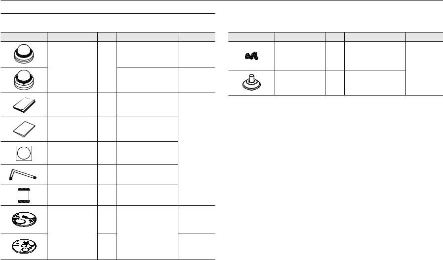
WHAT’S INCLUDED (LNV-6012R/6022R/6032R/6072R)
Please check if your camera and accessories are all included in the product package. (As for each sales country, accessories are not the same.)
Appearance |
Item Name |
Quantity |
Description |
Model Name |
|
|
|
|
LNV-6012R/6022R/ |
|
|
|
|
6032R |
|
Camera |
1 |
|
|
|
|
|
|
LNV-6072R |
|
Quick Guide |
1 |
|
|
|
Warranty card |
1 |
|
|
|
Template |
1 |
Product installation guide |
Use for all models |
|
|
|||
|
Star-shaped wrench |
1 |
Used for the assembly and disassembly |
|
|
of dome covers |
|
||
|
|
|
|
|
|
Card-type moisture absorbent |
1 |
Attached when installed. |
|
|
|
1 |
|
LNV-6012R/ |
|
|
|
6022R/6032R |
|
|
|
|
This is used to place the camera on a |
|
|
Mount plate |
|
|
|
|
|
mount separately sold. |
|
|
|
|
|
|
|
|
|
1 |
|
LNV-6072R |
Appearance |
Item Name |
Quantity |
Description |
Model Name |
|
|
|
Used for assembling the dome case |
|
|
Machine Screws |
2 |
when installing the product on the |
|
|
pipe, wall mount, etc. or blocking a |
|
||
|
|
|
hole. |
Use for all models |
|
|
|
|
|
|
Cable bush |
1 |
Used to connect the LAN cable with a |
|
|
diameter of Ø7~8.5. |
|
||
|
|
|
|
8_ overview
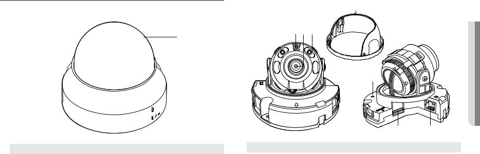
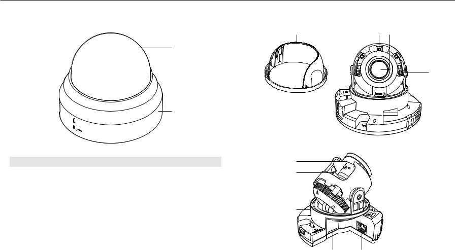
AT A GLANCE (LND-6012R/6022R/6032R)
Appearance
a

 b
b
Item |
Description |
a Dome cover |
Case cover used to protect the lens and the main unit. |
|
|
b Camera Case |
Housing part that covers the camera body. |
Components
a
bcd
e
ACTLINK
NETWORK
RESET
FRONT
ACTNETWORK
LINK
f g
Item |
Description |
|
a Inside cover |
Protective cover for the main body. |
|
|
|
|
b Illumination Sensor |
Detects incoming light to control the IR LED. |
|
|
|
|
c Lens |
Lens for the camera. |
|
|
|
|
d IR LED |
These infrared LED’s are controlled by the illumination sensor. |
|
|
|
|
|
The button restores all camera settings to the factory default. |
|
|
Press and hold for about 5 seconds to reboot the system. |
|
e Reset Button |
J If you reset the camera, the network settings will be adjusted so that DHCP can be |
|
enabled. If there is no DHCP server in the network, you must run the Device Manager |
||
|
program to change the basic network settings such as IP address, Subnet mask, |
|
|
Gateway, etc., before you can connect to the network. |
|
Micro SD Memory Card |
Compartment for the Micro SD memory card. |
|
f Compartment |
||
g PoE connector |
Supply power through the Ethernet cable and connect to the network. |
|
|
|
|
OVERVIEW ●●
English _9
overview
AT A GLANCE (LND-6072R) |
Components |
Appearance |
|
a |
b c |
a
d
ETWORKN
b
Item |
Description |
i |
a Dome cover |
Case cover used to protect the lens and the main unit. |
h |
|
|
|
b Camera Case |
Housing part that covers the camera body. |
|
g
RESET
F

ACT LINK
NETWORK
f e
10_ overview
Item |
|
|
Description |
|
a Inside cover |
Protective cover for the main body. |
|||
|
|
|||
b Illumination Sensor |
Detects incoming light to control the IR LED. |
|||
|
|
|||
c Lens |
Lens for the camera. |
|||
|
|
|
||
d IR LED |
These infrared LED’s are controlled by the illumination sensor. |
|||
|
|
|
||
e PoE connector |
Supply power through the Ethernet cable and connect to the network. |
|||
|
|
|
|
|
Micro SD Memory Card |
Compartment for the Micro SD memory card. |
|||
f Compartment |
||||
|
The button restores all camera settings to the factory default. |
|||
|
Press and hold for about 5 seconds to reboot the system. |
|||
g Reset Button |
J If you reset the camera, the network settings will be adjusted so that DHCP can be |
|||
|
enabled. If there is no DHCP server in the network, you must run the Device Manager |
|||
|
|
program to change the basic network settings such as IP address, Subnet mask, |
||
|
|
Gateway, etc., before you can connect to the network. |
||
|
T |
|
Zoom in (Tele) |
|
h Zoom control lever |
W |
|
Zoom out (Wide) |
|
Release the lever and move it to left or right to zoom the lens in or out. |
||||
|
||||
|
Turn the lever clockwise to fix the adjusted position to prevent it from being moved. |
|||
|
N |
|
Focusing on a near object (Near) |
|
i Focus control lever |
F |
|
Focusing on a far object (Far) |
|
Release the lever and move it to left or right to adjust the lens focus. |
||||
|
||||
|
Turn the lever clockwise to fix the adjusted position to prevent it from being moved. |
|||
OVERVIEW ●●
English _11
overview
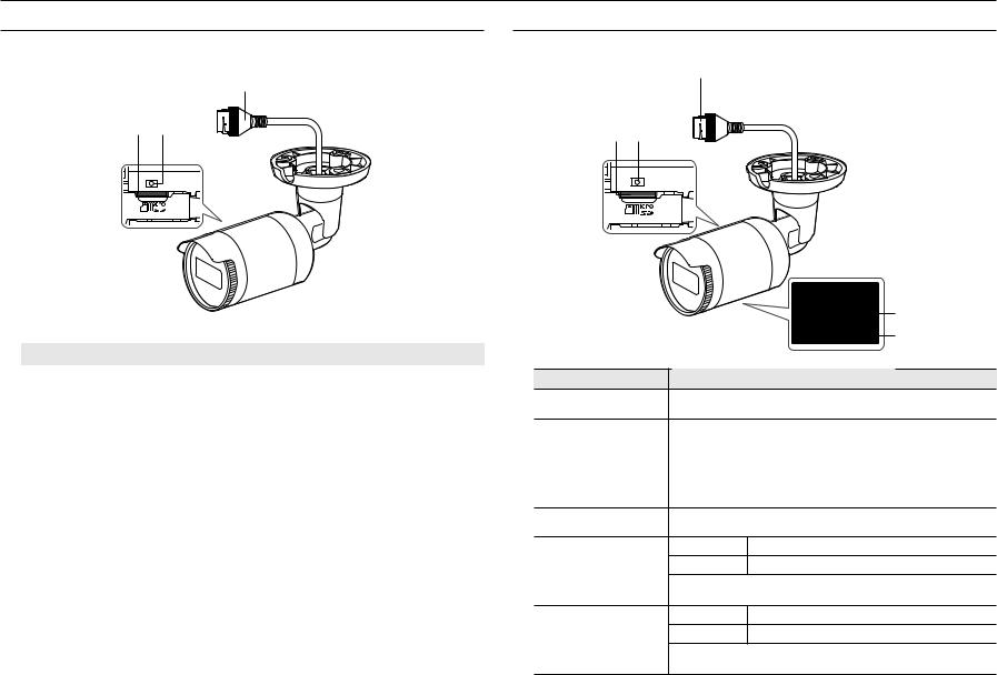
AT A GLANCE (LNO-6012R/6022R/6032R)
Appearance
c
a b |
AT A GLANCE (LNO-6072R)
Appearance
c
a b |
|
|
|
|
|
|
|
|
|
|
|
|
Item |
|
|
Description |
||
a Micro SD card slot |
(Internal space of the product) This is a slot in which you can insert a Micro SD card. |
||||
|
|
|
|
|
|
|
|
|
The button restores all camera settings to the factory default. |
||
|
|
|
Press and hold for about 5 seconds to reboot the system. |
||
b Reset button |
J If you reset the camera, the network settings will be adjusted so that DHCP can be |
||||
|
enabled. If there is no DHCP server in the network, you must run the Device Manager |
||||
|
|
|
|
program to change the basic network settings such as IP address, Subnet mask, |
|
|
|
|
|
Gateway, etc., before you can connect to the network. |
|
c PoE connector |
Supply power through the Ethernet cable and connect to the network. |
||||
|
|
d |
|
|
e |
Item |
|
Description |
a Micro SD card slot |
(Internal space of the product) This is a slot in which you can insert a Micro SD card. |
|
|
The button restores all camera settings to the factory default. |
|
|
Press and hold for about 5 seconds to reboot the system. |
|
b Reset button |
J If you reset the camera, the network settings will be adjusted so that DHCP can be |
|
|
enabled. If there is no DHCP server in the network, you must run the Device Manager |
|
|
|
program to change the basic network settings such as IP address, Subnet mask, |
|
|
Gateway, etc., before you can connect to the network. |
c PoE connector |
Supply power through the Ethernet cable and connect to the network. |
|
|
N |
Focusing on a near object (Near) |
d Focus control lever |
F |
Focusing on a far object (Far) |
|
Release the lever and move it to left or right to adjust the lens focus. |
|
|
Turn the lever clockwise to fix the adjusted position to prevent it from being moved. |
|
|
T |
Zoom in (Tele) |
e Zoom control lever |
W |
Zoom out (Wide) |
|
Release the lever and move it to left or right to zoom the lens in or out. |
|
|
Turn the lever clockwise to fix the adjusted position to prevent it from being moved. |
|
12_ overview
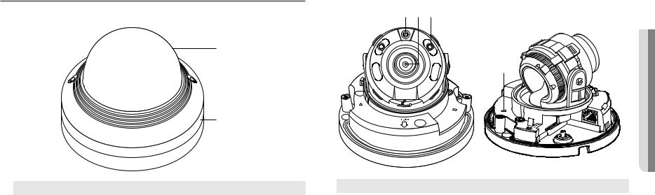
AT A GLANCE (LNV-6012R/6022R/6032R)
Appearance
a
b
Item |
Description |
a Dome cover |
Case cover used to protect the lens and the main unit. |
b Camera Case |
Housing part that covers the camera body. |
Components
abc
|
|
●● |
|
d |
OVERVIEW |
|
|
|
TRESE |
|
NETWORK |
|
LINK |
|
|
RESET |
|
|
|
|
|
|
|
|
|
|
|
|
|
|
|
|
|
|
|
|
|
e |
f |
||
|
|
|
|
|
|
Item |
Description |
|
|
||
a Illumination Sensor |
Detects incoming light to control the IR LED. |
|
|
||
|
|
|
|
|
|
b Lens |
Lens for the camera. |
|
|
||
|
|
|
|
|
|
c IR LED |
These infrared LED’s are controlled by the illumination sensor. |
|
|
||
|
|
|
|
|
|
|
The button restores all camera settings to the factory default. |
|
|
||
|
Press and hold for about 5 seconds to reboot the system. |
|
|
||
d Reset button |
J If you reset the camera, the network settings will be adjusted so that DHCP can be |
||||
enabled. If there is no DHCP server in the network, you must run the Device Manager |
|||||
|
program to change the basic network settings such as IP address, Subnet mask, |
||||
|
Gateway, etc., before you can connect to the network. |
|
|
||
Micro SD Memory Card |
Compartment for the Micro SD memory card. |
|
|
||
e Compartment |
|
|
|||
f PoE connector |
Supply power through the Ethernet cable and connect to the network. |
|
|
||
|
|
|
|
|
|
English _13

overview
AT A GLANCE (LNV-6072R) |
|
Components |
Appearance |
|
a b c |
|
|
|
|
|
d |
|
a |
e |
|
|
b
Item |
Description |
a Dome cover |
Case cover used to protect the lens and the main unit. |
|
|
b Camera Case |
Housing part that covers the camera body. |
14_ overview
NK |
|
LiNK |
ACT |
|
|
Item
a Illumination Sensor
b Lens
c IR LED
d Focus control lever
e Zoom control lever
f Reset button
g Micro SD Memory Card
Compartment
h PoE connector
f
RESET |
|
g |
h |
Description |
|
Detects incoming light to control the IR LED.
Lens for the camera.
These infrared LED’s are controlled by the illumination sensor.
N |
Focusing on a near object (Near) |
F |
Focusing on a far object (Far) |
Release the lever and |
move it to left or right to adjust the lens focus. |
Turn the lever clockwise to fix the adjusted position to prevent it from being moved. |
|
T |
Zoom in (Tele) |
W |
Zoom out (Wide) |
Release the lever and move it to left or right to zoom the lens in or out.
Turn the lever clockwise to fix the adjusted position to prevent it from being moved.
The button restores all camera settings to the factory default. Press and hold for about 5 seconds to reboot the system.
J If you reset the camera, the network settings will be adjusted so that DHCP can be enabled. If there is no DHCP server in the network, you must run the Device Manager program to change the basic network settings such as IP address, Subnet mask, Gateway, etc., before you can connect to the network.
Compartment for the Micro SD memory card.
Supply power through the Ethernet cable and connect to the network.
installation & connection
INSTALLATION (LND-6012R/6022R/6032R/6072R)
Precautions before installation
Ensure you read out the following instructions before installing the camera:
•• It must be installed on the area (ceiling or wall) that can withstand 5 times the weight of the camera including the installation bracket.
•• Stuck-in or peeled-off cables can cause damage to the product or a fire.
•• For safety purposes, keep anyone else away from the installation site. And put aside personal belongings from the site, just in case.
•• For the manual variable focal lens camera, features such as focus and zoom should be adjusted before installation.
When adjusting these, be sure to prevent foreign substances from becoming attached.
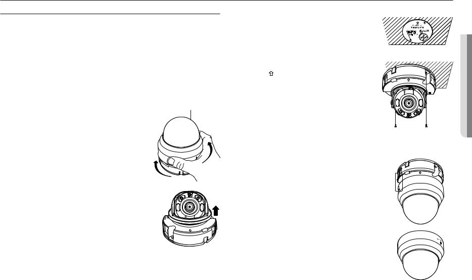
Disassembling
1. Use one hand to hold the camera’s bottom part and turn the cover |
Dome Cover |
counterclockwise with another hand to separate it. |
|
JJ`` Do not touch the transparent part of the dome cover once the protective film is |
|
removed. |
|
2. Lift up the inner cover to separate it.
LINK
FRONT
Installation
1.Consider the direction to be monitored, attach the template, and drill holes by following the template.
2.Using 2 tapping screws, fix the camera at 2 holes drilled with a template.
`` Set the < > mark imprinted on the camera to face the direction of camera monitoring.
3.Connect the camera internal terminal with the corresponding cable.
4.Adjust the lens in a desired direction by referring to the “Adjusting the monitoring direction for the camera” section. (page 20)
FRONT
NETWORK ACT LINK
JJ`` |
You are recommended not to touch the lens separately, as it is shipped |
|
|
from the factory with the focus correctly adjusted when the inspection is |
|
|
completed. Touching the lens may cause the focus to become distorted or |
|
`` |
the lens to become dirty. (LND-6012R/6022R/6032R) |
|
For the manual variable focal lens camera, features such as focus and zoom should be adjusted before installation. |
||
|
When adjusting these, be sure to prevent foreign substances from becoming attached. (LND-6072R) |
|
5. Please connect the inner cover to the main body. |
|
|
6. While grabbing the bottom side of the camera with your hand, please |
|
|
grab and push its cover with the other hand to align the two arrow signs, |
FRONT |
|
as shown in the figure. |
|
|
JJ`` |
To assemble the dome cover, make the arrows match each other and press the |
|
|
cover firmly. |
|
|
If the dome cover is rotated during assembly or is assembled incorrectly, diffused |
|
|
reflection may occur or the lens section may rotate, which will cause the shooting |
|
`` |
range to be changed. |
|
Make sure that the dome cover is correctly connected to the bottom part as shown |
|
|
|
in the figure. |
|
If the snap-fit is not connected correctly, the dome cover may fall, which may cause injury.
CONNECTION & INSTALLATION ●●
English _15
Loading...