

Wisenet SDH-B84045BF, SDR-84305, SDC-89445BF, SDH-C84085BF, SDH-C85105BF Quick Start Manual
...
5M VIDEO SECURITY SYSTEM
Quick Start Guide
2_ English
If you are experiencing video loss, verify that all cables are properly and securely connected to the DVR.
•Check your Network Connection
•Check your Username and Password
•Restart the DVR if you have trouble connecting.
Main Menu > Shutdown > Enter Username & Password > Click “Reboot”
To reset your DVR to factory settings, refer to the User manual.
For more information about your product, please download the User Manual from "wisenetlife.com".
Troubleshooting
Need Help?
Contact our Technical Supprt Team
844-WISENET
(844-947-3638)
Open 7 days a week
English _3
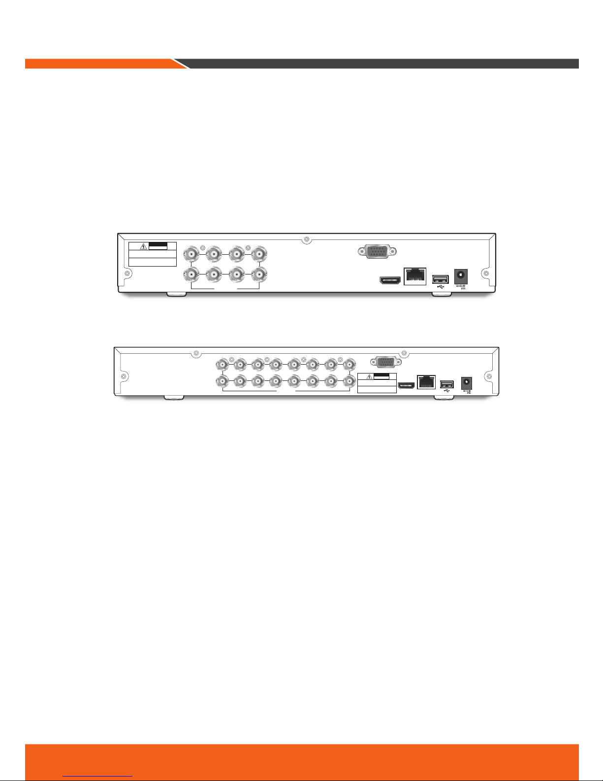
DVR Setup
KIT Model
SDH-B84045BF/SDH-C84085BF/SDH-C85105BF
DVR Model
SDR-84305/SDR-85305
•8CH DVR
•16CH DVR
HDMI
VGA
LAN
7 5 3 1
8 6 4 2
VIDEO INPUT
12V
CAUTION
RISK OF ELECTRI SHOCK
DO NOT OPEN
CAUTION : TO REDUCE THE RISK OF ELECTRICAL SHOCK
DO NOT OPEN COVERS. NO USER SERVICEABLE
PARTS INSIDE. REFER SERVICING TO QUALIFIED
SERVICE PERSONNEL.
WARNING : TO PREVENT FIRE OR SHOCK HAZARD. DO NOT
EXPOSE UNITS NOT SPECIFICALLY DESIGNED
FOR OUTDOOR USE TO RAIN OR MOISTURE.
HDMI
VGA
LAN
VIDEO INPUT
123
4
5
6
7
8
9
10
11
12
13
14
15
16
12V
CAUTION
RISK OF ELECTRI SHOCK
DO NOT OPEN
CAUTION : TO REDUCE THE RISK OF ELECTRICAL SHOCK
DO NOT OPEN COVERS. NO USER SERVICEABLE
PARTS INSIDE. REFER SERVICING TO QUALIFIED
SERVICE PERSONNEL.
WARNING : TO PREVENT FIRE OR SHOCK HAZARD. DO NOT
EXPOSE UNITS NOT SPECIFICALLY DESIGNED
FOR OUTDOOR USE TO RAIN OR MOISTURE.

4_ English
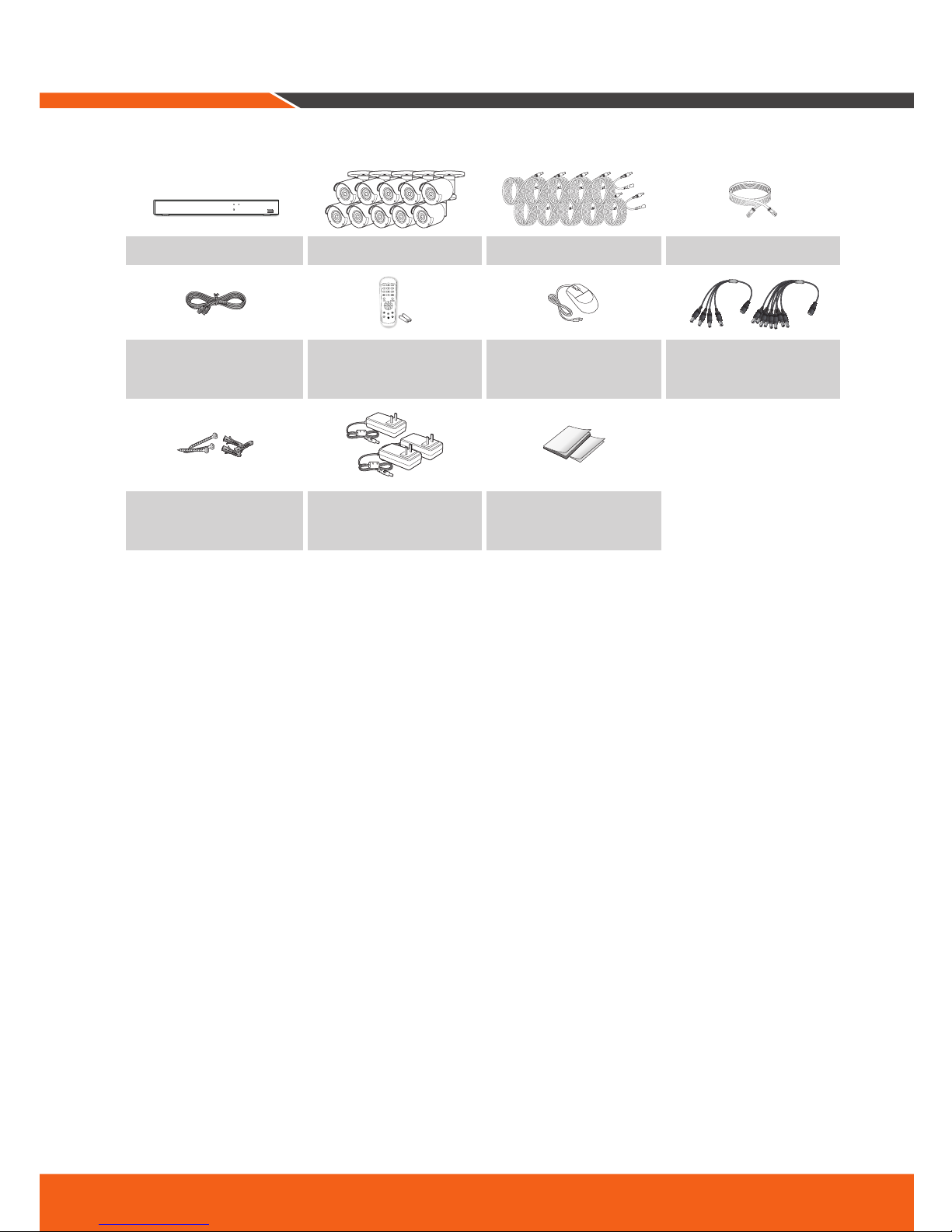
Package Contents
The appearance of the components may differ from the image shown.
Accessory category and quantity may differ depending on sales region.
The administrator is recommended to store the remote control carefully in order to initialize it if the password is
lost.
•SDH-B84045BF
USB
REC NET PWR
SDR-84305 SDC-89445BF 60ft camera cable Ethernet cable
HDMI Cable
Remote Control /
Remote Control Battery
(AAA x 2)
Mouse Power splitter
Screw x 3EA (per Camera) /
Anchor x 3EA (per Camera)
Power adaptor for DVR /
Power adaptor for 4 Cameras
Printed Material
•SDH-C84085BF
USB
REC NET PWR
SDR-84305 SDC-89445BF 60ft camera cable Ethernet cable
HDMI Cable
Remote Control /
Remote Control Battery
(AAA x 2)
Mouse Power splitter (2PCS)
Screw x 3EA (per Camera) /
Anchor x 3EA (per Camera)
Power adaptor for DVR /
Power adaptor for 4
Cameras(2PCS)
Printed Material
DVR Setup
English _5
•SDH-C85105BF
PWR HDD
USB
SDR-85305 SDC-89445BF 60ft camera cable Ethernet cable
HDMI Cable
Remote Control /
Remote Control Battery
(AAA x 2)
Mouse Power splitter (2PCS)
Screw x 3EA (per Camera) /
Anchor x 3EA (per Camera)
Power adaptor for DVR,
Power adaptor for 6 cameras,
Power adaptor for 4 cameras
Printed Material

6_ English
1.
Connect the camera's video input (yellow) and power supply (red) connectors to the BNC extension cables.
Then connect the BNC video input (yellow) to the video input port on the rear panel. (Repeat Step 1 for the
remaining cameras.)
2.
Connect the mouse to the USB Port on the front or back panel of the DVR.
3.
Depending on the monitor port, connect the HDMI or VGA cable from your monitor to the HDMI or VGA
Port on the rear panel.
HDMI
DVR Setup
HDMI
VGA
LAN
7 5 3 1
8 6 4 2
VIDEO INPUT
12V
CAUTION
RISK OF ELECTRI SHOCK
DO NOT OPEN
CAUTION : TO REDUCE THE RISK OF ELECTRICAL SHOCK
DO NOT OPEN COVERS. NO USER SERVICEABLE
PARTS INSIDE. REFER SERVICING TO QUALIFIED
SERVICE PERSONNEL.
WARNING : TO PREVENT FIRE OR SHOCK HAZARD. DO NOT
EXPOSE UNITS NOT SPECIFICALLY DESIGNED
FOR OUTDOOR USE TO RAIN OR MOISTURE.
For
Cameras
For
DVR
5 1
43
2
6
HDMI
VGA
LAN
7 5 3 1
8 6 4 2
VIDEO INPUT
12V
CAUTION
RISK OF ELECTRI SHOCK
DO NOT OPEN
CAUTION : TO REDUCE THE RISK OF ELECTRICAL SHOCK
DO NOT OPEN COVERS. NO USER SERVICEABLE
PARTS INSIDE. REFER SERVICING TO QUALIFIED
SERVICE PERSONNEL.
WARNING : TO PREVENT FIRE OR SHOCK HAZARD. DO NOT
EXPOSE UNITS NOT SPECIFICALLY DESIGNED
FOR OUTDOOR USE TO RAIN OR MOISTURE.
TO DVR
TO CAMERA
2 1

English _7
4.
Connect one end of the Ethernet cable into your router’s LAN port, and the other end of the cable to the
Ethernet port on the rear panel.
5.
Connect the camera's power supply (red) to the power splitter. Then connect the other end of the power
splitter to the power adapter for Cameras and plug in the adapter to a wall outlet. (Repeat Step 5 to connect the cameras to the second set of power splitter and power adapter.)
6.
Connect the power adapter for DVR to the DC 12V port on the rear panel and the power plug into a wall
outlet. The DVR will automatically power on and the startup wizard will appear on your monitor.
HDMI
VGA
LAN
7 5 3 1
8 6 4 2
VIDEO INPUT
12V
CAUTION
RISK OF ELECTRI SHOCK
DO NOT OPEN
CAUTION : TO REDUCE THE RISK OF ELECTRICAL SHOCK
DO NOT OPEN COVERS. NO USER SERVICEABLE
PARTS INSIDE. REFER SERVICING TO QUALIFIED
SERVICE PERSONNEL.
WARNING : TO PREVENT FIRE OR SHOCK HAZARD. DO NOT
EXPOSE UNITS NOT SPECIFICALLY DESIGNED
FOR OUTDOOR USE TO RAIN OR MOISTURE.
For
DVR
LAN
HDMI
VGA
LAN
7 5 3 1
8 6 4 2
VIDEO INPUT
12V
CAUTION
RISK OF ELECTRI SHOCK
DO NOT OPEN
CAUTION : TO REDUCE THE RISK OF ELECTRICAL SHOCK
DO NOT OPEN COVERS. NO USER SERVICEABLE
PARTS INSIDE. REFER SERVICING TO QUALIFIED
SERVICE PERSONNEL.
WARNING : TO PREVENT FIRE OR SHOCK HAZARD. DO NOT
EXPOSE UNITS NOT SPECIFICALLY DESIGNED
FOR OUTDOOR USE TO RAIN OR MOISTURE.
TO DVR
TO CAMERA
For
Cameras
3
2
1
 Loading...