

Page 1
Operating Instructions — Parts Manual
15-Inch Vari-Speed Drill Press
Models: A5816, A5818, A3816, A3818
Manufactured after Serial No. 807137 Part No.
5507564
Revision B6
WMH Tool Group, Inc.
2420 Vantage Dr.
Elgin, IL 60123
Ph: 847-649-3010
Fax:
847-851-1144
Page 2

Page 3

Table of Contents
Cover Page.......................................................................................................................... 1
General Specifications....................................................................................................... 4
Operating Precautions....................................................................................................... 5
Set-up and Operation......................................................................................................... 7
Maintenance........................................................................................................................ 9
Wiring Diagrams............................................................................................................... 10
Troubleshooting ................................................................................................................11
Replacement Parts ........................................................................................................... 12
3
Page 4
General Specifications
The Wilton 15-Inch Vari-Speed Drill Presses, Models
A5816, A5818, A5836, and A5838 provide drilling
speeds from 400 to 5,000 rpm. Simple handwheel
adjustment sets the speeds with an LED speed
display on the faceplate of the machine.
Wilton's 15-inch vari-speed drill press provides a solid
base for drilling and offers a wide range of spindle
speeds. The large quill provides greater accuracy.
The large worktable provides the operator with room
to work and ample support for the workpiece. The
drill press has a 3-inch diameter column for head and
table support. The 15-Inch Vari-Speed Drill Press is
equipped with a standard table raiser.
Specifications
Model............................ A5816 ..................... A5818....................... A5836 .......................A5838
A3816 A3818 A3836 A3838
Type .............................. Floor Model............. Floor Model .............. Bench Model ............. Bench Model
4
Motor:
Motor Speed (rpm) .... 1,725 rpm................ 1,725 rpm ................. 1,725 rpm..................1,725 rpm
HP ............................. 1 HP ........................ 3 HP ......................... 1 HP ..........................3 HP
Power Rating............. 1 Ph, 115/220V........ 3 Ph, 220/440V......... 1 Ph, 115/220V .........3 Ph, 220/440V
Spindle speed (rpm) ...... 400 to 5,000rpm...... 400 to 5,000 rpm ...... 400 to 5,000 rpm....... 400 to 5,000rpm
Capacity:
Cast iron.................... up to 5/8-in. ............. up to 5/8-in. .............. up to 5/8-in. .............. up to 5/8-in.
Steel .......................... up to 1/2-in. ............. up to 1/2-in. .............. up to 1/2-in...............up to 1/2-in.
Drills to center ............... 15 in. ....................... 15 in. ........................ 15 in. .........................15 in.
Quill diameter ................ 2-1/4 in. ................... 2-1/4 in. .................... 2-1/4 in......................2-1/4 in.
Quill travel ..................... 6 in. ......................... 6 in. .......................... 6 in. ...........................6 in.
Spindle taper ................. #2 MorseTaper ........ #2 MorseTaper ......... #2 MorseTaper .......... #2 MorseTaper
Dimensions:
Table (overall)............ 15-1/4 x 17-3/4 in. ... 15-1/4 x 17-3/4 in. .... 15-1/4 x 17-3/4 in. .....15-1/4 x 17-3/4 in.
Table (working area).. 12-1/2 x 14-1/2 in. ... 12-1/2 x 14-1/2 in. .... 12-1/2 x 14-1/2 in. .....12-1/2 x 14-1/2 in.
T-slot ......................... 1/2-in....................... 1/2-in. ....................... 1/2-in.........................1/2-in.
Spindle to table.......... 41 in. ....................... 41 in. ........................ 41 in. .........................41 in.
Spindle to base .......... 47-1/2 in. ................. 47-1/2 in. .................. 47-1/2 in. ...................47-1/2 in.
Overall height ............ 67-1/2 in. .................67-1/2 in.
Page 5

- Misuse of this machine can cause serious injury.
- For safety, machine must be set up, used and
serviced properly.
- Read, understand and follow instructions in the
Operating Instructions and Parts Manual which
was shipped with your machine.
supply while servicing.
- Always follow instructions in Operating Instructions and Parts Manual when changing accessory
tools or parts.
- Never modify the machine without consulting
Wilton Corporation.
You—the stationary power tool user—
When setting up machine:
- Always avoid using machine in damp or poorly
lighted work areas.
- Always be sure the machine support is securely
anchored to the floor or the work bench.
When using machine:
- Always wear safety glasses with side shields
(See ANSI Z87.1)
- Never wear loose clothing or jewelry.
- Never overreach—you may slip and fall.
When servicing machine:
- Always disconnect the machine from its electrical
hold the key to safety.
Read and follow these simple rules for best results
and full benefits from your machine. Used properly,
Wilton’s machinery is among the best in design and
safety. However, any machine used improperly can
be rendered inefficient and unsafe. It is absolutely
mandatory that those who use our products be
properly trained in how to use them correctly. They
should read and understand the Operating Instructions and Parts Manual as well as all labels affixed
to the machine. Failure in following all of these
warnings can cause serious injuries.
Machinery general safety warnings
1. Always wear protective eye wear when operat-
ing machinery. Eye wear shall be impact resistant, protective safety glasses with side shields
which comply with ANSI Z87.1 specifications.
Use of eye wear which does not comply with
ANSI Z87.1 specifications could result in severe
injury from breakage of eye protection.
2. Wear proper apparel. No loose clothing or
jewelry which can get caught in moving parts.
Rubber soled footwear is recommended for best
footing.
3. Do not overreach. Failure to maintain proper
working position can cause you to fall into the
machine or cause your clothing to get caught —
pulling you into the machine.
4. Keep guards in place and in proper working
order. Do not operate the machine with guards
removed.
5. Avoid dangerous working environments. Do not
use stationary machine tools in wet or damp
locations. Keep work areas clean and well lit.
6. Avoid accidental starts by being sure the start
switch is “OFF” before plugging in the machine.
7. Never leave the machine running while unat-
tended. Machine shall be shut off whenever it is
not in operation.
8. Disconnect electrical power before servicing.
Whenever changing accessories or general
maintenance is done on the machine, electrical
power to the machine must be disconnected
before work is done.
9. Maintain all machine tools with care. Follow all
maintenance instructions for lubricating and the
changing of accessories. No attempt shall be
made to modify or have makeshift repairs done to
the machine. This not only voids the warranty but
also renders the machine unsafe.
10. Machinery must be anchored to the floor.
11 . Secure work. Use clamps or a vise to hold work,
when practical. It is safer than using your hands
and it frees both hands to operate the machine.
12. Never brush away chips with machine in operation.
13. Keep work area clean. Cluttered areas invite
accidents.
14. Remove adjusting keys and wrenches before
turning machine on.
15. Use the right tool. Don’t force a tool or attachment
to do a job it was not designed for.
16. Use only recommended accessories and follow
manufacturers instructions pertaining to them.
17. Keep hands in sight and clear of all moving parts
and cutting surfaces.
18. All visitors should be kept at a safe distance from
the work area. Make workshop completely safe
by using padlocks, master switches, or by
removing starter keys.
19. Know the tool you are using — its application,
limitations, and potential hazards.
5
Page 6

General electrical cautions
The drill press should be grounded in accordance
with the National Electrical Code and local codes
and ordinances. This work should be done by a
qualified electrician. The drill press should be
grounded to protect the user from electrical shock.
Wire sizes
Caution: for circuits which are far away from the
electrical service box, the wire size must be
increased in order to deliver ample voltage to the
motor. To minimize power losses and to prevent
motor overheating and burnout, the use of wire sizes
for branch circuits or electrical extension cords
according to the following table is recommended.
AWG (American wire gauge) number
Conductor length 240 volt lines 120 volt lines
0-50 feet No. 14 No. 14
50-100 feet No. 14 No. 12
Over 100 feet No. 12 No. 8
Safety Instructions for Drill
Presses
1. All work shall be secured using either clamps or a
vise to the drill press table. It is unsafe to use your
hands to hold any workpiece being drilled.
2. Drill press head and table shall be securely
locked to the column before operating the drill press.
This must always be checked prior to starting the
machine.
3. Always use the correct tooling. Tooling shall
always be maintained and properly sharpened. All
tooling must be run at the proper speeds and feeds
as they apply to the job. Use only recommended
accessories and follow those manufacturers instructions pertaining to them. Tooling shall be not be
forced in to any workpiece but fed according to the
6
proper specifications. Failure to follow these instructions will not only ruin the tooling as well as the
machine, but can cause serious injury.
4. Never brush away any chips while the machine is
in operation. All clean up should be done when the
machine is stopped.
5. Keep hands in sight. Do not put hands or fingers
around, on, or below any rotating cutting tools.
Leather safety gloves should be used when handling
any sharp objects or cutting tools. See Figure A.
6. Always wear protective eye wear when operating,
servicing or adjusting machinery. Eyewear shall be
impact resistant, protective safety glasses with side
shields complying with ANSI Z87.1 specifications.
Use of the eye wear which does not comply with
ANSI Z87.1 specifications could result in severe
injury from breakage of eye protection. See Figure
B.
7. When drilling in material which causes dust, a
dust mask shall be worn. See Figure C.
8. Avoid contact with coolant, especially guarding
the eyes.
9. Non-slip footwear and safety shoes are recommended. See Figure D.
10. Wear ear protectors (plugs or muffs) during
extended periods of operation. See Figure E.
A B C
D E
Page 7

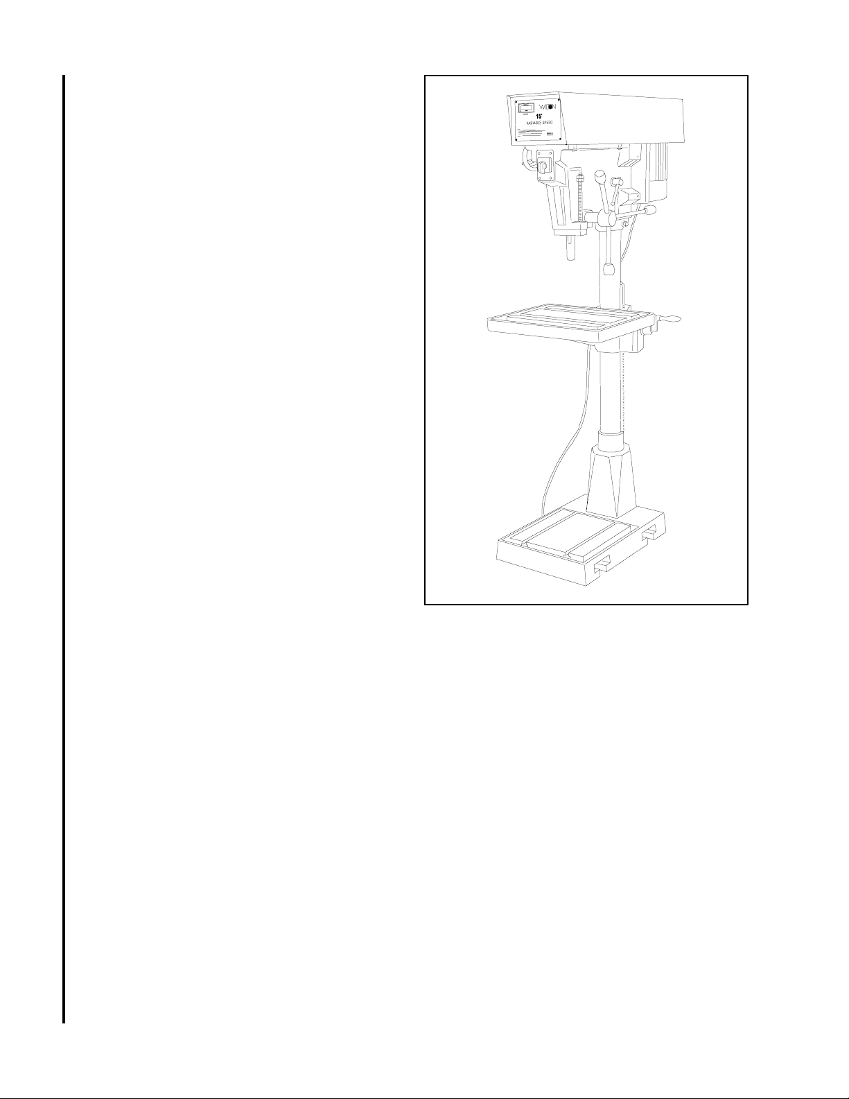
Introduction
Set-up and Operation
This manual includes operating and maintenance
instructions for the Wilton 15-Inch Vari-Speed Drill
Presses, Models A5816, A5818, A5836, and A5838.
This manual also includes parts listings and illustrations of replaceable parts.
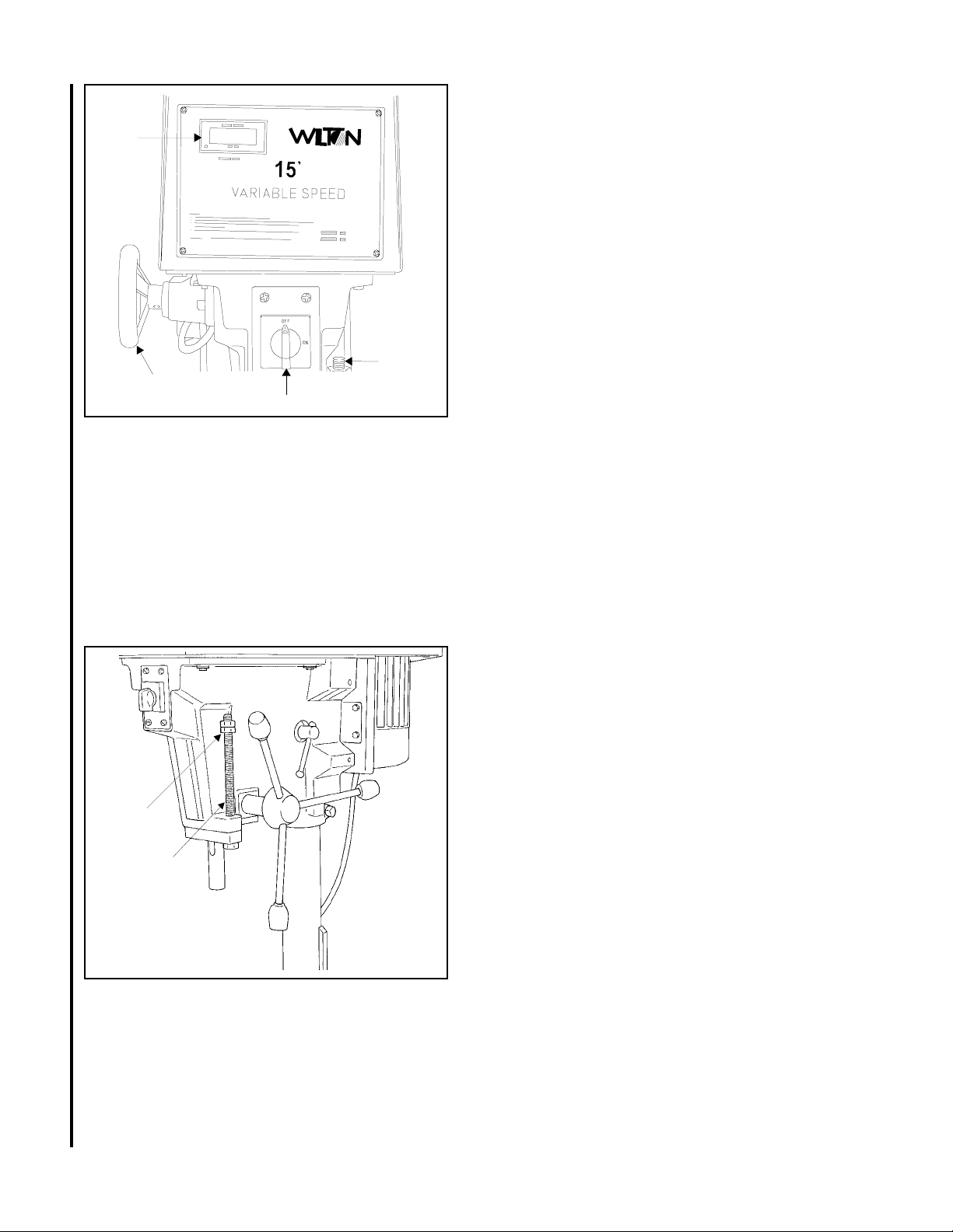
Refer to Figure 1 for key features of the drill press.
LED Speed
Display
Speed
setting
handwheel
On/Off
switch
Depth stop
Spindle
Feed
handle
Motor
Head
locking
handle
Column
Securing the Base
The base of the drill press has four mounting holes.
The drill press should be level and rest solidly on the
floor. Place shims under the four mounting holes in
the base as required to level the drill press.
Cleaning
Clean off any protective grease with solvent. After
cleaning, lubricate the base, table, and column with
a light coating of medium weight machine oil.
Repeat at six months intervals.
Internal parts of the drill press are lubricated at the
factory. No further lubrication is required at the time
of installation.
Electrical Connection
Refer to the Wiring Diagram section for wiring
information. Connection to electrical power should
be made by a qualified electrician. Observe local
electrical codes when connecting the machine.
The motor should be protected with a time delay
fuse or circuit breaker with a amperage rating
slightly higher than the full load current of the motor.
Work
table
Base
Figure 1: Drill Press Features
Table
height
adjustment
Rack
Operating Controls
(Refer to Figure 2)
ON/OFF Switch
The ON/OFF switch is located at the front of the drill
head.
Speed Control Handwheel
CAUTION: TO AVOID DAMAGE TO THE SPEED
ADJUSTMENT MECHANISM, THE MOTOR MUST
BE OPERATING BEFORE ATTEMPTING TO
ADJUST THE SPEED SETTING.
The speed control handwheel is located on the left
side of the drill head. An LED speed indicator is
provided on the face plate on the drill head.
7
Page 8
LED
Speed
Display
Depth
Speed control
handwheel
Figure 2. Operating Controls
On/Off switch
stop
Depth Stop
A drilling depth stop (refer to Figure 3) is provided on
the right side of the drill head. The depth stop
consists of a threaded rod with depth setting jam
nuts. The front side of the threaded rod has a depth
scale. The jam nuts are loosened and moved to the
desired depth on the scale. The upper jam nut is
then tightened against the lower nut.
Operating Precautions
The following operating and safety precautions must
be observed in order to avoid harm to the operator
or damage to the drill press.
1. The head assembly must be locked to the
column so the thrust produced by drilling will
not force the head assembly up the column.
2. The work table must be locked to the column
so it will not be forced down the column.
3. Be sure the belt is tightened to the proper
tension.
4. DO NOT start to drill the workpiece until
making certain the workpiece is held down
securely.
5. MAKE SURE THE DRIVE MOTOR IS RUN-
NING BEFORE turning the speed control
handwheel in either direction.
6. Point of operation protection is required for
maximum safety. This remains the responsibility of the user/purchaser since conditions differ
between jobs.
7. Make sure the drill is secured in the spindle or
check before attempting to use the drill press.
8. Make sure the spindle taper is clean and free
of burrs, scoring, and galling to assure maximum gripping.
Drilling Recommendations
Speeds for Drilling
The speed of a drill is usually measured in terms of
the rate at which the outer periphery of the tool
moves in relation to the work being drilled. The
Jam
nuts
8
Depth scale
(on threaded
rod)
Figure 3. Depth Stop
common term for this is Surface Feet per Minute
(SFM). The relationship of SFM is expressed in the
following formulas:
SFM = 0.26 X rpm X Drill Diameter (in inches)
RPM = 3.8 x ________SFM__________
Drill diameter (in inches)
In general, the higher the speed the shorter the drill
life. Operating at the low end of the speed range for
a particular material will result in longer life. The
most efficient speed for operating a drill depends on
many variables:
1. Composition and hardness of material.
2. Depth of the hole.
3. Efficiency of the cutting fluid.
4. Type and condition of the drilling machine.
5. Desired quality of the hole.
Page 9

6. Difficulty of set-up.
Indication of Extreme Speeds and Feeds
A drill that splits up the web is evidence of too much
feed or insufficient tip clearance at the center as a
result of improper grinding. The rapid wearing away
of the extreme outer corners of the cutting edges
indicates that the speed is too high. A drill chipping
or braking out at the cutting edges indicates that
either the feed is too heavy or the drill has been
ground with too much tip clearance.
3. Remove head cover.
4. Remove belt. (With speed control setting at the
highest speed, the belt should be loose enough
to remove.)
5. Install the replacement belt. Install the head
cover.
6. Connect electrical power to the drill press.
7. Operate the drill press to verify correct operation.
Replacement of Motor
Speeds for High Speed Steel Drills
Speed
Material In SFM
Alloy Steel — 300 to 400 Brinell .....................20 - 30
Stainless Steel................................................30 - 40
Automotive Steel Forgings .............................40 - 50
Tool Steel, 1.2C ..............................................50 - 60
Steel, .4C to .5C .............................................70 - 80
Mild Machinery Steel, .2C to .3C..................80 - 110
Hard Chilled Cast Iron ....................................30 - 40
Medium Hard Cast Iron ................................70 - 100
Soft Cast Iron .............................................100 - 150
Malleable Iron.................................................80 - 90
High Nickel Steel or Monel .............................40 - 50
High Tensile Bronze ......................................70 -150
Ordinary Brass and Bronze ........................200 - 300
Aluminum and its Alloys .............................200 - 300
Magnesium and its Alloys...........................250 - 400
Slate, Marble, and Stone.................................15 -25
Plastics and similar material (Bakelite).......100 - 150
Wood...........................................................300 -400
Titanium Alloys ...............................................10 - 25
Titanium Alloy Sheet.......................................50 - 60
WARNING: MAKE SURE TO DISCONNECT
ELECTRICAL POWER TO THE DRILL PRESS TO
AVOID THE POSSIBILITY OF INADVERTENT
OPERATION AND EXPOSURE TO POTENTIALLY
LETHAL VOLTAGE LEVELS.
1. Disconnect electrical power to drill press.
2. Remove drive belt (refer to Replacement of
Drive Belt).
3. Disconnect electrical wiring from motor junction
box.
4. Remove nuts and washers from bolts securing
motor to drill head. Remove motor.
5. Remove pulleys and related components from
motor shaft.
6. Install pulleys and related components on
replacement motor shaft.
7. Install motor on mounting bolts and secure with
nuts and washers.
8. Connect electrical wiring (refer to Wiring
Diagram section for wiring details).
9. Install drive belt (refer to Replacement of
Drive Belt).
10. Operate drill press to verify proper operation.
In cases where carbon steel drills are applicable, the
drill should be run at speeds of from 40 to 50
percent of those given above.
Maintenance
Replacement of Drive Belt
WARNING: MAKE SURE TO DISCONNECT
ELECTRICAL POWER TO THE DRILL PRESS TO
AVOID THE POSSIBILITY OF INADVERTENT
OPERATION AND EXPOSURE TO POTENTIALLY
LETHAL VOLTAGE LEVELS.
1. Start drill press. Set speed control to highest
speed. Stop drill press.
2. Disconnect electrical power to drill press.
9
Lubrication
Following are lubrication recommendations for drill
press components.
1. Spindle pulley drive: Lubricate spindle splines
occasionally with light grease.
2. Quill, Table, and Column: Lubricate with light
film of oil.
3. Table lift rack: Lubricate regularly with SAE20
oil (clean rack with solvent before applying oil.)
4. Variable speed drive fork: Lubricate contact
points occasionally with grease.
Page 10
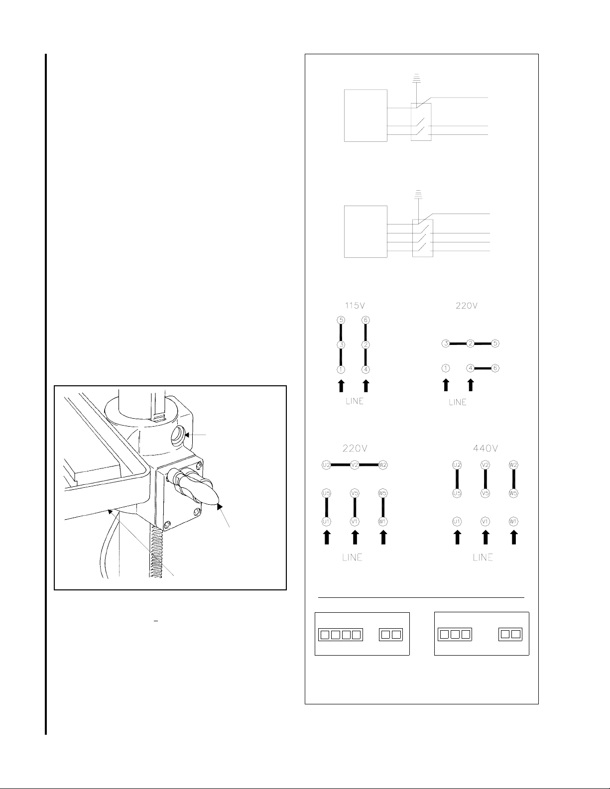
Adjustments
Table Adjustment
The table can be raised or lowered to accommodate
the height of the component being drilled (refer to
Figure 4). To raise or lower the table, loosen the
lock handle. Then use the hand crank to move the
table to the desired height. Then retighten the lock
handle.
Figure 4. Table Adjustment
Head Adjustment
WARNING: CHANGE THE RADIAL POSITION OF
THE DRILL HEAD ONLY IF THE DRILL PRESS
BASE IS SECURED TO THE FLOOR. SWINGING
THE DRILL HEAD WITHOUT THE BASE BEING
SECURED TO THE FLOOR WILL CAUSE THE
DRILL PRESS TO BECOME UNSTABLE AND TIP
OVER RESULTING IN INJURY AND/OR DAMAGE
TO THE MACHINE.
The radial position of the drill head can be changed
Motor
1 Phase 115/230 Volts
Motor
3 Phase 220/440 Volts
Switch
Switch
Green
Line
White
Black
Green
Line
10
Table lock
(handle on
opposite side)
Table
height
adjustment
Work table
to accommodate the drilling of a hole that may be
offset from the center of the table. Reposition the
drill head by loosening the locking handles and
swinging the drill head to the desired position. Then
retighten the locking handles.
Wiring Diagrams
Refer to Figure 5 for wiring information. The drive
motor is115/230 volt single phase or 220/440 volt
three phase. Notice: When converting machine
voltage, it is necessarry to re-wire the LED display
connection accordingly. Refer to figure 5.
1 phase Motor Connection
3 phase Motor Connection
AC Power Sensor
0 110 220 24
Volts
1 Phase 115/220
Figure 5. Wiring Diagrams
- +
Input
LED Display Connection
AC Power Sensor
0 220 440
Volts
3 Phase 220/440
- +
Input
Page 11

Troubleshooting
Problem Possible Cause Remedy
Spindle does not turn. 1. Circuit breaker tripped. 1. Reset circuit breaker.
2. Branch circuit breaker tripped or 2. Reset branch circuit breaker/replace
fuse blown. fuse.
3. Open wire in switch circuit. 3. Repair open circuit.
4. Defective switch. 4. Repair switch.
5. Broken drive belt. 5. Replace drive belt.
Spindle noisy. 1. Damaged spindle bearings. 1. Replace bearings.
2. Worn spline. 2. Replace spline.
Drill stalls. 1. Worn drive belt. 1. Check condition of belt. Replace
glazed or slipping on pulleys.
2. Excessive feed rate for size of drill and material 2. Reduce feed pressure or use
being drilled. cutting fluid.
3. No cutting fluid or improper cutting fluid. 3. Use correct cutting fluid.
Poorly drilled holes. 1. Drill dull. 1. Sharpen drill.
2. Lack of rigidity in hold-down method. 2. Check that all T-slot hold-downs are
tight and that table-lock and drill
head bolts are tight.
3. Speed too fast for material and drill size. 3.
Check spindle speed recommendations.
Reduce speed if
necessary.
4. Feed too fast for material and drill size. 4. Reduce feed rate.
5. No or improper cutting fluid or coolant 5. Use cutting fluid, or change to
being used. proper fluid or coolant for material
being drilled.
6. Improperly ground drill bit. 6. Check for proper angles and reliefs.
Regrind to proper geometry.
Motor overheating. 1. Electrical circuit fault. 1. Check current draw in circuit.
Make sure current draw is the
same as rating on motor plate.
2. Oversize drill. 2. Reduce drill size.
3. Excessive feed. 3. Reduce feed rate.
4. No cutting fluid, or wrong fluid. 4. Use correct cutting fluid for the
material and drill.
if
11
Table can not be 1. Lack of lubrication. 1. Lubricate.
raised.
No speed readout. 1. Speed pickup out of adjustment or failed. 1. Adjust gap between speed pickup
and post spindle pulley. If there is
no readout on the speed indicator,
replace the speed pickup.
Page 12

Replacement Parts
This section provides exploded view illustrations that show the replacement parts for the Wilton 15-Inch VariSpeed Drill Presses, Models A58 and A38 series. Also provided are parts listings that provide part number,
description, and quantity. The item numbers shown on the illustration relate to the item number on the facing
page of the parts listing.
Order replacement parts from:
Wilton Corporation
300 South Hicks Road
Palatine, IL 60067
TEL: 1-888-594-5866
FAX: 1-800-626-9676
Identify the replacement part by the part number shown in the parts listing. Be sure to include the model
number and serial number of your machine when ordering replacement parts to assure that you will receive the
correct part.
12
Page 13
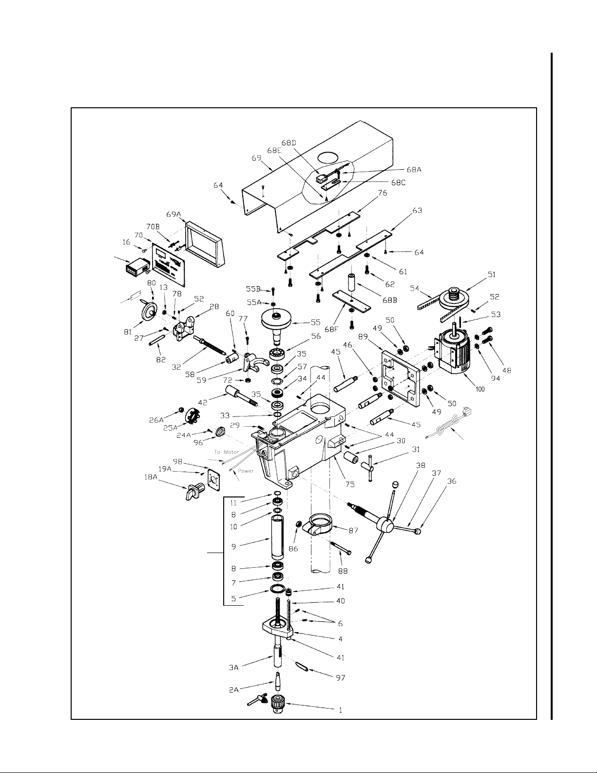
Exploded View — Head
Models: A5816, A5818, A5836, & A5838
70A
39
21
99
(Note 1)
17
17A
13
Page 14

Parts List - Head
Models A5816, A5818, A5836 and A5838
14
Item Part
No. Number Description Qty
1 5507580 Chuck (with Key) 1
2A 5507495 #2 MT x JT3 Arbor 1
3A 5507496 Spindle Assembly 1
4 5053070 Quill Band 1
5 9010541 O-Ring 1
6 905451 1 Set Screw 2
5/16-18 x 3/8
7 5032611 Bearing Retainer 1
8 9100331 Bearing 2
9 5041010 Quill 1
10 9058561 Wavy Spring Washer 1
11 9074081 Truarc Retainer 1
13 9056981 Hex Jam Nut 3
1/4-20
16 5518170 Sloted self taping Screw 5
3/16-24 x 3/8
17 5518157 Power Cord (1-Phase) 1
17A 5517463 Power Cord (3-Phase) 1
18A 5507500 Switch (Single Phase) 1
5507497 Switch (3-Phase) 1
19A 5507501 Slotted Machine Screw 4
1/4-20 x 1
21 5518158 Wiring Harness (1-Phase) 1
5517457 Wiring Harness (3-Phase) 1
24A 5507502 Socket Head Cap Screw 3
25A 5507503 Return Spring Assemlby 1
26A 5507504 Nylon Nut 1
27 9135311 Lock Screw 1/4-20 x 1 2
28 5041050 Speed Change Housing 1
29 9127731 Socket Set Screw 1
5/16-18 x 5/16
30 5024541 Head Lock (Plain Side) 1
31 1000771 Lock Nut Assembly 1
32 5041071 Speed Change Shaft 1
33 9053661 Retainer 1
34 5041201 Bearing Spacer 1
35 9100321 Bearing 2
36 9070291 Knob 3
37 5053000 Spoke 3
38 5507827 Feed Shaft Assembly 1
39 5513378 Hi/Lo Speed Direction Plate 1
40 5053100 Rod, Graduated 1
41 9056381 Jam Nut 5/8-11 3
42 9128611 Hex Head Cap Screw 1
1/2-12 x 4
44
TS-0270031 set Screw 4
5/16-18 x 3/8
45 5032781 Motor Plate Bar 4
46 9057111 Whiz Flange Locknut 4
47 TS-0152051 Carriage Bolt 5/16-18 x 2 4
48 9056171 Carriage Bolt 4
5/16-18 x 1-1/2
49 9058051 Split Lock Washer 1/2 ID 2
50 9056841 Hex Nut 1/2-12 2
51 5041170 Variable Speed Pulley (Motor) 1
52 9054621 Socket Set Screw 1/4-20 x 1/2 2
Item Part
No. Number Description Qty
53 5042011 Key (Motor) 1
54 9077101 Variable Speed Belt 1
55 5041140 Vaiable Speed Pulley (Spindle) 1
55A 5513510 Hex Nut 1
55B 5513511 SHCS 1
56 9100421 Bearing 1
57 9058571 Spring Washer 1
58 5041761 Speed Change Nut 1
59 5041040 Speed Change Lever 1
60 9127951 Socket Set Screw 1
1/4-20 x 1/2
61 9057461 Washer 1/4 3
62 9052101 Hex Head Cap Screw 4
1/4-20 x 1
63 5041271 Right Mounting Plate 1
64 5518170 Self T apping Screw 7
3/16-24 x 3/8
68A
68B 5513513 Spacer, Threaded 1
68C 5513514 Plate, Bracket 1
68D 5513515 Pickup, Magnetic 1
68E 5513516 Screw 2
68F 5513521 Plate 1
69 5041320 Cover, Pulley 1
69A 5513517 Bracket, Face Plate 1
70 5513518 Plate, Face 1
70A 5513519 LED Display 1Ph 1
70B 5513520 Screw, Locking 1
72 9056771 Hex Jam Nut 3/8-16 1
75 5041000 Head Casting 1
76 5518172 Left Mounting Plate 1
77 9052831 Socket Set Screw 1
78
80 9052971 Socket Set Screw 1
81 5034111 Hand Wheel 1
82 5513737 Shaft speed change lever 1
86 9129051 Hex Nut 7/16-14 1
87 5041470 Collar 1
88 9128071 Hex Head Cap Screw 1
89 5032560 Motor Mounting Bracket 1
94 TS-0680032 Washer 5/16 4
96 5507505 Return Spring Bracket 1
97 5507507 Drift Pin 1
98 5507506 Switch Mounting Plate 1
99 5507527 Quill Assembly (Note 1) 1
100 5507812 Motor, 1 PH 115/220
TS-0208041 SHCS 5/16-18x3/4 2
5513736 LED Display 3 Ph
3/8-16 x 1
TS-0267101 Socket Set Screw 1
1/4-20 x 1-1/4
5/16-18 x 5/16
7/16-14 x 3-1/2
1725 RPM 60 Hz 1
5514604 Motor, 1PH 115/220
1725 RPM 50 Hz 1
5507813 Motor, 3 PH 220/440
1725 RPM 50/60 Hz 1
Note 1: Quill assembly includes items 5, 7, 8, 9,10 and 11.
Page 15

Exploded View — Head
Models: A3816, A3818, A3836 & A3838
A
15
Page 16

Parts List - Head
Models: A3816, A3818, A3836 & A3838
16
Item Part
No. Number Description Qty
1 5507580 Chuck (with Key) 1
2A 5507495 #2 MT x JT3 Arbor 1
3A 5507496 Spindle Assembly 1
4 5053070 Quill Band 1
5 9010541 O-Ring 1
6 9054511 Set Screw 2
5/16-18 x 3/8
7 5032611 Bearing Retainer 1
8 9100331 Bearing 2
9 5041010 Quill 1
10 9058561 Wavy Spring Washer 1
11 9074081 Truarc Retainer 1
16 9052711 Self Tapping Screw 4
8-32 x 3/8
17 5518157 Power Cord (Single Phase) 1
17A 5517463 Power Cord (3-Phase) 1
18A 5507500 Switch (Single Phase) 1
5507497 Switch (3-Phase) 1
19A 5507501 Slotted Machine Screw 4
21 5518158 Wiring Harness (1-Phase) 1
5517457 Wiring Harness (3-Phase) 1
24A 5507502 Socket Head Cap Screw 3
25A 5507503 Return Spring Assemlby 1
26A 5507504 Nylon Nut 1
27 5518159 Phillips Screw 1/4-20 x 5/16 2
28 5518160 Cover Plate 1
29 9127731 Socket Set Screw 1
5/16-18 x 5/16
30 5024541 Head Lock (Plain Side) 1
31 1000771 Lock Nut Assembly 1
33 9053661 Retainer 1
34 5041201 Bearing Spacer 1
35 9100321 Bearing 2
36 9070291 Knob 3
37 5053000 Spoke 3
38 5507827 Feed Shaft Assembly 1
40 5053100 Rod, Graduated 1
41 9056381 Jam Nut 5/8-11 3
42 9128611 Hex Head Cap Screw 1
1/2-13 x 4
44 9052191 Socket Set Screw 4
5/16-18 x 1/2
45 5032781 Motor Plate Bar 4
46 9057111 Whiz Flange Locknut 4
48 9056171 Carriage Bolt 4
5/16-18 x 1-1/2
49 9058051 Split Lock Washer 1/2 ID 4
50 9056841 Hex Nut 1/2-13 4
51 5518161 Step Pulley (Motor) 1
52 5518162 Socket Set Screw 2
1/4-20 x 5/16
53 5042011 Key (Motor) 1
54 5518163 Drive Belt 1
55 5518164 Step Pulley (Spindle) 1
55A 5518165 Spindle Pulley Shaft 1
55B 5518166 Key 5 x 45 1
Item Part
No. Number Description Qty
57 9058571 Spring Washer 2
61 9057461 Washer 1/4 3
62 9052101 Hex Head Cap Screw 4
1/4-20 x 1
63 5518167 Mounting Plate 2
64 9138011 Self Tapping Screw 4
#10 x 3/4 Type A
69 5518168 Pulley Cover (w/door & latch) 1
70 5518169 Face Plate 1
75 5041000 Head Casting 1
86 9129051 Hex Nut 7/16-14 1
87 5041470 Collar 1
88 9128071 Hex Head Cap Screw 1
7/16-14 x 3-1/2
89 5032560 Motor Mounting Bracket 1
94 9055281 Rubber Washer 4
96 5507505 Return Spring Bracket 1
97 5507507 Drift Pin 1
98 5507506 Switch Mounting Plate 1
99 5507527 Quill Assembly (Note 1) 1
100 5507812 Motor, 1 PH 115/220
1725 RPM 60 Hz 1
5514604 Motor, 1PH 115/220
1725 RPM 50 Hz 1
5507813 Motor, 3 PH 220/440
1725 RPM 50/60 Hz 1
Note 1: Quill assembly includes items 5, 7, 8, 9, 10
and 11.
Page 17
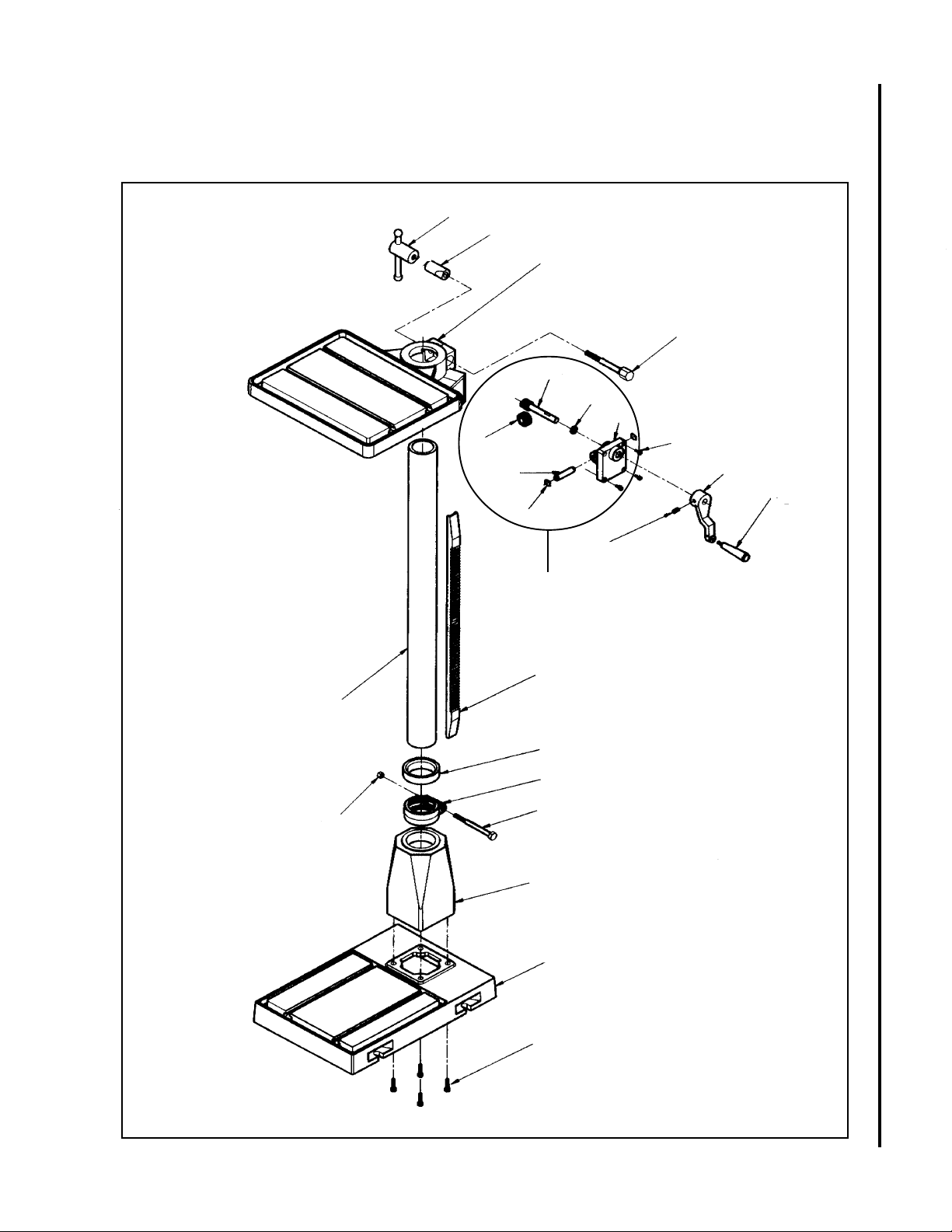
Exploded View - Base
(Floor Models A5816, A5818, A3816 & A3818)
1
2
3
14
13
12
15
18
4
16
17
19
25
22
9
23
6
5
7
20
21
17
10
11
8
Page 18

Parts List - Base
(Floor Models A5816, A5818, A3816 & A3818)
Item Part
No. Number Description Qty
1 1000771 Locknut 1
2 5003751 Table Lock (Plain Side) 1
3 5507508 Table 1
4 5507509 Hex Head Cap Screw 1
5 TS-0061091 Cap Screw 1
7/16-14 x 3-1/2
6 5041470 Collar 1
7 9129051 Hex Nut 7/16-14 1
8 5507528 Base 1
9 5507510 Standard Column 1
5511850 Short Column 1
10 5507511 Flange (Base/Column) 1
11 5630771 HHCS 1/2-12 x 1-1/2 4
12 5507571 Cover Plate 1
13 5507570 Bushing 1
14 5507513 Worm, Table Raiser 1
15 5507514 Gear, Table Raiser 1
16 5507515 Shaft, Table Raiser 1
17 5507516 C-Ring, Table Raiser 2
18 TS-0050051 SHCS 1/4 x 1 4
19 5507518 Socket Head Set Screw 1
5/16-18 x 3/8
20 5507519 Crank, T able Raiser 1
21 5507520 Handle, Table Raiser 1
22 5507521 Rack 1
23 5507522 Rack Ring 1
25 5507816 Table Raiser Assembly 1
18
Page 19

Page 20

WMH Tool Group, Inc.
2420 Vantage Dr.
Elgin, IL 60123
Ph: 847-649-3010
Fax:
847-851-1144
 Loading...