

Page 1

WARNING:Read and understand
all instructions. Failure to follow all
instructions may result in electric
shock, fire, and/or serious injury.
For your safety
10" Compound
Miter Saw
Models 99192 and 99195
Operation
and Safety
Instructions
Model 99192 shown
®
Page 2

IMPORTANT INFORMATION
2
TABLE OF CONTENTS
INTRODUCTION
Your new Wilton®10-inch Compound Miter Saw is a
rugged, dependable tool that will cut wood and other
materials at straight and compound angles with
extreme accuracy and repeatability. Easy to operate,
it’s the ideal saw for the serious Do-It-Yourselfer.
Take time to read these Operation and Safety
Instructions. Athorough understanding of your saw
will enable you to use it to its full potential.
SPECIFICATIONS
LASER LIGHT
Laser module...........S&S 1984S6; fixed focus, elliptical
dot with line beam lenses
Laser type.......................................................Class III A
Laser power..........................................up to 5mW MAX
Laser wavelength................................................635 nm
MITER SAW
Model numbers...................................99192 and 99195
Power source..............120V AC, 60 Hz, 15 A, 2 3/4 Hp
Speed .............................................................5000 RPM
Blade diameter..........................................10" (40 tooth)
Arbor size...................................................5/8” (16 mm)
Crosscut at 0˚, 0˚ bevel.............................2 3/4 x 5 1/2"
Miter at 45° miter, 0˚ bevel........................2 3/4 x 3 1/2"
Bevel 0° miter, 0° bevel.............................1 7/8 x 4 3/4"
Compound at 45°, 45° bevel.....................1 7/8 x 3 1/2"
Miter detent stops...........0, 15, 22.5, 30, 45° right & left
Positive stops............0, 15, 22.5, 31.6 & 45° left & right
Bevel................................................................0, 45° left
Dust collection...........................................................Yes
Net weight..............................................39 lbs (17.7 kg)
LIMITED WARRANTY
Wilton Power Tools are warranted against defects in workmanship and material for a period of two (2) years from the date of purchase.
This warranty does not cover defects due directly or indirectly to misuse, abuse, negligence or accidents, normal wear-and-tear,
improper repair or alterations, lack of maintenance, or use for purposes other than those for which the tool was designed. This
warranty does not cover products used for commercial, industrial or educational purposes. Any return must be preauthorized, so
please contact our Consumer Relations Department with warranty claims at 1-800-274-6848 for further instructions. If it is determined
that the product is within this warranty, replacement parts or complete product replacement will be made at our discretion.
WMH TOOL GROUPTMLIMITS ALL IMPLIED WARRANTIES TO THE PERIOD OF THE LIMITED WARRANTY FOR EACH PRODUCT.
EXCEPT AS STATED HEREIN, ANY IMPLIED WARRANTIES OF MERCHANTABILITYAND FITNESS ARE EXCLUDED. SOME
STATES DO NOTALLOW LIMITATIONS ON HOW LONG THE IMPLIED WARRANTY LASTS, SO THE ABOVE LIMITATION MAY
NOT APPLY TO YOU.
WMH TOOL GROUPTMSHALL IN NO EVENT BE LIABLE FOR DEATH, INJURIES TO PERSONS OR PROPERTY, OR FOR
INCIDENTAL, CONTINGENT, SPECIAL, OR CONSEQUENTIAL DAMAGES ARISING FROM THE USE OF OUR PRODUCTS. SOME
STATES DO NOTALLOW THE EXCLUSION OR LIMITATIONS OF INCIDENTAL OR CONSEQUENTIAL DAMAGES, SO THE ABOVE
LIMITATION OR EXCLUSION MAY NOT APPLY TO YOU.
IMPORTANT INFORMATION ....................................2
Introduction..........................................................2
Specifications.......................................................2
LIMITED WARRANTY...............................................2
SAFETY General Safety Warnings............................3
Special Safety Rules for Miter Saws...................4
Special Safety Rules for the Laser......................6
Electrical Requirements .......................................6
BEFORE YOU START...............................................8
Know Your Miter Saw..........................................8
Unpacking the Miter Saw.....................................9
ASSEMBLY..............................................................10
Woodworking Terms..........................................10
Assembling the Miter Saw.................................10
Installing Extension Wings.................................10
Release the Handle ...........................................11
Blade-to-Fence Adjustment................................11
Base-to-Blade Adjustment.................................12
Bevel Stop Adjustment......................................13
Mounting the Saw..............................................13
OPERATION ............................................................14
Body and Hand Positions..................................14
Supporting the Workpiece .................................14
Using Carbide Tipped Blades ............................14
Changing the Blade...........................................14
Miter Cut............................................................16
Align Laser Pointer with Blade ..........................16
Cutting Bowed Material .....................................17
Bevel Cut...........................................................17
Compound Cut...................................................17
Cutting Base Molding ........................................17
Cutting Crown Molding ......................................18
MAINTENANCE .......................................................19
SERVICE..................................................................20
Page 3

SAFETY
3
Read, understand and follow all operating instructions,
safety operations and symbols in this manual and
warning labels on the miter saw before operating,
maintaining, and cleaning your power tool.
Indicates the presence of a hazardous
situation which WILL cause serious injury or
death.
WARNING:
Indicates the presence of a hazardous
situation which CAN cause SEVERE personal injury.
CAUTION:
Indicates the presence of a hazardous situation
which WILL or CAN cause MINOR or MODERATE PERSONAL
injury, or could cause machine damage.
Note:
Indicates installation, operation, or maintenance
information which is important but not hazard-related.
GENERAL SAFETY WARNINGS
WARNING:
Failure to read all instructions and follow the
general safety warnings and other safety warnings and
cautions may result in serious personal injury.
Know your power tool – read the instruction manual.
Understand your power tool’s application, limitations,
and potential hazards.
Ground all tools – this tool is equipped with a
3-prong plug. It must be plugged into a properly
grounded receptacle.
Keep safety guards in place – and in working order
with proper adjustment and alignment.
Keep work area clean – prevent accidents. Take time
to clean the tool, the work area, and especially the
floor. The floor can become slippery from sawdust,
wax and other materials.
Avoid dangerous environments – do not use power
tools in damp or wet environments. Select a work area
with proper lighting.
Keep children away – from the work area. Children
and others should be a safe distance from the work
area.
Make the workshop childproof – use padlocks and
master switches. Remove starter keys from power
tools when not in use.
Do not force the tool – beyond its designed rate. For
a better and safer job, allow the tool to work within
manufacturer’s recommendation.
Use the right tool – for the job. Do not force a tool or
its attachments to perform a task that it is not designed
to do.
Wear the proper apparel – and non-slip footwear
when operating power tools. Do not wear loose
clothing, gloves, neckties, rings, bracelets or other
jewelry which may become caught in moving parts.
Keep long hair away from your face and tied back. Roll
long sleeves above the elbow.
Use safety goggles at all
times – which comply with
ANSI Z87.1. Normal safety
glasses only have impact
resistant lenses and are not
designed for safety. Wear a
face or dust mask when
working in a dusty environment. Use ear protection,
such as plugs or muffs, during extended periods of
operation.
Secure your work – using clamps or a vise when
practical. It frees both hands and is safer to operate
the tool.
Don’t overreach – and keep proper balance and
footing at all times.
Maintain your tools with care – keeping them clean
for best and safest performance.
Disconnect your tool – unplug the power cord from
the electrical source when making adjustments,
changing parts, cleaning, or working on the tool.
Avoid accidental starting – by ensuring the ON/OFF
switch is in the OFF position and the power cord is
unplugged from the electrical outlet.
Use recommended accessories – by the tool’s
manufacturer. Read, understand and follow the
instructions supplied with accessories. Using incorrect
accessories may be hazardous.
Never stand on the tool – or store materials above or
near it. Standing on the tool to reach materials could
result in serious injury if it tips or is accidentally
contacted.
Check any damaged parts – discontinue using a
damaged tool until the part is carefully checked.
Ensure that all parts will operate and perform properly.
Check for alignment of moving parts, jamming,
breakage, improper mounting, and any other condition
that may affect the tool’s operation. Any part that is
damaged should be properly repaired or replaced
before use.
SAVE THESE SAFETY INSTRUCTIONS
DANGER
Page 4

Never leave the tool unattended while it’s
running – turn OFF the power. Do not leave the tool
unattended until it reaches a complete stop.
Drugs, Alcohol, Medication – are not to be used
when operating the tool.
Wear a face mask or dust mask – when sawing.
Some dust created by power sanding, sawing,
grinding, drilling, and other construction activities
contain chemicals known to cause cancer, birth
defects, or other reproductive harm. Examples of
these chemicals include:
– Lead from lead-based paints
– Crystalline silica from bricks, cement, and other
masonry products
– Arsenic and chromium from chemically treated
lumber.
To reduce your exposure to these chemicals: work in
a well-ventilated area, use approved safety
equipment, and use dust masks that are specially
designed to filter out microscopic particles.
SPECIAL SAFETY RULES FOR
MITER SAWS
WARNING:
Do not operate or plug in your miter saw
until it is completely assembled and installed according to the
instructions. Read and understand the following operating
instructions and safety warnings in the manual and on the miter
saw.
Before Operating Your Miter Saw
Check for proper assembly and proper alignment of
moving parts.
Understand the function and proper use of:
●
Trigger switch/start button
●
Lower blade guard
●
Miter locks
●
Bevel lock knob
●
Handle latch
●
Arbor lock
Know the condition of your miter saw. If any part is
missing, bent, or does not operate properly, replace
the component before you continue to use your saw.
Determine the type of work you are going to be doing
before you operate your saw. Properly protect your
body including your eyes, hands, face, and ears.
Avoid injury from jams, slips, or thrown pieces
●
Use the correct 10-inch blade for the material and
type of cut. Do not cut materials which shatter, grab
the blade, or cause other danger.
●
The arrow on the blade must correspond with the
arrow on the upper blade cover. When you are
facing the front of the saw, teeth on the blade
should point downward.
●
Only use a sharp blade that is in good condition.
Check alignment of the blade after it is installed.
Unplug the saw and carefully spin the blade using
your hand. The blade should not contact any
components of the saw. If it does, correct the
problem before operating the saw.
●
Make sure the blade and blade collars are clean
and the blade collar is properly installed.
●
Make sure the arbor bolt is properly installed and
tightened.
●
Ensure all clamps and locks are tight. Verify there is
no excessive play in any parts.
●
Allow the blade to reach full speed before cutting.
Do not cut freehand
●
The workpiece should be tight against the fence.
Verify the workpiece will not rock or twist when it is
being cut. The area between the workpiece and the
saw must be free from debris.
●
Make sure there is no gap between the workpiece,
fence, and base of the saw. Agap could allow the
workpiece to move when it is being cut.
●
Use clamps, fixtures or other devices to hold an
unstable workpiece. Do not secure waste piece.
Do not cut more than one workpiece at a time
●
Allow room so the cut-off workpiece can move after
it is cut. It could create a hazard by becoming
wedged against the blade.
Be very careful when cutting odd shaped,
extremely large, or very small workpieces
●
Plan your work so an odd shaped workpiece cannot
slip or pinch the blade. When cutting material like
molding, it must lie flat or be held by a fixture. Do
not allow the material to rock, twist, or slip.
●
Secure sagging workpieces with saw horses, tables
or other additional supports.
●
Do not cut small workpieces that must be held
closer than 4 inches (102 mm) from the blade.
●
Properly support round material when cutting.
Dowel rods and tubing have a tendency to roll while
being cut. This could allow the blade to “bite” into
the material causing a hazardous condition. Hold
round material in place using clamps or other
fixtures.
SAFETY
4
SAVE THESE SAFETY INSTRUCTIONS
Page 5

SAFETY
5
●
Inspect the workpiece for nails or other foreign
objects before it is cut.
●
Do not allow anyone to stand behind the saw or
close to the workpiece where debris can be thrown.
●
Operate your saw in a clear, safe environment.
Avoid contact with a rotating blade
●
Do not wear gloves, loose clothing, or jewelry.
●
Tie back long hair and roll long sleeves above the
elbow.
Avoid injury from accidental starting of saw
●
Unplug the power cord from the electrical source.
●
Disconnect the lower blade guard.
●
Install or remove the blade.
●
Perform maintenance or make adjustments.
Avoid injury from electrical shock
●
Do not touch the metal blades on the power cord
plug when inserting or removing the plug from an
electric outlet.
Avoid injury from a fire hazard
●
Do not operate the saw near flammable liquids,
vapors, or gases.
When Operating Your Miter Saw
Avoid injury from unexpected saw movement
●
Use the saw on a firm level surface with adequate
space for handling and supporting the workpiece.
●
Be sure the saw cannot move when operated.
Secure the saw to a workbench or table with heavy
duty screws, washers, and nuts.
Before moving the saw
●
Unplug the power cord from the electrical source.
●
Lock the handle in the down position using the
handle latch.
Avoid back injury
●
Obtain help when it is necessary to raise the saw
more than 10 inches (254 mm).
●
Bend your knees when lifting the saw.
●
Carry your saw by the carrying handle or base. Do
not carry your saw by the power cord or the trigger
handle. Carrying the saw by the power cord could
cause damage to the insulation or the wire
connections resulting in electric shock or fire.
Whenever Your Miter Saw is Running
WARNING:
• Do not make a careless error just because you operate the
saw frequently. Aneglectful moment can cause a severe injury.
• Do not lubricate the blade while it is spinning.
Prior to cutting a workpiece
●
Test the operation of your saw. If you feel excessive
vibration or hear an unusual noise, immediately
stop operating the saw. Correct the problem before
using.
Allow movement of the waste portion of the
workpiece
●
Do not hold it, clamp it, touch it or use a length stop
against it. The cut-off waste portion must be free to
move. It could become wedged against the blade
causing a hazard.
Avoid awkward operation
●
Make sure your hand is never closer than 4 inches
from the blade.
●
Do not cross your arms in front of the blade while
operating the saw.
Do not force the blade through the workpiece
●
Lower the blade through the workpiece fast enough
to allow the blade to cut without binding or bogging
down.
Before removing obstructed material
●
Release the trigger switch/start button, wait for the
blade to stop moving, and unplug the power cord
from the electric outlet.
After completing a cut
●
Keep the handle in the down position. Release the
trigger switch/start button and wait for the blade to
stop moving.
SAVE THESE SAFETY INSTRUCTIONS
Page 6

SPECIAL SAFETY RULES FOR
THE LASER
Laser light - do not stare into beam,
aperture, or into a reflection from a
mirror-like surface.
Avoid exposure - laser radiation is
emitted from top rear of the guard
housing aperture.
Do not disassemble laser module.
The laser is a CLASS III A laser
product that can emit laser power up to 5 mW MAX at
635 nm, which could result in exposure with the
module disassembled. The laser unit complies with
21 CFR 1040.10 and 1040.11.
Use of controls or adjustments or
performance of procedures other than
those specified in this manual may result in hazardous
radiation exposure.
ELECTRICAL REQUIREMENTS
WARNING:
• Use only manufacturer’s recommended replacement parts, or
equivalent, when servicing this tool.
• Do not touch the metal blades on the power cord plug when
removing or installing the plug into an electrical outlet.
• To avoid electrical hazards, fire hazards, or damage to the
tool, use proper circuit protection.
Your miter saw is wired at the factory for 120V
operation. Connect to a 120V, 15 AMP time delayed
fuse or circuit breaker. To avoid shock or fire, replace
power cord immediately if it is worn, cut, or damaged in
any way.
Use a separate electrical circuit for your tools.
This circuit must not be less than a #12 wire and
should be protected with a 15 Amp time delayed fuse.
Before connecting the motor to the power line, make
sure the switch is in the OFF position and the electric
current is rated the same as the current stamped on
the motor nameplate. Running at a lower voltage will
damage the motor.
Do not modify the power cord plug. If it does not
match the electrical outlet, have the proper outlet
installed by a qualified electrician.
This tool is intended for use on a circuit that has a
receptacle like the one illustrated: a 3-prong electrical
plug (1) and a receptacle (2) that has a grounding
conductor. If a properly grounded receptacle is not
available, have a certified electrician check the
receptacle.
SAFETY
6
SAVE THESE SAFETY INSTRUCTIONS
DANGER
DANGER
DANGER
DANGER
1
2
Page 7

SAFETY
7
In the event of a malfunction or breakdown,
grounding provides the path of least resistance for
electric current and reduces the risk of electric shock.
This tool is equipped with an electric cord that has an
equipment grounding conductor and a grounding plug.
The plug MUST be plugged into a matching
receptacle that is properly installed and grounded in
accordance with ALL local codes and ordinances.
Improper connection of the equipment grounding
conductor can result in risk of electric shock. The
conductor with the green insulation (with or without
yellow stripes) is the equipment grounding conductor.
If repair or replacement of the electric cord or plug is
necessary, DO NOT connect the equipment
grounding conductor to a live terminal.
Check with a qualified electrician or service personnel
if you do not completely understand the grounding
instructions, or if you are not sure the tool is properly
grounded.
WARNING:
This miter saw is for indoor use only. Do
not expose to rain or use in damp locations. This tool must be
grounded while in use to protect the operator from electrical
shock.
Guidelines for Extension Cords
Use proper extension cord. Make sure your
extension cord is in good condition. When using an
extension cord, be sure to use one heavy enough to
carry the current your product will draw. An undersized
cord will cause a drop in line voltage, resulting in loss
of power and cause overheating. The table below
shows the correct size to use depending on cord
length and nameplate ampere rating. If in doubt, use
the next heavier gauge. The smaller the gauge
number, the heavier the cord.
Use only 3-wire extension cords that have 3-prong
plugs and 3-prong outlets that accept the tool’s plug.
Be sure your extension cord is properly wired and
in good operating condition. Always replace a
damaged extension cord or have it repaired by a
qualified person before using it.
Protect your extension cords from sharp objects,
excessive heat and damp or wet areas. Repair or
replace damaged or worn cord immediately.
SAVE THESE SAFETY INSTRUCTIONS
Minimum Gauge for Extension Cords (AWG)
(when using 120 volts only)
Ampere Rating Total Length of Cord in Feet (meters)
More Than Not More Than 25 (7.6) 50 (15.2) 100 (30.4) 150 (45.7)
0 6 18 16 16 14
6 10 18161412
10 12 16 16 14 12
12 16 14 12 Not Recommended
Page 8

BEFORE YOU START
8
KNOW YOUR MITER SAW
Figure 1
1 Power switch handle
2 Lower blade guard
3 Fence
4 Extension wing assembly
5 Miter handle
6 Miter index scale
7 Clamp vise assembly
8 Mounting hole
9 Blade wrench storage
10 Dust bag
11 Laser module
12 Power switch
13 Safety lock-out button (model 99192)
14 Laser switch
15 Dust port
16 Handle stop lock
17 Bevel lock knob
18 Bevel index scale
1
2
3
4
4
5
6
7
8
9
10
11
12
13
14
1
13
11
15
16
17
18
Model 99192
Model 99195
1
2
3
4
4
5
6
7
8
9
10
11
14
1
12
11
15
16
17
18
Page 9

BEFORE YOU START
9
UNPACKING THE MITER SAW
WARNING:
To avoid injury:
• Do not plug the power cord into the power source during
unpacking or assembly.
• If any part is missing or damaged, do not connect the miter saw
to the power source until the missing or damaged part is
replaced and assembly is complete.
• Avoid fire and toxic reaction. Never use gasoline, naphtha,
acetone, lacquer, thinner or any volatile solvents to clean the
miter saw.
1. Carefully unpack the compound miter saw and all
its components.
2. Inspect the contents and compare to the list below.
1 Compound miter saw with laser line
assembly
2 Vise clamp knob
3 Dust bag
4 Miter handle
5 Blade wrench
6 Extension wings (2)
7 Bar holder clamp (4)
8 Stop bracket
Figure 2
2
1
Model 99192 shown
Page 10

ASSEMBLY
10
WOODWORKING TERMS
Arbor – shaft which mounts the cutting tool.
Bevel cut – angle cut made through the face a
workpiece.
Compound cut – bevel cut and miter cut
simultaneously.
Crosscut – cut made across the width of the workpiece.
Freehand – a cutting operation without using the
support of the fence or other means to hold the
workpiece. Freehand is not recommended.
Kerf – amount of material removed by a blade in a
through cut, or the slot produced by the blade in a
partial cut.
Miter cut – angle cut made across the width of the
workpiece.
Revolutions per minute (RPM) – number of turns
completed by a spinning object in one minute.
Saw blade path – part of the workpiece which will be
cut, or workpiece directly in line with travel of blade.
Set – distance between two tips of the saw blade
teeth, bent outward in opposite directions to each
other.
Workpiece – material being cut.
ASSEMBLING THE MITER SAW
Your miter saw requires these minor assembly tasks.
Once assembled, complete the adjustment
procedures before using the saw.
Installing the miter handle
1. Thread the miter lock handle (1) into the hole
located at the front of the miter table.
2. Tighten.
Figure 3
Saw Blade wrench
1. Store the blade wrench (1) in the slot at the rear of
the saw to prevent loss.
Figure 4
INSTALLING EXTENSION WINGS
AND WORKPIECE STOP
The extension wings support long workpieces during
cutting. The adjustable stop bracket attaches to a rail
of a wing. The stop bracket can be raised or lowered
and moved toward or away from the saw as needed.
The extension wings and stop bracket should be
installed prior to mounting the saw on a workbench or
table.
1. Lock the bevel and miter handles in the down
position.
2. Tilt the saw back to gain access to the underside of
the base. Secure the saw so that it will not tip or fall
off the workbench.
3. Slide the stop bracket (1) onto the rear rail of one of
the extension wings (2). Secure the wing screw (3)
that holds the stop bracket in place.
Figure 5
1
2
3
4
5
6
7
1
Page 11

ASSEMBLY
11
4. Insert both rails of an extension wing through the
first set of holes (4) on the outside of the saw base.
5. Place a bar holder clamp (6) over each rail.
Figure 6
6. Slide the rails through the second set of holes (6)
until the rails rest against the base of the saw (7).
Make sure the bar holder clamps rest against the
outside wall (10) of the saw base.
7. Tighten the screws (8) that secure the bar holder
clamps to the rails. Make sure the extension wing
does not move and turn the lock nuts (9) clockwise
to prevent the screw from loosening.
8. Repeat steps 4 through 7 to install an extension
wing on the other side of the saw.
9. Place the saw in the upright position on the
workbench.
WARNING:
Make sure the power cord is unplugged
from the power source and you have read and understood the
safety and operating instructions.
Verify the following adjustments to ensure cutting
accuracy.
Note: Avoid touching the saw teeth with the square.
The set in the blade’s teeth will hold the square away
from the blade.
RELEASE THE HANDLE
(Figure 7)
The handle latch secures the handle position in the
down position.
•
Never operate your saw with the handle in the
DOWN position.
•
Always store and transport your saw with the
handle locked in the DOWN position.
Figure 7
To raise the handle:
1. Push down on the saw handle.
2. Pull out the handle stop latch (1).
3. Allow the handle to rise to the up position.
To lock the handle:
1. Push the saw handle down to the lowest position.
2. Push in the handle latch (1) to lock the cutting head
in the down position.
BLADE-TO-FENCE ADJUSTMENT
(Figures 8 & 9)
Make sure the blade is square to the fence.
1. Push the handle latch in to lock the handle in the
down position.
2. Hold a combination square (1) against the fence (2)
and next to the blade (3). The blade should contact
the full length of the square.
Figure 8
3. If the blade does not contact the full length of the
square, loosen the four fence screws (4) using a
6 mm wrench.
8
9
10
1
3
2
15
225
30
45
1
Page 12

ASSEMBLY
12
Figure 9
4. Hold the square against the blade. Move the fence
until it contacts the full length of the square.
5. Slightly tighten screws, then tighten screws (4)
alternately.
Note: The combination square and the wrench shown
in Figures 8 and 9 are not provided.
BASE-TO-BLADE ADJUSTMENT
(Figures 10, 11, and 12)
Make sure the blade is perpendicular to the base.
1. Push the handle latch in to lock handle in the down
position. Tighten the bevel lock handle.
2. While lowering the blade, hold a combination
square (1) against the base (2) and next to the
blade (3). Avoid touching the saw teeth with the
square. The set in the blade's teeth will hold the
square away from the blade. The blade should
contact the full length of the square.
Figure 10
3. If the blade does not contact the full length of the
square, loosen the bevel adjustment screw (4). Hold
the square against the base. Rotate the bevel
adjustment screw (5), up or down, until the full length
of the square is against the blade.
Figure 11
4. Tighten the bevel adjustment screw.
Figure 12
5. Make sure the bevel indicator (6) is aligned with the
bevel index 0° mark. Loosen the bevel indicator
screw (5) and move it to align with the 0° mark if
adjustment is needed.
6. Tighten the bevel indicator screw.
4
4
3
15
225
30
45
2
5
1
Page 13

ASSEMBLY
13
BEVEL STOP ADJUSTMENT
(Figure 13)
Make sure the bevel indicator aligns with the bevel
index 45° mark when the handle assembly is against
the bevel stop adjustment screw. If adjustment is
necessary:
Figure 13
1. Loosen the bevel stop adjustment screw lock nut
(1) using a 10 mm wrench.
2. Rotate the bevel stop adjustment screw (2), up or
down, until the bevel indicator aligns with the bevel
index 45° mark.
3. Tighten the bevel stop screw lock nut (1).
MOUNTING THE SAW
Before operating your saw, it must be firmly mounted
to your workbench or other rigid frame.
WARNING:
Reduce the risk from unexpected saw
movement:
•
Unplug the power cord from the power source.
•
Lock the handle in the down position before moving your saw.
•
Carry your saw close to your body to avoid injury to your back.
Bend your knees when lifting the saw.
•
Carry your saw by the handle or the base. Do not carry your
saw by the power cord or the trigger handle. Carrying the saw
by the power cord could cause damage to the insulation or the
wire connections resulting in electric shock or fire.
•
Secure the saw in a position where people cannot stand, sit or
walk behind it. Debris thrown from the saw could injure people
standing, sitting or walking behind it.
•
Secure the saw to a firm level surface where the saw cannot
rock and there is adequate room for handling and properly
supporting the workpiece.
Figure 14
To secure the saw to a work surface:
1. Set the saw on the surface and mark the location of
the four holes (1).
2. Remove the saw and predrill the holes.
3. Secure the saw to the work surface.
•
Use wood screws if mounting to wood.
•
Use bolts, washers, and nuts if mounting to metal.
PORT ABLE APPLICATIONS
Once properly secured, the saw may be mounted to a
portable surface.
To mount the saw to a portable surface:
1. Secure your saw to a 3/4 inch piece of plywood.
Make sure the plywood is large enough to hold the
saw and to allow the use of clamps.
2. Clamp the plywood to sawhorses or a portable
workbench.
Note: The plywood mounted to your saw can also
help protect it from damage when transporting it.
1
Page 14
OPERATION
14
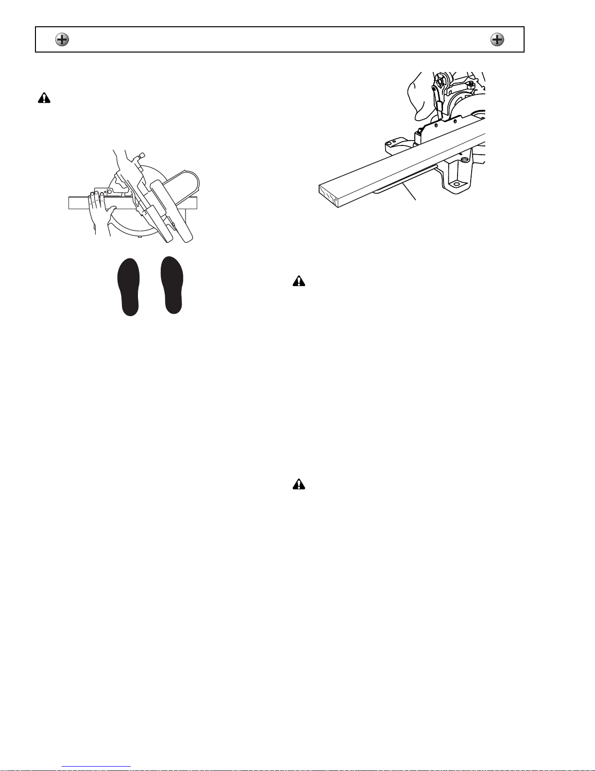
BODY AND HAND POSITIONS
WARNING:
Do not cut short workpieces. You cannot
properly hold a short workpiece and have your hand a safe
distance from the blade. Never cross your arms or place your
hands near the cutting area.
Figure 15
1. Position your body and hands with the saw to make
cutting easier and safer. Keep your face and body
to one side of the blade, out of line with a possible
debris throwback.
2. Don’t overreach; keep good footing and balance.
Place your hand away from the blade at least
4 inches (102 mm).
3. Hold the workpiece firmly against the fence and
keep hands in position until the trigger has been
released and the blade has completely stopped.
Before making a cut, make a “dry run” with the
power off to determine the path of the blade.
SUPPORTING THE WORKPIECE
Support long workpieces to prevent sagging. Use the
extension wings (1) to support long workpieces.
The extension wings will allow the workpiece to lie
flat on the entire length of the saw's base.
Figure 16
USING CARBIDE TIPPED BLADES
WARNING:
Read, understand and follow all warnings
and instructions provided with your carbide tipped blades.
Handle carbide tipped blades carefully. Carbide is very
brittle and can be easily damaged. Use caution when
you install, use, and store your blades.
Do not use a carbide tipped blade that is bent or has
bent teeth, or if the blade has cracks, broken, missing
or loose carbide tips.
Do not operate a carbide tipped blade faster than its
maximum recommended speed.
CHANGING THE BLADE
(Figures 17 – 21)
WARNING:
•
Before changing a blade, unplug the power cord from the power
source. The power cord must be unplugged whenever you are
working on your saw.
•
To avoid injury from a thrown workpiece, do not use a blade
larger or smaller than 10" (25.4 cm).
•
Do not use a dull saw blade. Additional force is required to
operate, making it unsafe.
Immediately replace the blade if it shows signs of
deterioration or damage. Dull or damaged blades can
cause personal injury and ineffective operation of your
saw.
1
Page 15

OPERATION
15
To replace the blade:
1. Loosen the guard plate screw (1).
Figure 17
2. Rotate the lower blade guard up to expose the
arbor bolt (2).
Figure 18
3. While pushing in on the arbor lock (3) to hold the
blade in position, turn the arbor bolt clockwise using
the socket wrench supplied with your saw.
Note: turn the arbor bolt clockwise to loosen and
counterclockwise to tighten.
Figure 19
4. Remove the arbor bolt, outer blade collar, and
blade.
Figure 20
5. Clean any sawdust from both blade collars before
installing the blade. Install a 10" (25.4 cm) blade
only. Verify the rotation arrow on the blade matches
the cast-in rotation arrow on the upper blade guard.
make sure the blade is behind the flange.
6. Install the outer blade collar (4) and arbor bolt (5).
While pushing in on the arbor lock, turn the arbor
bolt counterclockwise to tighten.
Figure 21
7. Rotate the lower blade guard and guard plate
down until the plate is behind the forward plate
screw. Tighten both guard plate screws.
8. Slightly raise the lower guard plate until the screw
and bushing can be threaded into the brass nut.
Tighten the screw and make sure the busing is
centered in the lever slot.
1
Page 16
OPERATION
16
MITER CUT
To make a miter cut, loosen the miter lock handle.
Move the handle to the desired angle. Tighten the
miter lock handle. Position your body in line with the
miter angle to make the cut. Do not stand in front of
the saw.
WARNING:
• Do not cross your arms in front of the blade while operating the
saw.
• Be sure both miter locks are tightened before you operate the
saw.
1. Unlock the miter handle (1) by turning
counterclockwise.
2. Turn the miter table (2) to the degree of angle
desired.
3. Tighten the miter handle to lock the table in position
before beginning the cut.
4. Position your body in line with the miter angle to
make the cut. Do not stand in front of the saw.
Figure 22
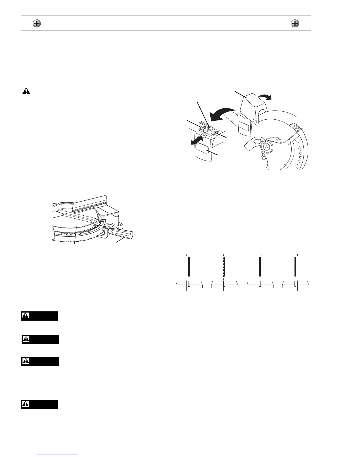
ALIGN LASER POINTER WITH
BLADE
The laser pointer must be aligned with the blade to
ensure an accurate cut.
Laser light - do not stare into beam,
aperture, or into a reflection from a
mirror-like surface.
Avoid exposure - laser radiation is
emitted from top rear of the guard
housing aperture.
Do not disassemble laser module.
The laser is a CLASS III A laser
product that can emit laser power up to 5 mW MAX at
635 nm, which could result in exposure with the
module disassembled. The laser unit complies with
21 CFR 1040.10 and 1040.11.
Use of controls or adjustments or
performance of procedures other than
those specified in this manual may result in hazardous
radiation exposure.
1. Make sure the safety lock-out button and the laser
switch are in the OFF position.
2. Put a padlock on the power switch to make sure the
blade does not start.
3. Plug in the power cord and turn on the laser switch.
4. Remove the laser module cover (1).
Figure 23
5. Loosen, but do not remove the two laser module
screws (2).
6. Move the laser module (3) to the left or right until it
is aligned properly with the left or right side of the
blade. See Figure 24
7. Tighten the laser module screws and replace the
cover and remove the padlock.
Note: Turn the laser switch to the OFF position
when not in use.
Figure 24
MAINTAIN LASER MODULE
Inspect and remove dust from the laser module as
needed. See Figure 23.
1. Turn the saw and laser switches to the OFF
position and unplug the saw.
2. Remove the cover from the laser module.
3. Slide out the laser lens cover (4) and clean it with a
soft, clean cloth. Do not use solvents of any type as
they may damage the lens.
4. Remove dust from the laser module with a soft,
clean cloth.
5. Replace the laser module cover.
2
3
1
2
4
DANGER
DANGER
DANGER
DANGER
2
1
INCORRECT INCORRECTCORRECT CORRECT
Page 17

17
CUTTING BOWED MATERIAL
Inspect your workpiece before cutting it. If it is bowed,
position the workpiece against the fence with the bow
facing as illustrated.
WARNING:
Failure to cut a bowed workpiece as
described above may result in the blade becoming pinched. This
could result in the workpiece moving suddenly, causing personal
injury .
Figure 25
BEVEL CUT
To make a bevel cut, loosen the bevel lock handle.
Rotate the blade to the desired bevel angle and lock
into position. Stand to the left side of the handle to
make the cut.
Figure 26
COMPOUND CUT
To make a compound cut, select the correct miter and
bevel angles. Lock the blade into position. Move your
feet and body in line with the handle to the desired
miter angle to make the cut.
Figure 27
CUTTING BASE MOLDING
Base moldings and trims can be cut on a compound
miter saw. The method depends on the type of
molding, its characteristics and applications.
Figure 28
1. Use vise clamps, hold-down, or C-clamps
whenever possible. Place tape on the area being
clamped to avoid marking the finish surface of the
molding.
2. Tape the area being cut to avoid splintering, and
mark the cut line on the tape.
3. Perform practice cuts on scrap pieces before
cutting the final molding.
Note: Splintering may be caused due to the thinness
of the molding g or use of the wrong type of blade.
OPERATION
2
1
CORRECT INCORRECT
F
e
n
c
e
Mitre saw table
Mitre at 45o, bevel at 0
F
e
n
c
e
o
Mitre saw table
Mitre at 0o, bevel at 45
o
Page 18

CUTTING CROWN MOLDING
Crown molding must be compound mitered with
extreme accuracy. The two surfaces on the crown
molding must fit the wall or ceiling, and each other.
The two cut surfaces of the mitered molding must add
to a 90° angle. Most crown molding has a top angle of
52° that fits flat on the ceiling, and a bottom rear angle
of 38° that fits flat against the wall.
1. The crown molding is thin and cannot stand
vertically on edge. Lay the molding flat with its
widest back surface flat on the saw table.
Figure 29
2. To avoid splintering and marking, tape the cutting
line and any surface that is being clamped.
3. The angle settings for the two pieces of molding
that will be adjoining in any one corner will be
interdependent with each other. Any change in
setting for one side must be equally compensated
for on the other side.
Figure 30
4. All settings should be tested on scrap material
before cutting the actual molding.
OPERATION
18
KEY
IL 33.9°
31.6°
Right
1. Position top of molding against fence.
2. Miter table set at RIGHT 31.6°.
3. LEFT side is finished piece.
IR 33.9°
31.6°
Left
1. Position bottom of molding against fence.
2. Miter table set at LEFT 31.6°.
3. LEFT side is finished piece.
OL
33.9°
31.6°
Left
1. Position bottom of molding against fence.
2. Miter table set at LEFT 31.6°.
3. RIGHT side is finished piece.
BEVEL
SETTING
MITER
SETTING
Inside corner - Left side
Inside corner - Right side
O
utside corner - Left side
Outside corner - Right side
TYPE OF CUT
OR
33.9°
31.6°
Right
1. Position top of molding against fence.
2. Miter table set at RIGHT 31.6°.
3. RIGHT side is finished piece.
F
e
n
c
e
Mitre saw table
Workpiece lying flat
Inside corner
IR
IL
Compound cut crown mouldings
OL
OR
Outside corner
Page 19

19
WARNING:
●
Before performing any maintenance or cleaning on your saw,
unplug the power cord from the power source. The power cord
must remain unplugged whenever you are working on your
saw.
●
To prevent electrical shock, fire or injury, use only identical
replacements parts with equivalent characteristics, including
type, strength and material. Be sure to assemble replacement
parts exactly as the original components to reduce the risk of
electrical shock.
●
If the power cord is worn, cut or damaged, have it replaced
immediately.
SAWDUST
WARNING:
Wear eye protection when using air
pressure to clean your saw.
WARNING:
Dust generated from certain materials can
be hazardous to your health. Always operate the miter saw in
well-ventilated areas and provide proper dust removal. Use
dust collection systems whenever possible. Wear a face mask
when operating the miter saw.
Empty the sawdust bag regularly. Keep sawdust
accumulation around and under your saw to a
minimum. Use compressed air or a vacuum to keep
the area clean.
INSPECT LOWER BLADE GUARD
Regularly inspect the lower blade guard to ensure it
operates properly. Do not operate your saw with a
damaged or missing lower blade guard. The lower
blade guard is installed for your safety.
Keep the lower blade guard free of sawdust buildup
and clean. Use a damp cloth to remove dust from the
lower blade guard.
WARNING:
Be sure to unplug the power cord from the
power source before cleaning the lower blade guard.
Note:
To prevent damage to the lower blade guard, clean it only
with a damp cloth. Using solvent on it can cause damaged to the
plastic.
LUBRICATION
All the ball bearings are permanently lubricated and do
not require lubrication.
CLEANING AND STORAGE
Clean any dust or debris which may accumulate.
Apply a light coat of automotive wax to the table to
keep it clean and make it easier to move the
workpiece. Keep the handle in the DOWN position
during storage.
REPLACING CARBON BRUSHES
(Figure 31)
WARNING:
Be sure to unplug the power cord from the
power source before inspecting the carbon brushes.
Figure 31
Check the condition of the carbon brushes after
50 hours of use. If the brushes are worn to 1/16 inch
(2 mm) in length, replace them.
To inspect the carbon brushes:
1. Remove end cap (1) to expose brushes. Carefully
clean any dust or debris present.
2. Carefully remove the spring (2) and brush (3),
taking note of their location and position.
3. Inspect the brush and replace if necessary. Be
sure to replace both brushes even if only one is
damaged.
Note:
If you are not installing new brushes, be sure to reinstall the brushes in the same position they were removed
from.
4. Position the brushes into the motor.
5. Reinstall end cap.
MAINTENANCE
2
1
3
Page 20

FOR REPLACEMENT PARTS AND SERVICE
When servicing your Wilton®product, use only Wilton®replacement parts. Use of any other parts may cause
product damage. All servicing of the tool should be performed by a qualified service technician. When
requesting service or ordering parts, always provide the model number, part number and description.
In the U.S.: WMH TOOL GROUP
Consumer Relations
427 Sanford Road
Lavergne, TN 37086
Phone: 1-800-274-6846 (technical assistance)
1-800-274-6848 (parts)
www.wmhtoolgroup.com
In Canada: WMH TOOL GROUP LTD
Customer Service
212A Wilkinson Road
Brampton, Ontario L6T 4M4 CANADA
Phone: 1-800-689-9928
www.wmhtoolgroup.com
20
SERVICE
Customer Replacement Parts
Part Number Item
99164N001 Bevel lock knob
99164N008 Bolt to secure fence (set of 2)
99164N009 Washer for fence bolt (set of 2)
99164N010 Fence
99164N011 Screws to secure table insert (set of 3)
99164N012 Table insert
99164N022A Extension wings (set of 2) with 4 holders
99164N026A Bar holder clamp with screw (set of 2)
99164N028A Stop bracket with screw
99164N034 Miter index grip
99164N035 Miter lock handle
99164N056A Lower guard with plate
99164N051 Lower guard return spring
99164N050 Return spring cover
99164N055 Guard/spring assembly screw
99164N049 Guard/spring assembly washer
99164N048 Guard/spring assembly lock nut
99164N054A Guard cover screw and washer
99164N116 Lower guard rubber bumper
99164N117A Bumper screw and washer
99164N128 Lower guard arm
99164N071 Motor brushes (set of 2)
99164N072 Brush covers (set of 2)
99164N135 Dust bag
99164N086 Dust chute
99164N102 Blade wrench
99164N124 Blade flanges (set of 2)
99164N127 Blade bolt
M99192 Manual
M99192 A0804 ©WMH Tool Group Printed in China
 Loading...