

Page 1
Operating Instructions — Parts Manual
20-Inch VS Drill Press
Models: 2221VS, 2223VS, 2232AC, 2234AC
Serial Number 201001 and greater
WHM TOOL GROUP
2420 Vantage Drive
Elgin, Illinois 60124 Part No. 5510374
Ph.: 800-274-6848 Revision D6 08/06
www.wmhtoolgroup.com Copyright © WMH Tool Group
Page 2

Page 3

Table of Contents
Cover Page....................................................................................................... 1
General Specifications ...................................................................................... 4
Operating Precautions ...................................................................................... 5
Operation and Set-up ........................................................................................ 7
Operating Controls ............................................................................................ 8
Maintenance ................................................................................................... 10
Machine Adjustments ...................................................................................... 11
Wiring Diagram ............................................................................................... 13
Troubleshooting............................................................................................... 15
Accessories .................................................................................................... 16
Replacement Parts.......................................................................................... 17
3
Page 4
General Specifications
The Wilton 20 Inch Variable Speed Drill presses
Models 2221VS, 2223VS, 2232AC, and 2234AC are
available in manual speed control or inverter speed
control configuration. Electrical power options are
single-phase, 115 and 220 volts, or 3-phase, 440
volts.
Specifications
Manual Speed Control Models Inverter Speed Control Models
2221VS 2223VS 2232AC 2234AC
Drilling Capacity
Cast Iron .............................................. 1-1/4 In. ................. 1-1/4 In. ....................1-1/2 In. ................. 1-1/2 In.
Steel .................................................... 1 In. ....................... 1 In. ..........................1-3/8 In. ................. 1-3/8 In.
Spindle to Table (Max.) ................................. 32-3/8 In. ............... 32-3/8 In. .................. 32-3/8 In. ............... 32-3/8 In.
Spindle to Base (Max.) ................................ 44-1/2 In. ............... 44-1/2 In. ..................44-1/2 In. ............... 44-1/2 In.
Spindle to Column (Max.) ............................ 10-7/16 In. ............. 10-7/16 In. ................ 10-7/16 In. ............. 10-7/16 In.
Motor
Rating .................................................. 2 hp, 1-Phase ........ 2 hp, 3-Phase .......... 2 hp, 3-Phase .......2 hp, 3-Phase
Voltage ................................................ 115/220 V .............. 220/440V ..................220V...................... 440V
Pre-wired Voltage ................................ 115 V ..................... 220V ........................220V ...................... 440V
T-Slots (Table/Base)
Number ............................................... 2............................ 2 ..............................2 ............................ 2
Size ..................................................... 5/8 In. .................... 5/8 In. ....................... 5/8 In. .................... 5/8 In.
Column Diameter ........................................ 4-1/2 In. ................. 4-1/2 In. .................... 4-1/2 In. ................. 4-1/2 In.
Spindle
Travel .................................................. 6 In. ....................... 6 In. .......................... 6 In. ....................... 6 In.
Taper ................................................... MT-3 ...................... MT-3.........................MT-3 ......................MT-3
RPM (Variable) .................................... 300-2000 ............... 300-2000 .................. 65-2000 ................. 65-2000
4
Quill
Diameter ............................................. 3 In. ....................... 3 In. ..........................3 In. ....................... 3 In.
Travel .................................................. 6 in. ....................... 6 in. .......................... 6 in. ....................... 6 in.
Table
Overall ................................................. 22x18-3/4 In. .......... 22x18-3/4 In. ............22x18-3/4 In. .......... 22x18-3/4 In.
Working Surface .................................. 18-1/8x14-3/4 ........ 18-1/8x14-3/4 ...........18-1/8x14-3/4 ........ 18-1/8x14-3/4
Travel .................................................. 32-3/8 In. ............... 32-3/8 In. .................. 32-3/8 In. ............... 32-3/8 In.
Base
Overall ................................................. 26x19 In. ................ 26x19 In. ..................26x19 In. ................ 26x19 In.
Working Surface .................................. 15-1/4x12-1/16 ...... 15-1/4x12-1/16 ......... 15-1/4x12-1/16 ...... 15-1/4x12-1/16
Overall Dimensions
Length ................................................. 34-1/4 In. ............... 34-1/4 In. .................. 36-5/8 In. ............... 36-5/8 In.
Width ................................................... 27 In. ..................... 27 In. ........................27 In. ..................... 27 In.
Height .................................................. 77-1/4 In. ............... 77-1/4 In. ..................82-1/4 In. ............... 82-1/4 In.
Weight
Net ...................................................... 715 lbs.(325 kgs) ... 715 lbs.(325 kgs) .....715 lbs.(325 kgs) ... 715 lbs.(325 kgs)
Gross .................................................. 803 lbs.(365 kgs)... 803 lbs.(365 kgs) .....792 lbs.(360 kgs) ... 792 lbs.(360 kgs)
1. All work shall be secured using either clamps or a vise to the drill press table. It is unsafe to use your hands
to hold any workpiece being drilled.
Page 5

- Misuse of this machine can cause serious injury.
- For safety, machine must be set up, used and
serviced properly.
- Read, understand and follow instructions in the
Operating Instructions and Parts Manual which
was shipped with your machine.
supply while servicing.
- Always follow instructions in Operating Instructions
and Parts Manual when changing accessory tools
or parts.
- Never modify the machine without consulting
Wilton Corporation.
When setting up machine:
- Always avoid using machine in damp or poorly
lighted work areas.
- Always be sure the machine support is securely
anchored to the floor or the work bench.
When using machine:
- Always wear safety glasses with side shields (See
ANSI Z87.1)
- Never wear loose clothing or jewelry.
- Never overreach—you may slip and fall.
When servicing machine:
- Always disconnect the machine from its electrical
You—the stationary power tool user—
hold the key to safety.
Read and follow these simple rules for best results
and full benefits from your machine. Used properly,
Wilton’s machinery is among the best in design and
safety. However, any machine used improperly can
be rendered inefficient and unsafe. It is absolutely
mandatory that those who use our products be
properly trained in how to use them correctly. They
should read and understand the Operating Instructions and Parts Manual as well as all labels affixed to
the machine. Failure in following all of these warnings
can cause serious injuries.
Machinery general safety warnings
1. Always wear protective eye wear when operating
machinery. Eye wear shall be impact resistant,
protective safety glasses with side shields which
comply with ANSI Z87.1 specifications. Use of
eye wear which does not comply with ANSI Z87.1
specifications could result in severe injury from
breakage of eye protection.
2. Wear proper apparel. No loose clothing or
jewelry which can get caught in moving parts.
Rubber soled footwear is recommended for best
footing.
3. Do not overreach. Failure to maintain proper
working position can cause you to fall into the
machine or cause your clothing to get caught —
pulling you into the machine.
4. Keep guards in place and in proper working
order. Do not operate the machine with guards
removed.
5. Avoid dangerous working environments. Do not
use stationary machine tools in wet or damp
locations. Keep work areas clean and well lit.
6. Avoid accidental starts by being sure the start
switch is “OFF” before plugging in the machine.
7. Never leave the machine running while unat-
tended. Machine shall be shut off whenever it is
not in operation.
8. Disconnect electrical power before servicing.
Whenever changing accessories or general
maintenance is done on the machine, electrical
9. Maintain all machine tools with care. Follow all
10. Machinery must be anchored to the floor.
11. Secure work. Use clamps or a vise to hold work,
12. Never brush away chips while the machine is in
13. Keep work area clean. Cluttered areas invite
14. Remove adjusting keys and wrenches before
15. Use the right tool. Don’t force a tool or attach-
16. Use only recommended accessories and follow
17. Keep hands in sight and clear of all moving parts
18. All visitors should be kept at a safe distance from
19. Know the tool you are using — its application,
power to the machine must be disconnected
before work is done.
maintenance instructions for lubricating and the
changing of accessories. No attempt shall be
made to modify or have makeshift repairs done to
the machine. This not only voids the warranty but
also renders the machine unsafe.
when practical. It is safer than using your hands
and it frees both hands to operate the machine.
operation.
accidents.
turning machine on.
ment to do a job it was not designed for.
manufacturers instructions pertaining to them.
and cutting surfaces.
the work area. Make workshop completely safe
by using padlocks, master switches, or by
removing starter keys.
limitations, and potential hazards.
5
Page 6

General electrical cautions
This drill press should be grounded in accordance with the National Electrical Code and local codes and
ordinances. This work should be done by a qualified electrician. The saw should be grounded to protect the
user from electrical shock.
Wire sizes
Caution: for circuits which are far away from the electrical service box, the wire size must be increased in
order to deliver ample voltage to the motor. To minimize power losses and to prevent motor overheating and
burnout, the use of wire sizes for branch circuits or electrical extension cords according to the following table is
recommended.
AWG (American wire gauge) number
Conductor length 240 volt lines 120 volt lines
0-50 feet No. 14 No. 14
50-100 feet No. 14 No. 12
Over 100 feet No. 12 No.8
Safety Instructions for Drill Presses
handling any sharp objects or cutting tools. See
2. Drill press head and table shall be securely
locked to the column before operating the drill press.
This must always be checked prior to starting the
machine.
3. Always use the correct tooling. Tooling shall
always be maintained and properly sharpened. All
tooling must be run at the proper speeds and feeds
as they apply to the job. Use only recommended
accessories and follow those manufacturers instructions pertaining to them. Tooling shall be not be
forced in to any workpiece but fed according to the
proper specifications. Failure to follow these
instructions will not only ruin the tooling as well as
the machine, but can cause serious injury.
Figure A.
6. Always wear protective eye wear when operating,
servicing or adjusting machinery. Eyewear shall be
impact resistant, protective safety glasses with side
shields complying with ANSI Z87.1 specifications.
Use of the eye wear which does not comply with
ANSI Z87.1 specifications could result in severe
injury from breakage of eye protection. Figure B.
7. When drilling in material which causes dust, a
dust mask shall be worn. See Figure C.
8. Avoid contact with coolant, especially guarding the
eyes.
4. Never brush away any chips while the machine
6
is in operation. All clean up should be done when
the machine is stopped.
5. Keep hands in sight. Do not put hands or
fingers around, on, or below any rotating cutting
tools. Leather safety gloves should be used when
A B C
9. Non-slip footwear and safety shoes are recommended. See Figure D.
10. Wear ear protectors (plugs or muffs) during
extended periods of operation. See Figure E.
D E
Page 7
Introduction
This manual includes operating and maintenance
instructions for the Wilton Model 2221VS, 2223VS,
2232AC and 2234AC Variable Speed Drill Presses.
This manual also includes parts listings and illustrations of replaceable parts.
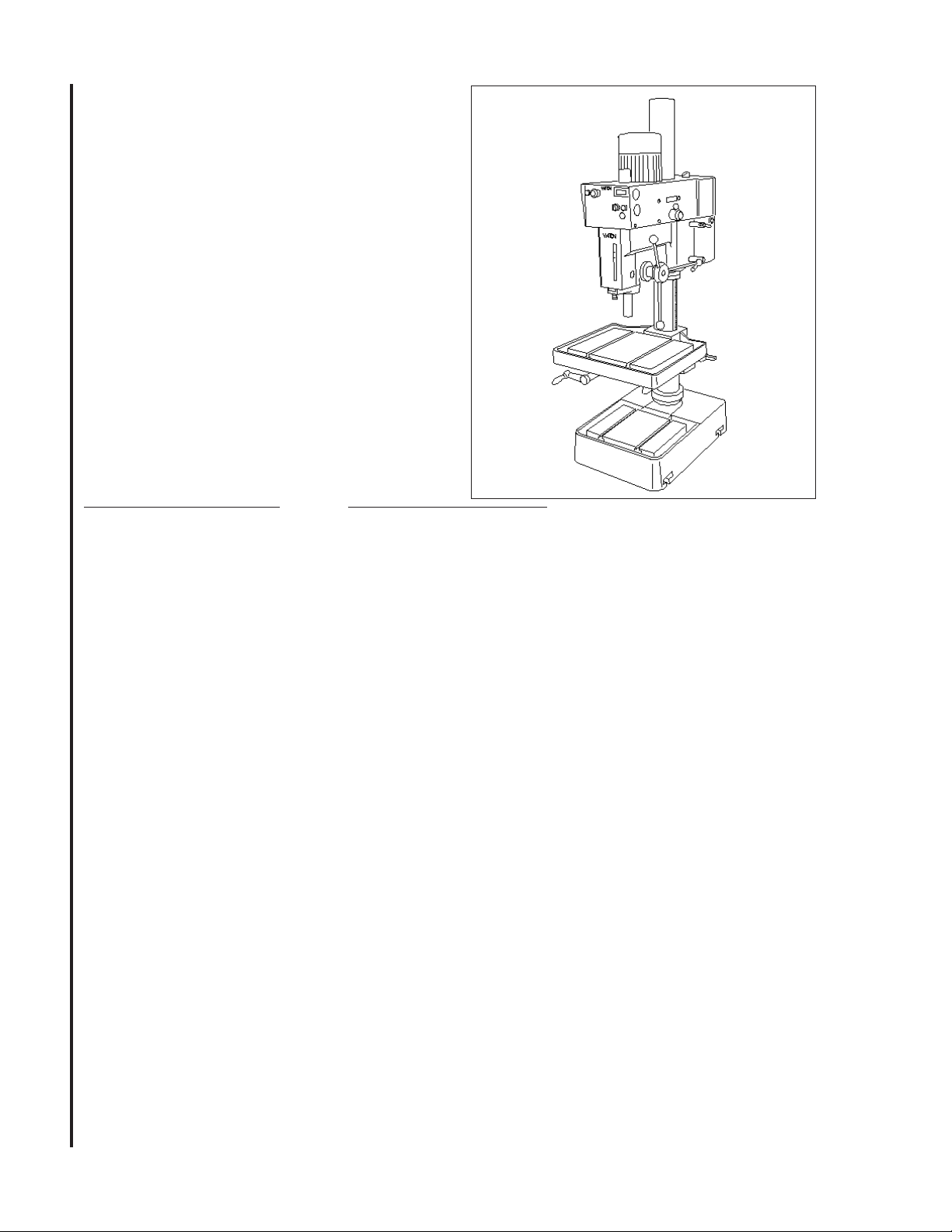
Operation and Set-up
Securing the Base
Wilton Model 2221VS and 2223VS drill presses
feature manual speed control. Models 2232AC and
2234AC have inverter speed control. This manual
contains procedures for both speed control versions.
The manual provides separate instructions when
differences in operation and maintenance exist.
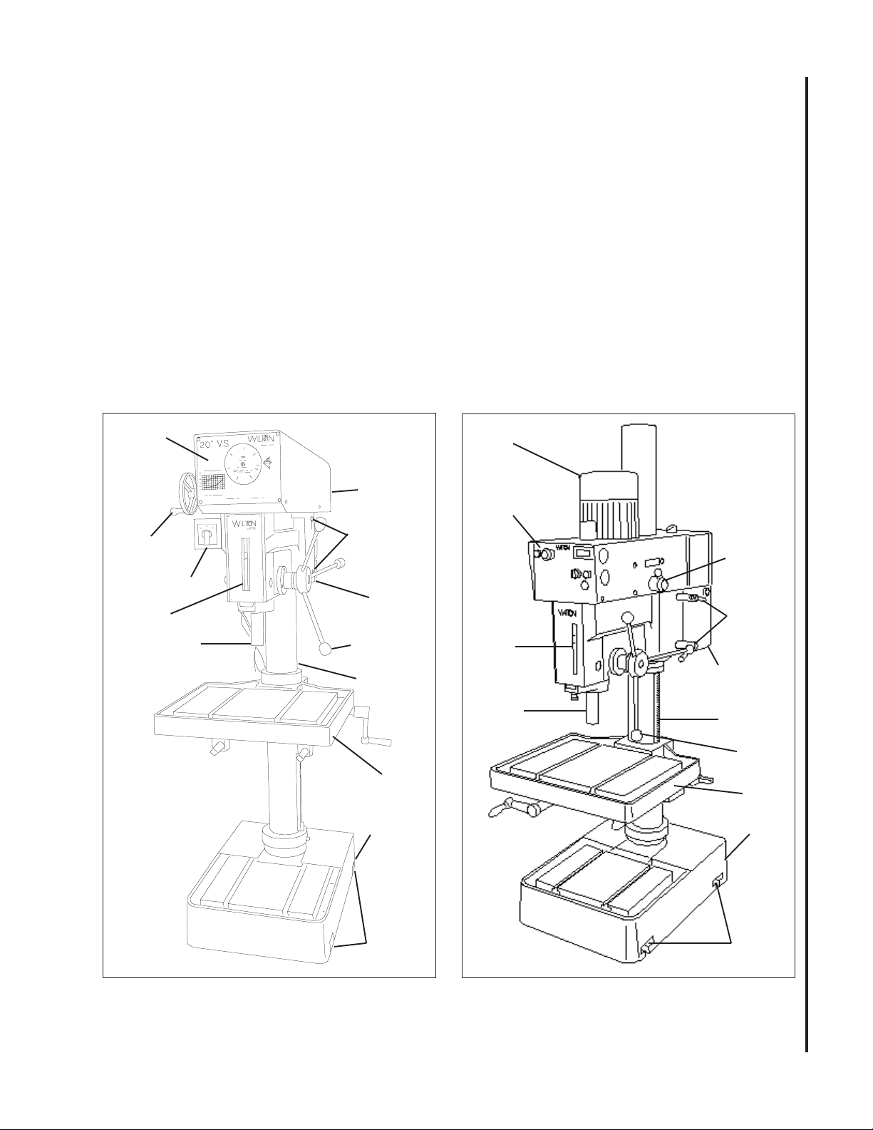
Refer to Figures 1 and 2 for key features of the drill
press.
Control
Panel
Speed
Adjustment
Handwheel
Switch
Depth
Indicator
Spindle
Electrical
Enclosure
(hidden, far
side)
Drill
Head
Head
Clamping
Nuts (2)
Drive
Motor
Spindle
Handle
Column
The base of the drill press has four mounting slots;
two slots on both sides of the base. The drill press
should be level and rest solidly on the floor. Place
shims under the four mounting slots in the base as
needed to level the drill press.
When securing the base to the floor, apply even
torque to the fasteners to prevent distortion of the
base.
Drive
Motor
Control Panel
Speed
Shift Lever
Head
Clamping
Depth
Indicator
Spindle
Nuts (2)
Electrical
Enclosure
Column
Figure 1: Drill Press Features
(Manual Speed Control Model)
Work
Table
Base
Mounting
Slots (4)
Figure 2: Drill Press Features
(Inverter Speed Control Model)
Spindle
Handle
Work
Table
Base
Mounting
Slots (4)
7
Page 8
Raising the Drill Head and
Table
The drill press is shipped with the table and drill head
supported by wooden blocks near the bottom of the
column.
The head is raised to the operating position using a
strap and hoist, then secured to the column by
tighening the hex cap screw . The table is raised to
the desired position using the crank handle.
Electrical Connection
Refer to the Wiring Diagram section for wiring
information.
A selector switch is provided at the left side of the drill
head. The two-position switch is used to start and
stop the drive motor.
Speed Control Handle
CAUTION: TO AVOID DAMAGE TO THE SPEED
ADJUSTMENT MECHANISM, THE DRIVE MOTOR
MUST BE OPERATING BEFORE ATTEMPTING TO
ADJUST THE SPEED SETTING.
Models 2221VS (manual control) and 2232AC
(inverter control) are pre-wired for 115 volts. Models
2223VS (manual control) and 2234AC (inverter
control) are pre-wired for 220 volts.
Connection of electrical power should be made by a
qualified electrician. Observe local electrical codes
when connecting the machine.
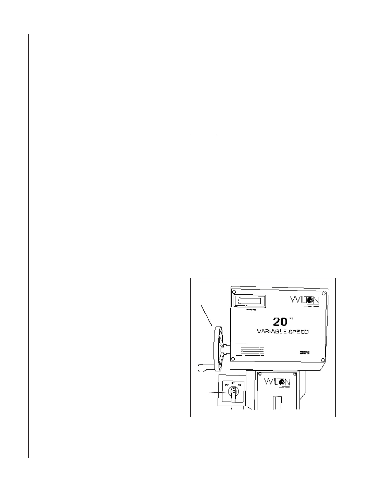
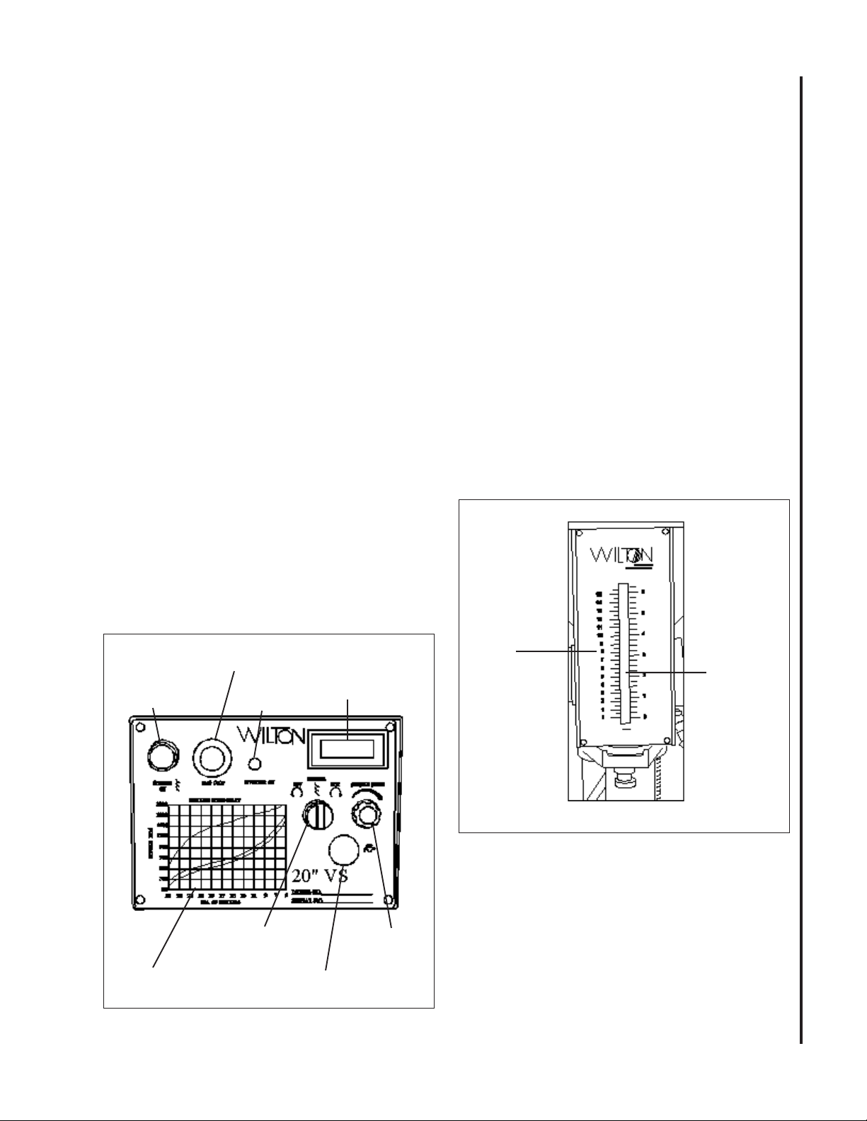
Operating Controls
(Refer to Figures 3, 4, and 5)
Manual Speed Control -
A speed control handle is provided on the front of the
head. The handle is turned clockwise to increase
spindle speed and counterclockwise to reduce speed.
To set the speed, the speed control handle is turned
until the pointer is at the desired speed.
Inverter Speed Control - Models 2232 and
2234 (Refer to Figure 2)
Front Panel
The front panel is mounted on the front of the drill
head. The panel contains all the controls required to
operate the drill press. There are additional controls
Models 2221VS and 2223VS (See Figure 3)
Speed
Spindle Selector Switch
A three-position selector switch is provided at the left
side of the drill head. It is used to select spindle rotation: reverse (REV), off (OFF), and forward (FWD).
8
Speed Control Hand Wheel
CAUTION: TO AVOID DAMAGE TO THE SPEED
ADJUSTMENT MECHANISM, THE DRIVE MOTOR
MUST BE OPERATING BEFORE ATTEMPTING TO
ADJUST THE SPEED SETTING.
Control
Handwheel
A speed control hand wheel is provided on the left
front of the head (refer to Figure 3 for location). The
handle is turned clockwise to increase spindle speed
and counterclockwise to educe speed. To set the
speed, the speed control handle is turned until the
pointer on the front panel is at the desired speed.
Speed Indicator
An LED spindle speed indicator is provided on the
front panel. The LED indicates speeds from 300 to
2000 rpm.
Drive
Motor
Switch
Figure 3: Control Panel (Manual Speed Control)
Page 9
Inverter Speed Control Models 2232AC and 2234AC
Spindle On Pushbutton Switch
The SPINDLE ON pushbutton (green) is used to start
the drive motor. To stop the motor, the pushbutton is
pressed (the switch toggles on and off).
(See Figure 4)
Drilling Speed Chart
A DRILLING SPEED CHART is provided on the front
panel. The chart can be used to select the speed
required for various drill sizes (0.196 inch to 1.000
inch — 5 mm to 25 mm) and materials (steel, cast
iron, aluminum, and copper). The chart defines
spindle speeds from 300 to 3000 RPM.
Emergency Stop Pushbutton Switch
The mushroom-shaped EMG. STOP pushbutton
switch provides a quick means of stopping the drive
motor.
Inverter On Indicator
The INVERTER ON light (red) indicates that the
inverter is powered up.
RPM Display
The spindle speed display shows the spindle rpm
selected by the spindle control knob (below).
Spindle Speed Knob
The SPINDLE SPEED knob is used to set the desired
spindle speed. The speed indicator to the right of the
SPINDLE SPEED knob displays the spindle speed
setting.
Emergency Stop
Pushbutton Switch
Inverter
On Light
RPM Display
Depth Indicator —
All Models (See Figure 5)
A drilling depth indicator is provided on the front of
the drill head. The indicator can be set for depths up
to 6.5 inches (16.5 mm). A knurled knob is provided
at the at the front, underside of the head. Before
starting the motor, set the end of the drill against the
surface into which the hole is to be drilled. The
indicator is zeroed out using the knurled knob. The
motor is started and the hole drilled until the indicator
pointer reaches the desired depth.
Depth
Scale
Indicator
Spindle Direction
Selector
Drilling Speed Chart
Figure 4: Control Panel (Inverter Speed Control)
Emergency Stop
Pushbutton
Speed
Control
9
Figure 5: Depth Indicator
Page 10

10
Maintenance
Replacement of Drive Belt
WARNING: MAKE SURE TO DISCONNECT
ELECTRICAL POWER TO THE DRILL PRESS TO
AVOID THE POSSIBILITY OF INADVERTENT
OPERATION AND EXPOSURE TO POTENTIALLY
LETHAL VOLTAGE LEVELS.
Manual Speed Control Models 2221VS and 2223VS
1. Start drill press. Set speed control to highest
speed. Stop drill press.
2. Disconnect electrical power by setting drill press
circuit breaker to OFF.
3. Remove head cover.
4. Remove belt. (With speed control setting at the
highest speed, the belt should be loose enough to
remove.)
5. Install the replacement belt. Install the head
cover.
6. Set the drill press circuit breaker ON.
7. Operate the drill press to verify correct operation.
Inverter Speed Control Models 2232AC and 2234AC
1. Disconnect electrical power by setting drill press
circuit breaker to OFF.
2. Remove pan screws from small cover (around
column). Remove pan screws and eight bolts
from head cover.
3. Loosen set screw and remove shift lever.
4. Remove plastic spindle cup.
5. Remove head cover. Leave small cover in place.
6. Disconnect electrical wiring from motor junction
box. Remove motor from mounting plate.
7. Remove motor mounting plate.
6. Remove three screws from pulley covers (discs).
Remove used belt. Install the replacement belt.
8. Install pulley covers and secure with three screws
in each pulley cover.
9. Install motor mounting plate. Install motor and.
connect electrical wiring (refer to Wiring
Diagram section for wiring details).
10. Install the head cover and secure with pan
screws and eight bolts.
11. Secure small head cover to head cover using pan
screws.
12. Set the drill press circuit breaker ON.
13. Operate the drill press to verify correct operation.
Replacement of Motor
WARNING: MAKE SURE TO DISCONNECT
ELECTRICAL POWER TO THE DRILL PRESS TO
AVOID THE POSSIBILITY OF INADVERTENT
OPERATION AND EXPOSURE TO POTENTIALLY
LETHAL VOLTAGE LEVELS.
Manual Speed Control Models 2221VS and 2223VS
1. Remove drive belt (refer to Replacement Of
Drive Belt).
2. Disconnect electrical wiring from motor junction
box.
3. Remove nuts from mounting studs securing
motor to drill head. Remove motor.
4. Remove upper and lower pulleys and related
components from motor shaft.
5. Install upper and lower pulleys and related
components on replacement motor shaft.
6. Install motor on mounting studs and secure with
nuts.
7. Connect electrical wiring (refer to Wiring
Diagram section for wiring details).
8. Install drive belt (refer to Replacement Of Drive
Belt).
9. Operate drill press to verify proper operation.
Inverter Speed Control Models 2232AC and 2234AC
Refer to Replacement Of Drive Belt for instructions
for removal of the drive motor.
Lubrication
Following are lubrication recommendations for drill
press components.
Manual Speed Control Models 2221VS and 2223VS
1. Spindle pulley drive: Lubricate spindle splines
occasionally with light grease.
2. Quill and column: Lubricate with light film of
oil.
3. Lift rack: Lubricate regularly with SAE 20 oil
(clean rack with kerosene before applying oil).
4. Variable drive:
a. Speed control fork: service oil hole with
SAE 20 oil once a week.
b. Countershaft spindle and push rod:
lubricate with SAE 20 oil occasionally.
c. Speed control handle cam: clean and
grease with medium cup grease annually.
Page 11

Inverter Speed Control Models 2232AC and 2234AC
1. Spindle pulley drive: Lubricate spindle splines
occasionally with light grease.
2. Quill and column: Lubricate with light film of
oil.
3. Lift rack: Lubricate regularly with SAE 20 oil
(clean rack with kerosene before applying oil).
4. Variable speed drive:
a. Periodically check oil level in sight gauge
on (left side of head) (refer to Figure 6).
b. If level is below centerline of sight gauge,
add oil.
c. To add oil, remove oil fill tube cover plate.
Pull fill tube out of hole in head cover.
d. Add SAE 20 oil to bring oil level up to the
centerline of the sight gauge.
e. Put end of fill tube back through hole in
head cover. Install fill tube cover and
secure with two screws.
Machine Adjustments
Table Adjustment (See Figure 7)
The table can be raised or lowered to accommodate
the height of the workpiece. To raise or lower the
table, loosen the table lock using the hand crank.
Then use the hand crank to move the table to the
desired height. Then lock the table in positon.
Head Adjustment
WARNING: CHANGE THE RADIAL POSITION OF
THE DRILL HEAD ONLY IF THE DRILL PRESS
BASE IS SECURED TO THE FLOOR. SWINGING
THE DRILL HEAD WITHOUT THE BASE BEING
SECURED TO THE FLOOR WILL CAUSE THE
DRILL PRESS TO BECOME UNSTABLE AND TIP
OVER RESULTING IN INJURY AND/OR DAMAGE
TO THE MACHINE.
Radial Adjustment of Head (All Models)
The radial position of the drill head can be changed
to accommodate the drilling of a hole that may be
offset from the center of the table. Reposition the drill
head as follows:
1. Loosen the two clamping hex nuts using the hex
socket wrench provided with the machine.
2. The swing the drill head to the desired position.
3. Tighten the two clamping nuts.
Adjustment of Speed Pickup
(Manual Models 2221AC and 2223AC)
1. Loosen screws securing speed pickup (ref. 56-
1) to bracket (ref. 56-2).
2. Adjust the speed pickup gap to approximately
1/8-inch.
3. Operate drill press to verify that speed readout is
operating correctly.
(Inverter Models 2232AC and 2234AC)
1. Loosen screws securing speed pickup (ref.
68A) to bracket (ref. 70A) on drill head.
2. Adjust the speed pickup gap to approximately
1/8-inch.
3. Operate drill press to verify that speed readout is
operating correctly.
Oil Fill Tube
Table Clamping Handle
Sight Gauge
Figure 6: Oil Level Sight Gauge and Fill Tube Figure 7: Table Adjustment
11
Table Raising
Square Drives
Page 12

Operating Precautions
The following operating and safety precautions must
be observed in order to avoid harm to the operator or
damage to the drill press.
1. The head assembly must be locked to the
column so the thrust produced by drilling will not
force the head assembly up the column.
2. The work table must be locked to the column so
it will not be forced down the column.
3. Before drilling, release the quill lock nut to
permit free travel of the quill.
4. Be sure the belt is tightened to the proper
tension.
5. DO NOT start to drill the workpiece until making
certain the workpiece is held down securely.
6. MAKE SURE THE DRIVE MOTOR IS RUN-
NING
BEFORE turning the speed control
handwheel in either direction.
7. Point of operation protection is required for
maximum safety. This remains the responsibility of the user/purchaser since conditions differ
between jobs.
8. Make sure the drill is secured in the spindle or
check before attempting to use the drill press.
9. Make sure the spindle taper is clean and free of
burrs, scoring, and galling to assure maximum
gripping.
10. Lock the quill in position when using and sideloaded tool.
Feeds for Drilling
The feed of a drill is governed by the size of the tool
and the material drilled. Because the feed rate
partially determines the rate of production and also is
a factor in tool life, it should be chosen carefully for
each job. In general, the most effective feeds will be
found in the following ranges:
Diameter of Drill Feed per Revolution
(inches) (inches)
Under 1/8 .....................0.001 to 0.002
1/8 to 1/4 ......................0.002 to 0.004
1/4 to 1/2 ......................0.004 to 0.007
1/2 to 5/8 ......................0.007 to 0.015
Indication of Extreme Speeds and Feeds
A drill that splits up the web is evidence of too much
feed or insufficient tip clearance at the center as a
result of improper grinding. The rapid wearing away
of the extreme outer corners of the cutting edges
indicates that the speed is too high. A drill chipping
or braking out at the cutting edges indicates that
either the feed is too heavy or the drill has been
ground with too much tip clearance.
Speeds for High Speed Steel Drills
Speed
Material In SFPM
12
Drilling Recommendations
Speeds for Drilling
The speed of a drill is usually measured in terms of
the rate at which the outer periphery of the tool
moves in relation to the work being drilled. The
common term for this is Surface Feet per Minute
(SFM). The relationship of SFM is expressed in the
following formulas:
SFM = 0.26 X rpm X Drill Diameter (in inches)
RPM = 3.8 x ________SFM__________
Drill diameter (in inches)
In general, the higher the speed the shorter the drill
life. Operating at the low end of the speed range for
a particular material will result in longer life. The most
efficient speed for operating a drill depends on many
variables:
1. Composition and hardness of material.
2. Depth of the hole.
3. Efficiency of the cutting fluid.
4. Type and condition of the drilling machine.
5. Desired quality of the hole.
6. Difficulty of set-up.
Alloy Steel — 300 to 400 Brinell ......................20 - 30
Stainless Steel ................................................. 30 - 40
Automotive Steel Forgings ...............................40 - 50
Tool Steel, 1.2C ...............................................50 - 60
Steel, .4C to .5C ............................................. 70 - 80
Mild Machinery Steel, .2C to .3C................... 80 - 110
Hard Chilled Cast Iron .....................................30 - 40
Medium Hard Cast Iron ................................. 70 - 100
Soft Cast Iron ............................................. 100 - 150
Malleable Iron ................................................. 80 - 90
High Nickel Steel or Monel .............................. 40 - 50
High Tensile Bronze ....................................... 70 -150
Ordinary Brass and Bronze ........................ 200 - 300
Aluminum and its Alloys ..............................200 - 300
Magnesium and its Alloys ............................250 - 400
Slate, Marble, and Stone .................................. 15 -25
Plastics and similar material (Bakelite) ........ 100 - 150
Wood ........................................................... 300 -400
Titanium Alloys ................................................ 10 - 25
Titanium Alloy Sheet ........................................ 50 - 60
In cases where carbon steel drills are applicable, the
drill should be run at speeds of from 40 to 50 percent
of those given above.
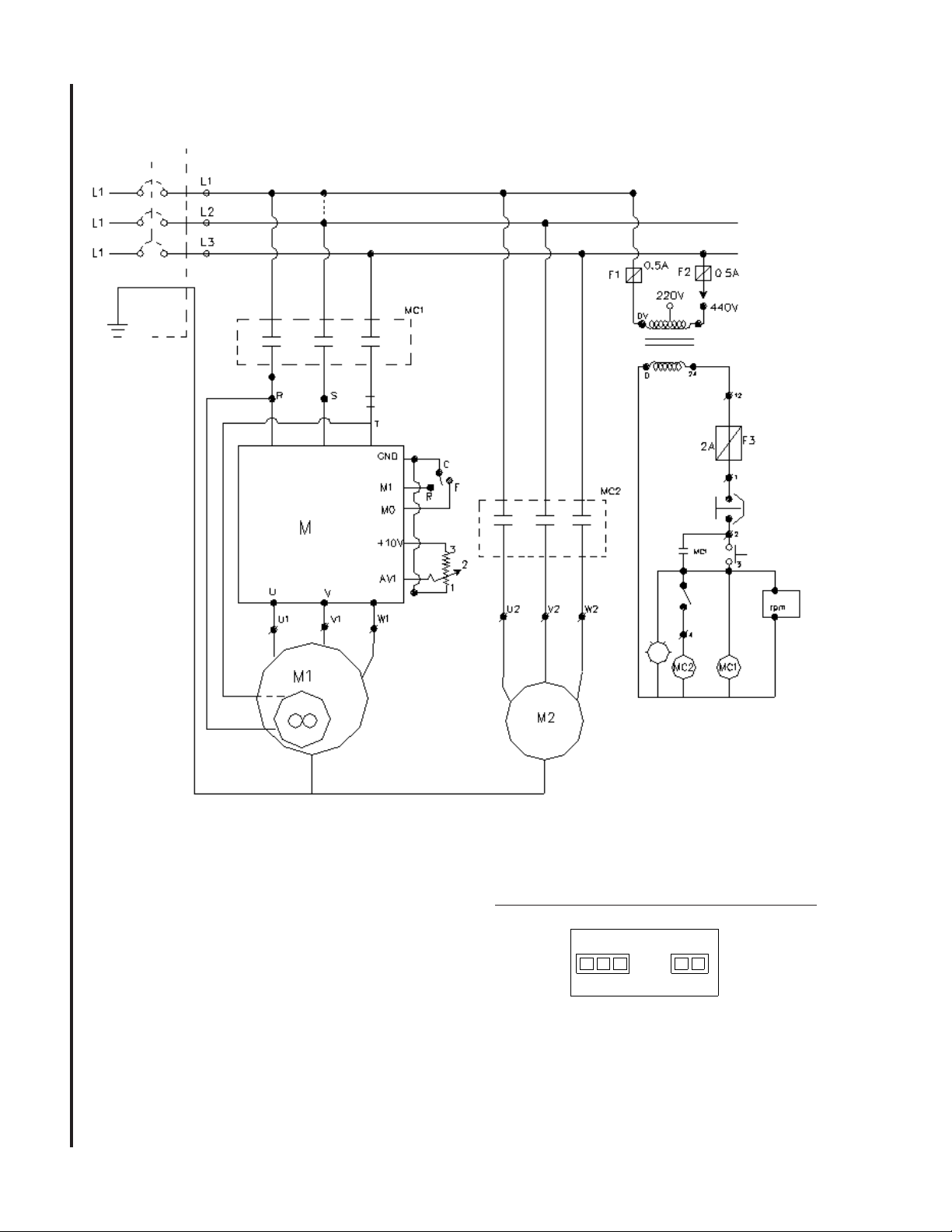
Page 13

Wiring Diagram - Models 2221 & 2223
13
Page 14
Wiring Diagram - Models 2232AC & 2234AC
14
AC Power
0 220
Volts
Sensor
- +
Input
3 Phase 220/440
LED Display Connection
Page 15

Troubleshooting
Problem Possible Cause Remedy
Spindle does not turn. 1. Motor overload protector tripped. 1. Press motor overload reset button.
2. Circuit breaker tripped. 2. Reset circuit breaker.
3. Branch circuit breaker tripped or fuse blown. 3. Reset branch circuit breaker/replace
fuse.
4. Open wire in switch circuit. 4. Repair open circuit.
5. Defective switch. 5. Replace switch.
6. Broken drive belt. 6. Replace drive belt.
Spindle noisy. 1. Damaged spindle bearings. 1. Replace bearings.
2. Worn spline. 2. Replace spline.
Drill stalls. 1. Worn drive belt. 1. Check condition of belt. Replace
if glazed or slipping on pulleys.
2. Excessive feed rate for size of drill and 2. Reduce feed pressure or use cutting
material being drilled. No cutting fluid or fluid. Use correct cutting fluid.
improper cutting fluid.
Poorly drilled holes. 1. Drill dull. 1. Sharpen drill.
2. Lack of rigidity in hold-down method. 2. Check that all T-slot hold-downs are
tight and that table-lock and drill
head bolts are tight.
3. Speed too fast for material and drill size. 3.
4. Feed too fast for material and drill size. 4. Reduce feed rate.
5. No or improper cutting fluid or coolant 5. Use cutting fluid, or change to
being used. proper fluid or coolant for material
6. Improperly ground drill bit. 6. Check for proper angles and reliefs.
Check spindle speed recommendations.
Reduce speed if necessary.
being drilled.
Regrind to proper geometry.
Motor overheating 1. Electrical circuit fault. 1. Check current draw in circuit.
Make sure current draw is the
same as rating on motor plate.
2. Oversize drill. 2. Reduce drill size.
3. Excessive feed. 3. Reduce feed rate.
4. No cutting fluid, or wrong fluid. 4. Use correct cutting fluid for the
material and drill.
Table can not be 1. Lack of lubrication. 1. Lubricate.
raised.
No speed readout. 1. Speed pickup out of adjustment or failed. 1. Adjust gap between speed pickup
and post spindle pulley. If there is
no readout on the LED speed
indicator after adjusting the gap,
replace the speed pickup.
15
Page 16

Optional Equipment
Coolant System Installation
1. Remove the large reservoir cover plate from the
machine base. Tap 1/4-20 threads in the 4 pilot holes.
Install the cover plate back onto the machine base.
2. Insert the pump into the opening, utilize the
screws from the small round cover plate to fasten the
pump to the base.
3. Position the power switch and valve bracket on the
spindle casting. Mark mounting hole locations and
drill holes. (Refer to Figure 8).
Note: Mount components near the lower edge of the
spindle casting. Do not mount componets above the
line shown in Figure 9.
4. Install the power switch and valve bracket with the
provided fastener hardware.
5. Install the 3/8-inch hose barb to the coolant pump.
If needed apply a light coat of pipe sealant or Teflon
tape to the threads to prevent leakage.
6. Mount the flow valve to the bracket, connect the
supply hose to the pump and valve, use hose clamps
at the ends.
7. Install the flexible nozzle to the flow valve.
8. Install the 1/2-inch hose barb to the worktable,
seal threads if needed. Connect the return hose.
9. Connect the power cord to a suitable source and
ground (refer to General Electrical Cautions).
10. Fill the reservoir with appropriate machining
coolant.
16
Figure: 8 Suggested installation
Power switch - mounting
plate flush with bottom
edge of spindle casting.
Do not mount components
above this line.
Flow valve
mounting bracket.
Figure 9: Installation Detail
Page 17

Replacement Parts
This section provides exploded view illustrations that show the replacement parts for Wilton Model 2221VS,
2223VS, 2232AC, and 2234AC 20-Inch Drill Presses. Also provided are parts listings that provide part number,
description, and quantity. The item numbers shown on the illustration relate to the item number in the facing
page of the parts listing.
Separate exploded views and parts listings are provided for the drill heads for manual speed control drill presses
(Models 2221VS and 2223VS) and the inverter speed control drill presses (Models 2232AC and 2234AC). The
exploded view and parts listing for the drill press spindle components, and the table, base, and column apply to
all models.
Order replacement parts from:
WMH TOOL GROUP
2420 Vantage Drive
Elgin, IL 60124
Phone: 800-274-6848
Identify the replacement part by the part number shown in the parts listing. Be sure to include the model
number and serial number of your machine when ordering replacement parts to assure that you will receive the
correct part.
17
Page 18

Exploded View — Drill Head — Manual Speed Control
(Models 2221VS and 2223VS)
18
Page 19

Parts Listing — Drill Head — Manual Speed Control
(Models 2221VS and 2223VS)
Item Part
No. Number Description Qty
7 5510077 Pulley, Spindle Step 1
8 5510078 Nut, Spindle 1
9 5510079 V-Belt 1
10 5510080 Pulley, Spindle, VS, Lower 1
11 5510081 Pulley, Spindle, VS, Upper 1
11A 5513673 Screw, Cap 1
11B 5513674 Nut, Hex 4
12 5510082 Bearing, Ball 1
13 5510083 Cover, Bearing 1
14 5510084 Lever, Speed Change 1
15 5510085 Bearing, Ball 2
16 5510086 Bushing 1
17 5510087 Bushing 1
18 5510088 Bolt, Hex 4
19 5510089 Washer 4
20 5510090 Housing, Bearing 1
21 5510091 Screw, Set 1
22 5510092 Shaft, Spindle Mid 1
23 5510093 Key 1
24 5510094 Key 1
25 5510095 C-Ring (Shaft) 1
26 5510096 Belt, Variable Speed 1
27 5510097 C-Ring (Shaft) 2
28 5510098 Cover, Spring 1
29 5510099 Spring
30 5510100 Pulley, Motor, VS, Lower 1
32 5510102 Key 1
33 5510103 Pulley, Motor, VS, Upper 1
34 5510104 Screw, Set 1
35 5510105 Bracket, Speed Change 1
36 5510106 Link 1
37 5510107 Shaft 1
38 5510108 C-Ring (Shaft) 1
39 5510109 C-Ring (Hole) 1
40 5510110 Bearing, Ball 2
41 5510111 Nut 2
42 5512114 Sleeve, Control Rod 1
43 5512115 Rod, Control 1
44 5510114 Pin Spring 1
45 5510115 Pin 1
46 5510116 Roller 1
47 5510117 Nut, Hex 1
48 5512116 Housing 1
49 5513675 Screw, Cap (M8x35) 2
50 5513676 Screw, Pan Head 6
51 5510121 Gear, Helix 1
52 5510122 Gear, Worm 1
53 5510123 Bearing, Thrust 1
54 5510124 Bushing 1
55 5513677 Set Screw 1
56 5510126 Wheel, Hand (includes #58) 1
57 5510127 Ring, Retaining 1
Item Part
No. Number Description Qty
58 5510126 Grip, Hand 1
59 5510129 Screw, Set 1
60 5513678 Assy., Pulley Cover (incl 1
60A,60B,60C,60D)
60A 5513679 Bracket, Nameplate 1
60B 5513680 Plate, Cover 1
60C 5513681 Screw, Cap 2
60D 5513682 Bracket, Plate 1
61 5510131 Bearing, Thrust 1
62 5510132 Shaft 1
63A 5513683 Screw, Cap 2
64A LED Display
5513519 115/230 LED Display
5513736 220/440 LED Display
65 5513690 Plate, Face 1
66 5513685 C-Ring (Hole) 1
67 5510137 Screw, Round Head 4
76 5511848 Knob 1
77 5514634 Set Screw (M3x8) 1
78 5511849 Cover 1
79 5513354 Screw 2
80 5510344 Motor 2hp 1ph 115/220V 1
5510345 Motor 2hp 3ph 220/440V 1
80A 5517320 Key, Square 1
80B 5517321 Washer, Flat 4
80C 5517322 Nut, Hex 4
81 Switch, Fwd/Rev 1
5517323 1 Phase
5517331 3 Phase
81A 5517324 Plate, Switch 1
81B 5517325 Label 1
81C 5517326 Cover, Label 1
82 5513356 Box, Switch 1
83 5513357 Screw 2
84 5513358 Nut, Hex 4
85 5513359 Screw 4
86A 5517327 Strain Relief 2
86B 5517328 Nut, Hex 2
87 5517329 Cord, Connection 1
88 5517330 Cord, Power 1
89 5513935 Assy., VS Spindle Pulley 1
90 5513934 Assy., VS Motor Pulley 1
91 Assy., Switch (includes 1
items 76-79,81-85)
5513355 1 Phase
5514716 3 Phase
19
Page 20

Exploded View — Drill Head — Inverter Speed Control
(Models 2232AC and 2234AC)
20
Page 21

Parts Listing — Drill Head — Inverter Speed Control
(Models 2232AC and 2234AC)
Item Part
No. Number Description Qty
1 5517332 Casting, Head 1
2 5510142 Window, Oil 1
3 5510143 Bearing, Ball 1
4 5510144 Ring, Retaining 1
5 5510145 Gear (32T) 1
6 5510146 Key 1
7 5510147 Shaft, Drive (13T) 1
8 5510148 Bearing, Ball 1
9 5510149 Ring, Retaining 1
10 5510150 Bearing, Ball 1
11 5510151 Ring, Retaining 1
12 5510153 Gear (55T) 1
13 5510152 Screw, Set 1
14 5510155 Spring 1
15 5510154 Ball, Steel 1
16 5510159 Key 1
17 5517333 Plug, Drain, 3/8 NPT 1
18 5510158 Gear (18T) 1
20 5510160 Key 1
21 5510161 Shaft, Mid 1
22 5510162 Key 1
23 5510163 Ring, Retaining 2
24 5510164 Bearing, Ball 1
25 5510165 Pin 1
26 5510166 Bar 1
26-1 5517334 Ring 1
27 5510167 Nut, Hex 1
28 5510168 Washer, Spring 1
29 5510169 Block, Speed Change 1
30 5510170 Bar, Gear 1
31 5510171 Screw, Set 1
32 5517335 Lever, Speed 1
33 5517336 Ring, Retaining 1
34 5510173 Seal, Oil 1
35 5510177 Shaft, Gear (18T) 1
36 5517337 Nut, Hex 1
37 5517338 Screw, Cap 1
38 5510178 Screw, Set 1
39 5517339 Cover (Top), Gearbox 1
40 5510180 Fitting, Fill, Oil 1
40-1 5517340 Tube, Fill 1
41 5510181 Seal, Oil 1
42 5510182 Bolt 1
43 5510183 Seal, Oil 1
44 5510184 Seal, Oil 1
44-1 5517341 Ring, Retaining 1
45 5510185 Screw, Set 1
46 5510186 Pulley, Drive 1
47 5517342 Pulley, Spindle, 48T 1
48 5517343 Belt, 720x8 1
49 5510189 Bolt, Hex, M6x30 2
49-1 5517344 Screw, Flat Head, M5x10 2
50 5517345 Washer, Flat, M6 2
51 5517346 Bracket 1
Item Part
No. Number Description Qty
51-1 5517347 Housing, Bearing 1
51-2 5517348 Bearing, Ball, 6002ZZ 1
52 5510192 Key 1
53 Motor, 2hp, 3ph 1
5517349 220V
5517350 440V
54 5510194 Washer 4
55 5510195 Screw 4
56 5510204 Switch, E-stop 1
56-1 5510197 Proximity Switch, Speed 1
56-2 5510198 Bracket, Proximity Switch 1
57 5510201 Light, Indicator 1
59 5510199 Switch, Pump Selector 1
60 5510200 Switch, Forward/Reverse 1
61 5510196 Potentiometer, Speed Control 1
62 5510202 Switch, Pushbutton, Green 1
63 5510206 Screw 4
64 5517351 Panel, Control 1
64-1 5517352 Bracket, Plate 1
65 5510209 Screw, Pan Head 2
66 5510210 Cover, Oil Filler 1
67 5517353 Cover, Pulley 1
67-1 5517354 Plate, Top 1
67-2 5510213 Plate, Fixed 1
67-3 5517355 Plate, Fixed 1
67-4 5510215 Screw, Pan Head 2
67-5 5517356 Screw 2
67-6 5517357 Screw 2
67-7 5517358 Washer 6
67-8 5510214 Screw, Pan Head 4
68 5510216 Washer, Spring 2
69 5510217 Screw 2
70 5517359 Enclosure (w/door & latch) 1
71 5510219 Screw 4
72 5510220 Bolt 4
73 5517360 Washer 4
74 5510222 Relief, Cable 1
74-1 5517361 Relief, Cable 1
75 5510223 Cable, Electric 1
75-1 5517362 Cable, Electric 1
76 5510224 Cover, Window 1
77 5517363 Panel, Component Mounting 1
79 5510227 Board, Insulation 1
80 5510228 Fuse Block 1
81 5510229 Transformer 1
82 5517364 Washer 4
83 5517365 Screw, Pan Head 4
84 5517366 Screw, Cap 4
84-1 5517367 Washer, Lock 4
84-2 5517368 Nut, Hex 4
85 Inverter, Delta, M-type 1
5510233 220V, 3ph
5512670 440V, 3ph
21
Page 22

Parts Listing — Drill Head — Inverter Speed Control
(Models 2232AC and 2234AC)
Item Part
No. Number Description Qty
85-1 5517371 Washer, Flat 4
85-2 5517372 Screw 4
86 5517373 Sub-Panel 1
86-1 5517374 Screw 4
87 5510235 Terminal Block 1
88 5517375 Rail, Mounting 1
89 5510237 Contactor 1
89-1 5510238 Relay 1
90 5510240 Relay 1
94 5510242 Screw 2
95 5510243 Screw 2
96 5510244 Microswitch 2
97 5510245 Bracket, Microswitch 2
98 5510246 Rod, Microswitch Support 1
99 Electrical Enclosure Complete 1
5514648 220V, 3Ph
5514649 440V 3Ph
105 LED Display 1
5513519 115/220 LED Display
5513736 220/440 LED Display
106 5513683 Screw, Cap 2
107 5515285 Cap, Spindle 1
22
Page 23

Exploded View — Spindle Components (All Models)
23
Page 24

Parts Listing — Spindle Components (All Models)
24
Item Part
No. Number Description Qty
1 5517332 Casting, Head 1
2 5517376 Bolt, Hex, Shoulder 2
2-1 5517377 Spring 2
3 5517378 Rod, Cam Lock 2
4 5510250 Nut, Hex 2
5 5510251 Wrench, Hex Head 1
7 5510252 Screw, Set 1
8 5517379 Washer, External Tooth 1
10 5510253 Spindle 1
11 5510254 Bearing, Ball 2
12 5510255 Spacer 1
14 5510256 C-Ring 1
15 5510258 Screw, Set 1
16 5510259 Pin, Roll 1
26 5510261 Screw, Socket Head 1
27 5510262 Washer 1
28 5510263 Container, (includes #29) 1
29 5510263 Spring, Return 1
30 5510265 Screw, Socket Head 3
31 5510266 Seat, Spring 1
32 5510267 Pin, Spring 1
36 5513770 Washer, Rubber 1
37 5513771 Band, Quill 1
37A 5517380 Bolt, Hex, Shoulder 1
37B 5517381 Washer, Flat 2
37C 5517382 Nut, Hex 1
38 5513772 Nut, Lock 2
39 5513773 Bearing, Ball 1
40 5513774 Pin, Drift 1
41 5510268 Quill 1
42 5510269 Bearing, Ball 1
43 5510270 Spindle 1
44 5510271 Seal, Oil 1
45 5510272 Nut 1
46 5510273 Rod, Depth 1
48 5510274 Nut 1
49 5510275 Nut 1
50 5510276 Retainer 1
51 5510277 Pin, Spring 1
53 5510278 Scale, Depth 1
58 5510279 Screw, Round Head Cap 4
60 5510280 Key 1
61 5510281 Screw, Socket Head 3
62 5510282 Key 1
63 5510283 Shaft, Feed 1
66 5510284 Seat, Feed Shaft 1
Item Part
No. Number Description Qty
67 5510285 Hub 1
68 5510286 Spoke 3
68A 5513515 Pickup, Magnetic 1
68B 5513687 Screw, Pan Head 2
69 5510287 Knob 3
69A 5517383 Plate, Adjustable 1
69B 5517384 Bracket, Mag. Pickup 1
69C 5513689 Screw, Cap 1
69D 5517385 Washer, Flat 1
69E 5517386 Nut, Hex 1
70 5517387 Screw 2
71 5511849 Cover 1
72 5513354 Screw 4
Page 25

Exploded View - Table and Base (All Models)
25
Page 26

Parts List - Table and Base (All Models)
26
Item Part
No. Number Description Qty
1 5510288 Base 1
2 5510289 Plate, Coolant Cover 1
3 5510456 Pump, Coolant, 115V, 1P 1
5512103 Pump, Coolant, 220/440V 3P 1
4 5510291 Bolt, Hex 4
5 5517388 Screw, Pan Head 3
6 5510293 Seat, Ball 1
7 5510294 Screw, Set 4
7-1 5517389 Block, Brass 4
8 5510295 Bearing, Ball 1
9 5510296 Ring, Lock 1
9-1 5517390 Pin 1
10 5516859 Shaft, Table Raiser 1
11 5510298 Pin, Spring 4
12 5516858 Shaft, Table Clamp 1
13 5516860 Coupling, Table Raiser 1
14 5510300 Screw, Socket Head 1
15 5510301 Nut 1
16 5510302 Rack 1
17 5514663 Gear, Bevel, Large 1
18 5517391 Housing, Bearing 1
18-1 5517392 Bearing, Ball, 6202ZZ 2
18-2 5517393 Washer 2
18-3 5510303 Screw, Cap 2
19 5510304 Gear, Bevel, Small 2
20 5510305 Bracket Cover 1
21 5510306 C-Ring 1
22 5510307 Bearing, Ball 1
23 5510308 Shaft 1
24 5510309 C-Ring 2
25 5510310 Screw, Socket Head 4
26 5510311 Shaft 1
27 5517395 Screw, Set 1
28 5510313 Key 1
29 5510314 Bearing 1
30 5510315 Worm, Table Raise 1
31 5510316 Key 1
32 5510317 Gear, Worm 1
33 5510318 Gear 1
34 5510319 Lock, Cam, Front 1
35 5510320 Lock, Cam, Rear 1
35-1 5517396 Spring 1
35-2 5517397 Screw, Cap, M6x25 1
35-3 5517398 Pin, 5x25 2
36 5510321 Crank, Table Raise 2
37 5510322 Table 1
37-1 5517399 Barb, Hose, 1/2" (return) 1
38 5510323 Column 1
39 5510324 Handle, Table Raise 1
40 5510325 Screw, Hex Head 1
40-1 5510334 Washer 1
Item Part
No. Number Description Qty
41 5510326 Clamp 1
42 5510327 Screw, Pan Head 1
43 5510328 Hose, Vinyl, Clear, 3/8" 1
44 5510329 Barb, Hose, 3/8" (supply) 1
45 5512112 SHCS, #10-32 x 1" 4
46 5510331 Bracket, Mounting 1
47 5510332 Valve 1
48 5510333 Nozzle, Flexible 1
49 5517400 Screw, Pan Head 1
50 5517401 Hose, Vinyl, Clear, 1/2" 1
51 5517402 Clamp, Hose 1
52 5517403 Screw, Set, 1/2 x 1 2
53 5517404 Plug, Drain, 3/8 NPT 1
54 5517405 Pin, Spring, 4x50 1
55 5517406 Collar, Rack 1
56 5513932 Assembly, Table Raiser 1
57 9057451 Washer, Flat, #10 2
58 5517488 Nut, Hex, 1/2" 1
59 5517489 Cord, Power 1
60 5517490 Assy., Switch 1
61 Cord, Pump 1
5517491 1 Phase
5517492 3 Phase
62 5517493 Clamp, Hose, Rad. Type 2
63 9058341 Washer, Lock, #10 4
64 5517628 Nut, Hex, #10-32 4
65 Coolant System Complete 1
5512104 1/8 HP, 115/220V, 1 Phase
5508071 1/8 HP, 220/440V, 3 Phase
Page 27

Page 28

WMH TOOL GROUP
2420 Vantage Drive
Elgin, IL 60123
Phone: 800-274-6848
 Loading...