

Page 1
Pioneering for You
Wilo-Sevio AIR
de Einbau- und Betriebsanleitung
US Installation and operating instructions
hu Beépítési és üzemeltetési utasítás
6068088 Ed.0.5-11/2012 no ofcial version
Page 2
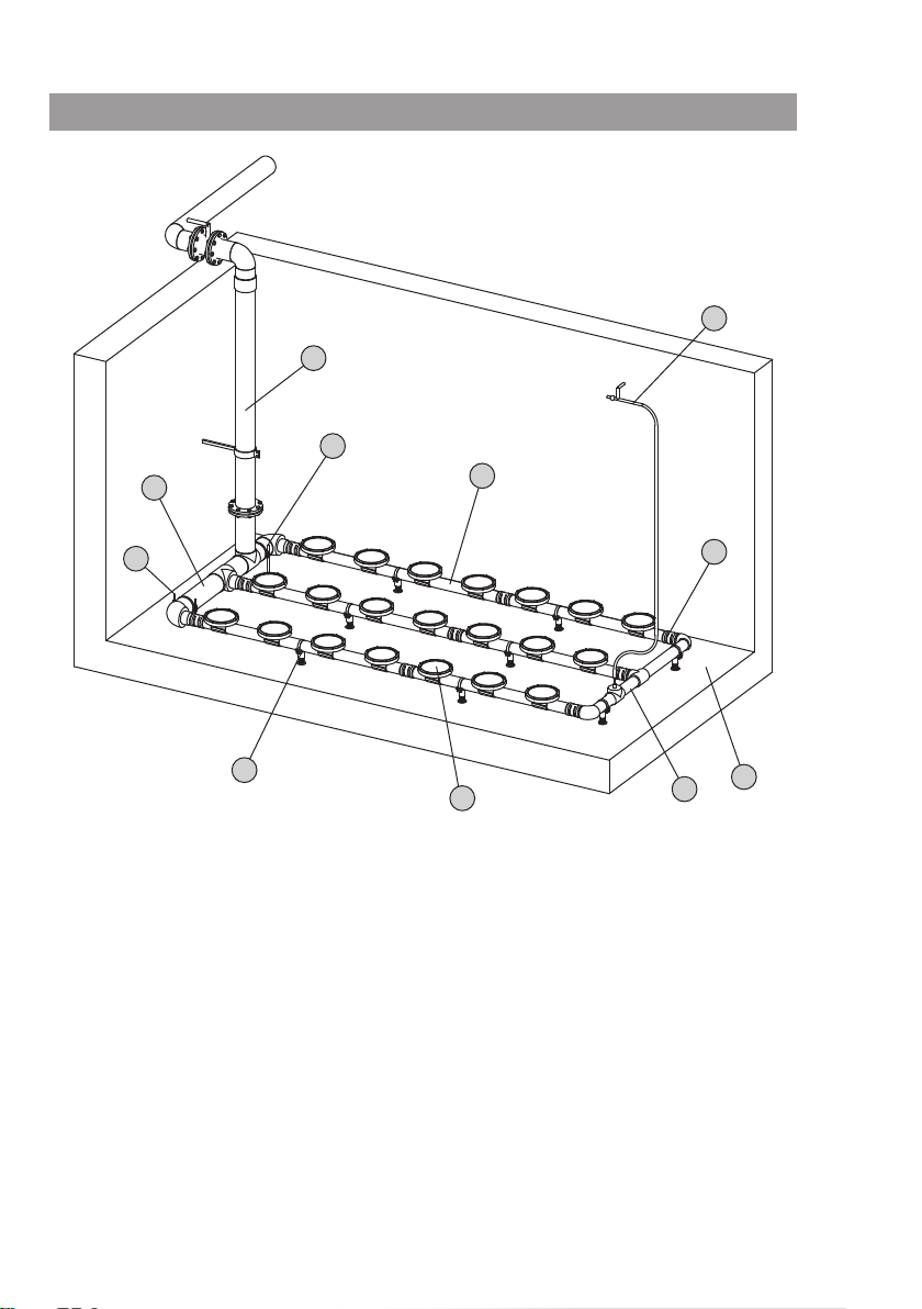
Fig. 1
10
3
2
1
4
2
5
6
8
7
9
Page 3
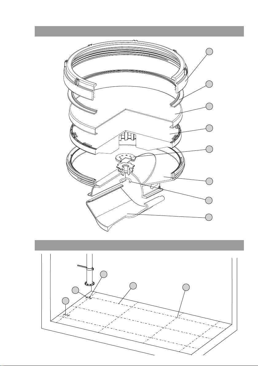
Fig. 2
1
2
3
4
5
6
7
Fig. 3
8
1
2
3
4
2
Page 4
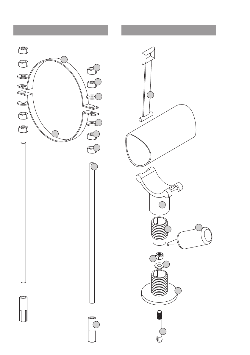
Fig. 5Fig. 4
6
8
7
5
7
5
6
4
3
2
6
5
8
4
3
2
1
1
Page 5
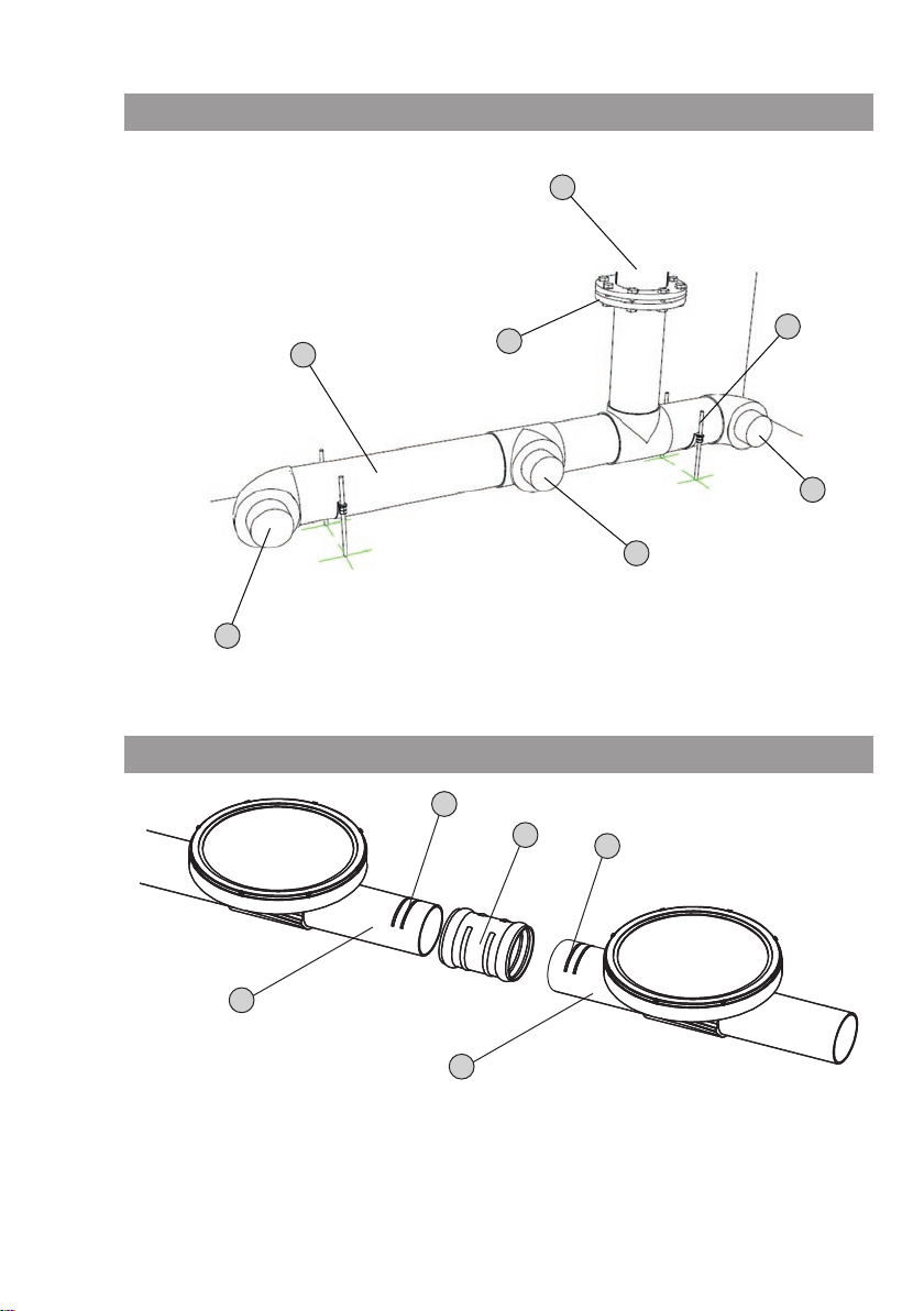
Fig. 6
2
Fig. 7
1
4
3
5
5
5
3
1
3
2
2
Page 6
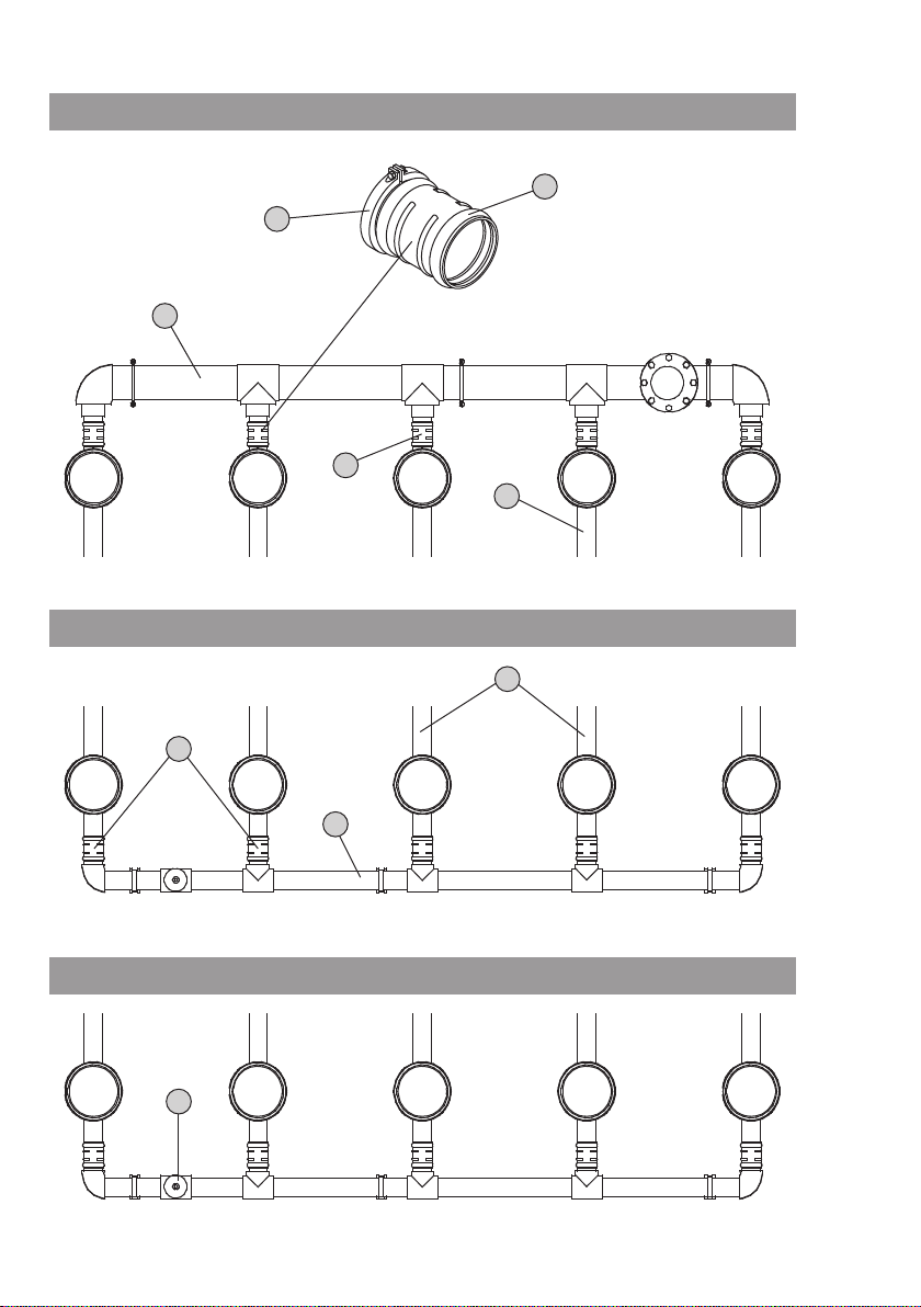
Fig. 8
Fig. 9
4
5
2
1
3
1
Fig. 10
3
2
1
Page 7
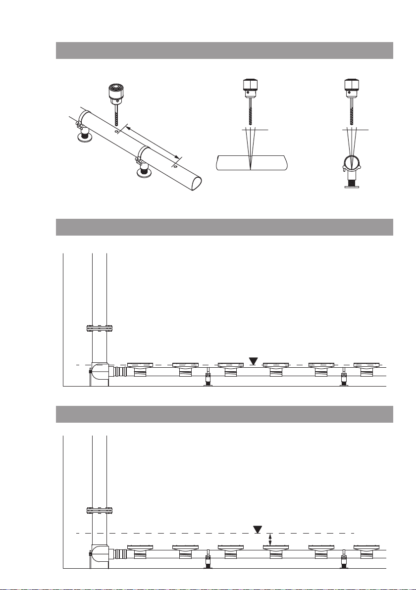
Fig. 11
Fig. 12.1
min. 800 mm
±5° ±1°
Fig. 12.2
10 cm
Page 8
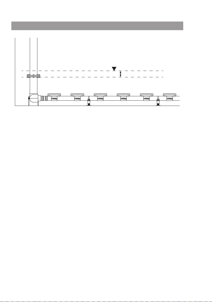
Fig. 12.3
10 cm
Page 9

English
1. Introduction 44
1.1. About this document 44
1.2. Structure of the manual 44
1.3. Personnel qualications 44
1.4. Abbreviations 44
1.5. Illustrations 45
1.6. Copyright 45
1.7. Rights of alteration 45
1.8. Warranty 45
2. Safety 46
2.1. Instructions and safety information
47
2.2. General safety information 48
2.3. CE marking 49
2.4. Ground connection 49
2.5. Safety rules during operation 49
2.6. Liquids 49
2.7. Sound pressure 50
3. Transport and storage 50
3.1. Delivery 50
3.2. Transport 50
3.3. Storage 50
6. Start-up 63
6.1. Initial start-up 63
6.2. Before switching on 65
6.3. Starting up the aeration 65
6.4. After switching on 65
7. Shutdown/disposal 66
7.1. Temporary shutdown 66
7.2. Shutdown for maintenance work or
storage 66
7.3. Starting up again 67
7.4. Disposal 67
8. Maintenance 68
8.1. Maintenance intervals 69
8.2. Maintenance tasks 70
8.3. Repairs 71
4. Product description 51
4.1. Proper use 51
4.2. Construction 51
4.3. Function 53
4.4. Technical data 53
4.5. Scope of delivery 53
5. Installation 54
5.1. General requirements 54
5.2. Types of installation 55
5.3. The operating area 55
5.4. Work steps 56
Installation and operating instructions Wilo-Sevio AIR 43
Page 10

English INTRODUCTION
1. Introduction
1.1. About this document
The language of the original operating manual is German. All other language versions
are translations of the original German manual.
The operating manual contains a copy of the EC Declaration of Conformity.
Any unauthorized or unapproved changes made to the design specied in it will nullify
this declaration.
1.2. Structure of the manual
The manual is divided into individual sections. Each section has a heading which clearly
describes its content.
The table of contents also serves as a brief reference, since all the important sections
have their own headers.
All the important operating and safety instructions are highlighted. For detailed information on the structure of these texts, see “Safety” in section 2.
1.3. Personnel qualications
All personnel who work on or with the product must be qualied for such work; electrical work, for example, may only be carried out by a qualied electrician. All personnel
must be of legal age.
Operating and maintenance personnel must also observe national accident prevention
regulations.
It must be ensured that the personnel have read and understood the instructions in this
operating and maintenance handbook; if necessary, this manual must be ordered from
the manufacturer in the required language.
This product is not intended to be used by persons (including children) with limited
physical, sensory or mental capacities or without the relevant experience or knowledge,
unless they are supervised by a person responsible for their safety and receive instructions from this person on how to use the product.
Children must be supervised in order to ensure that they do not play with the product.
1.4. Abbreviations
• p.t.o. = please turn over
• re. = regarding
• approx. = approximately
• i.e. = that means
• incl. = including
• min. = minimum
• max. = maximum
• etc. = and so on
• s.a. = see also
• e.g. = for example
44 WILO SE 11/2012 Ed.03 DIN A5
Page 11

INTRODUCTION English
1.5. Illustrations
Dummies and original drawings of the products are used in the illustrations. This is the
only sensible solution given our wide range of products and the differing sizes offered
by the modular system. More exact drawings and specications can be found on the
dimension sheet, the planning information and the installation plan.
1.6. Copyright
This operation and maintenance manual has been copyrighted by the manufacturer.
The operation and maintenance handbook is intended for use by assembly, operating
and maintenance personnel. It contains technical specications and diagrams which
may not be reproduced or distributed, either completely or in part, or used for any other
purpose without the express consent of the manufacturer.
1.7. Rights of alteration
The manufacturer reserves the right to make technical alterations to systems or components. This operating and maintenance manual refers to the product indicated on the
title page.
1.8. Warranty
This section contains the general information on the warranty. Contractual agreements
have the highest priority and are not superseded by the information in this section.
The manufacturer is obliged to correct any defects found in the products it sells, provided that the following requirements have been fullled:
1.8.1. General requirements
• The defects are caused by the materials used or the way the product was manufactured
or designed.
• The defects were reported in writing to the manufacturer within the agreed warranty
period.
• The product was used only as prescribed.
• All safety and control devices were connected and inspected by qualied personnel.
1.8.2. Warranty period
If no other provisions have been made, the warranty period covers the rst 12 months
after initial start-up or up to 18 months after the delivery date. Other agreements must
be made in writing in the order conrmation. These remain valid at least until the agreed
warranty period of the product has expired.
1.8.3. Spare parts, add-ons and modications
Only genuine spare parts from the manufacturer may be used for repairs, replacements,
add-ons and modications. These are the only parts that guarantee a long service life
and maximum safety. These parts have been specially designed for our products. Unau-
Installation and operating instructions Wilo-Sevio AIR 45
Page 12

English SAFETY
thorized add-ons and modications or the use of non-original spare parts can seriously
damage the product and injure personnel.
1.8.4. Maintenance
The prescribed maintenance and inspection work should be carried out regularly. This
work may only be carried out by qualied, trained and authorized personnel. Maintenance not listed in this operation and maintenance manual, and any type of repair work
may only be performed by the manufacturer and authorized service centers.
1.8.5. Damage to the product
Damage and malfunctions that endanger safety must be eliminated immediately by
trained personnel. The product may only be operated if it is in proper working order.
During the agreed warranty period, the product may only be repaired by the manufacturer or an authorized service center. The manufacturer reserves the right to ask the
operator to return the damaged product to the factory for inspection.
1.8.6. Exclusion from liability
No liability will be assumed for product damage if any of the following items apply:
• The manufacturer deems that information provided by the operator or customer is
insufcient or incorrect
• Failure to observe the safety instructions, the regulations and requirements of German
law or the applicable local laws, or of this operating and maintenance manual
• Improper use
• Incorrect storage and transport
• Improper assembly or dismantling
• Insufcient maintenance
• Improper repairs
• Inadequate construction site or construction work
• Chemical, electrochemical and electrical inuences
• Wear
This means the manufacturer’s liability excludes all liability for personal, material or
nancial injury.
2. Safety
This section lists all the generally applicable safety instructions and technical information.
All instructions and information must be observed and followed during the various
phases of the product’s life cycle (installation, operation, maintenance, transport, etc.)!
The operator is responsible for ensuring that personnel follow these instructions and
guidelines.
46 WILO SE 11/2012 Ed.03 DIN A5
Page 13

SAFETY English
2.1. Instructions and safety information
This manual uses instructions and safety information to prevent injury and damage to
property. To clearly identify them for personnel, the instructions and safety information
are distinguished as follows:
2.1.1. Instructions
Instructions are displayed in bold type. Instructions contain text that refers to the previous text or particular sections, or highlights short instructions.
Example:
Note that products stored with drinking water must be protected from frost.
2.1.2. Safety information
Safety information is slightly indented and displayed in bold type. It always commences
with a signal word.
Information that only refers to material damage is printed in gray, without safety symbols.
Information that refers to personal injury is printed in black and is always accompanied by a safety symbol. Danger, prohibition or instruction symbols are used as safety
symbols.
Example:
DANGER symbol: General hazard
DANGER symbol, for example, electrical current
PROHIBITION symbol, for example, Keep out!
INSTRUCTION symbol, for example, wear protective equipment
The safety symbols used conform to the generally valid directives and regulations, such
as DIN and ANSI.
Each safety instruction begins with one of the following signal words:
• Danger
Serious or fatal injuries can occur!
Installation and operating instructions Wilo-Sevio AIR 47
Page 14

English SAFETY
• Warning
Serious injuries can occur!
• Caution
Injuries can occur!
• Caution (instruction without symbol)
Substantial material damage can occur. Irreparable damage is possible!
Safety instructions begin with a signal word and description of the hazard, followed by
its cause and potential consequences, and end with advice on prevention.
Example:
Beware of rotating parts!
The moving impeller can crush and sever limbs. Switch off the device and let the
impeller come to a halt.
2.2. General safety information
• When installing or removing the product, never work alone in rooms and shafts. A second person must always be present.
• Sufcient ventilation must be provided in enclosed rooms.
• When welding or working with electrical devices, make sure there is no risk of explosion.
• During work in environments hazardous to health (liquid containing fecal matter, acti-
vated sludge with bacteria, etc.), special caution is required:
• Open wounds must be immediately cleaned and treated.
• Eating and drinking are strictly prohibited.
• Proper protective equipment must be worn!
• Upon leaving the system, disinfect persons and tools.
• The product must always be switched off before any work is performed on it (assembly,
dismantling, maintenance, installation). The product must be secured against being
switched back on.
• The person operating the product must notify his or her supervisor immediately should
any defects or irregularities occur.
• Tools and other objects should be kept in a place reserved for them so that they can be
found quickly.
• Only use lashing equipment which is legally dened as such and ofcially approved.
• The lashing equipment must be kept safely and must be suitable for the conditions of
use (weather, hooking device, load, etc).
• Mobile equipment for lifting loads should be used in such a way that it always remains
stable during operation.
• When using mobile equipment for lifting non-guided loads, take action to prevent
tipping, sliding, etc.
• Measures should be taken to ensure that no person is ever directly beneath a suspended
load. Furthermore, it is also prohibited to move suspended loads over workplaces where
people are present.
48 WILO SE 11/2012 Ed.03 DIN A5
Page 15

SAFETY English
• If mobile equipment is used for lifting loads, a second person should be present to coordinate the procedure if required (for example, if the operator’s eld of vision is blocked).
• The load to be lifted must be transported in such a manner that nobody can be injured
in the event of a power outage. Additionally, when working outdoors, such procedures
must be stopped immediately if weather conditions worsen.
These instructions must be strictly observed. Non-observance can result in injury or
substantial material damage.
2.3. CE marking
If the product is obliged to carry a CE marking,
• the marking is attached to the product and
• a copy of the EC declaration of conformity is enclosed or is part of this operating man-
ual.
2.4. Ground connection
Products with metallic and/or conductive surfaces must be grounded. If there is a possibility that people can come into contact with the product and the pumped liquid, the
connection must be additionally equipped with a residual current circuit breaker.
2.5. Safety rules during operation
When operating the product, always follow the locally applicable laws and regulations
for accident prevention and securing the worksite. To help to ensure safe working
practice, the responsibilities of employees should be clearly set out by the owner. All
personnel are responsible for ensuring that regulations are observed.
2.6. Liquids
Each liquid differs in terms of its composition, corrosiveness, abrasiveness and dry matter content, as well as in many other aspects. Generally, our products can be used for
many applications. Please note that if requirements change (density, viscosity or general
composition), this can also affect many operational parameters of the product.
When using or replacing the product in a different liquid, observe the following points:
• When used in drinking water applications, all the parts that come into contact with the
uid must be approved for use with drinking water.
Before being used in drinking water, the corresponding products must be checked to
ensure that they have been approved for such use.
• Products that have been operated in dirty waste water must be cleaned thoroughly
before being used for other liquids.
• Products that have been operated in sewage water and/or uids that are hazardous to
health must be decontaminated before being used with other liquids.
It must be claried whether the product can be used with another liquid.
Installation and operating instructions Wilo-Sevio AIR 49
Page 16

English TRANSPORT AND STORAGE
• If the product is to be used with highly ammable, explosive and/or aggressive uids,
the manufacturer must be consulted.
2.7. Sound pressure
The product itself is generally operated under water and only with air. This means that
the sound pressure cannot be measured.
However, the air is supplied using a compressor. Depending on its power and environmental conditions, this compressor can have elevated sound pressure.
For this reason we recommend that the operator carry out an the additional measurement in the workplace when the product is operating.
CAUTION: Wear ear protectors!
In terms of the applicable laws and regulations, ear protection must be worn if the
sound pressure is greater than 85 dB (A). The owner is responsible for ensuring
compliance with these regulations.
3. Transport and storage
3.1. Delivery
On delivery, immediately check that the product is complete and undamaged. If any
parts are damaged or missing, the transport company or the manufacturer must be notied on the day of delivery. Claims made after this date cannot be recognized. Damage
to parts must be noted on the delivery or freight documentation.
3.2. Transport
Before transport, the product must be packaged in such a way that it is protected from
moisture, frost and other damage. It is important to keep the original packaging.
3.3. Storage
• The components must be stored in the original packaging.
• The store room must be dry and frost-proof. We recommend storage in a room with a
temperature between 10°C and 25°C. The temperature may not exceed +50°C.
• The product must be protected from direct sunlight, heat, dust and frost. Furthermore,
the product may not be stored in rooms where welding takes place. Heat and cold, as
well as the gas and radiation given off during welding, can damage the plastic parts.
• New disc aerators may not be stored for more than three months. If they are stored for
more than three months, there is a risk that the membranes will become porous and
leaky.
50 WILO SE 11/2012 Ed.03 DIN A5
Page 17

PRODUCT DESCRIPTION English
4. Product description
4.1. Proper use
The Wilo-Sevio AIR disc aerator and aerator systems are used for ne-bubble air
inclusion in liquids such as water, waste water or sludges, for the purpose of supplying
oxygen to the liquids.
The temperature of the liquid must be between +5°C and 30°C. If the products are to
be used in liquid with higher temperatures, the manufacturer must be consulted. The
surrounding liquid must also be free of objects with sharp edges. We recommend that
the liquid be pre-cleaned with a lter.
The supplied air must be free of oil, dust and solvents. Dust lters must correspond to
lter class EU4 according to DIN24185 (degree of separation >90%).
All lters and insulating materials in use may not be made of berglass, mineral bers or
other materials consisting of ne bers. Rotary slide valves with graphite ns must be
equipped with an air lter on the pressure side.
These materials can lead to clogging of or damage to the membranes.
4.2. Construction
A Wilo-Sevio AIR aerator system consists of one or more aerator groups. An aerator
group forms the base unit and consists of several components:
Fig. 1.: Aerator system component overview
Air distributor with connecting ange for
1
the intake line (down pipe)
2 Base support for air distributor 7 Basin bottom
Intake line (down pipe); must be installed
3
by the customer.
Aerator pipe with pre-assembled disc
4
aerators
5 Base support for aerator pipe 10
6 Disc aerators
Pipe coupling for connecting the individ-
8
ual components
9 Drainage connection
Drainage line; must be installed by the
customer.
4.2.1. Piping
The pipes are pre-fabricated in components that can be easily used:
• PVC air distributors in the diameters of 90mm, 160mm and 200mm with central or
lateral DN80 to DN200 ange connection for the intake line. Larger diameters are
available in stainless steel with DN125 to DN350 ange connections.
• PVC aerator pipes with 90mm external diameter or made from stainless steel with
88.9mm external diameter with pre-assembled disc aerator
Installation and operating instructions Wilo-Sevio AIR 51
Page 18

English PRODUCT DESCRIPTION
• Drainage connection as the terminating connection of all aerator pipes with a connection for the drainage line. This can be used to drain off the condensate that can form
during aeration.
• Pipe coupling with rubber ring seal as a plug connection for connecting the individual
PVC components. The pipe coupling for securing the aerator pipes on the air distributor
must also be equipped with a stainless steel clamping ring.
4.2.2. Base support
All pipes on the basin bottom are secured by the base supports. They also make it possible to level the aerator group.
There are two different base supports:
• For securing the stainless steel air distributor
• For securing the aerator pipes and the PVC drainage connection
4.2.3. Disc aerators
The disc aerators introduce the supplied air into the liquid. The air is distributed across
the entire membrane surface and released through the perforated membrane. The disc
aerator consists of several components.
Fig. 2.: Disc aerator component overview
1 Threaded ring 5 Non-return valve
2 Separation ring 6 Aerator housing
3 Membrane 7 O ring
4 Membrane support 8 Slide closure
• Fiberglass-reinforced plastic threaded ring for securing the membrane to the membrane
support. The threaded ring and aerator housing are matched to each other in such a
way that the threaded ring can be easily loosened even after years of use, allowing the
membrane to be replaced.
• The polyacetal separation ring prevents the membrane from sticking to the threaded
ring. This ensures that the membrane can be easily replaced.
• The EPDM membrane with perforations across its entire surface for optimal air inclusion.
• Fiberglass-reinforced plastic membrane support, which holds the membrane in place.
• The EPDM non-return valve protects the aerator system from penetration of the liquid if
the membrane is defective.
• Fiberglass-reinforced plastic aerator housing with integrated anti-rotation lock
• NBR O ring for sealing the disc aerator against the aerator pipe
• Fiberglass-reinforced sliding closure for easy installation and removal of the disc aerator
52 WILO SE 11/2012 Ed.03 DIN A5
Page 19

PRODUCT DESCRIPTION English
4.3. Function
A blower or compressor is used to pump air through the intake line into the air distributor. The air is evenly distributed into the aerator pipes through the air distributor and
fed to the disc aerators. The disc aerators distribute the air across the entire membrane
surface and introduce this air into the liquid.
4.4. Technical data
• Disc aerators
• External diameter: 280mm
• Membrane diameter: 237mm
• Membrane surface: 0.044m²
• Oxygen utilization: 6.5 ... 8.5%/m
• Size of the air bubbles: 1–3mm
• Pressure loss: 22 ... 43mbar
• Connection size: 88.9 ... 90mm
• Max. air temperature in the system / disc aerator: 100°C
• Pressurization range
• Air volume range: 1–8Nm³/h*
• Min. pressurization: 1.5Nm³/h*
• Standard pressurization: 4.0Nm³/h*
• Max. pressurization: 6.0Nm³/h*
Pressurization of 7.5Nm³/h* is possible for a brief period (no more than 15 minutes).
*The values for the pressurization apply to standardized conditions: 0°C and 1013hPa.
4.5. Scope of delivery
The scope of delivery differs according to whether a complete aerator system or only
disc aerators (with the pipes provided by the customer) were ordered.
4.5.1. “Aerator system” scope of delivery
• Air distributor with ange connection for intake line
• Aerator pipes with pre-assembled disc aerator
• Drainage connection
• Pipe connections
• Base support
• Fastening material
• Drilling plan for the base supports
• Overview and position diagram of the individual components
• Special key for easy installation/removal of the threaded ring on the disc aerator
• Rubber mallet
4.5.2. “Disc aerator” scope of delivery
• Disc aerators
• Drilling plan for the connection holes on the pipes for the disc aerators
Installation and operating instructions Wilo-Sevio AIR 53
Page 20

English INSTALLATION
4.5.3. Material to be provided by the customer
• Intake line for the air supply
• Blower or compressor
• Drainage line with shut-off valve
• All pipes if only disc aerators were ordered
5. Installation
In order to prevent damage to the product or serious injury during installation, the
following points must be observed:
• Installation work – assembly and installation of the machine – may only be carried out
by qualied persons. The safety instructions must be followed at all times.
• The machine must be inspected for transport damage before carrying out any installation work.
5.1. General requirements
For planning and operation of technical waste water systems, pay attention to the pertinent local regulations and directives for wastewater technology (such as those of the
German Association for Water, Wastewater and Waste).
The following information must be observed when installing the product:
• This work must be carried out by qualied personnel.
• Check that the available planning documentation (installation plans, layout of the oper-
ating area, drilling plan) is complete and correct.
• Observe all regulations, rules and legal requirements for working with and underneath
heavy suspended loads.
• Wear appropriate protective equipment.
• During all work, a second person must always be present. If there is a risk of poisonous
or asphyxiating gases forming, the necessary precautions must be taken.
• Please also observe the applicable national accident prevention regulations and trade
association safety provisions.
DANGER of falling!
Work may be necessary directly at the edge of the shaft and/or basin during installation. Carelessness or wearing inappropriate clothing could result in a fall. There is
a risk of fatal injury! Take all necessary safety precautions to prevent this.
54 WILO SE 11/2012 Ed.03 DIN A5
Page 21

INSTALLATION English
BEWARE of poisonous substances!
During work in environments hazardous to health, such as waste water or sewage
treatment plants, there is an increased hazard from bacteria and viruses. In order to
counteract this elevated risk, please keep the following points in mind:
• Open wounds must be immediately cleaned and treated.
• Eating and drinking are strictly prohibited.
• Proper protective equipment must be worn.
• Upon leaving the system, disinfect persons and tools.
5.2. Types of installation
• Aerator group securely xed to the basin bottom
5.3. The operating area
• The operating area must be clean, with coarse solid particles removed, dry, frost-free
and, if necessary, decontaminated.
• During all work, a second person must be present for safety reasons.
• If there is a risk of poisonous or asphyxiating gases forming, the necessary precautions
must be taken.
• Safe, truck-accessible access must be available to the operating area.
• A storage location of sufcient size and with a solid subsurface must be available so
that the complete load can be unloaded and stored in accordance with the specications in the “Transport and storage” section.
• Provisioning of the electricity, water and compressed air supply for the installation.
• It must be ensured that hoisting gear can be tted without any trouble, since this is re-
quired for assembly and removal of the product. It must be possible to reach the product
safely in its operating and storage locations using the hoisting gear.
• For transport of the product, load-carrying equipment must be secured to the pipes
with approved fastening devices. Here it is necessary to ensure that the load does not
shift during transport.
• The structural components and foundations must be of sufcient stability in order to
allow the product to be anchored securely and functionally. The operator or the supplier
is responsible for the provision of the foundations and their suitability in terms of dimensions, stability and strength.
5.3.1. Material to be provided by the customer
• Intake line for the air supply
The aerator group is connected through the air distributor to the intake line. The position of the intake line may not change after the order is placed, since this can otherwise
lead to problems during installation.
The intake line also needs to be self-supporting. The weight of the intake line may not
be transferred to the air distributor.
We also recommend installation of a compensating joint between the intake pipe and
Installation and operating instructions Wilo-Sevio AIR 55
Page 22

English INSTALLATION
the rest of the pipelines, as well as installation of a manometer in the intake line. These
measures allow tension and transmissions of vibration to be reduced and the current air
inclusion to be checked.
• Blower or compressor
The blower or compressor must have sufcient output for introducing the required air
volume into the aerator group(s).
• Drainage line with shut-off valve
In order to channel off any liquid that has penetrated into the aeration system or condensate that has formed during operation.
• All pipes if only disc aerators were ordered
If only disc aerators were ordered, the complete pipe system must be installed in advance.
5.4. Work steps
Installation takes place in the following steps:
1. Checking the operating area
2. Unpacking and checking the components
3. Installing the base supports
4. Aligning the contact surface for the pipes
5. Installing the air distributor
6. Installing the aerator pipes
7. Installing the drainage connection
8. Securing the pipes
9. Installing the drainage line
10. Installing the disc aerators
When a complete aerator system is being installed, the disc aerators are already pre-assembled. In this case, item 10 is omitted during installation. If the pipe system is being
provided by the customer and only disc aerators were ordered, items 3 to 9 are omitted
during installation.
5.4.1. Checking the operating area
Before you begin with installation, check the operating area to ensure that it is prepared
for installation:
• The design of the system as well as the installation and drilling plan match the current
conditions.
• The operating area is clean and the components to be provided by the customer are
appropriately prepared/installed.
• PVC becomes brittle when subjected to cold temperatures. For this reason, the ambient
temperature must be over +10°C during installation.
Installation with an ambient temperature below +5°C is strictly prohibited.
56 WILO SE 11/2012 Ed.03 DIN A5
Page 23

INSTALLATION English
5.4.2. Unpacking and checking the components
The pipes are packed in wooden crates, and the installation parts are packed in cardboard boxes. Carefully open the packaging so that you do not injure yourself or damage
the components.
The individual components must be unpacked in a clean, dry and frost-free place near
the installation location.
The following components must be included in the scope of delivery:
• “Aerator system” scope of delivery
• Air distributor with ange connection for intake line
• Aerator pipes with pre-assembled disc aerator
• Drainage connection
• Pipe connections
• Base support
• Fastening material
• Drilling plan for the base supports
• Overview and position diagram of the individual components
• Special key for easy installation/removal of the threaded ring on the disc aerator
• Rubber mallet
• “Disc aerator” scope of delivery
• Disc aerators
• Drilling plan for the air escape holes on the pipes for the disc aerators
Check all components for damage. Do not install defective parts. In this case, contact
the manufacturer.
5.4.3. Installing the base supports
The base supports on the bottom of the basin are used to secure and align the aerator
group. The drilling plan contains information regarding the position as well as the design
(support for air distributor or aerator pipe) of the individual base supports, along with
information on the borehole (depth, diameter).
The center of the intake pipe is used as a reference point. The air distributor must be
placed here precisely in order to ensure a problem-free connection to the supply line.
Applying borehole markings to the bottom of the basin
Fig. 3.: Applying markings
1 Center of the intake pipe 3 Marking lines for the aerator pipes
Boreholes for the air distributor base
2
support
Boreholes for the base support for the
4
aerator pipes
1. Mark the center of the intake pipe on the bottom of the basin.
2. Mark the boreholes for the air distributor base supports on the bottom of the basin.
Installation and operating instructions Wilo-Sevio AIR 57
Page 24

English INSTALLATION
3. Using a colored line, mark the center of the individual disc aerators on the bottom of the
basin and measure the boreholes for the base supports of the aerator pipes.
The boreholes of the base supports must be precisely on the marking line and match
the supplied drilling plan, since there can otherwise be twisting during installation.
4. Before you begin drilling the holes, check the distances of the aerator group to the
basin wall. The distances must match the design, since the calculated air inclusion can
otherwise not be ensured.
Installation of the stainless steel base supports with drop-in anchors and threaded
rods (for the air distributor)
Fig. 4.: Stainless steel base support component overview
1 Drop-in anchor 5 Flat washer
Pipe clamp:
2 Threaded rod 6
1x support for the air distributor
1x securing of the air distributor
Locknut for securing the height adjust-
3
ment
7 Hexagon nut for securing the pipe clamps
4 Hexagon nut for height adjustment 8 Locknut for securing the attachment
• The drop-in anchor may only be used in reinforced or unreinforced normal concrete with
a strength class between C20/25 and C50/60 (according to EN206:2000-12).
• The drop-in anchor is only suitable for crack-free concrete.
• Before the drop-in anchors are used, the strength of the structure must be ascertained
in order to ensure that the reaction forces can be absorbed.
1. Drill the individual holes for the corresponding base supports. Use a drill with a borehole
depth marking.
2. Thoroughly clean the boreholes, such as by vacuuming them out.
3. Place the drop-in anchor into the borehole and carefully drive it into the hole using a
rubber mallet. The anchor and foundation must be ush with each other.
4. Rotate the threaded rods completely into the anchor.
5. Twist on two hexagon nuts per anchor rod, place one at washer on each, and attach a
pipe clamp with the bend pointing downwards.
Installation of the PVC base support with anchor bolt (for the aerator pipes)
Fig. 5.: Stainless steel base support component overview
1 Anchor bolt 5 Extension
2 Foot 6 Upper part with pipe support
58 WILO SE 11/2012 Ed.03 DIN A5
Page 25

INSTALLATION English
3 Flat washer 7 Elastic band for securing pipe
4 Hexagon nut for attachment 8 PVC adhesive
• The anchor bolt may only be used in reinforced or unreinforced normal concrete with a
strength class between C20/25 and C50/60 (according to EN206:2000-12).
• The anchor bolt is only suitable for crack-free concrete.
• Before the anchor bolts are used, the strength of the structure must be ascertained in
order to ensure that the reaction forces can be absorbed.
1. Drill the individual holes for the corresponding base supports. Use a drill with a borehole
depth marking.
2. Thoroughly clean the boreholes, such as by vacuuming them out.
3. Place the anchor bolt into the borehole and carefully use a rubber mallet to drive it into
the hole until it reaches the insertion depth marking. The threaded rod for securing the
components must protrude out of the foundation.
4. Place the foot of the base support onto the threaded rod and secure it with the washer
and hexagon nut.
Important: When tightening the hexagon nuts, make sure that the foot doesn’t
break.
5. Turn the upper part of the base support with the pipe support onto the foot.
5.4.4. Aligning the contact surface for the pipes
In order to ensure proper aeration, the individual aerator groups must be aligned so that
they are precisely horizontal and all aerator groups are the same height. The recommended distance between bottom of the basin and the pipe support is 70mm. Within
an aerator group, a deviation of no more than ±10mm is permitted. The height of each
support can be adjusted between 70mm and 100mm. The precise height can be measured and adjusted using a leveling device (laser).
When carrying out leveling work, also keep in mind the height of the air distributor.
The air distributor must be connected to the intake line so that it is free of strain.
Height adjustment of the stainless steel base support with drop-in anchor and
threaded rod
The height is adjusted using the two hexagon nuts. The top hexagon nut is used to set
the desired height, and the bottom nut is used to secure the adjustment (locknut).
Height adjustment of the PVC base support with anchor bolt
The height is adjusted by turning the pipe support. If this height adjustment is not
sufcient, an extension can be installed.
1. Rotate the extension onto the foot and secure the connection using PVC adhesive.
2. Rotate the upper part of the support onto the extension and set the desired height.
Installation and operating instructions Wilo-Sevio AIR 59
Page 26

English INSTALLATION
5.4.5. Installing the air distributor
Fig. 6.: Installing the air distributor
1 Air distributor 4
Air distributor / intake line ange connection
2 Intake line 5 Connection ange of the aerator pipes
3 Base support
1. Place the air distributor into the pipe clamp of the base support so that the ange connection is pointing straight upwards.
2. Slide the air distributor to the left or right until the ange connection is positioned
directly under the connection ange of the intake line.
Important: The air distributor must be easily slid under the supply pipe. The two
anges may not twist, and the distance between them may not be larger than 1mm.
The height of the base support may need to be adjusted.
3. Screw the two anges onto each other and tighten the screws securely.
4. The connections for the aerator pipes must be precisely horizontal so that the connected aerator pipes run horizontally.
5.4.6. Installing the aerator pipes
The aerator pipes are installed using pipe couplings. A differentiation must be made
here between the installations “aerator pipe / aerator pipe” and “aerator pipe / air distributor.” For connecting two aerator pipes, the pipe couplings are used purely as plug
connections. When connecting the aerator pipes to the air distributor, the pipe coupling
is additionally secured on the side of the air distributor using a pipe clamp.
Aerator pipe / aerator pipe installation
Fig. 7.: Connecting the aerator pipes
1 Pipe coupling 3 Slide-in marking
2 Aerator pipe with disc aerator
1. Clean the outside of the pipe ends of the aerator pipe as well as the inside of the pipe
coupling.
2. Check the round sealing rings in the pipe coupling for damage. Defective seals must be
replaced.
3. Wet the outside of the pipe ends of the aerator pipe as well as the inside of the pipe
coupling with a liquid soap solution (do not use grease or oil).
4. Fit the pipe coupling onto an aerator pipe. Slide the pipe coupling up to the rst marking
on the aerator pipe.
60 WILO SE 11/2012 Ed.03 DIN A5
Page 27

INSTALLATION English
5. Slide the other aerator pipe into the pipe coupling also up to the rst marking.
6. Continue until the corresponding aerator pipes have all been joined in accordance with
the overview diagram.
7. In each case place a line of aerator pipes onto the base supports.
Aerator pipe / air distributor installation
Fig. 8.: Installing the aerator pipes with the air distributor
1 Pipe coupling with pipe clamp 4
2 Air distributor 5
Pipe coupling: aerator pipe connection
side
Pipe coupling: connection side with pipe
clamp for securing to the air distributor
3 Aerator pipe with disc aerator
1. Clean the outside of the pipe end of the aerator pipe, the outside of the connection
ange of the air distributor and the inside of the pipe coupling.
2. Check the round sealing rings in the pipe coupling for damage. Defective seals must be
replaced.
1. Wet the outside of the pipe end of the aerator pipe, the outside of the connection
ange of the air distributor and the inside of the pipe coupling with a liquid soap solution (do not use grease or oil).
2. Fit the pipe coupling onto the aerator pipe. Slide the pipe coupling up to the rst marking on the aerator pipe. Ensure that the pipe clamp is not needed on this side.
3. Slide the pipe coupling with pipe clamp onto the connection ange of the air distributor
and secure the pipe coupling with the pipe clamp.
4. Also attach the other aerator lines to the air distributor in this manner.
5.4.7. Installing the drainage connection
Fig. 9.: Installing the drainage connection
1 Aerator pipes with disc aerators 3 Pipe connections
2 Drainage connection
The drainage connection forms the end piece of an aerator group. Accordingly, all aerator lines must also be connected to it. The connection for the drainage line is also here.
The drainage connection is installed on an aerator pipe in the same way as the “aerator
pipe / aerator pipe” installation.
5.4.8. Securing the pipes
After the entire pipe system has been assembled, the aerator group can be afxed to
the base supports.
Installation and operating instructions Wilo-Sevio AIR 61
Page 28

English INSTALLATION
1. Check whether the aerator group is complete and resting horizontally on the base supports. It may be necessary to adjust the height of some base supports.
2. Use the elastic bands to secure the aerator pipes to the base support. The elastic bands
are hooked into the support using the eyelets.
Important: If the ambient temperature is below 15°C, it is recommended that the
elastic bands be placed in warm water before installation. This allows the elastic to
be more easily stretched and simplies installation.
3. Use the second pipe clamp to secure the air distributor. Fit this onto the anchor rod, put
on a at washer, and screw on two hexagon nuts per anchor rod. The pipe clamp is secured using the bottom hexagon nut; the attachment is secured using the top hexagon
nut (locknut).
5.4.9. Installation of the drainage line (supplied by the customer)
Fig. 10.: Connecting the drainage line
1 Connection for the drainage line
Once the aerator group has been completely installed, the drainage line needs to be
connected. The drainage connection is located at the end of the pipe system, or, in case
of aerator systems that are not connected, the drainage connection is located on the air
distributor.
The drainage line must be attached outside of the basin and equipped with a valve.
5.4.10. Installing the disc aerators with customer-supplied aerator systems
If the aerator system has already been provided by the customer, only the disc aerators
can be installed. To do this, it is only necessary to drill the connection holes into the
existing pipe system. The corresponding drilling diagram can be found in the included
drilling plan.
Fig. 11.: Installing the disc aerators
1. Clean the pipes.
2. Mark the boreholes according to the included drilling plan. The minimum distance be-
tween two connection holes may not be smaller than 800mm.
3. Drill the connection holes:
• Size: 20mm; +5/-0mm
• Horizontal tolerance: ±5°
• Vertical tolerance: ±1°
4. Fit the disc aerator onto the pipe. Ensure that the connection of the disc aerator is completely inserted into the connection hole.
62 WILO SE 11/2012 Ed.03 DIN A5
Page 29

START-UP English
5. Place the slide closure laterally into the guide and slide it up in the direction of the
arrow.
6. Start-up
The “Start-up” section contains all the important instructions for the operating personnel for starting up and operating the product safely.
The following conditions must be adhered to and monitored:
• The compressor/blower has sufcient output for the required air supply.
• The pressure in the intake line corresponds to the specication and remains constant.
• The pipes are absolutely tight.
• The drainage line is connected.
If the machine has not been operated for an extended period, also check these con-
ditions and rectify any identied faults.
Always keep this manual either by the product or in a place specially reserved for it,
where it is accessible to all operating personnel.
In order to prevent damage or serious injury when starting up the product, the following
points must always be observed:
• The product may only be started up by qualied, trained persons. The safety advice
must be followed at all times.
• All persons working on or with the product must have received, read and understood
this operating and maintenance manual.
• The product is suitable for use under the specied operating conditions.
• The work area of the product is not a recreational area and is to be kept free of people!
No persons are allowed in the work area during start-up or operation.
• During all work, a second person must be present. Adequate ventilation must be ensured if there is danger of poisonous gases forming.
6.1. Initial start-up
The following points must be checked before the initial start-up:
• Inspecting the installation as described in the “Installation” section.
• Basic cleaning of the operating area.
• Function test / clear water test
6.1.1. Inspecting the installation as described in the “Installation” section
Before a function test of the aerator system is conducted, the complete installation
needs to be checked to ensure that it is correct (tightness, horizontal installation, base
support securely anchored to the oor, etc.). Any defects must be rectied before a
function test is conducted.
Installation and operating instructions Wilo-Sevio AIR 63
Page 30

English START-UP
6.1.2. Basic cleaning of the operating area
The operating area can be heavily soiled during installation. This soiling can negatively
inuence the air inclusion or damage the disc aerator. For this reason you should clean
the entire operating area with clear water and remove soiling. Course soiling and foreign
bodies must be removed by hand.
The stream of water must not directly impact the membrane, since this can lead to
damage.
6.1.3. Function test / clear water test
A function test is used to ensure that all components are tight and that the aerator
groups are working awlessly. A function test is conducted with clear water.
During the function test, people must be in the basin to inspect the aerator groups.
Inspection from the corners or from outside of the operating area is not permitted.
Fig. 12.: Function test in three steps
12.1 Tightness test of the pipes and of the disc aerator
12.2 Function test of the membranes
12.3 Tightness test of the intake line
1. Before the water is introduced into the operating area for the function test, air must
be introduced into the aerator system. This prevents water from penetrating into the
aerator system if there are any leaks.
2. Once the air supply is ensured, the operating area is slowly ooded with clear water.
3. In the rst step, the water level must extend up to the halfway point of the threaded
ring on the disc aerator. If air bubbles emerge, the corresponding location must be
disassembled and the fault rectied. This can be caused by the following:
• Incorrect installation of the pipe coupling
• Defective sealing ring in the pipe coupling
• Defective sealing ring on the connection of the disc aerator
• Material fault
4. In the second step, the water level is increased to approx. 10cm above the membranes.
With this water level, you can see whether all disc aerators are functioning awlessly.
For this test, air pressurization of 1.5Nm³/h to 6Nm³/h must be present. If the pressurization is too low, the disc aerators do not operate awlessly.
If there are defective disc aerators in the system, they need to be replaced. Before a
replacement can be made, the water must be completely pumped out so that no water
penetrates into the pipes.
If several disc aerators within a line are operating erratically, it is likely that water has
penetrated into the pipes. Open the drainage line to press out the water that has penetrated into the pipes.
64 WILO SE 11/2012 Ed.03 DIN A5
Page 31

START-UP English
5. In the third step, the water level must be increased to approx. 10cm above the ange
connection of the air distributor / intake pipe. Check the air distributor as well as the
intake connection for tightness. Leaky spots must be xed.
6. To complete the test, check the drainage line. To do this, open the valve on the drainage
line. If the aerator system is tight, only air or an air/water mixture may escape.
7. After the test is complete, a retest must be conducted after 24 hours. The system can
only be placed into operation if this test also results in no faults.
After the second function test is completed successfully, the operating area must be
ooded.
If it is not yet possible to place the system into operation, provision must be made
to ensure a water level >1m. In this way the disc aerators are protected from falling
objects and the membranes are protected from UV light.
Before the system is placed into operation at a later point in time, an additional function
test must be conducted. The relevant maintenance measures in accordance with the
“Maintenance” section must be taken into account starting at this point.
6.2. Before switching on
• Check the operating area to ensure that it is completely ooded.
• If the start-up procedure was not yet conducted in full, an additional function test must
be conducted.
6.3. Starting up the aeration
After the function test has been successfully conducted, the system can be placed into
operation. For this the aeration is switched on using a separate, customer-provided
control station. It is standard that a differentiation is only made between the operational states of On and Off.
Additional operational states such as intermittent operation or time-based control must
be arranged on an individual basis.
6.4. After switching on
During operation, check the formation of air bubbles on the surface of the liquid on a
regular basis. If individual aerators or entire aerator groups fail, you can recognize this
from the appearance of the bubbles.
We also recommend checking the air inclusion into the aeration system using a manometer in the intake line. The pressure in the intake line changes due to deposits (the
pressure increases) or defects (the pressure falls).
Note that when there is a pressure increase of 20mbar, the maintenance measure
“Cleaning the membrane surface” must be carried out. The highest permitted pressure
increase in the system is 50mbar. Higher deviations can damage the disc aerators.
Installation and operating instructions Wilo-Sevio AIR 65
Page 32

English SHUTDOWN/DISPOSAL
7. Shutdown/disposal
• All work must be carried out with the greatest care.
• Proper protective equipment must be worn.
• When carrying out work in basins or containers, the local protection measures must be
observed in all cases.
• During all work, a second person must be present.
• Only hoisting gear that is in a technically perfect condition and load-carrying equipment
that has been ofcially approved may be used for lowering and raising the product.
7.1. Temporary shutdown
With this type of shutdown, the product remains completely installed and is ready to
operate at all times.
While the system is shut down, a minimum water level of >1m must be maintained in
the operating area. Also ensure that the temperature of the liquid and in the operating
area does not fall below +3°C.
During down times, it is also necessary to ensure that a 10-minute function run is conducted on a weekly basis.
7.2. Shutdown for maintenance work or storage
Switch off the system and secure it against being switched on again without permission. The operating area must be completely drained and cleaned. Work on removing
the product and storage can then commence.
During basin drainage, we recommend that the aerator system be allowed to continue
to run. This prevents deposits on the bottom of the basin and foul odors.
BEWARE of poisonous substances!
During work in environments hazardous to health, such as waste water or sewage
treatment plants, there is an increased hazard from bacteria and viruses. In order to
counteract this elevated risk, please keep the following points in mind:
• Open wounds must be immediately cleaned and treated.
• Eating and drinking are strictly prohibited.
• Proper protective equipment must be worn!
• Upon leaving the system, disinfect persons and tools.
7.2.1. Removal
Removal takes place in the reverse order to installation:
1. Remove the drainage line
2. Remove the base support attachment
3. Remove the drainage connection
4. Remove the aeration pipes
5. Remove the air distributor
66 WILO SE 11/2012 Ed.03 DIN A5
Page 33

SHUTDOWN/DISPOSAL English
7.2.2. Return delivery / storage
Return delivery
For shipping, the parts must be packed and sealed in sufciently large, non-tearing
plastic sacks to prevent leakages. Shipping must be performed by carriers who have
been briefed accordingly.
Please also refer to the “Transport and storage” section.
Storage
• Thoroughly clean all components, decontaminating them if necessary.
• Store them in a clean, dry place protected from frost.
• Place them on a rm foundation and secure them against falling.
• Protect components from direct sunshine to prevent the plastic parts from becoming
brittle.
Please also refer to the “Transport and storage” section.
7.3. Starting up again
Clean the product of dust and soiling before starting up again. During operation and
storage, the membrane is subject to natural wear and thus must be checked for cracks
and elasticity before it is installed. The product can then be installed in accordance
with the Installation section. After it is installed, a function test in accordance with the
“Start-up” section must be conducted.
7.4. Disposal
7.4.1. Protective clothing
Protective clothing worn for installation and dismantling as well as cleaning and maintenance work is to be disposed of in accordance with German Waste Code TA 524 02 and
EC Directive 91/689/EEC.
7.4.2. Product
Proper disposal of this product avoids damage to the environment and risks to personal
health.
• Make use of the services or the advice of public or private waste disposal companies for
the disposal of the product or parts of it.
• More information about proper disposal can be obtained from the urban administration, the waste disposal authorities or from the supplier from whom the product was
purchased.
Installation and operating instructions Wilo-Sevio AIR 67
Page 34

English MAINTENANCE
8. Maintenance
Maintenance or repair work must be carried out by an authorized service center, Wilo
customer service or a qualied specialist.
Maintenance or repair work and/or constructional changes that are not listed in this
operating and maintenance manual may only be carried out by the manufacturer or
by authorized service centers.
Note the following:
• This manual must be available to the maintenance personnel and its instructions must
be followed.
• All maintenance, inspection and cleaning work on the product and system may only be
carried out by trained specialists exercising extreme care. Proper protective clothing is
to be worn.
• When carrying out work in basins or containers, the local protection measures must be
observed in all cases. A second person must be present for safety reasons.
• Only hoisting gear that is in a technically perfect condition and load-carrying equipment
that has been ofcially approved may be used for lowering and raising the product. The
maximum load-carrying capacity must never be exceeded.
Make sure that all fastening devices, ropes and safety devices of the hoisting gear
are in a technically perfect condition. Work may only commence if the hoisting gear
has been checked and found to be in perfect working order. If it is not inspected,
fatal injuries may result.
• Electrical work on the system must be carried out by an electrician.
• When working with ammable solvents and cleaning agents, res, naked lights and
smoking are prohibited.
• Products that operate in uids that are hazardous to your health must be decontaminated. It must be ensured that no dangerous gases can form or are present.
BEWARE of poisonous substances!
During work in environments hazardous to health, such as waste water or sewage
treatment plants, there is an increased hazard from bacteria and viruses. In order to
counteract this elevated risk, please keep the following points in mind:
• Open wounds must be immediately cleaned and treated.
• Eating and drinking are strictly prohibited.
• Proper protective equipment must be worn!
• Upon leaving the system, disinfect persons and tools.
• If injuries involving hazardous liquids or gases occur, rst-aid measures
must be performed in accordance with the notices in the workplace and a
doctor should be called immediately.
• Ensure that all necessary tools and materials are available. Tidiness and cleanliness
guarantee safe and trouble-free operation of the product. After working on the unit, all
68 WILO SE 11/2012 Ed.03 DIN A5
Page 35

MAINTENANCE English
cleaning materials and tools should be removed from it. All materials and tools should be
stored in an appropriate place.
• Appropriate protective clothing must be worn for cleaning and maintenance jobs. This
is to be disposed of in accordance with waste code TA 524 02 and EC Directive 91/689/
EEC.
• Only use genuine parts made by the manufacturer.
8.1. Maintenance intervals
To ensure reliable operation, various maintenance tasks must be carried out regularly.
The maintenance intervals should be decided according to the demands placed on the
product. If strong vibrations occur during operation, the product or installation must be
checked, regardless of the maintenance intervals.
8.1.1. Intervals for normal operating conditions
Weekly during a brief period of shutdown
• Function run
• Drainage of the aerator system
Weekly during regular operation
• Cleaning the membrane surface
Annually during regular operation
• Leak check of the aerator group(s)
• Maintenance measures of the compressors/blower
• Changing the lter
8.1.2. Intervals for difcult operating conditions
For difcult operating conditions, the maintenance intervals stated should be shortened
accordingly. In this case, please contact Wilo customer service. If the products are to
be used in difcult conditions, we also recommend that you take out a maintenance
contract.
The following are considered difcult operating conditions:
• Large quantities of brous materials or sand in the uid
• Heavily corrosive liquids
• Very aggressive liquids
• For industrial applications
8.1.3. Measures recommended to ensure smooth operation
We recommend installation of a manometer in the intake line for the aerator group.
The current pressure allows small defects to be immediately detected and rectied as
necessary.
Installation and operating instructions Wilo-Sevio AIR 69
Page 36

English MAINTENANCE
Deposits on the aerator membranes reduce the air inclusion into the liquid and increase
the pressure in the aerator system. This reduces the efciency of the system. This
becomes visible due to a changed appearance of the bubbles on the surface of the
liquid. In this case, the maintenance measure “Cleaning the membrane surface” must be
carried out.
If the aerator system is not tight or if a membrane cracks, the pressure drops in the
aerator system. This leads to uncontrolled air inclusion and causes the efciency of the
aeration to drop. This also becomes visible on the surface of the liquid, where large air
bubbles will be escaping. In this case, the plant needs to be taken out of operation and a
function test with clear water must be conducted in order to nd the leak.
Regular checks can therefore prevent greater damage from occurring later and reduce
the risk of a total failure. For monitoring on a regular basis, we recommend remote monitoring of the air inclusion. Please contact Wilo customer service about this.
8.2. Maintenance tasks
8.2.1. Function run
To prevent damage to the membrane, a function run lasting 10 minutes must be conducted. Here it must be ensured that a minimum water level >1m exists in the operating
area. The air inclusion must be between 1.5Nm³/h and 6Nm³/h.
8.2.2. Drainage of the aerator system
During the function run, open the valve of the drainage line. Supplying air into the
aeration system causes any water/condensate that is present to be channeled through
the drainage line.
8.2.3. Cleaning the membrane surface
During operation, the membrane surface can be clogged by deposits. This leads to
reduced air inclusions into the uid and decreases the efciency of the aeration system.
To counteract this, the membrane must be blown off in brief intervals under peak load
in accordance with the maintenance intervals.
1. Increase the pressure in the system to the max. permitted value of 7.5Nm³/h for ve
minutes.
2. Switch off the aeration for two minutes.
3. Repeat these steps 3 to 4 times.
The max. permitted value for pressurization of 7.5Nm³/h may not be exceeded.
Since this maintenance measure makes a major contribution to the functional safety
and efciency of the system, we recommend that the maintenance interval be carried
out automatically. This can be accomplished using a control station. Contact the manufacturer of the control station in this regard.
70 WILO SE 11/2012 Ed.03 DIN A5
Page 37

MAINTENANCE English
8.2.4. Leak check of the aerator group(s)
Leaks become visible on the surface of the liquid through a change in the appearance of
the bubbles. Check the operating area from all sides for unusual bubble formation.
For this maintenance measure, we recommend carrying out a function test with clear
water and an inspection of the operating area.
8.2.5. Maintenance measures of the compressors/blower
Carry out maintenance work according to the manufacturer’s specications for the
devices.
8.2.6. Changing the lter
If lters are used in the air intake, they need to be cleaned or replaced on a regular basis.
You can nd more information in the respective lter documentation.
8.3. Repairs
When carrying out repairs, you must:
• Switch off the system and make sure it cannot be switched on accidentally.
• Drain the operating area, thoroughly clean all components, and decontaminate them if
necessary.
• Never use brute force during any of this work.
8.3.1. What repairs may be carried out?
• Membrane replacement, including the non-return valve
• Disc aerator replacement
8.3.2. Membrane replacement, including the non-return valve
1. Use the special key to loosen and unscrew the threaded ring on the disc aerator.
2. Remove the separation ring and membrane support.
3. Remove the non-return valve.
4. Pull off the membrane from the membrane support.
5. Attach a new membrane to the membrane support.
6. Attach a new non-return valve.
7. Fit the membrane support and separation ring.
8. Screw the threaded ring back on and tighten it securely using the special key.
Before the system is started up again, a function test must be conducted.
8.3.3. Disc aerator replacement
1. Use a rubber mallet to push down the slide closure on the underside of the disc aerator
against the direction of the arrow.
2. Remove the disc aerator.
3. Fit the new disc aerator onto the connection hole in the aerator pipe.
Important The connection of the disc aerator must be completely on the connection
hole and the O ring must seal the connection!
Installation and operating instructions Wilo-Sevio AIR 71
Page 38

English MAINTENANCE
4. Slide the slide closure up in the direction of the arrow using a rubber mallet.
Before the system is started up again, a function test must be conducted.
72 WILO SE 11/2012 Ed.03 DIN A5
Page 39

Wilo–International(Subsidiaries)
Argentina
WILO SALMSON
Argentina S.A.
C1295ABI Ciudad Autónoma
de Buenos Aires
T+ 54 11 4361 5929
info@salmson.com.ar
Australia
WILO Australia Pty Limited
Murrarrie, Queensland, 4172
T +61 7 3907 6900
chris.dayton@wilo.com.au
Austria
WILO Pumpen
Österreich GmbH
2351 Wiener Neudorf
T +43 507 507-0
office@wilo.at
Azerbaijan
WILO Caspian LLC
1014 Baku
T +994 12 5962372
info@wilo.az
Belar
us
ILO Bel OOO
W
220035 Minsk
T +375 17 2535363
wilo@wilo.by
Belgium
WILO SA/NV
1083 Ganshoren
T +32 2 4823333
info@wilo.be
Bulgaria
WILO Bulgaria Ltd.
1125 Sofia
T +359 2 9701970
info@wilo.bg
Brazil
WILO Brasil Ltda
Jundiaí – SP – CEP
13.201-005
T + 55 11 2817 0349
wilo@wilo-brasil.com.br
Canada
WILO Canada Inc.
Calgary, Alberta T2A 5L4
T +1 403 2769456
bill.lowe@wilo-na.com
China
WILO China Ltd.
101300 Beijing
T +86 10 58
w
041888
ilobj@wilo.com.cn
Croatia
WILO Hrvatska d.o.o.
10090 Zagreb
T +38 51 3430914
wilo-hrvatska@wilo.hr
CzechRepublic
WILO Praha s.r.o.
25101 Cestlice
T +420 234 098711
info@wilo.cz
Denmark
WILO Danmark A/S
2690 Karlslunde
T +45 70 253312
wilo@wilo.dk
Estonia
WILO Eesti OÜ
12618 Tallinn
T +372 6 509780
info@wilo.ee
Finland
WILO Finland OY
02330 Espoo
T +358 207401540
wilo@wilo.fi
France
WILO S.A.S.
78390 Bois d'Arcy
T +33
1
30050930
info@wilo.fr
GreatBritain
WILO (U.K.) Ltd.
DE14 2WJ BurtonUpon-Trent
T +44 1283 523000
sales@wilo.co.uk
Greece
WILO Hellas AG
14569 Anixi (Attika)
T +302 10 6248300
wilo.info@wilo.gr
Hungary
WILO Magyarország Kft
2045 Törökbálint
(Budapest)
T +36 23 889500
wilo@wilo.hu
India
WILO India Mather and Platt
Pumps Ltd.
Pune 411019
T +91 20 27442100
service@
pun.matherplatt.co.in
Indonesia
WILO Pumps Indonesia
Jakart
a S
elatan 12140
T +62 21 7247676
citrawilo@cbn.net.id
Ireland
WILO Ireland
Limerick
T +353 61 227566
sales@wilo.ie
Italy
WILO Italia s.r.l.
20068 Peschiera Borromeo
(Milano)
T +39 25538351
wilo.italia@wilo.it
Kazakhstan
WILO Central Asia
050002 Almaty
T +7 727 2785961
info@wilo.kz
Korea
WILO Pumps Ltd.
621-807 Gimhae
Gyeongnam
T +82 55 3405890
wilo@wilo.co.kr
Latvia
WILO Baltic SIA
1019 Riga
T +371 7 145229
mail@wilo.lv
Leb
anon
ILO SALMSON
W
Lebanon
12022030 El Metn
T +961 4 722280
wsl@cyberia.net.lb
Lithuania
WILO Lietuva UAB
03202 Vilnius
T +370 5 2136495
mail@wilo.lt
Morocco
WILO Maroc
SARLQUARTIER
INDUSTRIEL AIN SEBAA
20250
CASABLANCA
T +212 (0) 5 22 660 924
contact@wilo.ma
TheNetherlands
WILO Nederland b.v.
1551 NA Westzaan
T +31 88 9456 000
info@wilo.nl
Norway
WILO Norge AS
0975 Oslo
T +47 22 804570
wilo@wilo.no
Poland
WILO Polska Sp.
0
5-090 Raszyn
T +48 22 7026161
wilo@wilo.pl
Portugal
Bombas Wilo-Salmson
Portugal Lda.
4050-040 Porto
T +351 22 2080350
bombas@wilo.pt
Romania
WILO Romania s.r.l.
077040 Com. Chiajna Jud.
Ilfov
T +40 21 3170164
wilo@wilo.ro
Russia
WILO Rus ooo
123592 Moscow
T +7 495 7810690
wilo@wilo.ru
SaudiArabia
WILO ME - Riyadh
Riyadh 11465
T +966 1 4624430
wshoula@wataniaind.com
SerbiaandMontenegro
WILO Beograd d.o.o.
11000 Be
+381 11 2851278
T
office@wilo.co.yu
Slovakia
WILO Slovakia s.r.o.
83106 Bratislava
T +421 2 33014511
wilo@wilo.sk
Slovenia
WILO Adriatic d.o.o.
1000 Ljubljana
T +386 1 5838130
wilo.adriatic@wilo.si
z.o.o.
ograd
SouthAfrica
Salmson South Africa
1610 Edenvale
T +27 11 6082780
errol.cornelius@
salmson.co.za
Spain
WILO Ibérica S.A.
28806 Alcalá de Henares
(Madrid)
T +34 91 8797100
wilo.iberica@wilo.es
Sweden
WILO Sverige AB
35246 Väx
jö
T
+46 470 727600
wilo@wilo.se
Switzerland
EMB Pumpen AG
4310 Rheinfelden
T +41 61 83680-20
info@emb-pumpen.ch
Taiwan
WILO-EMU Taiwan Co. Ltd.
110 Taipeh
T +886 227 391655
nelson.wu@
wiloemutaiwan.com.tw
Turkey
WILO Pompa Sistemleri
San. ve Tic. A.S¸.
34956 İstanbul
T +90 216 2509400
wilo@wilo.com.tr
Ukraina
WILO Ukraina t.o.w.
01033 Kiew
T +38 044 2011870
wilo@wilo.ua
UnitedArabEmirates
WILO Middle East FZE
Jebel Ali F
- Dubai
T +971 4 880 91 77
info@wilo.ae
USA
WILO USA LLC
Rosemont, IL 60018
T +1 866 945 6872
info@wilo-usa.com
Vietnam
WILO Vietnam Co Ltd.
Ho Chi Minh City, Vietnam
T +84 8 38109975
nkminh@wilo.vn
e Zone - South
re
 Loading...