

Wilo PBI-L203MA, PBI-L205MA, PBI-L404MA, PBI-L405MA, PBI-L803MA Installation, Operation And Maintenance Manual
...Page 1
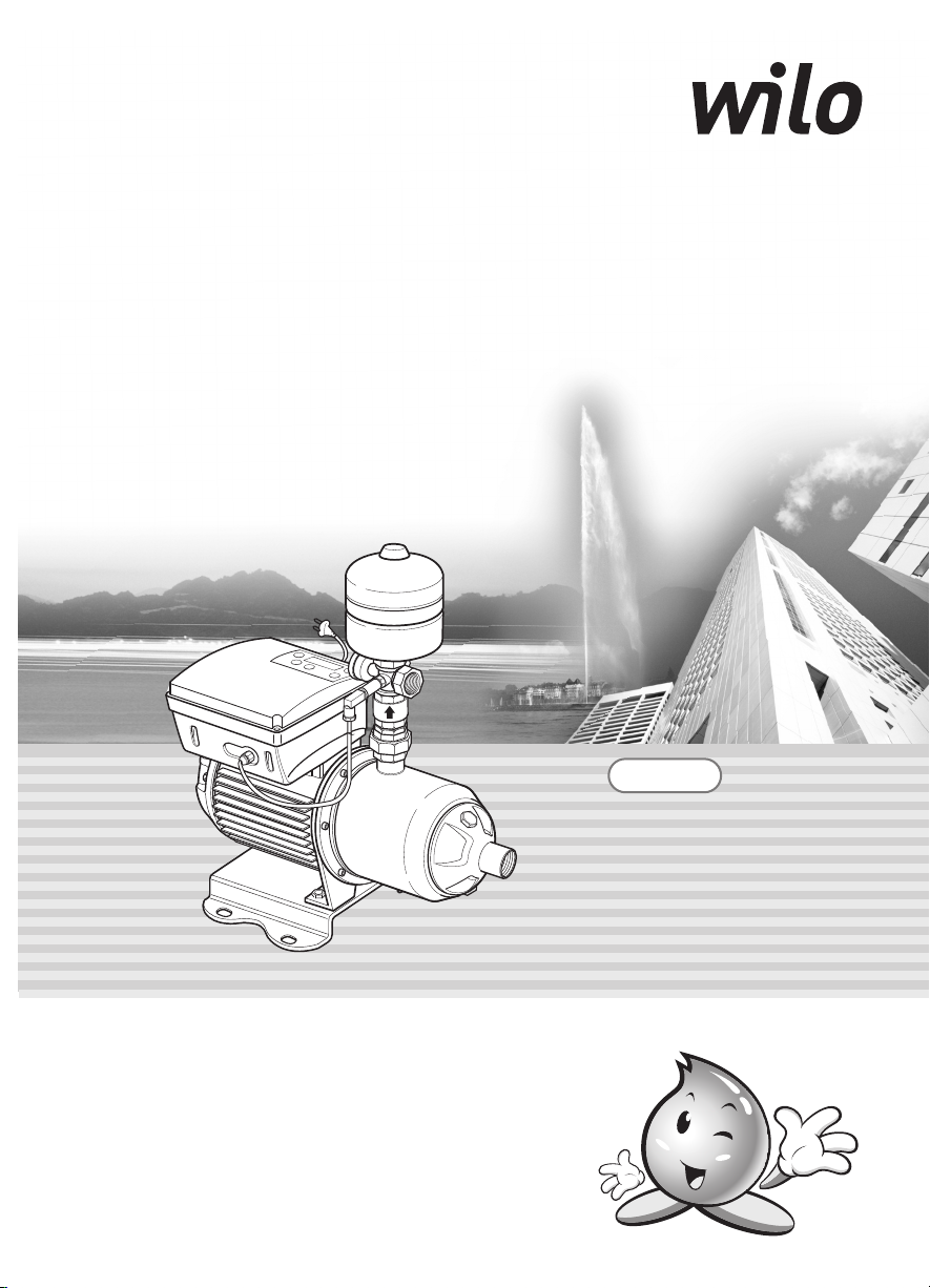
INVERTER PUMP
Installation, Operation, and Maintenance Manual
Models
PBI-L203MA
PBI-L205MA
PBI-L404MA
PBI-L405MA
PBI-L802MA
PBI-L803MA
♣
Before installing and operating the pump, the Safety Instructions must be
thoroughly read for the proper use of the pump.
♣ Before installation, this manual should be completely studied. / Read this
manual completely before any work on your unit.
♣ Keep this manual handy for future reference.
♣ Product warranty is attached to this manual.
♣ ATTENTION: To keep the pump at top efficiency, this manual
should be thoroughly studied.
Page 2
THANK YOU FOR PURCHASING THIS PUMP.
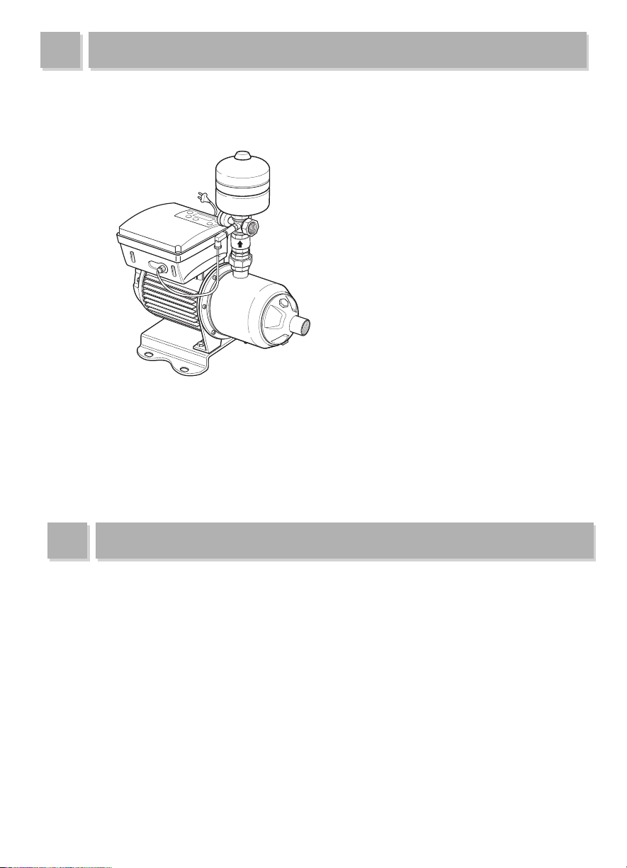
INVERTER PUMP
<PBI-L>
▶ This manual includes installation and operation instructions for PBL-L Model of WILO Pumps.
▶ To keep the pump at top efficiency, follow the recommended instructions in this manual.
▶ In case of lending the pump, this manual should be attached.
I
mproper operation not outlined in this manual may cause defects or physical damage that users are liable for.
▶
▶ The WILO Pumps Customer Service Department is available for customers to ask any questions and to
give an advice on errors on this manual. Call our dealers or headquarter.
▶ Keep this manual handy for future reference.
FEATURES OF THE PUMP
▶ Constant Pressure: The inverter equipped with PID Controller and high-speed digital filter guarantee
constant pressure.
▶ Energy cost saving: AVR(automatic voltage regulator) embedded in the hybrid inverter allows customers
to save energy cost.
▶ Absorption of water hammer shock: The inverter designed to control revolution count absorbs water
hammer shock.
▶ User-friendly handling: Optimized input value reduces customer’s input values.
▶ Low-noise, low-vibration: The pump makes low-noise and low-vibration.
▶ Stainless steel pump: The pump guarantees supply of clean water due to its material, ALL STS304.
▶ Easy installation and maintenance: Package of accessories including piping helps customers easily
install and maintain the pump.
▶ Light weight: Lighter net weight makes installation and transportation easy.
▶ Sophisticated design: The plastic case of the inverter has a sophisticated design.
2
Page 3

APPLICATION OF THE PUMP
▶
The pump is suitable for boosting low water pressure in apartment houses, apartments, weekend
cottages, inns, houses, small sprinklers, school buildings, dormitories, and other buildings,
providingconstant water pressure.
SPECIFICATIONS OF THE PUMP
▶
The embedded converter for constant pressure enables control of the operating pressure depending
on the height of a building.
▶
Pressure gauge is engaged to show pump pressure.
▶
Pressure tank is attached to prevent rapid change of pressure in piping.
▶
The stainless steel pump and brass piping will remain free of rust stains.
※ Water flow rate, water pressure(head), voltage, motor output are referred to on the nameplate.
Basic conditions are:
Ambient temperature
Ambient humidity
Power consumption
Liquid Temperature
0~40°C (32~104°F) Location Indoors
A relative humidity under
90% (no condensation)
Single phase
220V 60Hz
Up to 80°C
Suction condition
Inverter control
Pump
Pressurized condition
centrifugal pump (horizontal
multi-stage stainless steel pump)
VVVF
FEATURES
▶ Adjusting pressure setting
▶ Overpressure protection
▶ Auto restart after electricity failure
▶ Auto restart after correcting errors
▶ Dry running protection and zero flow detection
▶ Optional operating modes: Pressure regulation mode, Constant speed mode, External signal control
▶ Information and alarm signs are indicated on the display, helping easy search
STAINLESS HORIZONTAL MULTI-STAGE PUMP
▶ The pump forms block-typed structure and every pump parts in contact with water is corrosion
resistant. (Approved by KTW and WRC)
▶ The pump is equipped with Mono-Shaft, general-purpose mechanical seal, and plugs for suction and
discharge.
3
Page 4

CONTENTS
Thank you for purchasing our pump.
Follow the recommended instructions in this manual.
Thank you for
purchasing our pump
Features
Application
Contents
Safety Instructions
Transportation and
Installation instructions
Operating instructions
Maintenance
Dimension and Parts
Specifications
Wiring Diagram
Performance Curve
Dimensions
Specifications of the Pump
Connecting Sensors with the Pump
...................................................
................................................
....................................................
..................................
........................................
...........................................
...........................
................................
...................
................
..........................
....................................
............................
..............
10~12
12~13
........
5~9
14
14
15
15
16
17
17
Changing Operating Mode
2
2
3
4
5
Reversing the Rotation of the Pump
Keypad and Display
Indicators
Set Value
Notifying Errors
Default Value for Inverter
Remote control of the pump
Trouble shooting
...............................................
.........................................
.....................................
..............................
.................
.......
...........................
21~22
.................
..............
25~27
18
19
19
20
23
23
24
4
Page 5

SAFETY INSTRUCTIONS
These instructions contain important information which must be followed when installing and operating the
pump. These operating instructions must therefore be read before assembly and commissioning by the installer
and the responsible operator. Both the general safety instructions in the "Safety precautions" section and those
in subsequent sections indicated with danger symbols should be carefully observed.
●
Indication of instructions in the Operating instructions
Safety precautions in these operating instructions which if not followed could cause personal injury are
indicated by the symbol: electrical warnings are indicated with:
The following symbol is used to indicate that by ignoring the relevant safety instructions, damage could be
caused to the pump/machinery and its functions:
ATTENTION!
●
Staff training
The personnel installing the pump must have the appropriate qualifications.
●
Risks incurred by failure to comply with the safety precautions
Failure to comply with the safety precautions could result in personal injury, damage to the pump, or damage
to the installation. Failure to comply with the safety precautions could also invalidate any claim for damages.
In particular, lack of care may lead to problems such as:
-
Failure of important pump or machinery functions,
-P
ersonal injury due to electrical, mechanical and bacteriological causes.
●
Safety precautions for the operator
Existing regulations for accident prevention must be followed. Dangers caused by electrical energy
are to be excluded. Directives issued by the VDE German Association of Electrical Engineers and the local
electricity supply companies are to be observed.
●
Safety information for inspection and assembly
The operator must ensure that all inspection and installation work is carried out by authorized and qualified
specialists who have carefully studied these instructions. Work on the pump/machinery should only be
carried out when the machine has been brought to a standstill.
●
Unauthorized modification and manufacture of spare parts
Alterations to the pump or installation may only be carried out with the manufacturer's consent. The use of
original spare parts and accessories authorized by the manufacturer will ensure safety. The use of any other
parts may invalidate claims invoking the liabilitty of the manufacturer for any consequences.
●
Unauthorized operating methods
The operating safety of the pump or installation supplied can only be guaranteed if it is used in accordance
with paragraph 1 of the operating instructions. The limiting values given in the catalogue or data sheet must
neither be exceeded nor allowed to fall below those specified.
5
Page 6
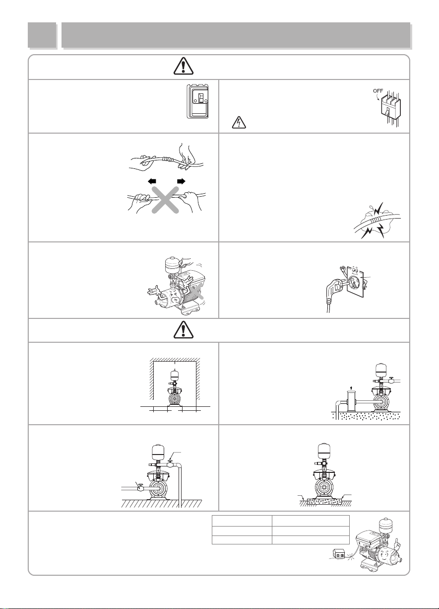
TRANSPORTATION AND INSTALLATION
over 30cm
over 30cm over 30cm
●
Install a breaker of electric leakage
of under 30mA of rated sensitivity
to prevent electric shock.
●
The power cord must not be
bent, tied, pulled
or twisted by force.
Electric leakage,
electric shock, or fire
can occur.
●
Don’t clasp the power cord in transportation
and installation.
The damaged cord may cause
electric leakage or shock.
WARNING!
Breaker
●
Before installation, repair or removal
of the pump, the power supply must be
disconnected.
Breaker
●
Pay special attention to extensions of the power cord.
Any electric leakage or disconnection in the extension
may cause electric shock.
●
How to extend the power cord.
①
Peel off the rubber/plastic insulation of the cable
as long as the connection terminal is.
② Insulate the connection and cover it with rubber tape.
Then tightly cover it over four times
with friction tape.
●
Use a rated outlet with
voltage (220V) fluctuation
of less than
●
To prevent electric shock,
never plug in a power
cord under wet
±
10%.
AC220V
power cord
or plug
conditions.
●
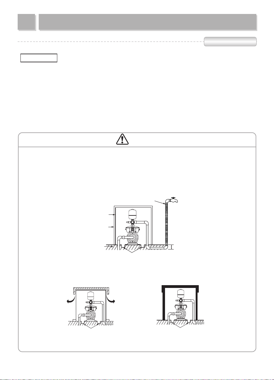
Install the pump where the pump can be
conveniently checked or
repaired after installation.
If the space for the pump
is narrow, make the room
as described on the figure.
●
Install a stop valve on the suction side and the
discharge side of the pump
for easier pump maintenance.
●
When the power cord is extended, a voltage drop
that keeps the pump from operation may be caused.
Refer to the table for extended power cord.
Stop valve
CAUTION!
Stop valve
●
When the pump is highly likely to suck in dust
or foreign material, install a sand filter.
Failure to do so may cause a decline
in pressure and quantity
Sand filter
of pumped water, and
malfunction of the inverter.
●
Concrete the foundation with cement to avoid
pump slant.
Foundation
Length of power cable
shorter than 10
shorter than 200
nominal dimension of the cable
m
larger than 1.5
m
larger than 2.0
㎟
㎟
6
Concrete
Page 7
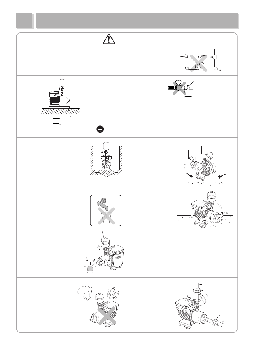
TRANSPORTAION AND INSTALLATION
drinking
water
CAUTION!
●
Minimize the number of elbows to prevent water leakages in the piping
and to decrease water resistance.
ore than 75cm
m
embed a cooper plate
r rod deeply in moist ground.
o
●
When installing the pump,
make waterways to prevent
damage caused by water
leakage. Pay special
attention to a
basement, kitchen, and attic.
●
When the pump is used for
drinking water, a water purifier
must be installed.
※ The pump has no
purification ability.
●
Set an alarm system to notify
the malfunction of the pump.
●
Connect the earth wire before
operation to prevent electric shock
when the electric insulation is faulty.
●
Never get the power plug strained
with water, to prevent electric shock.
ore than 75cm
m
●
Handle the pump with care.
Do not drop.
waterway
●
Set an anti-vibration plate
to absorb the vibration
of the pump.
●
The permitted voltage fluctuation is within 10%
of the rated voltage. Otherwise contact a power
company.
●
The pump should not be connected directly to
public waterworks. Permission from the authority
Gas Pipe
Earth wire
※
NOTE!
• Disconnect the power supply
before connecting the earth wire.
• Gas pipe must not be connected
with earth wire. Otherwise
an explosion may occur.
Damage may occur.
should be granted. This could shorten the life of
the pump.
●
Don’t expose the pump
to direct sunrays or
to rain, otherwise
faulty parts or an electric
shock may be caused.
●
Install unions on the
suction side and
discharge side of the
pump for convenient
maintenance and
repair.
7
Pipe
Union
Union
Pipe
Page 8

운반·설치상의 주의사항
INSTALLATION
Installation process
- The pump should be installed indoors. In case of installing outdoors, set eaves to avoid exposure to wind
and rain, and prevent the pump from freezing.
- The pump should be in pressurized condition. (Recommended suction pressure: 0.2kgf/cm
To prevent dry running, the water tank should always be higher than the suction port of
ATTENTION!
the pump. Keep the minimum suction pressure at all times.
Vent air out from the suction side tank after cleaning it.
Even in a pressurized condition, running the pump with air in the tank or with suction
condition, the mechanical seal may be worn and consequently the rotational part may fall
down upon the stationary part.
Piping
2
)
ATTENTION!
- An elbow close to the pump suction flange should be avoided. Abnormal noise and vibration may occur.
- The piping should be adequately supported on both sides to reduce mechanical stress on the pump
- Make the piping run as short as possible and minimize the number of elbows
- Attach a strainer for filtering foreign objects to the end of the suction piping.
- Install a stop valve on the suction side and the discharge side of the pump to make pump maintenance
easier.
- Install the bypass on the discharge side to make pump maintenance easier.
- When the pressure tank is damaged, the discharge pressure can fluctuate or the piping can leak.
- To minimize noise of the pump, install a flexible joint on the suction piping and the discharge piping, and use
an anti-vibration rubber.
Piping direction
-Piping direction can vary depending on circumstances.
-Piping direction can be adjusted by loosening the union on discharge side.
-Tank is separately packed in shipping.
Pic.1 Pic.2 Pic.3 Pic.4
- Even in a pressurized condition, if an elbow is used, the suction piping should never be
of smaller diameter than the pump suction.
8
Page 9
운반·설치상의 주의사항
over 30cm
INSTALLATION
Wiring
Only a qualified electrician should connect cables. Install a circuit breaker and connect
ATTENTION!
earth wire to prevent any electrical accidents including electric shock.
- The wiring of major parts including the motor and the pressure sensor is already finished. Wiring of earth
and other optional parts should be conducted according to the wiring diagram.
- The power sup ply sh ould be i n a cco rdan ce wit h the rat ed val ue mar ked on th e n ame plat e.
- Before supplying power, check the following:
①
if the circuit breaker at power is suitable (under 30mA of rated sensitivity).
②
if the wiring is correct (connection and wire size).
③
If the connections with motor terminal are tightened (No operation with missing phase).
CAUTION!
In winter, install protections against cold weather.
●
When the pump remains inactive for a long time at temperatures lower than 0°C, the pump body must
be completely empty through the drain valve to prevent possible cracking of the hydraulic components.
●
Bury the horizontal piping at least 30cm under ground.
CAUTION! To prevent a fire, don’t cover the motor or pump with a blanket.
Cover the exposed piping.
lagging
wooden plate
ground
waterway
summer / not humid
waterway waterway
9
winter
Page 10
운반·설치상의 주의사항
USAGE
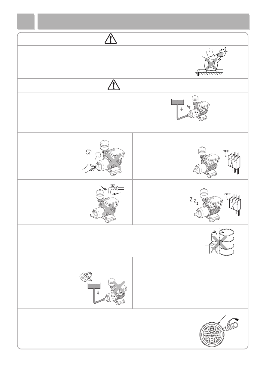
WARNING!
●
To prevent a fire, never wrap the motor of the pump head in a blanket or a cloth
to prevent freezing in cold weather.
The customers are liable for any damage caused by improper wrapping.
CAUTION!
●
Never conduct a shut-off operating under dry running condition
and delivering no water.
The life of the parts may be shortened and explosion may occur.
●
●
Never touch the pump with
a bare hand when the pump
is operating or just stops
operating.
●
If water penetrates into the
motor, malfunction or electric
leakage may occur.
In electricity failure, disconnect the pump with the
power supply. Sudden start up may cause
physical damage.
●
Disconnect the pump if it is unused for a long time.
Otherwise old insulation
may cause electric
shock or fire.
electricity
failure
●
Never use the pump with liquids other than water. A fire may be caused,
when chemicals or flammable liquids including petroleum, alcohol, or
gasoline are used. In addition, the service life of the pump may be
shortened and malfunctions are highly likely to occur.
●
●
Never use hot water over 80°C in the pump.
Rubber parts and packing may be deformed,
and motor may
be damaged.
●
When staring up the pump after a long time of inactivity, check if the rotating
parts turn freely. Turn off the power and insert a screwdriver
in the notch on the motor shaft from the fan side.
Never alter an automatic item into non-automatic
Reconstruction of the pump is prohibited.
●
Any physical damage and property losses
cannot be compensated in this case.
10
Oil
Alcohol
Gasoline
one.
Motor
Page 11

운반·설치상의 주의사항
USAGE
Piping
The suction pipe should be larger than the discharge pipe.
Make the piping run as short as possible and minimize the number of elbows.
The piping should be adequately supported on both sides to reduce mechanical stress on the pump.
Install a stop valve on the suction side and the discharge side of the pump.
*
Test running
① Priming the pump: The pump must not be run dry.
Part Description
1. Foot valve, strainer
2. Stop valve on the
suction side
3. Stop valve on the
discharge side
4. Check valve
5. Air vent screw
6. Drain cap
7. Pipe support
8. Strainer
9. Water tank
10. Piping
11. Monitor protector
12. Union
2
10
9
2 4
HC
MIN
7
3
2 12
6
12
5
8
7
11
1-phase
220V
60Hz
※
Recommended suction pressure : 0.2kgf/cm
※
Maximum suction pressure : 6kgf/cm
- Close the discharge valve (3) and open the air vent screw (5).
- Open the suction valve (2) to fill the pump with water.
- Close the suction valve when water comes out from the air vent screw.
- Close the air vent screw.
② Start-up of the pump
1. Make sure the pump has been primed and open the discharge valve.
2.
Switch on the power and verify that the motor rotates in right direction. Then turn on the power to pump up water.
3. If water is not primed up, power off and reprime the pump.
Make sure that the pump operates without any problem. Then open and close the water tap to verify no leakage.
4.
●
Check the pressure gauge to confirm stable suction and discharge pressure. If the pressure fluctuates,
Reprime the pump.
●
Verify the electronic current flow doesn’t exceed the rated value marked on the nameplate.
2
11
Page 12

MAINTENANCE
WARNING!
●
At first running, if you notice abnormal vibration, noise, or strange smell, turn off and disconnect the
pump from its source and contact the dealer or service center. Continuous operating in this case may
cause fire or electric shock.
●
Don’t ever disassemble or alter the product.
- Fire, electric shock, or physical injury may occur.
- The pump must not be dismantled and repaired except by qualified skilled personnel.
- Contact our service center or dealer to have the pump repaired.
●
When the power cord is broken, the replacement should be carried out by our dealer or other qualified
personnel.
CAUTION!
●
After assembled, the pump should be put to test running.
Incorrect assembly may cause malfunction, electric leakage, or water leakage.
12
Page 13

운반·설치상의 주의사항
MAINTENANCE
Refilling Pressure Tank
WARNING!
- The pressure in the tank must not exceed the rated maximum.
- Regularly check pre-charged gas pressure in the pressure tank.
When checking the pressure, stop the pump and drain the tank. Otherwise the pre-charged gas pressure
cannot be accurately measured.
- Check the pre-charged gas pressure every six months when using proper tank. When refilling the tank,
follow the instructions below:
Completely drai n the tank and open the ca p. R efill the tan k wi th an injector or a compressor.
2
The injected pressure should be 90% of operating pressure or lower by 0.5 kgf/cm
than the pressure.
If it is difficult to drain the tank, stop the pump and start refilling the pressure when pre-charged gas pressure
is far less than needed.
- If the refilled pressure is much lower than operating pressure, the pressure tank may work abnormally.
If the refilled pressure is much higher than operating pressure, the pump may shutdown and restart frequently.
-
Checking Inverter
The wiring and setting of the inverter is already finished before delivery.
WARNING!
Never change any setting except data related to the operation.
The inverter is a semiconductor device that can be damaged by ambient temperature, humidity, and vibration.
To prevent malfunctions, pay attention to following:
①
If there is any problem in wiring connections
③
If there is overheating, discoloration, or abnormal smell
②
If there is abnormal vibrations or noise
- To prerent destruction of IC components, do not preform a voltage test or insulation resistance(mega test).
-
The electronic circuit is embedded in the inverter, so any contact with the inverter may cause static electricity
that can damage parts of the inverter.
Never touch the electronic circuit when repairing and checking the inverter. Otherwise use a ground
connection and earth Chassis when touching it.
- If the bolts and nuts are loosened or rusted, disconnect the power supply, and tighten or replace them.
- If there is a connection defect in the electromagnetic switch or abnormal noise, replace the part.
The timetable below shows how often a part should be replaced.
What to replace How often replace Whenever
Every one year it leaks
-
Every three years abnormal noise occurs.
Every three years
Every three years operation is not certain.
Every three years
Every three years operation is not certain.
it is checked
discrepancy between pressure values
occurs, or value is uncertain.
connection is critically damaged
or malfunction occurs.
Pump/ Motor
Machinery
Control
panel
Mechanical seal
O-ring/ Casket
Motor bearing
Input transmitter
Pressure tank
Relays
PCBs
13
Maintenance time table
NOTE: The timetable is based on the assumption that
after s tartup , the unit has been opera ted at
rated load. So the schedule can be adjusted in
accordance with circumstance and operating
conditions.
Disposal of PCB or electronic parts must be carried
out in accordance with related laws and regulations.
This product includes PCB, so never dispose it in a
general waste collection.
Page 14

DIMENSION AND PARTS
Display
Inverter Cover
Inverter Base
Fan Cover
Motor
Base Plate
운반·설치상의 주의사항
SPECIFICATIONS
Power Cord
Pressure Gauge
Casing
Drain Plug
Pressure Tank
Cross Nipple
Pressure Sensor
Check Valve
Union
Priming Plug
Inverter specifications
Rating output
1.1kW
1.1kW
1.85kW
1.85kW
1.85kW
1.85
kW
kW
Rating capacity
3.0KVA
3.0KVA
4.5KVA
4.5KVA
4.5KVA
4.5KVA
i
Impeller
stage
3
5
4
5
2
3
l
PBI Model Pump
PBI-L203MA
PBI-L205MA
PBI-L404MA
PBI-L405MA
PBI-L802MA
PBI
-
L803MA
※ Pressure transmitter (pressure sensor): rated pressure 16bar, input voltage 5 VDc, output 0~5VCD(Voltage)
※ The volume of pressure tank : 2
MHI203i
MHI205i
MHI404i
MHI405i
MHI802i
MHI803
Motor
output
0.75kW
1.1kW
1.5kW
1.85kW
1.5kW
1.85
Pipe demension
Suction
Discharge
25A 25A
25A 25A
32A 25A
32A 25A
40A
40A
32A
32A
Operation
Pressure
2㎏f/㎠
4㎏f/㎠
4㎏f/㎠
4㎏f/㎠
2㎏f/㎠
2㎏
f
/
㎠
14
Page 15

운반·설치상의 주의사항
WIRING DIAGRAM
Pump
운반·설치상의 주의사항
PERFORMANCE CURVE
(Red, Green, Black)
RS232(Black, Blue, Yellow)
15
Page 16

DIMENSIONS
Model
PBI-L
PBI-L
PBI-L
203MA
205MA
404MA
H
580
580
580
Dimension(mm)
H
1 H2 H3 LL1 L2 ØD1 ØD2
90
120
435
90
90
120
120
435
435
360
425
425
204
252
252
109.5
157.5
157.5
1”
1”
1
1
/4”
Unit(mm)
Weight
(kg)
1”
1”
1”
13
14
19.5
PBI-L
PBI-L
PBI-L
405MA
802MA
803MA
580
5809090
580
90 120
120
435
120
435
435 360 204
16
425
360
252
204
157.5
109.5
109.5
1 1/4
1 1/2
1 1/2
”
”1”1 1/4”
1 1/4”
”
20
18
19
Page 17

운반·설치상의 주의사항
INVERTER DISPLAY
For avoiding electric accidents by high voltage and hazards caused by the leakage of
inverter and condensers, please pull-out the power cord and wait more than 5 minutes.
Every connections (include with potential-free connections) check the poles.
1. Display
Easy display for user
2. Control Button
Use to change the system information
or check.
운반·설치상의 주의사항
SENSOR CONNECTION OF INVERTER PUMP
Keep the power off before connection
- Sensor connection
Pressure auto control mode : Should connect sensor for pressure control
Pressure manual control mode : Sensor is assist function of checking pressure and display
Sensor input
1. Sensor input
Need the qualified person’s help to install the relative pressure for measure the pressure of suction and discharge pipes
17
Page 18

운운·운운운운 운운운운
INVERTER CONTROL BUTTEN EXPLANATION
운운·운운운운 운운운운
STATUS DISPLAY EXPLANATION
Status display when pump stop
Set the pressure in a auto control mode, change the motor
frequency in a manual mode
Pump run, parameter save in a setting mode
Pump stop, parameter cancel in a setting mode
parameter increase in a setting mode, change the status in a
status display menu
parameter decrease in a setting mode, change the status in a
status display menu
pump stop
Current pressure display setting pressure display
Current mode display
Status display when pump running
Current pressure display setting pressure display
18
saved error check
Current frequency display
Page 19

운운·운운운운 운운운운
AUTO CONTROL MODE PRESSURE SETTING
Warning!
운운·운운운운 운운운운
PARAMETER SETTING
Stop the pump before pressure setting
Press the stop button and pump stop
Press the “P” button, display will change the pressure setting
menu.
Press the Auto button and save.
Press the stop button and display will change initial screen.
Ex) How to change setting pressure 2.0 to 3.0 bar
- Open the cover and press the “menu” button in a back of
PCB when change the parameter setting
Press the + or - , change the setting.
Press the + or – move “Mode”,
and press the auto button.
19
Press the + or – move
“Manu”, and press the
auto button.
Press the + or – change
the frequency and press
auto button(save).
Press the stop button, display
will change initial screen.
Page 20

운운·운운운운 운운운운
PARAMETER MENU
※ MENU button is not in front
interface. Open the inverter cover,
menu button is located in back of
interface PCB.
Pump power
Move the
menu by + or -
Rotation of motor
Warming up time
Sensor offset
Press the “stop”
button, move to stop
status in each menu
Dry run pressure setting
Running mode setting
Stop flow time setting
Hi-pressure setting
20
Page 21

운운·운운운운 운운운운
PARAMETER FUNTOIN MENU
1. Pump power
Display Range 750W~1.8KW
Initial setting value
How to check pump power status.
Press auto is move.
~
“750W” or “1.8kW” Blinking.
Press “+” or “-” can change status.
Press “Auto” is save and stop blinking.
Press “Stop” is move to stop status.
2. Motor rotation change
Display Range CCW or CW
Initial setting value
1.1KW
CW
How to change motor rotation.
Press auto is move.
“CW” or “CCW” Blinking.
Press “+” or “-” can change status.
Press “Auto” is save and stop blinking.
Press “Stop” is move to stop status.
21
Page 22

운운·운운운운 운운운운
PARAMETER FUNTOIN MENU
3. Warming-up time change
Display Range 000~999
Initial setting value
Time unit minute
How to change warming-up time.
Press auto is move.
“0” Blinking.
Press “+” or “-” can change status.
Press “Auto” is save and stop blinking.
Press “Stop” is move to stop status.
60
4. Sensor Offset change
How to change sensor offset.
Press auto is move.
“0” Blinking.
Press “+” or “-” can change status.
Press “Auto” is save and stop blinking.
Press “Stop” is move to stop status.
Display Range -0.9 ~ 0.9
Initial setting value
Pressure unit bar
0
22
Page 23

운운·운운운운 운운운운
PARAMETER FUNTOIN MENU
5. Dry-run protection pressure change
How to change dry-run protection pressure.
Press auto is move.
“0.5” Blinking.
Press “+” or “-” can change status.
Press “Auto” is save and stop blinking.
Press “Stop” is move to stop status.
Display Range 0 ~ 9.9
Initial setting value
Pressure unit bar
0.5
6. Running mode change
How to change running mode.
Press auto is move.
Press “+” or “-” can change status.
Press “Auto” is save and stop blinking.
Press “Stop” is move to stop status.
“Auto” or “Manu” Blinking.
Display Range Auto or Manu
Initial setting value
23
Auto
Page 24

운운·운운운운 운운운운
PARAMETER FUNTOIN MENU
7. Stop flow time change
How to change stop flow time.
Press auto is move.
“0” Blinking.
Press “+” or “-” can change status.
Press “Auto” is save and stop blinking.
Press “Stop” is move to stop status.
Display Range 0 ~ 99
Initial setting value
Time unit second
10
8. Abnormal high pressure change
How to change abnormal high pressure.
Press auto is move.
“0” Blinking.
Press “+” or “-” can change status.
Press “Auto” is save and stop blinking.
Press “Stop” is move to stop status.
Display Range
Initial setting value
Pressure unit bar
설정값+ 1.0~15
24
10.0
Page 25

운운·운운운운 운운운운
TROUBLE SHOOTING(INVERTER)
abnormal
high
pressure
Inverter
Error
Over
current
Inverter
oveload
High
voltage
Low
voltage
Error descriptionType
Make an error for protect valve or pipe. When
discharge pressure is higher than abnormal pressure,
inverter make an error.
Make an error for protect inverter. When inverter
hardware alarm is occur(short, earth leakage, or hard
fault), inverter make an error.
Make an error for protect inverter and prevent from
fire by over-current. When impeller bound, overload
are occur, inverter make an error.
Make an error for protect inverter. When alarm is
occur(software trip, pump rated load 130% over),
inverter make an error.
Make an error for safe. When high voltage occur in
DC-Link, inverter make an error.
Make an error for safe and protect inverter. When low
voltage is occur in DC-Link(or AC power voltage),
inverter can’t make control power source and over
current can flow. Inverter make an error.
detecting
delay time
4m sec
4m sec
4m sec --
60m Sec
4m sec
4m sec
delay time
for re-run
10sec after
normal
pressure
return
10sec after
normal
status return
10sec after
normal
status return
10sec after
normal
voltage
return
10sec after
normal
status return
repetition
time
-
-
-
-
-
Code
E-02
E-24
E-23
E-22
E-05
E-04
Dry-run
Bad
suction
Sensor
fault
Communic
ation fault
Make an error for protect pump. When dry-running is
occur, inverter make an error.
Make an error only auto running mode. When bad
suction is occur, inverter make an error.
Make an error only auto running mode. When nosignal or abnormal pressure is occur, inverter make
an error.
When bad communication is occur(control board to
power board), inverter make an error.
30 Sec - 10
10 min -3
4m sec
1 Sce
10sec after
normal
status return
10sec after
normal
status return
-
-
25
E-00
E-06
E-42
E-49
Page 26

운반·설치상의 주의사항
TROUBLE SHOOTING (PUMP)
Trouble
The motor does not
run.
The pump runs, but
doesn’t deliver
water.
Or the suction and
discharge pressure
is too low.
Water delivery is
unstable
The pump
abnormally vibrates
Overheating of the
pump
Motor stopped
due to overload
Cause
Connections are faulty. Tighten loose terminals and repair damaged wire.
Broken power cord Replace the cord.
Motor malfunction Fix or change the motor.
Low voltage
The suction piping leaks.
The mechanical seal leaks. Replace the mechanical seal.
Foreign material clogged the
pump parts.
The suction piping is clogged. Clean the piping.
The pump is not primed.
Low suction pressure and cavitation
Power supply doesn’t reach to the
motor.
The suction piping leaks.
Loosened anchor.
Foreign material clogged the pump.
The pump doesn’t smoothly run. Clean the sticking around the pump.
Power connection failure Check the power of the pump.
Power supply is too low.
Foreign material clogged the
pump.
The ambient temperature is over
40℃.
The input value of the
temperature relay is too low.
Input voltage is too low.
Missing phase
Temperature relay malfunction of
circuit breaker.
The diameter of suction piping is
smaller than that of suction plug.
Strainer or suction piping is partly
clogged.
In case of lower than regulated voltage, contact an
electric power company
Check the connections of piping and completely
cover them up.
Disassemble the pump and clean it.
Reprime the pump. Check the check valve and tighten it.
Compare the piping losses with NPSHa.
Measure the voltage of the motor terminal or
the size of cable wire.
Check the connections of piping and completely
cover them up.
Check anchor bolt / nut and tighten them.
Disassemble the pump and clean it.
Check the voltage of the motor terminal.
Make sure that the voltage varies less than10%.
Disassemble the pump and clean it.
The ambient temperature for the motor should be
lower than
Check the input current and regulate the value as
plated.
Check the power cable and replace it if needed.
Check the power cable and replace it if needed.
Check the terminal of power switch.
Replace it.
The diameter of suction piping should be equal to
that of suction plug.
Disassemble the pump and clean it.
Trouble shooting
40℃.
26
Page 27

운반·설치상의 주의사항
SWITCHING-OF TROUBLE SHOOTING (PUMP)
Trouble
The pump does not
deliver water even
when the water tap is
opened.
The pump does not
stop when the tap is
turned off.
The pump runs even
when water is not
flowing
The pump vibrates
irregolarly (The pump
stops and starts too
often.)
Cause
• Main valve is closed.
• Air is in the pump or piping.
• Pump or motor malfunction
• The motor reverses.
• Water tank is too low.
• Pressure sensor malfunction.
• No power supply.
• The pump is in “STOP” mode.
•Main power, motor, sensors, or
connections are faulty or disconnected.
• Missing phase
• Operating pressure is too low.
•
Input switching off pressure is too high
• Pressure sensors or switches
malfunction.
• Control board malfunction.
• The piping leaks.
• Worn pump or pump backlash
• The piping leaks.
• The check valve leaks.
• The range between the working
pressure and the switching off
pressure is too narrow.
•
Pressure tank malfunction or low pressure
• DFR(Dynamic Flow Range) by piping
Trouble shooting
• Open the main valve.
•
Extract air out from the pump or piping.
• Check and repair the pump.
• In case of three wire connections,
exchange the connection of two wires
each other.
• Fill the tank.
• Move to Pressure regulation mode.
• Check and repair the pump.
• Remove the cause of missing phase.
• Adjust the operating pressure.
.
•
Adjust the input switching-off pressure.
• Check and repair the pump.
• Check and repair the pump.
• Check and repair the pump.
• Check and repair the pump.
• Check and repair the pump.
• Check and repair the pump.
• Adjust the working pressure and
switching off pressure.
•
Check and repair the pump. Fill air into
pressure tank up to rated value.
•
Repair the piping (remove the airpocket).
The pump runs but
does not deliver
expected flow.
The pump does not run in
Pressure regulation
mode.
Th ecircuit breakers trip.
• Input pressure is too low
• Capacity lack of the pump
• Worn pump
• The pump is in Constant speed mode.
• Control board malfunction.
•
Pressure sensors or switches malfunction.
• Pump or motor malfunction.
• Electrical wiring short
• Circuit short or breaker short
• Power short
27
• Adjust the working pressrue.
• Check the specifications of the pump.
• Check and repair the pump.
• Move to Pressure regulation mode.
• Check and repair the pump.
• Check and repair the pump.
• Check and repair the pump.
• Check and repair the pump.
• Check and repair the pump.
• Check and repair the pump.
Page 28

MEMO
Page 29

MEMO
Page 30

MEMO
Page 31

MEMO
Page 32

P/NO. : 3057884 ( Rev.0 )
NOV., 2014 Printed in Korea.
 Loading...