

Wilo MVIL 100, MVIL 300, MVIL, MVIL 500, MVIL 900 Installation And Operating Instructions Manual
Page 1
Wilo-MVIL
D Einbau- und Betriebsanleitung
GB Installation and operating instructions
F Notice de montage et de mise en service
NL Inbouw- en bedieningsvoorschriften
E Instrucciones de instalación y funcionamiento
I Istruzioni di montaggio, uso e manutenzione
P Manual de instalação e funcionamento
TR Montaj ve Kullanma Kılavuzu
GR Οδηγίες εγκατάστασης και λειτουργίας
DK Monterings- og driftsvejledning
S Monterings- och skötselinstruktioner
PL Instrukcja montażu i obsługi
FIN Huolto- ja käyttöohje
RO Instrukcja montazu i obslugi
DK Monterings- og driftsvejledning
Návod k montáži a obsluze
H Beépítési és üzemeltetési utasítás
Montaj ve Kullanma K›lavuzu
PL Instrukcja montażu i obsługi
CZ Návod k montáži a obsluze
RUS Инструкция по монтажу и эксплуатации
EST Paigaldus- ja kasutusjuhend
LV Instalēšanas un ekspluatācijas instrukcijas
LT Montavimo ir naudojimo instrukcija
SK Návod na montáž a obsluhu
SLO Navodila za vgradnjo in vzdrževanje
RO Instrukcja montazu i obslugi
BG Инструкция за монтаж и експлоатация
4.086.201-Ed.1-03/06
Page 2
8
F
B
4Ø13
H
ig. 1
F
ig. 2
Fig. 3
Fig. 4
Fig. 5
Page 3

D Einbau- und Betriebsanleitung 5
GB Installation and operating instructions 11
F Notice de montage et de mise en service 17
NL Inbouw- en bedieningsvoorschriften 23
E Instrucciones de instalación y funcionamiento 29
I Istruzioni di montaggio, uso e manutenzione 35
P Manual de instalação e funcionamento 41
TR Montaj ve Kullanma Kılavuzu 47
GR Οδηγίες εγκατάστασης και λειτουργίας 53
S Monterings- och skötselinstruktioner 59
FIN Huolto- ja käyttöohje 65
DK Monterings- og driftsvejledning 71
H Beépítési és üzemeltetési utasítás 77
PL Instrukcja montażu i obsługi 83
CZ Návod k montáži a obsluze 89
RUS Инструкция по монтажу и эксплуатации 95
EST Paigaldus- ja kasutusjuhend 101
LV Instalēšanas un ekspluatācijas instrukcijas 107
LT Montavimo ir naudojimo instrukcija 113
SK Návod na montáž a obsluhu 119
SLO Navodila za vgradnjo in vzdrževanje 125
RO Instrukcja montazu i obslugi 131
BG Инструкция за монтаж и експлоатация 137
Page 4

1
. General
These installation and operating instructions are
an integral part of the product. They must be
ept readily available at the place where the
k
product is installed. Strict adherence to these
instructions is a precondition for the proper use
and correct operation of the product.
These installation and operating instructions
conform to the relevant version of the product
and the underlying safety standards valid at the
ime of going to press.
t
1.1 Applications
Pumps aimed at clear liquids in building, agriculture and industry areas … (water supply – water
ower - sprinkling, irrigation, high pressure
t
ashing , fire protection, – Lifting of conden-
w
sates – air conditioning – Industrial circuits and
integration in all modular systems.).
- boiler supply (with mandatory by-pass kit).
1.2 Technical characteristics
• Maximum operating pressure (Depending on
types):
102 - 105 Mechanical seal 10 bars
302 - 304 Pump casing 16 bars
502 - 504 Maximum suction
802 - 804 pressure: 6 bars
106 - 112 Mechanical seal 16 bars
305 - 312 Pump casing 16 bars
505 - 512 Maximum suction
805 - 807 pressure: 10 bars
• Temperature range:
(EPDM O’ring and mechanical seal) - 15° to + 90°C
• Ambient temperature (standard): + 40°C maxi
• Maximum suction head: according to NPSH of the
pump
Sound level: Depends on pump size, rotation
speed, working point, motor type: it can exceed
70 dB(A) in 50 Hz and 75 dB(A) in 60 Hz.
2. Safety
These instructions contain important information
which must be followed when installing and
operating the pump. It is therefore imperative
that they be read by both the installer and the
operator before the pump is installed or operated. Both the general safety instructions in this
section and the more specific safety points in
the following sections should be observed.
2.1 Instruction symbols used in this operating man
ual
Symbols
General danger symbol.
Hazards from electrical causes.
NOTE: ...
.
nglish
E
ignal words:
S
DANGER ! Imminently hazardous situation. Will
result in death or serious injury if not avoided.
WARNING ! Risk of (serious) injury. 'Warning'
mplies that failure to comply with the safety
i
instructions is likely to result in (severe) personal injury.
AUTION ! Risk of damage to the pump/instal-
C
lation. ‘Caution’ alerts to user to potential
product damage due to non-compliance with
the safety instructions.
OTE ! Useful information on the handling of the
N
product.
It alerts the user to potential difficulties.
2.2 Personnel qualification
The personnel installing the pump must have the
appropriate qualification for this work.
2.3 Risks incurred by failure to comply with the
safety instructions
Failure to comply with the safety precautions
could result in personal injury or damage to the
pump or installation. Failure to comply with the
safety precautions could also invalidate any claim
for damages.
In particular, failure to comply with these safety
instructions could give rise, for example, to the
following risks:
• Failure of important pump or system functions,
• Failure of specified maintenance and repair
methods
• Personal injury due to electrical, mechanical and
bacteriological causes.
• Damage to property.
2.4 Safety instructions for the operator
The relevant accident precaution regulations
must be observed.
Potential dangers caused by electrical energy
must be excluded. Local or general regulations
[e.g. IEC, VDE, etc.] and directives from local
energy supply companies are to be followed.
2.5 Safety instructions for inspection and assembly
The operator must ensure that all inspection and
assembly work is carried out by authorised and
qualified specialists who have carefully studied
these instructions.
Work on a pump or installation should only be
carried out once the latter has been brought to a
standstill.
-
2.6 Unauthorised modification and manufacture of
spare parts
Changes to the pump/machinery may only be
made in agreement with the manufacturer. The
use of original spare parts and accessories
authorised by the manufacturer will ensure safe
ty. The use of any other parts may invalidate
claims invoking the liability of the manufacturer
for any consequences.
-
11WILO AG 02/2006
Page 5

English
.7 Improper use
2
The operating safety of the pump or installation
can only be guaranteed if it is used in accordance
with paragraph 4 of the operating instructions.
All values must neither exceed nor fall below the
limit values given in the catalogue or data sheet.
3. Transport and interim storage
FREQUENCY 50Hz 60Hz
Speed RPM 2900 3500
Winding* TRI ≤4
* Standard voltage motors: on network (50Hz) ± 10%
- (60Hz) ± 6%
aximun number of starts per hour
M
Motor Power (kW) 0,37 0,55 0,75 1,1 1,5 1,85 2,2 2,5
Direct 100 90 75 60 50 45 40 40
30/400 V220/380V to 254/440V
2
When receiving the material, check that there has
been no damage during the transport. If any defect
has been stated, take the required steps with the
carrier within the allowed time. If the delivered
material is to be installed later on, store it in a dry
place and protect it from impacts and any outside
nfluences (humidity, frost etc...).
i
DANGER ! Due to high position of centre of gravity
and small ground surface of this type of pumps,
beware of unstability during handling to avoid any
falling down and take necessary means to avoid
injuries or damaging.
CAUTION ! Handle the pump carefully so as not to
alter the geometry and the alignment of the
hydraulic unit.
4. Products and accessories
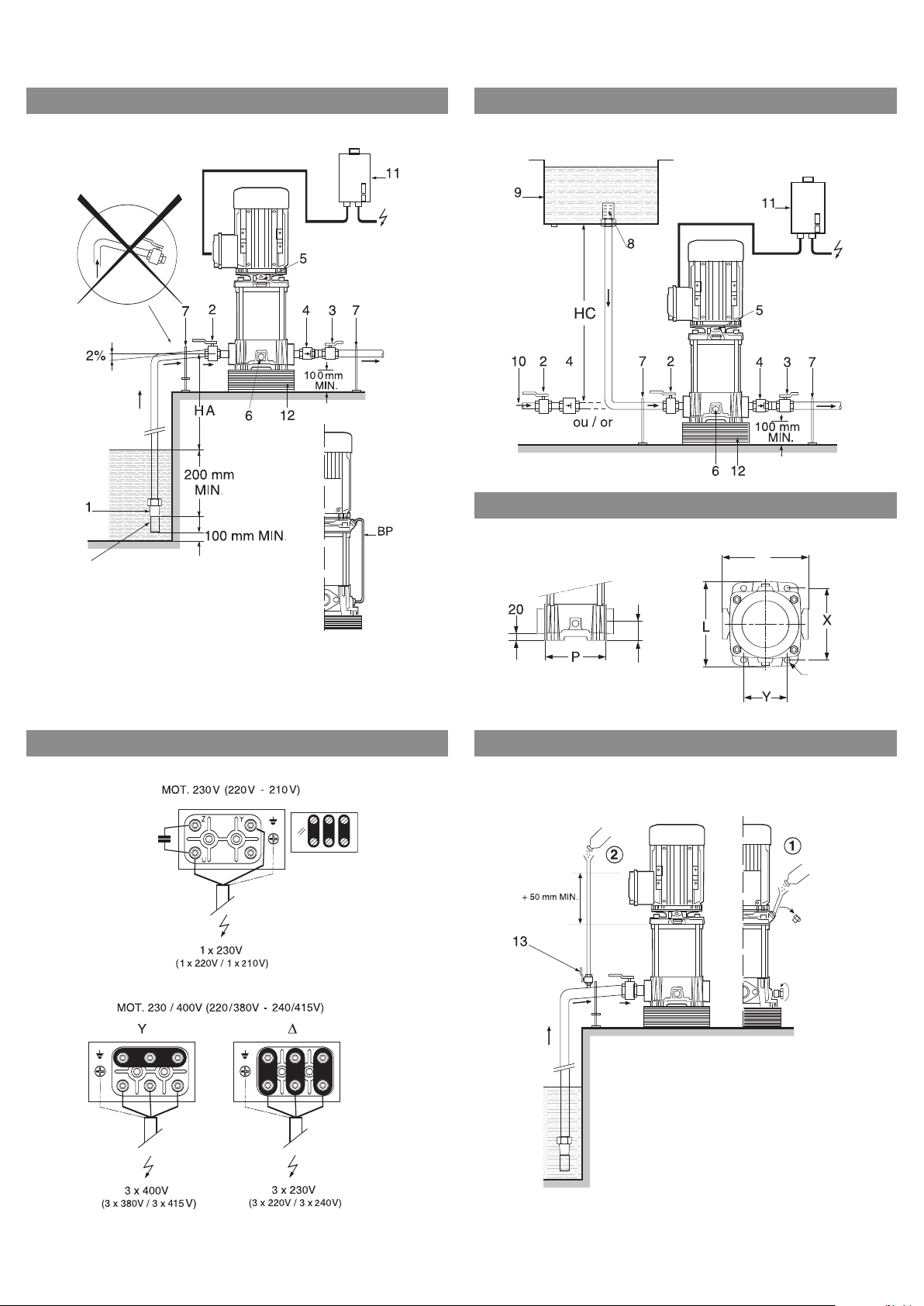
4.1 Description (fig. 1, 2, 5):
1 - Strainer-foot valve
2 - Pump suction valve
3 - Pump discharge valve
4 - Non-return valve
5 - Venting and filling plug
6 - Drain-priming plug
7 - Pipe supports
8 - Strainer
9 - Storage tank
10 - Town water supply
11 - Motor overload release
12 - Foundation block
13 - Cock
HA - Maximum suction head
HC - Minimum inlet pressure
4.2 The pump
Vertical multistage pump (2 to 12 stages) not
self-priming, with ports in line on the same axis
at the bottom part.
Shaft tightness with standard mechanical seal.
Oval Flanges for PN 16 pump casing: pump delivered with oval counterflanges in cast iron for
screw-on tube, gaskets and bolts.
4.3 The motor
Dry motor - 2 poles.
Protection index: IP 54
Insulation class: F
Single phase motor:
- With integrated thermal protection, automatic
reset.
- Capacitor integrated inside the terminal box.
4.4 Accessories (as option)
• By-pass kit • isolating valves • bladder or galvanised tank • tank for antihammer blow effect •
ontrol box • PN 25 weld-on counter-flange
c
(steel) or tapped (stainless steel) • tapped oval
counter-flange PN 16 in stainless steel - motor
overload release • non-return valves • strainer-
oot valve • vibrationless sleeves • dry-running
f
protection kit • flexible collar type Victaulic style
77 • threaded muff joint (stainless steel)…
5. INSTALLATION
Two standard cases:
• fig. 1: pump in suction
• fig. 2: pump under pressure on storage tank (9) or
town water supply (10) with dry-running protection
system.
5.1 Montage
Install the pump in a place easy to reach,protected against frost and as close as possible from the
drawing point.
Install the pump on a concrete block (at least 10
cm high) (fig. 12) and fix with anchor bolts
(installation plan fig. 3).
Foresee an isolating material under the concrete
block (cork or reinforced rubber) to avoid any
noise and vibration transmission into the instal
lation.
Before final tightening of anchor bolts, ensure
that the pump axis is vertical: use shims if necessary.
Bear in mind that the altitude of the installation
place and water temperature may reduce the
suction head of the pump.
Altitude Loss of head Temperature Loss of head
0 m 0 mCL 20 °C 0,20 mCL
500 m 0,60 mCL 30 °C 0,40 mCL
1000 m 1,15 mCL 40 °C 0,70 mCL
1500 m 1,70 mCL 50 °C 1,20 mCL
2000 m 2,20 mCL 60 °C 1,90 mCL
2500 m 2,65 mCL 70 °C 3,10 mCL
3000 m 3,20 mCL 80 °C 4,70 mCL
90 °C 7,10 mCL
100 °C 10,30 mCL
CAUTION !
When the conveyed fluid is above 80°C, plan to
install the pump under pressure.
-
12 WILO AG 02/2006
Page 6

nglish
E
.2 Hydraulic connections
5
By threaded tubes to screw directly on the oval
tapped counterflanges delivered with the pump.
The diameter of the pipe must never be smaller
than the one of the counterflange.
Limit the length of the suction pipe and avoid all
features that cause losses of head (bends, valves,
tapers...).
AUTION ! Connections has to correctly sealed:
C
No air entrance is allowed on the suction pipe
which is showing a mounting declivity (2 %)
(fig. 1).
Use supports or collars so that the pump does
not bear the weight of the pipes.
- The circulation sense of the fluid is indicated on
he identification label of the pump.
t
- Connect the non-return valve to the pump
discharge to protect it from hammer blow
effects.
To pump water with a large content of air or hot
water,we recommend installing the by-pass kit
(fig. 1).
5.3 Electrical connections
The electrical connections and the inspections
have to be done by a qualified electrician and
comply with the applicable local standards.
- The electrical characteristics (frequency, voltage,
nominal current) of the motor are mentionned on
the name plate).
- check if the motor it complies with the mains
supply used.
- The motors must be protected by a circuitbreaker set to the current mentionned on the
name plate of the motor.
- Provide a fuse disconnecting switch (type aM) to
protect the mains supply.
Supply network
- Use an electrical cable conforming with the
National Electric Supply Company.
Three-phase: 4 conductors (3 phases + earth).
If necessary, cut an opening in the terminal box,
fit the cable gland stuffing box and connect the
motor as shown by the diagram inside the cover
of the terminal box (fig. 4).
DO NOT FORGET TO CONNECT TO EARTH.
CAUTION ! A connection error would damage
the motor. The power cable must never touch
the pipe or the pump; make sure that it is sheltered from any humidity.
The electric motors used on the pumps can be
connected to a frequency converter. Strictly follow the instructions given by the data sheet of
the converter's manufacturer.
The converter must not generate voltage peaks
at the motor terminals higher than 850 V and
dU/dt (Voltage/Time variation) higher than
2500 V/µs. If the value of the voltage signal are
higher than those, risk of damage the motor are
to forecast.
n the contrary provide a LC filter (inductance –
I
capacitor) between the converter and the motor.
It must be connected to the motor with a minimum length cable, armoured if necessary.
. Starting up
6
.1 Prior cleaning
6
n hydraulic test is carried out for each pump in
A
our factory. If some water stays inside them. It is
recommended for hygien reasons to clean the
pump before using it with potable water supply.
6.2 Filling - degassing
CAUTION !
riefly.
b
Pump under pressure (fig. 2)
- Close the discharge valve (3),
- Open the venting plug (5), and the suction valve
(2) and completely fill the pump.
Close the venting plug only after water flows out
and complete air exit.
WARNING ! In hot water, a stream of water
may escape from the venting port. Take all
required precautions as regards persons and
motor.
Pump in suction
Two possible cases:
1st CASE (fig. 5-1):
- Close the discharge valve (3), open the suction
valve (2).
- Remove the venting plug (5).
- Unscrew the bottom drain-priming plug (6)
located on the pump casing 4 to 5 turns.
- Put a funnel into the venting plug port and completely fill the pump and the suction pipe.
- After water flows out and total air exit, filling is
complete.
- Screw the venting plug and the bottom drainpriming plug back in.
2nd CASE (fig. 5-2):
Filling can be made easier by fitting on the suction pipe of the pump, a vertical pipe fitted with
a Ø
The length of the pipe must be at least 50 mm
taller than the venting level.
- Close the discharge valve (3), open the suction
valve (2).
- Open the stopcock and the venting plug.
- Unscrew 4 to 5 turns the drain-priming plug (6).
- Fill the pump and the suction pipe completely
until water flows out of the venting plug (5).
- Close the stopcock (which can be left in place),
remove the pipe and close the bleed device (5)
and screw again the drain-priming plug (6).
Never operate the pump dry, even
1/2” stopcock and a funnel.
13WILO AG 02/2006
Page 7

English
ry-running protection
D
To ensure that the pump is always primed,we
recommend to protect it with a pressure switch
or a float switch.
6.3 Check the motor sense of rotation
- With an open-end screwdriver placed in the slot
of the shaft on fan side,make sure that the pump
urns freely without sticking.
t
Three-phase motor
- Switch on the motor by short pressing on the
motor-overload release and check that it turns in
he direction indicated by the arrow located on
t
the identification label of the pump.
- In the opposite case and if the motor had three
phase, cross two phase wires on motor terminal
block or on the switch.
Single-phase motor
The single-phase motors and motors variatiors
are designed for operating in the correct sense of
rotation.
The sense of rotation is adjusted when assem
bling the product and is independent from the
network connection.
6.4 Starting
WARNING ! Depending on conveyed fluid and
running of pump, surface temperature can
exceed 68°C. Take necessary means to avoid
injuries.
7
. Maintenance
ANGER ! Before any operation, switch off the
D
pump(s).
o special maintenance in operation.
N
Keep the pump and the motor perfectly clean.
In case of prolonged stopping, if there is no risk
of frost, it is best not to drain the pump.
The bearing holding the coupling is lubricated for
its total lifetime and does not require any lubrication.
Motors
The bearings are lubricated for their lifetime and
do not require any lubrication.
Mechanical seals
The mechanical seal does not require any main-
enance in operation.
t
It must never operate dry.
Replacement frequencies
The replacement frequency of the mechanical
seal depends on the operating conditions of the
-
pump:
- Temperature and pressure of the conveyed fluid
for the mechanical seal.
- Starting frequency: continuous or intermittent
running.
The replacement frequency of the other components depends on the operating conditions of
the pump like load and ambient temperature.
CAUTION !
flow (closed discharge valve) for more than 10
minutes with cold water (T° C < 40° C) and more
than 5 minutes above 60° C.
We recommend to ensure a minimum flow of
about 10 % of the nominal flow of the pump to
avoid the formation of a vapour lock at the top
of the pump.
- Keep the discharge valve closed.
- Start the pump.
- Open draining plug to drain air. If no water leaks
within 20', close the plug and stop the pump,
then wait 20' to allow air to settle.
- Start again the pump.
- If necessary (particularly if the suction height
exceeds 5 m) repeat these operations.
- If water leaks at draining plug (it means the
pump delivers its pressure), slowly open the dis
charge valve. The pump has to be primed.
- Check pressure stability at discharge with a
manometer, if instability, perfect air draining.
- In case of failure, do the filling in again and start
the operation again.
- To perfect air draining, close the discharge valve
and the draining plug, then stop the pump 20',
start the pump again and open the draining plug.
Do it as long as air comes out.
- Open the discharge valve in order to have the
wished working point.
- Check that the current input does not exceed
the value indicated on the motor data plate.
The pump must not operate at zero
-
14 WILO AG 02/2006
Page 8

8
. Problems, causes and remedies
Faults Causes Remedies
he pump turns but not delivery
T
The pump vibrate Loose on its foundation Check and tighten completely the nuts
The motor overheats Voltage too low Check voltage on terminals of the motor,
The pump delivers insufficient pressure The motor fails to run at its normal
The circuit-breaker device is on The setting of the thermal relay is not
The flow is irregular The suction head (Ha) is not adequate Study again the installation conditions
he internal parts are obstructed by
T
particles
Suction pipe obstructed Clean all the pipes
Air in suction pipes Check tightness of the whole pipe up to
Pump is no more primed Fill the pump to prime again
uction pressure is too low, it causes
S
cavitation noise
he supply voltage of the motor is too
T
low
Particles obstructing the pump Dismantle the pump and clean it
Difficult rotation of the pump Check the pump turns freely without
Bad electrical connection Check the connections to the pump motor
Pump obstructed by particles Dismantle the pump and clean it
Ambient temperature above + 40°C The motor is aimed at operating at a
Coupling failure in the terminal box Be in conformity with the motor plate
speed (particles...)
The motor is defective Replace the motor
Bad filling of the pump Open the bleeding device and drain until
The motor turns in the wrong way
(three-phase motor)
The drain-priming plug is not correctly
tightened
The supply voltage of the motor is too
low
adequate (too low)
The voltage is too low Check the adequate cross-section of the
A phase is cut Check it and change the electrical cable
The thermal relay of the circuit-breaker
is defective
A fuse is off Replace it
The suction pipe has a lower diameter
than the one of the pump
The strainer and the suction pipe are
partially obstructed
ismantle the pump and clean it
D
the pump and make it tight
Check foot valve is tight
oo high loss of head on suction or suc-
T
tion head (check the NPSH of the pump
installed and of the installation)
heck the voltage on the terminals of
C
the motor and the cross-section of the
conductors
of the stud bolts
abnormal sticking
it should be within ± 10 % in 50 Hz or ± 6
% in 60 Hz of the rated voltage
maximum ambient temperature of
+ 40°C
and see figure 4
Dismantle the pump and solve the defect
there are no more air bubbles
Reverse the sense of rotation by interchanging the two phase wires on the
motor terminal box
Check it and screw it again
Check the voltage on the terminals of
the motor and the cross-section of the
conductors
Check the current with an ammeter or
set the value of the current rating on the
motor data plate
conductors of the electrical cable
if necessary
Replace it
and the recommendations described in
this instruction
The suction pipe must have the same
diameter as the suction pump port
Remove and clean
nglish
E
If no solution can be found, please contact your
plumbing and heating specialist or your nearest
Wilo Customer Service or representative.
15WILO AG 02/2006
Page 9

English
9
. Spare parts
Spare parts are ordered via a local specialist dealer and/or Wilo customer service.
In order to avoid queries and incorrect orders,
ake sure to mention all data indicated on the
m
rating plate when placing your order.
Subject to technical alterations !
16 WILO AG 02/2006
Page 10

D EG - Konformitätserklärung
GB EC – Declaration of conformity
F Déclaration de conformité CEE
Hiermit erklären wir, dass die Bauarten der Baureihe :
MVIL 100
Herewith, we declare that this product:
MVIL 300
Par le présent, nous déclarons que cet agrégat :
MVIL 500
MVIL 900
in der gelieferten Ausführung folgenden einschlägigen Bestimmungen entspricht:
in its delivered state comply with the following relevant provisions:
est conforme aux dispositions suivants dont il relève:
EG-Maschinenrichtlinie 98/37/EG
EC-Machinery directive
Directives CEE relatives aux machines
Elektromagnetische Verträglichkeit - Richtlinie 89/336/EWG
Electromagnetic compatibility - directive
i.d.F/ as amended/ avec les amendements suivants:
Compatibilité électromagnétique- directive
91/263/EWG
92/31/EWG
93/68/EWG
Niederspannungsrichtlinie 73/23/EWG
Low voltage directive
i.d.F/ as amended/ avec les amendements suivants :
Direction basse-tension
93/68/EWG
Angewendete harmonisierte Normen, insbesondere:
EN 809
Applied harmonized standards, in particular:
EN 60034-1
Normes harmonisées, notamment:
Dortmund, 25.05.2005
Erwin Prieß
Quality Manager
WILO AG
Nortkirchenstraße 100
44263 Dortmund
Document: 2058815.2
Page 11

N
L
EG-verklaring van overeenstemming
Hiermede verklaren wij dat dit aggregaat in de
g
eleverde uitvoering voldoet aan de volgende
bepalingen:
E
G-richtlijnen betreffende machines 98/37/EG
Elektromagnetische compatibiliteit 89/336/EEG
als vervolg op 91/263/EEG, 92/31/EEG, 93/68/EEG
EG-laagspanningsrichtlijn 73/23/EEG als vervolg
o
p 93/68/EEG
Gebruikte geharmoniseerde normen, in het
bijzonder: 1)
I
Dichiarazione di conformità CE
Con la presente si dichiara che i presenti prodotti
s
ono conformi alle seguenti disposizioni e
direttive rilevanti:
D
irettiva macchine 98/37/CE
Compatibilità elettromagnetica 89/336/CEE e
seguenti modifiche 91/263/CEE, 92/31/CEE,
9
3/68/CEE
D
irettiva bassa tensione 73/23/CEE e seguenti
modifiche 93/68/CEE
Norme armonizzate applicate, in particolare: 1)
E
Declaración de conformidad CE
Por la presente declaramos la conformidad del
p
roducto en su estado de suministro con las
disposiciones pertinentes siguientes:
D
irectiva sobre máquinas 98/37/CE
Directiva sobre compatibilidad electromagnética
89/336/CEE modificada por 91/263/CEE,
9
2/31/CEE, 93/68/CEE
D
irectiva sobre equipos de baja tensión
73/23/CEE modificada por 93/68/CEE
Normas armonizadas adoptadas, especialmente: 1)
P
Declaração de Conformidade CE
Pela presente, declaramos que esta unidade no
s
eu estado original, está conforme os seguintes
requisitos:
Directivas CEE relativas a máquinas 98/37/CE
Compatibilidade electromagnética 89/336/CEE
com os aditamentos seguintes 91/263/CEE,
92/31/CEE, 93/68/CEE
Directiva de baixa voltagem 73/23/CEE com os
aditamentos seguintes 93/68/CEE
Normas harmonizadas aplicadas, especialmente: 1)
S
CE- försäkran
Härmed förklarar vi att denna maskin i levererat
u
tförande motsvarar följande tillämpliga
bestämmelser:
EG–Maskindirektiv 98/37/EG
EG–Elektromagnetisk kompatibilitet – riktlinje
89/336/EWG med följande ändringar
91/263/EWG, 92/31/EWG, 93/68/EWG
EG–Lågspänningsdirektiv 73/23/EWG med
följande ändringar 93/68/EWG
Tillämpade harmoniserade normer, i synnerhet: 1)
N
EU-Overensstemmelseserklæring
Vi erklærer hermed at denne enheten i utførelse
som levert er i overensstemmelse med følgende
r
elevante bestemmelser:
EG–Maskindirektiv 98/37/EG
EG–EMV–Elektromagnetisk kompatibilitet
8
9/336/EWG med senere tilføyelser:
91/263/EWG, 92/31/EWG, 93/68/EWG
EG–Lavspenningsdirektiv 73/23/EWG med senere
tilføyelser: 93/68/EWG
A
nvendte harmoniserte standarder, særlig:
1)
FIN
CE-standardinmukaisuusseloste
Ilmoitamme täten, että tämä laite vastaa
seuraavia asiaankuuluvia määräyksiä:
EU–konedirektiivit: 98/37/EG
Sähkömagneettinen soveltuvuus 89/336/EWG
seuraavin täsmennyksin 91/263/EWG 92/31/EWG,
93/68/EWG
Matalajännite direktiivit: 73/23/EWG seuraavin
täsmennyksin 93/68/EWG
Käytetyt yhteensovitetut standardit, erityisesti: 1)
DK
EF-overensstemmelseserklæring
Vi erklærer hermed, at denne enhed ved levering
overholder følgende relevante bestemmelser:
EU–maskindirektiver 98/37/EG
Elektromagnetisk kompatibilitet: 89/336/EWG,
følgende 91/263/EWG, 92/31/EWG, 93/68/EWG
Lavvolts-direktiv 73/23/EWG følgende
93/68/EWG
Anvendte harmoniserede standarder, særligt: 1)
H
EK. Azonossági nyilatkozat
Ezennel kijelentjük,hogy az berendezés az
alábbiaknak megfelel:
EK Irányelvek gépekhez: 98/37/EG
Elektromágneses zavarás/türés: 89/336/EWG és
az azt kiváltó 91/263/EWG, 92/31/EWG,
93/68/EWG
Kisfeszültségü berendezések irány-Elve:
73/23/EWG és az azt kiváltó 93/68/EWG
Felhasznált harmonizált szabványok, különösen: 1)
CZ
Prohlášení o shodě EU
Prohlašujeme tímto, že tento agregát v dodaném
provedení odpovídá následujícím příslušným
ustanovením:
Směrnicím EU–strojní zařízení 98/37/EG
Směrnicím EU–EMV 89/336/EWG ve sledu
91/263/EWG, 92/31/EWG, 93/68/EWG
Směrnicím EU–nízké napětí 73/23/EWG ve sledu
93/68/EWG
Použité harmonizační normy, zejména: 1)
PL
Deklaracja Zgodności CE
Niniejszym deklarujemy z pełną odpowiedzialnoscią
że dostarczony wyrób jest zgdony z następującymi
dokumentami:
EC–dyrektywa dla przemysłu maszynowego
98/37/EG
Odpowiedniość elektromagnetyczna 89/336/EWG
ze zmianą 91/263/EWG, 92/31/EWG, 93/68/EWG
Normie niskich napięć 73/23/EWG ze zmianą
93/68/EWG
Wyroby są zgodne ze szczegółowymi normami
zharmonizowanymi:
1)
RUS
Деклация о соответствии Европейским
нормам
Настоящим документом заявляем, что данный
агрегат в его объеме поставки соответствует
следующим нормативным документам:
Директивы EC в отношении машин 98/37/EG
Электромагнитная устойчивость 89/336/EWG с
поправками 91/263/EWG, 92/31/EWG,
93/68/EWG
Директивы по низковольтному напряжению
73/23/EWG с поправками 93/68/EWG
Используемые согласованные стандарты и
нормы, в частности : 1)
GR
∆ήλωση προσαρ ογής της Ε.Ε.
∆ηλώνου ε ότι το προϊόν αυτό σ’ αυτή την
κατάσταση παράδοσης ικανοποιεί τις ακόλουθες
διατάξεις :
Οδηγίες EG για ηχανή ατα 98/37/EG
Ηλεκτρο αγνητική συ βατότητα EG-89/336/EWG
όπως τροποποιήθηκε 91/263/EWG 92/31/EWG,
93/68/EWG
Οδηγία χα ηλής τάσης EG–73/23/EWG όπως
τροποποιήθηκε 93/68/EWG
Εναρ ονισ ένα χρησι οποιού ενα πρότυπα,
ιδιαίτερα: 1)
TR
CE Uygunluk Teyid Belgesi
Bu cihazın teslim edildiği ºekliyle aºağıdaki
standartlara uygun olduğunu teyid ederiz:
AB-Makina Standartları 98/37/EG
Elektromanyetik Uyumluluk 89/336/EWG ve takip
eden, 91/263/EWG, 92/31/EWG, 93/68/EWG
Alçak gerilim direktifi 73/23/EWG ve takip eden,
93/68/EWG
Kısmen kullanılan standartlar: 1)
1)
EN 809,
EN 60034-1
Erwin Prieß
Quality Manager
WILO AG
Nortkirchenstraße 100
44263 Dortmund
Page 12

Page 13

 Loading...