

Page 1
Wilo-MVIE 11 --> 22 kW / Wilo-HELIX-VE 11 --> 22 kW
D Einbau- und Betriebsanleitung
GB Installation and operating instructions
F Notice de montage et de mise en service
NL Inbouw- en bedieningsvoorschriften
E Instrucciones de instalación y funcionamiento
I Istruzioni di montaggio, uso e manutenzione
P Manual de instalação e funcionamento
S Monterings- och skötselinstruktioner
DK Monterings- og driftsvejledning
CZ Návod k montáži a obsluze
RUS Инструкция по монтажу и эксплуатации
4093679 – Ed.04-09/08/9704 Ba.
Page 2

Page 3
L
X
P
Y
4 x Ø D
E
1
606 1610
3203 3205
3203 3207
5203 5205
5203 5205
TYPE
2
5
PN
L
PXY
corps
mm mm mm mm
235 235 195 195 35 14
260 260 220 220 35 14
16
25
16
25
16
1606
2
52 190 215 130
260 260 220 220 30 14
E
ØD
mm mm
2
0 12
2207 2209
25
162205
270 190 215 130 5 12
7002 7004
7002 7004
25
16
350 261 280 199 45 14
9501 9503
9501 9503
25
16
350 261 280 199 45 14
5
1
1
7
6
1
13
327
100 mm Min.
200 mm Min.
100 mm
Min.
HA
2%
BP
8
9
12
5
11
3
2
7
74
613
2
4
10
100 mm
Min.
HC
ou / or
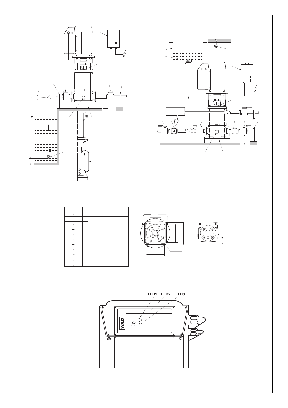
Fig. 1
Fig. 2
Fig. 3
Fig. 4
Page 4
2
1
+ 50 mm
Min.
14
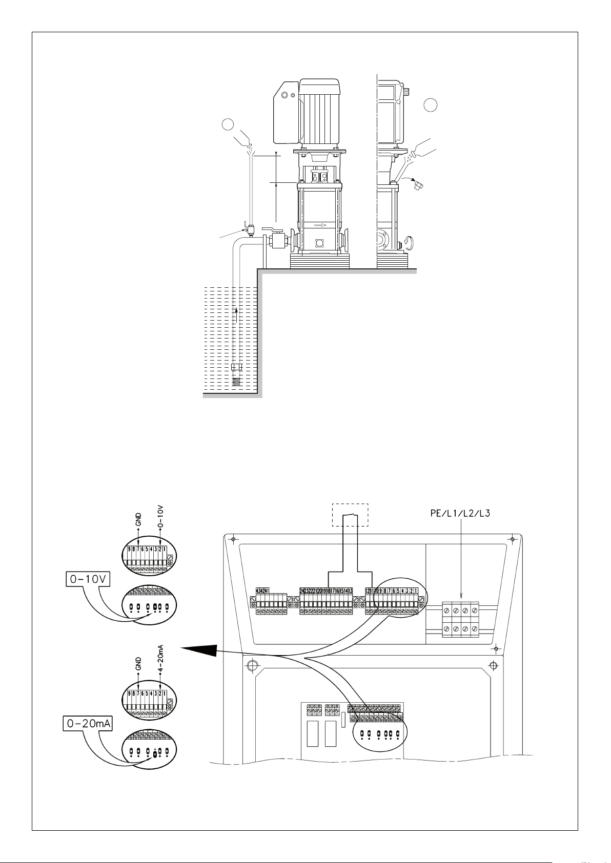
Fig. 5
Fig. 6
Page 5
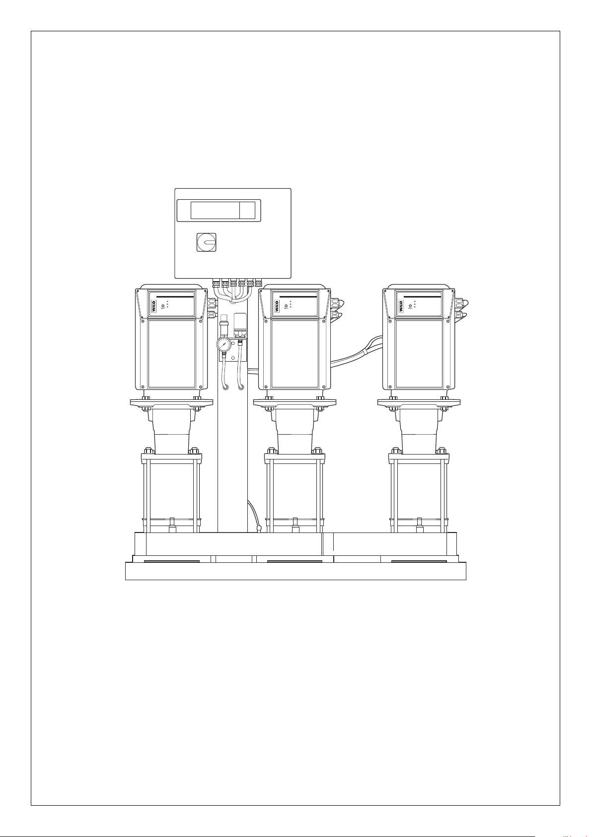
Fig. 7
Page 6

D
1. Allgemeines . . . . . . . . . . . . . . . . . . . . . . . . . . . . . . . . . . . . . . 7
2. Sicherheit . . . . . . . . . . . . . . . . . . . . . . . . . . . . . . . . . . . . . . . . 8
3. Transport und Zwischenlagerung . . . . . . . . . . . . . . . . . . . . . . 8
4. Beschreibung von Produkt und Zubehör . . . . . . . . . . . . . . . . 8
5. Montage . . . . . . . . . . . . . . . . . . . . . . . . . . . . . . . . . . . . . . . . . 9
6. Inbetriebnahme . . . . . . . . . . . . . . . . . . . . . . . . . . . . . . . . . . . 11
7. Wartung . . . . . . . . . . . . . . . . . . . . . . . . . . . . . . . . . . . . . . . . . 12
8. Störungen, Ursachen und Beseitigung . . . . . . . . . . . . . . . . . . 12
GB
1. General . . . . . . . . . . . . . . . . . . . . . . . . . . . . . . . . . . . . . . . . . . 14
2. Safety . . . . . . . . . . . . . . . . . . . . . . . . . . . . . . . . . . . . . . . . . . . 15
3. Transport and interim storage . . . . . . . . . . . . . . . . . . . . . . . . . 15
4. Description and function . . . . . . . . . . . . . . . . . . . . . . . . . . . . . 15
. Assembly . . . . . . . . . . . . . . . . . . . . . . . . . . . . . . . . . . . . . . . . 16
5
6. Starting Up . . . . . . . . . . . . . . . . . . . . . . . . . . . . . . . . . . . . . . . 18
7. Maintenance . . . . . . . . . . . . . . . . . . . . . . . . . . . . . . . . . . . . . . 19
8. Defaults-Causes-Remedies . . . . . . . . . . . . . . . . . . . . . . . . . . 19
F
1. Généralités . . . . . . . . . . . . . . . . . . . . . . . . . . . . . . . . . . . . . . . 21
2. Sécurité . . . . . . . . . . . . . . . . . . . . . . . . . . . . . . . . . . . . . . . . . 22
3. Transport et stockage momentané . . . . . . . . . . . . . . . . . . . . . 22
4. Descriptif et fonctionnement . . . . . . . . . . . . . . . . . . . . . . . . . . 22
5. Installation . . . . . . . . . . . . . . . . . . . . . . . . . . . . . . . . . . . . . . . 23
6. Mise en route . . . . . . . . . . . . . . . . . . . . . . . . . . . . . . . . . . . . . 24
7. Entretien . . . . . . . . . . . . . . . . . . . . . . . . . . . . . . . . . . . . . . . . . 26
8. Anomalies-Détection-Réparation . . . . . . . . . . . . . . . . . . . . . . 26
Page 7

1. General
Installation and service by qualified personnel only
1.1 Uses
Pumps aimed at pumping clear liquids in building, agriculture and
ndustry areas …
i
Water supply, water tower, sprinkling, high pressure washing, boiler
supply (with mandatory by-pass kit) – lifting of condensates – air conditioning – industrial networks and integration in all modular systems.
1.2 Product Data
1.2.1 Connection and electrical data (table 1)
ENGLISH
Temperature range : versions EPDM O’ring and mechanical seal (KTW/WRAS approved versions)
1
) –15 °C to +120 °C
Viton O'ring and mechanical seal (agressiv water) –15 °C to +90 °C
Maximum ambient temperature (standard product) +40 °C maxi
Maximum permissible working pressure : Maximum suction pressure 10 bars
Pump casing PN 16 16 bars
Pump casing PN 25 25 bars
Mains voltages 3~ 400 V (±10%) - 50Hz
3~ 380 V (±6%) - 60Hz
Maximum suction head according NPSH of the pump
Ambient humidity <90 %
Protection index IP 54
Insulation class F
Pump acoustic level tolerance + 3dB (A) : 11 kW 78
15 kW 78
18,5 kW 81
22 kW 81
1
) (WRAS : according to British standard - KTW : according to German standard).
EEMMC
C
This product complies with the standard EN 61800-3 (2nd environment).
WWAARRNNIINNG
G
: in domestic environment this product may cause radio interferences in which case the user may be required to take adequate measures.
Principal dimensions and connection dimensions
(table 2, see also fig. 3)
Types
PN 16 version PN 25 version
LPXYPXY
MVIE mm mm mm
1606 252 190 215 130
1606 to 1610 252 190 215 130
2205 270 190 215 130
2207 to 2209 270 190 215 130
3203 to 3205 235 235 195 195
3203 to 3207 260 260 220 220
5203 to 5205 260 260 220 220 260 220 220
7002 to 7004 350 264 280 199 261 280 199
9501 to 9503 350 264 280 199 261 280 199
When ordering spare parts, please give all the information on the pump/rotor rating plate.
14
Page 8

ENGLISH
1.2.2 Type key
Pump family
(Centrifugal pump,
Multistage vertical,
electronic)
3
Flow rate (m
2 poles/50 Hz)
(
Number of
impellers in row
Power for
MVIE 3203 only
Steel grade :
1 = 1.4301 (AISI 304)
= 1.4404 (AISI 316L)
2
3 = corps GJL-250
+ coating + hydraulics 1.4301 (AISI 304)
Maximum permissible working
ressure (bars)
p
Gaskets – E
Gaskets – V
Mains voltage
3 = 3 400 V
2 = 2 poles
Index of technical evolution
/h)
PDM (KTW/WRAS)
ITON
MVIE 32 03 -11 1 16 E32B
- / / /-/
In particular, failure to comply with these safety precautions could
lead, for example, to risks such as :
• Significant failure of the pump or installation.
• Personal injury due to electrical, mechanical or bacteriological causes.
• Damage to property.
2.4 Safety precautions for the operator
Existing regulations for the prevention of accidents must be followed.
Dangers caused by electrical energy (electric shock or electrocution)
are to be excluded. Safety precautions issued by the local electricity
supply company are to be observed.
2.5 Safety precautions for the installation
The operator must ensure that all inspection and installation work is
carried out by authorised and qualified specialists who have carefully
studied these instructions.
Work on the pump or installation should only be carried out when the
pump is OFF.
2.6 Unauthorized alterations and manufacture of spare parts
Alterations to the pump or installation may only be carried out with the
manufacturer's consent. The use of original spare parts and accessories authorized by the manufacturer will ensure safety. The use of any
other parts may invalidate claims invoking the liability of the manufacturer for any consequences.
2.7 Improper use
The operating safety of the pump or installation supplied can only be
guaranteed if it is used in accordance with paragraph 1 of the operating
instructions.
The limiting values given in the catalogue or data sheet must under no
circumstances be exceeded.
2. Safety
These instructions contain major information, which must be observed
when installing and operating the pump.
These instructions must therefore be by the installer and the responsible operator before the pump is installed or started up.
Both the general safety instructions in the «safety precautions» section
and those in subsequent sections indicated by danger symbols should
be carrefully observed.
2.1 Symbols used in the instruction
Safety precaution which if not followed could cause personal injury:
Safety precaution concerning electrical risks which if not followed could
cause personal injury:
Safety precaution which if not followed could cause damages to the
pump or installation and cause it to malfunction:
CAUTION !
Useful hint to give suggestions and helps the work to be carried out:
NOTE!
2.2 Qualified personnel
The personnel installing the pump must have the appropriate qualifications for this work.
2.3 Risks incurred by failure to comply with the safety precautions
Failure to comply with the safety precautions could result in personal
injury or damage to the pump or installation. Failure to comply with the
safety precautions could also invalidate any claim for damages.
3. Transport and interim storage
When receiving the material, check that there has been no damage
during the transport. If any defect has been stated, take all necessary
steps with the carrier within the allowed time
During transport and in storage the pump must be protected against
moisture, frost and mechanical damage.
Due to high position of centre of gravity and small ground
surface of this type of pumps, beware of instability during
handling to avoid any falling down and take necessary means
to avoid injuries or damaging.
Handle the pump carefully so as not to alter the geometry
and the alignment of the unit.
CAUTION !
In no case the pump must be lifted by the converter,
use some lifting hooks for any handling.
4. Description and function
4.1 Description (fig. 1-2-5)
1 : Strainer-foot valve
2 : Pump suction valve
3 : Pump discharge valve
4 : Non-return valve
5 : Venting and filling plug
6 : Drain-priming plug
7 : Pipe supports or brackets
8 : Strainer
9 : Storage tank
10 : Town water supply
11 : Switch and section switch with fuses
12 : Lifting hook
13 : Foundation block
14 : Cock
BP: By-pass
HA : Maximum suction head
HC : Minimum inlet pressure
15
Page 9

ENGLISH
4.2 Design of pump and motor
• Multistage vertical pump not self-priming, with ports in line on the same
axis in bottom part.
• Asynchronous motor with standardized flange and shaft end for vertical
operation fitted with its converter.
• Motor-pump linked by a coupling with safety guards.
• Shaft sealing by standardized mechanical seal.
• Hydraulic connection:
Round flanges: pump delivered with rings and bolts without counter
flanges (accessories as option).
4.3 Accessories as option
See catalogue or data sheet.
5. Assembly
nstallation and service by qualified personnel only.
CAUTION !
5.1 Installation
Two standard types :
Fig. 1: pump in suction.
Fig. 2: pump under pressure on storage tank (item9) or town water supply (item10).
– Install the pump in a place easy to reach, protected against extrema
conditions (rain and sun in excess, frost) and as close as possible
from the drawing point.
– For heavy pumps provide a point of attachment (lifting hook) in the
pump axis (item12) to facilitate removal.
– Install the pump on a concrete block (at least 10 cm high) (item13)
and fix with anchor bolts (installation plan see fig.3).
– Foresee an insulating material under the concrete block (cork or rein-
forced rubber) to avoid any noise and vibration transmission into the
installation.
– Before final tightening of anchor bolts, ensure that the pump axis is
vertical : use shims if necessary.
CAUTION !
AAllttiittuuddee
0 m 0 mCL 20 °C 0,20 mCL
500 m 0,60 mCL 30 °C 0,40 mCL
1000 m 1,15 mCL 40 °C 0,70 mCL
I
Bear in mind that the altitude of the installation place
and the water temperature may reduce the suction
possibilities of the pump.
Loss of head
TTeemmppeerraattuurree
50 °C 1,20 mCL
60 °C 1,90 mCL
70 °C 3,10 mCL
80 °C 4,70 mCL
90 °C 7,10 mCL
100 °C 10,30 mCL
110 °C 14,70 mCL
120 °C 20,50 mCL
Loss of head
• The direction of the fluid flow is indicated on the identification label of
the pump.
• Limit the length of the suction pipe and avoid all features that cause
losses of head (bends, valves, tapers). Connections have to be
correctly sealed : no air entrance is allowed on the suction
pipe which is showing a mounting declivity of at least 2% (fig.
1).
• Use supports or collars (fig.1 & 2 - item 7) so that the pump does not
CAUTION !
ded to connect the non-return valve to the pump discharge to protect
NOTE!
water, we recommend to install the by-pass kit (fig.1-item BP).
5.3 Electrical connections
The electric connections and inspections have to be carried out by a
qualified electrician and have to comply with the relevant local standards.
• The electric characteristics (frequency, voltage, nominal current) of
he motor-converter are mentioned on the name plate. Check that the
t
motor-converter complies with the mains supply used.
• The electric protection of the motors is integrated into the converter.
The parameters take into account the characteristics of the pump
and must ensure its protection and the one of the motor.
• In case of impedance between earth and neutral point, install a protection before motor-converter.
• Provide a fuse disconnecting switch (type GF) to protect the mains
installation (fig.1 & 2-item11).
• If you have to install a differential circuit-breaker for users protection,
it must have a delay effect. Adjust it according to the current mentioned on the converter label.
• Use power cables conforming with standards
DO NOT FORGET TO CONNECT TO EARTH.
• The electric connection of the converter (fig.6) has to comply with the
ear the weight of the pipes.
b
When the pump is under pressure, it is recommen-
it against hammer blow effects.
To pump water with a large content of air or hot
schemes of the following table :
CAUTION !
A connection error would damage the converter.
The power cable must never touch the pipe or the pump ;
make sure that it is sheltered from any humidity.
• You can change the orientation of the motor-converter by quarter turn
when removing the fixing screws of the motor and reorientating the
motor to the wished position.
Place the screws back.
CAUTION !
sure.
5.2 Hydraulic connections
CAUTION !
runs at maximum frequency and zero flow rate.
• Pump with round flange pump casing : with weld-on or screw-on
tube in the counterflanges (counterflanges available as accessories).
• The diameter of the pipe must never be smaller than the one of the
counter flange.
16
Possible damage of the pump! (cavitation).
Above 80° C, plan to install the pump under pres-
Possible damage of the pump! The installation
has to bear the pressure reached when the pump
Page 10

ENGLISH
Details of electrical connections
– Loosen the screws and remove the converter cover.
CONNECTION TO MAINS SUPPLY POWER TERMINALS
– Connect the cable 4 wires wires ≥ ø4 mm2 No special order
(3 phases + earth)
CONNECTION OF INPUTS/OUTPUTS TERMINAL FOR INPUTS/OUTPUTS (1 to 10)
– Control of the converter by an external (see fig. 6) (See chapter 6 : starting up)
system with a signal (0-10V) or 0-20mA)
A removable jumper has to be placed
according to the type of signal.
- Control with a current signal............................ 0-20mA
put the bridge in low position.
L1 L2 L3 PE
zero volt
urrent input 0-20mA
c
emovable bridge
r
of the phases
654321
7
GND
0-20MA
7654321
GND
- Control with a voltage signal ........................... 0-10V
by default the bridge is in high position,
if not carry out the change.
- Possibility to have a remote control ................ Accessories
(free contact).
zero volt
oltage input 0-10V
v
removable bridge
18 17 16 15 14 12 11
Float switch, pressure gauge for dry-running...
ex :
Remote control
CONNECTION OF THE SERIES CONTACTS TERMINAL FOR SERIES CONTACTS
The speed variator is fitted with an output relay with
free contact aimed for an interface to centralized control
For example : control box, pumps control…
«Available transfer» relay : See fig.6
Bornes : 41 - 42 - 43 Example : 6 defects with a variable time limit on 10 sliding
- feature of the contact .....................................
The relay is actived when the pump runs or
is in a position to run.
When a first defect appears or by mains supply
min12V/10mA
max250V/1A
active relay
minutes according to the following scale :
Final
Stop
cutoff (the pump stops), the relay is no more
active. Information are given to the control box,
regarding the availability of the pump permanently.
transfer ”
“ available
0-10V
The number of defects is stored thanks to a
counter.
If the number of defects is lower than 6 and if
after 10 sliding minutes no new defect has been
detected, so the number of defects of the
counter is reduced of 1.
The pump is permanently stopped the counter
count 6 defects. An impulse on the RESET
button initialize the counter.
rest relay
Defect
appearance
123456
10 sliding minutes
17
Page 11

ENGLISH
Control laws
Control signal 0-20mA
100%
Frequency
n % of
i
he pump
t
rotation
40%
0
2 4
Pump
top
s
ecurity
s
rea
a
Input in current (mA)
20
6. Starting up
CAUTION !
guration mode is the external control 0-10V.
6.1 Configurations
The pump is controlled with an external system (see fig.7)
If the pump is integrated in a booster assembled by ourselves, consult
the booster instructions.
In normal operation the state of the leds is as follows (see fig.4) :
State of Function
LED Light on Flashing Switched off
LED1
RED
LED2 The pump
GREEN turns
LED3 Pump
GREEN alive
6.2 Preliminary rinsing
Each of our pumps is tested regarding hydraulic features in factory,
some water may remain in them. It is recommended for hygien purposes, to carry out a rinsing of the pump before any using with potable
water supply.
6.3 Filling - degassing
CAUTION !
Pump under pressure (see fig. 2)
- Close the discharge valve (item3).
- Open the venting plug (item5), the suction valve (item2) and completely fill the pump.
- Close the venting plug only after water flows out and complete aeration.
- In hot water, a stream of water may escape from the venting plug port.
- Take all required precautions as regards persons and motor-converter.
If the pump is delivered as separate part, not integrated into a system we mounted, the standard confi-
Failure
Detected failure Limit No failure
alarm
The motor is in
acceleration or
deceleration phase
The motor
is stopped
Pump
/
dead
Never operate the pump dry,
even briefly.
Control signal 0-10V
100%
Frequency
n % of
i
he pump
t
rotation
40%
0
1 2
Pump
top
s
ecurity
s
rea
a
Input in a voltage (V)
10
Pump in suction (see fig.1) : two possible cases.
1st case (see fig.5.1)
- Close the discharge valve (fig.1-item3), open the suction valve (fig.1item2).
- Remove the venting plug (fig.1-item5)
- Unscrew about 4 turns the bottom drain-priming plug (fig.1-item 6)
located on the pump casing.
- Put a funnel into the venting plug port and completely fill the pump
and the suction pipe.
- After water flows out and total air exit, filling is achieved.
- Screw the venting plug and the bottom drain-priming plug back in.
2nd case (see fig.5.2)
- Filling can be made easier by fitting on the suction pipe of the pump, a
vertical pipe (fig.5-item14) fitted with a Ø 1/2" stopcock and a funnel.
- The length of the pipe must be at least 50 mm taller than the venting
plug level.
- Close the discharge valve (fig.1-item3), open the suction valve (fig.1item2).
- Open the stopcock (fig.5-item14) and the venting device (fig.1-item5).
- Unscrew about 4 turns the drain-priming plug (fig.1-item 6).
- Completely fill the pump and the suction pipe until water flows out of
the venting plug (fig.1-item5).
- Close the stopcock (fig.5-item14) (which can be left in place), remove
the pipe, close the venting device (fig.1-item5) and screw again the
drain-priming plug (fig.1-item6).
6.4 Starting up
Depending on conveyed fluid and running of pump, surface
temperature can exceed 68°C. Take necessary means to
avoid injuries.
The pump must not operate at zero flow (closed dis-
CAUTION !
charge valve) for more than 10 minutes with cold water
(T°C < 40°C) and more than 5 minutes above 60° C.
- We recommend to ensure a minimum flow of about 10 % of the nominal
flow of the pump to avoid the formation of a vapour lock at the top
of the pump.
- Keep the discharge valve closed.
- Start the pump.
- Open draining plug to drain air. If no water leaks within 20s, close the
plug and stop the pump, then wait 20s to allow air to settle.
18
Page 12

ENGLISH
GR
E
A
SE
- Start again the pump.
- If necessary (particularly if the suction height exceeds 5 m) repeat
these operations.
- If water leaks at draining plug (it means the pump delivers its pressure),
slowly open the discharge valve.
- The pump has to be primed.
- Check pressure stability at discharge with a manometer, if instability,
perfect air draining.
- In case of failure, do the filling in again and start the operation again.
- To perfect air draining, close the discharge valve and the draining plug,
hen stop the pump 20s, start the pump again and open the draining
t
plug. Do it as long as air comes out.
- Open the discharge valve in order to have the wished working point.
- Check that the current input does not exceed the value indicated on
he identification pump plate.
t
7. Maintenance
CAUTION !
Before any operation,
switch off the pump(s).
8. Defaults-Causes-Remedies
Before carrying out any maintenance work, switch off the
pump and ensure that it cannot be switched on again by
unauthorised people.
CAUTION !
Never carry out work on a running pump.
No special maintenance in operation.
Keep the pump and the motor-converter perfectly clean.
In case of prolonged stopping, if there is no risk of frost, it is best not
to drain the pump.
The bearing holding the coupling and the motor bearings are lubricated
for their total lifetime and do not require any lubrication.
On pumps equipped with greaser under bearing box, see regreasing
instructions written on sticker put on it.
MVIE 7004
MVIE 9503/2
On other models, the bearing holding the coupling is lubricated for its
total lifetime.
It is recommended to grease the shaft end as well as the coupling
boring with a high adhering grease (type type D321R Molikote or 8191
Loctite for example) to facilitate any further diassembling.
The mechanical seal does not require any maintenance in operation. It
must never operate dry.
DEFECTS DETECTED BY THE SPEED VARIATOR
All incidents hereafter mentioned give rise to :
- The resting of the ”available transfer” relay.
- The activation of the ”failure transfer” relay when the maximum quantity of defect is reached.
- ligthening of a red LED.
INCIDENTS
8.1 THE PUMP IS
OVERLOADED
8.2 ELECTRICAL
INCIDENTS
8.3 THE MOTOR /
CONVERTER HEATS
CAUSES
a) The Ventilation of the converter
is uncertain :
b) The pump is obstructed
by foreign matters :
c) The pump is locked :
d) The fluid density is too important :
a) The supply of the converter is in
over-or under-voltage :
b) A supply phase is missing :
c) The converter or the motor is
in short-circuit :
a) The ventilation of the converter is uncertain :
b) The motor cooling is uncertain :
REMEDIES
a) Check that the cooling channel is not obstructed.
b) Dismantle the pump, replace the defective
components or clean.
c) Dismantle the pump, clean it and replace the
defective parts.
Possibly mechanical defect of the motor (bearings).
Clean all the pipework.
d) Limit the maximum loading point of the pump
according to the type of fluid.
a) Check the voltage at the converter terminals.
b) Check the supply.
c) Dismantle the motor-converter of the pump and
check it or replace it.
a) Check that the cooling channel is not obstructed
and that fans run correctly.
b) Clean the cooling ribs of the motor.
c) The pump is used in the ambient
temperature higher 40 °C :
-The ”failure transfer” relay is active when the counter reaches 6 failures.
1) If the pump is completely stopped and an intervention on this one is
necessary, cut the supply ; correct the failure, switch on the supply
again.
c) The motor / converter is foreseen to run at a
maximum ambient temperature of + 40 °C.
2) If the failure cause has been suppressed without cutting the converter supply ; the pump must start again after an impulse on the ”reset”
button (See FIG. 4).
- If the defect is major, the action of an after-sales technician is required.
19
Page 13

ENGLISH
Other defects, not detected by the speed variator, due to the
safety to the repairing man.
8.4 THE PUMP TURNS
8.5 THE PUMP IS VIBRATING
pump.
Before any operation, SWITCH OFF the pump(s).
If the liquid is toxic, corrosive or dangerous for human being,
WILO or the qualified person in charge of the repairing must
be informed. In this case, clean the pump to ensure a complete
DEFAULTS
BUT NO DELIVERY
CAUSES
a) The pump does not run quickly enough :
b) The internal parts are obstructed
by particles :
c) Suction pipe are obstructed :
d) Air in suction piping :
e) Suction pressure is too low,
it causes generally
cavitation noise :
a) Loose on its foundation :
REMEDIES
a) Check the adequate adjustment of the po-
tentiometer (conformity to the required points).
b) Let dismantle the pump and clean it.
c) Clean all the pipes.
d) Check tightness of the whole pipe up to be
pump an make it tight.
e) Too high losses of load on suction or suction
head is too high.
(Check the NPSH of the pump installed and
of the installation).
a) Check and tighten completely the nuts of
the stud bolts.
b) Particles obstrucing the pump :
c) Difficult rotation of the pump :
8.6 NO SUFFICIENT
PRESSURE FOR THE
PUMP
8.7 THE FLOW IS
IRREGULAR
If the fault cannot be remedied, please contact your plumbing and heating specialist or
your nearest WILO customer services or representative.
a) The motor speed is not high enough :
b) The motor is defective :
c) Bad filling of the pump :
d) The drain-priming plug is not
fully tightened :
a) The suction head (HA) is not
respected :
b) The suction pipe has a lower
diameter than the one of the pump :
c) The strainer and the suction
pipe are partially obstructed :
b) Have the pump dismantled and clean it.
c) Check the pump turns freely without
abnormal sticking.
a) Check the reference is correctly adjusted
(conformity of the reference points).
b) Replace Motor-converter.
c) Open the venting device and venty until
there are no more air bubbles.
d) Check it and screw it again.
a) Study again the installation conditions and the
recommendations described in this manual.
b) The suction pipe must have the same
diameter as the suction pump port.
c) Remove and clean.
Subject to technical alterations!
20
Page 14

D EG - Konformitätserklärung
GB EC – Declaration of conformity
F Déclaration de conformité CEE
Hiermit erklären wir, dass die Bauarten der Baureihe :
MVIE 11-22 kW
Herewith, we declare that this product:
Par le présent, nous déclarons que cet agrégat :
in der gelieferten Ausführung folgenden einschlägigen Bestimmungen entspricht:
in its delivered state comply with the following relevant provisions:
est conforme aux dispositions suivants dont il relève:
EG-Maschinenrichtlinie 98/37/EG
EC-Machinery directive
Directives CEE relatives aux machines
Elektromagnetische Verträglichkeit - Richtlinie 2004/1008/EG
Electromagnetic compatibility - directive
Compatibilité électromagnétique- directive
Niederspannungsrichtlinie 2006/95/EG
Low voltage directive
Direction basse-tension
Angewendete harmonisierte Normen, insbesondere:
EN 809
Applied harmonized standards, in particular:
EN 50178
Normes harmonisées, notamment:
EN 61800-3
Dortmund, 14.09.2007
Erwin Prieß
Quality Manager
WILO AG
Nortkirchenstraße 100
44263 Dortmund
Document: 2060374.2
Page 15

Page 16

NL
EG-verklaring van overeenstemming
H
iermede verklaren wij dat dit aggregaat in de
g
eleverde uitvoering voldoet aan de volgende
bepalingen:
EG-richtlijnen betreffende machines 98/37/EG
E
lektromagnetische compatibiliteit
2004/1008/EG
EG-laagspanningsrichtlijn 2006/95/EG
Gebruikte geharmoniseerde normen, in het
b
ijzonder:
1)
I
Dichiarazione di conformità CE
C
on la presente si dichiara che i presenti prodotti
s
ono conformi alle seguenti disposizioni e
direttive rilevanti:
Direttiva macchine 98/37/CE
C
ompatibilità elettromagnetica 2004/1008/EG
Direttiva bassa tensione 2006/95/EG
Norme armonizzate applicate, in particolare: 1)
E
Declaración de conformidad CE
P
or la presente declaramos la conformidad del
p
roducto en su estado de suministro con las
disposiciones pertinentes siguientes:
Directiva sobre máquinas 98/37/CE
D
irectiva sobre compatibilidad electromagnética
2004/1008/EG
Directiva sobre equipos de baja tensión
2
006/95/EG
N
ormas armonizadas adoptadas, especialmente:
1
)
P
Declaração de Conformidade CE
Pela presente, declaramos que esta unidade no
seu estado original, está conforme os seguintes
requisitos:
Directivas CEE relativas a máquinas 98/37/CE
Compatibilidade electromagnética 2004/1008/EG
D
irectiva de baixa voltagem 2006/95/EG
N
ormas harmonizadas aplicadas, especialmente:
1)
S
CE- försäkran
Härmed förklarar vi att denna maskin i levererat
utförande motsvarar följande tillämpliga
bestämmelser:
EG–Maskindirektiv 98/37/EG
EG–Elektromagnetisk kompatibilitet –
2004/1008/EG
E
G–Lågspänningsdirektiv 2006/95/EG
Tillämpade harmoniserade normer, i synnerhet: 1)
N
EU-Overensstemmelseserklæring
Vi erklærer hermed at denne enheten i utførelse
s
om levert er i overensstemmelse med følgende
r
elevante bestemmelser:
E
G–Maskindirektiv 98/37/EG
EG–EMV–Elektromagnetisk kompatibilitet
2
004/1008/EG
E
G–Lavspenningsdirektiv 2006/95/EG
Anvendte harmoniserte standarder, særlig: 1)
FIN
CE-standardinmukaisuusseloste
Ilmoitamme täten, että tämä laite vastaa
seuraavia asiaankuuluvia määräyksiä:
EU–konedirektiivit: 98/37/EG
Sähkömagneettinen soveltuvuus 2004/1008/EG
Matalajännite direktiivit: 2006/95/EG
Käytetyt yhteensovitetut standardit, erityisesti: 1)
DK
EF-overensstemmelseserklæring
Vi erklærer hermed, at denne enhed ved levering
o
verholder følgende relevante bestemmelser:
EU–maskindirektiver 98/37/EG
Elektromagnetisk kompatibilitet: 2004/1008/EG
Lavvolts-direktiv 2006/95/EG
Anvendte harmoniserede standarder, særligt: 1)
H
EK. Azonossági nyilatkozat
Ezennel kijelentjük,hogy az berendezés az
alábbiaknak megfelel:
EK Irányelvek gépekhez: 98/37/EG
Elektromágneses zavarás/türés: 2004/1008/EG
Kisfeszültségü berendezések irány-Elve:
2006/95/EG
Felhasznált harmonizált szabványok, különösen: 1)
CZ
Prohlášení o shodě EU
Prohlašujeme tímto, že tento agregát v dodaném
provedení odpovídá následujícím příslušným
ustanovením:
Směrnicím EU–strojní zařízení 98/37/EG
Směrnicím EU–EMV 2004/1008/EG
Směrnicím EU–nízké napětí 2006/95/EG
Použité harmonizační normy, zejména: 1)
PL
Deklaracja Zgodności CE
Niniejszym deklarujemy z pełną odpowiedzialnoscią
że dostarczony wyrób jest zgdony z następującymi
dokumentami:
EC–dyrektywa dla przemysłu maszynowego
98/37/EG
Odpowiedniość elektromagnetyczna
2004/1008/EG
Normie niskich napięć 2006/95/EG
Wyroby są zgodne ze szczegółowymi normami
zharmonizowanymi: 1)
RUS
Деклация о соответствии Европейским
нормам
Настоящим документом заявляем, что данный
агрегат в его объеме поставки соответствует
следующим нормативным документам:
Директивы EC в отношении машин 98/37/EG
Электромагнитная устойчивость
2004/1008/EG
Директивы по низковольтному напряжению
2006/95/EG
Используемые согласованные стандарты и
нормы, в частности : 1)
GR
∆ήλωση προσαρ ογής της Ε.Ε.
∆ηλώνου ε ότι το προϊόν αυτό σ’ αυτή την
κατάσταση παράδοσης ικανοποιεί τις ακόλουθες
διατάξεις :
Οδηγίες EG για ηχανή ατα 98/37/EG
Ηλεκτρο αγνητική συ βατότητα -2004/1008/EG
Οδηγία χα ηλής τάσης 2006/95/EG
Εναρ ονισ ένα χρησι οποιού ενα πρότυπα,
ιδιαίτερα: 1)
TR
CE Uygunluk Teyid Belgesi
Bu cihazın teslim edildiği ºekliyle aºağıdaki
standartlara uygun olduğunu teyid ederiz:
AB-Makina Standartları 98/37/EG
Elektromanyetik Uyumluluk 2004/1008/EG
Alçak gerilim direktifi 2006/95/EG
Kısmen kullanılan standartlar: 1)
1)
EN 809
EN 50178
EN 61800-3
Erwin Prieß
Quality Manager
WILO AG
Nortkirchenstraße 100
44263 Dortmund
Page 17

WILO SE
Nortkirchenstraße 100
44263 Dortmund
Germany
T +49 231 4102-0
F +49 231 4102-7363
wilo@wilo.de
www.wilo.com
Algeria
Bad Ezzouar, Dar El Beida
T +213 21 247979
chabane.hamdad@salmson.fr
Armenia
375001 Yerevan
T +374 10 544336
info@wilo.am
Bosnia and Herzegovina
71000 Sarajevo
T +387 33 714510
zeljko.cvjetkovic@wilo.ba
Georgia
0177 Tbilisi
T +995 32317813
info@wilo.ge
Macedonia
1000 Skopje
T +389 2 3122058
valerij.vojneski@wilo.com.mk
Moldova
2012 Chisinau
T +373 2 223501
sergiu.zagurean@wilo.md
Rep. Mongolia
Ulaanbaatar
T +976 11 314843
wilo@magicnet.mn
Tajikistan
734025 Dushanbe
T +992 37 2232908
farhod.rahimov@wilo.tj
Turkmenistan
744000 Ashgabad
T +993 12 345838
wilo@wilo-tm.info
Uzbekistan
700046 Taschkent
sergej.arakelov@wilo.uz
August 2008
Wilo – International (Subsidiaries)
Wilo – International (Representation offices)
Argentina
W
ILO SALMSON
A
rgentina S.A.
C1270ABE Ciudad
Autónoma de Buenos Aires
T +54 11 43015955
info@salmon.com.ar
A
ustria
WILO Handelsges. m.b.H.
1
230 Wien
T
+43 507 507-0
office@wilo.at
Azerbaijan
WILO Caspian LLC
1065 Baku
T +994 12 5962372
info@wilo.az
Belarus
WILO Bel OOO
220035 Minsk
T +375 17 2503393
wilobel@wilo.by
Belgium
WILO SA/NV
1083 Ganshoren
T +32 2 4823333
info@wilo.be
Bulgaria
WILO Bulgaria Ltd.
1125 Sofia
T +359 2 9701970
info@wilo.bg
Canada
WILO Canada Inc.
Calgary, Alberta T2A 5L4
T +1 403 2769456
bill.lowe@wilo-na.com
China
WILO China Ltd.
101300 Beijing
T +86 10 80493900
wilobj@wilo.com.cn
C
roatia
WILO Hrvatska d.o.o.
10090 Zagreb
T
+38 51 3430914
w
ilo-hrvatska@wilo.hr
Czech Republic
WILO Praha s.r.o.
25101 Cestlice
T +420 234 098711
info@wilo.cz
Denmark
WILO Danmark A/S
2690 Karlslunde
T +45 70 253312
wilo@wilo.dk
Estonia
WILO Eesti OÜ
12618 Tallinn
T +372 6509780
info@wilo.ee
Finland
WILO Finland OY
02330 Espoo
T +358 207401540
wilo@wilo.fi
France
WILO S.A.S.
78390 Bois d'Arcy
T +33 1 30050930
info@wilo.fr
Great Britain
WILO (U.K.) Ltd.
DE14 2WJ BurtonUpon-Trent
T +44 1283 523000
sales@wilo.co.uk
Greece
WILO Hellas AG
14569 Anixi (Attika)
T +302 10 6248300
wilo.info@wilo.gr
Hungary
WILO Magyarország Kft
2
045 Törökbálint
(Budapest)
T
+36 23 889500
wilo@wilo.hu
I
reland
W
ILO Engineering Ltd.
Limerick
T
+353 61 227566
sales@wilo.ie
Italy
WILO Italia s.r.l.
20068 Peschiera
Borromeo (Milano)
T +39 25538351
wilo.italia@wilo.it
Kazakhstan
WILO Central Asia
050002 Almaty
T +7 727 2785961
in.pak@wilo.kz
Korea
WILO Pumps Ltd.
621-807 Gimhae
Gyeongnam
T +82 55 3405800
wilo@wilo.co.kr
Latvia
WILO Baltic SIA
1019 Riga
T +371 67 145229
mail@wilo.lv
Lebanon
WILO SALMSON
Lebanon
12022030 El Metn
T +961 4 722280
wsl@cyberia.net.lb
Lithuania
W
ILO Lietuva UAB
03202 Vilnius
T +370 5 2136495
m
ail@wilo.lt
The Netherlands
WILO Nederland b.v.
1948 RC Beverwijk
T +31 251 220844
i
nfo@wilo.nl
Norway
WILO Norge AS
0901 Oslo
T +47 22 804570
wilo@wilo.no
Poland
WILO Polska Sp. z.o.o.
05-090 Raszyn
T +48 22 7026161
wilo@wilo.pl
Portugal
Bombas Wilo-Salmson
Portugal Lda.
4050-040 Porto
T +351 22 2080350
bombas@wilo.pt
Romania
WILO Romania s.r.l.
077040 Com. Chiajna
Jud. Ilfov
T +40 21 3170164
wilo@wilo.ro
Russia
WILO Rus ooo
123592 Moscow
T +7 495 7810690
wilo@orc.ru
Saudi Arabia
WILO ME - Riyadh
Riyadh 11465
T +966 1 4624430
wshoula@wataniaind.com
S
erbia and Montenegro
WILO Beograd d.o.o.
11000 Beograd
T +381 11 2851278
o
ffice@wilo.co.yu
Slovakia
WILO Slovakia s.r.o.
8
2008 Bratislava 28
T
+421 2 45520122
w
ilo@wilo.sk
Slovenia
WILO Adriatic d.o.o.
1000 Ljubljana
T +386 1 5838130
wilo.adriatic@wilo.si
South Africa
Salmson South Africa
1610 Edenvale
T +27 11 6082780
errol.cornelius@
salmson.co.za
Spain
WILO Ibérica S.A.
28806 Alcalá de Henares
(Madrid)
T +34 91 8797100
wilo.iberica@wilo.es
Sweden
WILO Sverige AB
35246 Växjö
T +46 470 727600
wilo@wilo.se
Switzerland
EMB Pumpen AG
4310 Rheinfelden
T +41 61 83680-20
info@emb-pumpen.ch
Taiwan
WILO-EMU Taiwan Co. Ltd.
1
10 Taipeh
T +886 227 391655
n
elson.wu@
w
iloemutaiwan.com.tw
Turkey
W
ILO Pompa Sistemleri
S
an. ve Tic. A.S¸.
3
4530 Istanbul
T +90 216 6610211
wilo@wilo.com.tr
Ukraina
WILO Ukraina t.o.w.
01033 Kiew
T +38 044 2011870
wilo@wilo.ua
Vietnam
Pompes Salmson Vietnam
Ho Chi Minh-Ville Vietnam
T +84 8 8109975
nkm@salmson.com.vn
United Arab Emirates
WILO ME - Dubai
Dubai
T +971 4 3453633
info@wilo.com.sa
USA
WILO-EMU USA LLC
Thomasville,
Georgia 31792
T +1 229 5840097
info@wilo-emu.com
USA
WILO USA LLC
Melrose Park, Illinois 60160
T +1 708 3389456
mike.easterley@
wilo-na.com
Page 18

WILO SE
Nortkirchenstraße 100
44263 Dortmund
Germany
T 0231 4102-0
F 0231 4102-7363
wilo@wilo.de
www.wilo.de
G1 Nord
WILO SE
Vertriebsbüro Hamburg
Beim Strohhause 27
20097 Hamburg
T 040 5559490
F 040 55594949
hamburg.anfragen@wilo.de
G2 Ost
WILO SE
Vertriebsbüro Berlin
Juliusstraße 52–53
12051 Berlin-Neukölln
T 030 6289370
F 030 62893770
berlin.anfragen@wilo.de
G3 Sachsen/Thüringen
WILO SE
Vertriebsbüro Dresden
Frankenring 8
01723 Kesselsdorf
T 035204 7050
F 035204 70570
dresden.anfragen@wilo.de
G4 Südost
WILO SE
Vertriebsbüro München
Landshuter Straße 20
85716 Unterschleißheim
T 089 4200090
F 089 42000944
muenchen.anfragen@wilo.de
G5 Südwest
WILO SE
Vertriebsbüro Stuttgart
Hertichstraße 10
71229 Leonberg
T 07152 94710
F 07152 947141
stuttgart.anfragen@wilo.de
G6 Rhein-Main
WILO SE
Vertriebsbüro Frankfurt
An den drei Hasen 31
61440 Oberursel/Ts.
T 06171 70460
F 06171 704665
frankfurt.anfragen@wilo.de
G7 West
WILO SE
Vertriebsbüro Düsseldorf
Westring 19
40721 Hilden
T 02103 90920
F 02103 909215
duesseldorf.anfragen@wilo.de
Kompetenz-Team
Gebäudetechnik
WILO SE
Nortkirchenstraße 100
44263 Dortmund
T 0231 4102-7516
T 01805 R•U•F•W•I•L•O*
7•8•3•9•4•5•6
F 0231 4102-7666
Kompetenz-Team
Kommune
Bau + Bergbau
WILO EMU GmbH
Heimgartenstraße 1
95030 Hof
T 09281 974-550
F 09281 974-551
Werkskundendienst
Gebäudetechnik
Kommune
Bau + Bergbau
Industrie
WILO SE
Nortkirchenstraße 100
44263 Dortmund
T 0231 4102-7900
T 01805 W•I•L•O•K•D*
9•4•5•6•5•3
F 0231 4102-7126
Erreichbar Mo–Fr von
7–17 Uhr.
Wochenende und feiertags
9–14 Uhr elektronische
Bereitschaft mit
Rückruf-Garantie!
–Kundendienst-Anforderung
–Werksreparaturen
–Ersatzteilfragen
–Inbetriebnahme
–Inspektion
–Technische Service-Beratung
–Qualitätsanalyse
Wilo-International
Österreich
Zentrale Wien:
WILO Handelsgesellschaft mbH
Eitnergasse 13
1230 Wien
T +43 507 507-0
F +43 507 507-15
Vertriebsbüro Salzburg:
Gnigler Straße 56
5020 Salzburg
T +43 507 507-13
F +43 507 507-15
Vertriebsbüro Oberösterreich:
Trattnachtalstraße 7
4710 Grieskirchen
T +43 507 507-26
F +43 507 507-15
Schweiz
EMB Pumpen AG
Gerstenweg 7
4310 Rheinfelden
T +41 61 83680-20
F +41 61 83680-21
Standorte weiterer
Tochtergesellschaften
Argentinien, Aserbaidschan,
Belarus, Belgien, Bulgarien,
China, Dänemark, Estland,
Finnland, Frankreich,
Griechenland, Großbritannien,
Irland, Italien, Kanada,
Kasachstan, Korea, Kroatien,
Lettland, Libanon, Litauen,
Niederlande, Norwegen,
Polen, Portugal, Rumänien,
Russland, Saudi-Arabien,
Schweden, Serbien und
Montenegro, Slowakei,
Slowenien, Spanien,
Südafrika, Taiwan,
Tschechien, Türkei, Ukraine,
Ungarn, Vereinigte Arabische
Emirate, Vietnam, USA
Die Adressen finden Sie unter
www.wilo.de oder
www.wilo.com.
Stand August 2008
Erreichbar Mo–Fr von 7–18 Uhr.
–Antworten auf
– Produkt- und Anwendungsfragen
– Liefertermine und Lieferzeiten
–Informationen über Ansprechpartner vor Ort
–Versand von Informationsunterlagen
* 14 Cent pro Minute aus dem deutschen Festnetz
der T-Com. Bei Anrufen aus Mobilfunknetzen
sind Preisabweichungen möglich.
Wilo-Vertriebsbüros in Deutschland
 Loading...