

Page 1
2047640-Ed.02/2007-03-DDD
Wilo-Drain VC 32 / VC 40
D Einbau- und Betriebsanleitung
GB Installation and Operating Instructions
F Notice de montage et de mise en service
RUS
Instrukcii po vvodu v qkspluataciœ i
montaΩu
Page 2
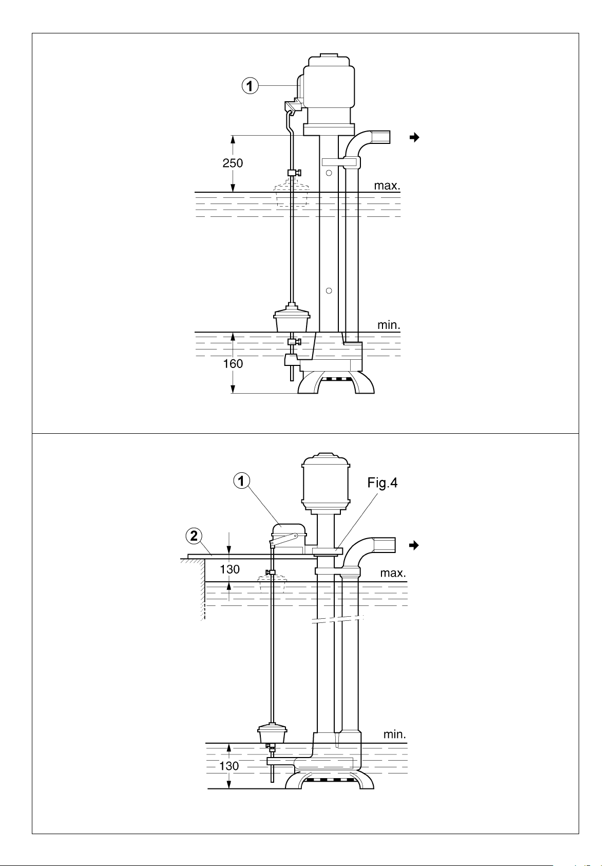
Fig. 1
Fig. 2
Page 3
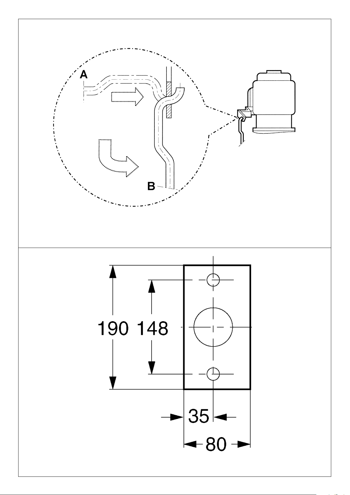
Fig. 3
Fig. 4
Page 4

Fig. 5
VC 32
Page 5

Fig. 6
VC 40
Page 6

ENGLISH
1 General Information
Installation and service by qualified personnel only!
1.1 Uses
The pumps in the VC series are suitable for pumping chemically neutral, lightly soiled wastewater, condensate and clear fluids containing solids of 5 to 7 mm Ø from pump shafts from
boiler and heating installations and basements at risk of flooding.
These pumps must not be used:
– to pump raw sewage containing faeces
– in areas where there is a risk of explosion
– to pump drinking water.
Local regulations must be observed.
1.2 Product data
1.2.1 Rating plate VC 32 / 10 1~230
VC 32 / 10 3~400
VC 40 / 20 3~400
Series: Vertical Cast Iron
Nominal width of pipe mount [mm]
Maximum delivery head 10, 20 [m]
1~230 = single-phase motor
3~400 = three-phase motor
1.2.2 Connection and electrical data
– max. permissible solid grain size: Ø 5 (VC 32),
Ø 7 (VC 40)
– Power supply: 1 ~ 230 V, ±10%
3 ~ 230/400 V, ±10%
– Mains frequency: 50 Hz
– Protection category (motor): IP 54
– Insulation class (motor): F
– Speed: max. 2900
1
/min
– Sound pressure level: < 70 dB(A)
– max. current consumption: see rating plate
– Power input P1: see rating plate
– Rated motor power P2: see rating plate
– Operating mode S1: 2 hours / day
– Operating mode S3 (optimum): Intermittent service, 25%
(2.5 min. mode, 7.5 min.
break).
– Recommended operating frequency: 20
1
/h
– Nominal width of connection size: 1" (VC 32),
1|" (VC 40)
– admissible temperature range of the flow medium:
+5 to 95°C
When ordering spare parts, please give all the information on
the pump rating plate.
2 Safety
These instructions contain important information which must
be observed when installing and operating the pump. These
operating instructions must therefore be read by the installer
and the responsible operator before assembly and commissioning. In addition to the general safety instructions laid down
in the Safety section, the special safety instructions laid down
in the following sections are also to be observed.
2.1 Danger symbols used in these operating instructions
Safety precautions contained in these operating instructions
which if not followed could cause personal injury are indicated
by the symbol:
,
with the following symbol used to indicate electrical voltage:
The symbol below indicates that by ignoring the relevant safety
instructions, damage could be caused to the pump or installation:
2.2 Staff training
The personnel installing the pump must have the appropriate
qualifications for this work.
2.3 Risks incurred by failure to comply with the safety
precautions
Failure to comply with the safety precautions could result in
personal injury or damage to the pump or installation. Failure
to comply with the safety precautions could also invalidate any
claim for damages.
In particular, failure to comply may lead to problems such as:
– Failure of important pump or installation functions,
– Personal injury due to electrical, mechanical or bacteriologi-
cal causes.
2.4 Safety precautions for the operator
Existing regulations for the prevention of accidents must be
followed.
All risks caused by electrical energy must be eliminated. Directives conforming to the local or general regulations [such as
IEC, VDE etc.] and the local electricity supply companies are to
be observed.
2.5 Safety information for inspection and assembly
The operator is responsible for ensuring that inspection and
assembly are carried out by authorised and qualified personnel who have studied the operating instructions closely.
Work on a pump or installation should only be carried out once
the latter has been brought to a standstill.
2.6 Unauthorised modification and manufacture of spare
parts
Alterations to the pump or installation may only be carried out
with the manufacturer's consent. The use of original spare
parts and accessories authorised by the manufacturer will
ensure safety. The use of any other parts may invalidate claims
invoking the liability of the manufacturer for any consequences.
2.7 Unauthorised operating methods
The operating safety of the pump delivered is only guaranteed
for proper usage as detailed in section 1 of the operating
instructions. All values must neither exceed nor fall below the
limit values given in the catalogue or data sheet.
3 Transport and interim storage
The pump may only be transported in the wooden packaging provided. The pump must be
protected against moisture, frost and physical
damage.
4 Product and accessory description
4.1 Pump description
The VC pumps are vertical, single-stage circulating pumps with
a half-open multi-channel impeller and pressure pipe connections running parallel to the pump shaft. The pump and motor
are connected via a rigid stay pipe. An inlet filter is built into the
pump foot. The motor is held in place using lubricated, lowmaintenance antifriction bearings; the pump shaft is held in
place using friction bearings lubricated using the pumping
ATTENTION!
ATTENTION!
6
Page 7

ENGLISH
medium. The stop-adjustable float switch automatically ensures correct operation of the pump.
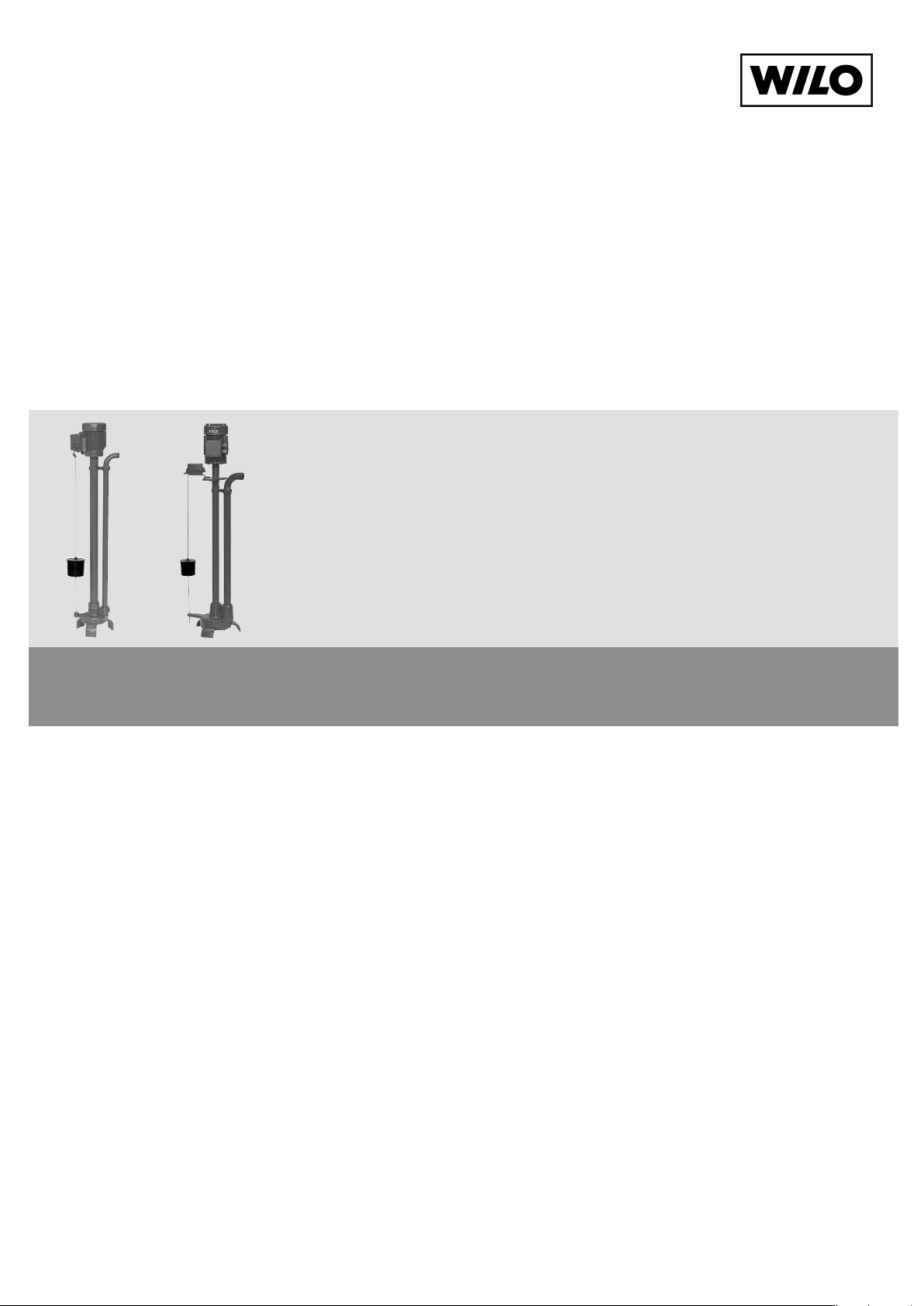
VC 32: switch on motor terminal box (Fig. 1, pos. 1)
VC 40: separately mounted switch box (Fig. 2, pos. 1)
4.2 Products delivered
– VC pump complete with built-in float switch
– Installation and operating instructions
4.3 Accessories
Accessories must be ordered separately.
– Non-return valve
– Shut-off fittings
– Pipe screws
– Flange / counter flange
5 Assembly / Installation
5.1 Assembly (Fig. 1, 2)
Place the pump complete with built-in float switch upright in a
shaft or other container on a flat, fixed surface.
– Maximum shaft depth 950 mm, motor and switching applian-
ce must not be flooded. Minimum shaft dimensions 450 x
450 mm.
– The pump must be installed in a frost-free place.
– The shaft must be free from coarse solids (e.g. building rub-
ble) prior to installation and commissioning.
– The float switch must be free to move unhindered.
– Fixing the float switch connecting rod (Fig. 3):
– Place the indented end of the float rod into the hole provi-
ded on the switching lever horizontally (A) then move
down to a vertical position (B).
– Pull the switching lever and float rod up to the highest
switch setting and gently bend the lower end of the rod
into the hole provided in the pump housing.
To set the pump switch-on and switch-off points, adjust the
fixing screws on the float stops.
– The VC 40 pump can be fixed into 2 horizontal shaft covering
halves (Fig. 2, pos. 2) using a fixing flange (Fig. 4).
– Always ensure that the connection cable
does not become damaged when lowering
the pump into the shaft.
– Do not use the cable to lower the pump!
– Vertical position only.
– For outdoor assembly, all piping, valves,
electronic controls, etc. must be suitably
protected from frost and all other damage.
5.2 Hydraulic connections
– Switch the electricity supply off before connecting the pres-
sure pipe to the pump.
– Diameter of the pressure pipe connection VC 32: 1"
VC 40: 1|"
– Connect the pump ensuring that
– the weight of the pump is not bearing down on the pressu-
re pipe connection
– the load of the pressure pipe does not act on the connec-
ting sleeve.
– The customer must ensure the pipe weights are supported.
5.3 Electrical connection
The electrical connection should be made by a qualified electrician. Current national regulations must
be observed (e.g. VDE regulations in Germany).
– Ensure all electrical installations comply with the IEC 364
standard and that the mains supply is equipped with a residual current operated circuit-breaker of max. 30 mA.
– Mains fuse 16 A, time-lag
ATTENTION!
– Ensure that the increased starting currents of
1~Motor, 4 to 5 times the nominal motor current, and
3~Motor, 6 to 7 times the nominal motor current,
are drawn off by the mains network.
– The electrical connection must be made before the pump is
lowered into the shaft.
– Check that the mains current and voltage comply with the
data on the rating plate.
– The pump must be earthed in compliance with regulations.
– Assignment of supply terminals (Fig. 5) (Fig. 6) :
Single-phase motor
– VC 32: 1~230 V
Connect the electricity directly to the motor terminal box:
N, L1, PE: connector cables required: 3 x 0.75 mm
2
Factory-assigned: 1 = black, 2,3 = white, 4 = red,
5 = yellow, 6 = blue, 7 = brown, 8 = green
Three-phase motor
– VC 32: 3~230 V
Connect the electricity directly to the motor terminal box:
L1, L2, L3, PE connector cables required: 4 x 0.75 mm
2
– VC 40: 3~400 V
Connect the electricity directly to the motor terminal box:
L1, L2, L3, PE connector cables required: 4 x 1.55 mm
2
– For three-phase motors it is advisable to install a motor
safety switch. Set the nominal motor current in accordance with the rating plate data.
– Direction of rotation (only for three-phase motors)
The correct direction of rotation must be tested before the
pump is submerged. The correct direction of rotation is
indicated by a directional arrow on the motor.
If the direction of rotation is incorrect, 2 of the mains connection phases must be switched.
6 Operation
The pump must never be used to empty a swimming
pool while there are still bathers in the water.
6.1 Filling and ventilating the unit
– The water level may not be reduced below the minimum
immersion depth of the pump housing. The level control
must be set at the minimum level: Fig. 1/2.
– The pump can only be filled and bled when the pump hou-
sing is fully immersed.
– Always ensure the float can move freely.
6.2 Start of pump operation
– Start the pump and ensure that the built-in shut-off fittings
are open.
Do not allow the pump to run dry! The pumping
liquid lubricates the friction bearing.
– The float switch will now automatically ensure correct opera-
tion of the pump.
– Check the current consumption. The current consumption
must comply with the data on the rating plate.
7 Maintenance
Prior to maintenance or repair work, turn off the
pump and ensure that it is not turned on by unauthorised personnel.
This pump requires practically no maintenance at all.
Should the impeller become blocked with solids, proceed as
follows:
– Detach the pump from the pressure pipe connection.
ATTENTION!
7
Page 8

ENGLISH
– Remove the pump from the shaft and rinse it carefully using
clear water before touching it (never underestimate the risk
of infection!).
– Set the pump down, loosen the 3 filter fixing screws, remove
the base and disassemble the cover.
– If possible do not remove the impeller to clean it.
8
8 Problems, Causes and Remedies
Problems Causes Remedies
8.1. Pump does not run a) Electricity supply cut off a) Check wires
If necessary replace fuses.
Switch on the circuit breaker and
mains switch.
b) Winding or cable damaged b) Check cable resistance and if
ecessary replace cable.
Attention: when replacing,
match the phases up exactly
according to colour.
c) Rotor blocked (motor buzzing) c) Clean the impeller
(see Chapter 7).
d) Motor defect d) Replace the motor
8.2.Pump works a) Inlet filter blocked a) Remove and clean filter
insufficiently or not at all b) Wrong direction of rotation b) Interchange two of the mains
connection phases
c) Pressure pipe blocked c) Remove and clean piping
d) Impeller blocked by foreign body d) See 8.1-c
e) Shut-off valve on outlet side e) Check shut-off valve and open
closed or not fully open. where necessary
8.3.Pump stops a) Electronic installation fault a) Check entire electronic installation
b) Pump blocked b) See 8.1-c
c) Pump sluggish c) See 8.1-c
If no solution can be found, please contact your plumbing and heating specialist or your nearest WILO customer services
team or representative.
Subject to technical alterations!
Page 9

Page 10

 Loading...