

Page 1
Pioneering for You
Wilo-Control SC-Fire Jockey
de Einbau- und Betriebsanleitung
en Installation and operating instructions
fr Notice de montage et de mise en service
2 541 363-Ed.01 / 2014-02-Wilo
nl Inbouw- en bedieningsvoorschriften
Page 2
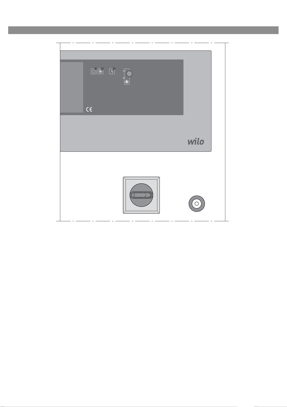
Fig. 1:
0 OFF
I ON
Page 3

English
Installation and operating instructions
1 General
1.1 About this document
The language of the original operating instructions is German. All other languages of these
instructions are translations of the original operating instructions.
These installation and operating instructions are
an integral part of the product. They must be kept
readily available at the place where the product is
installed. Strict adherence to these instructions is
a precondition for the proper use and correct
operation of the product.
These installation and operating instructions correspond to the relevant version of the product and
the underlying safety regulations and standards
valid at the time of going to print.
EC declaration of conformity:
A copy of the EC declaration of conformity is a
component of these operating instructions.
If a technical modification is made on the designs
amed there without our agreement or the decla-
n
rations made in the installation and
instructions on product/personnel safety are not
observed, this declaration loses its validity.
operating
2Safety
These operating instructions contain basic information which must be adhered to during installation, operation and maintenance. For this reason,
these operating instructions must, without fail, be
read by the service technician and the responsible
specialist/operator before installation and commissioning.
It is not only the general safety instructions listed
under the main point “safety” that must be
adhered to but also the special safety instructions
with danger symbols included under the following
main points.
2.1 Indication of instructions in the operating
instructi
Symbols:
General danger symbol
Danger due to electrical voltage
NOTE
Signal words:
DANGER!
Acutely dangerous situation.
Non-observance results in death or the most
serious of injuries.
WARNING!
The user can suffer (serious) injuries. “Warning”
implies that (serious) injury to persons is probable if this information is disregarded.
ons
CAUTION!
There is a risk of damaging the
“Caution” implies that damage to the product is
likely if this information is disregarded.
NOTE:
Useful information on handling the product. It
draws attention to possible problems.
Information that appears directly on the product,
such as:
• Direction of rotation arrow,
• Identification for connections,
• Rating plate,
• Warning sticker,
must be strictly complied with and kept in legible
condition.
2.2 Personnel qualifications
The installation, operating and maintenance personnel must have the appropriate qualifications
this work. Area of responsibility, terms of ref-
for
erence and monitoring of the personnel are to be
e
nsured by the operator. If the personnel are not in
possession of the necessary knowledge, they are
to be trained and instructed. This can be accomplished if necessary by the manufacturer of the
product at the request of the operator.
2.3 Danger in the event of non-observance of the
safety instructions
Non-observance of the safety instructions can
result in risk of injury to persons and damage to
the environment and the product/unit. Nonobservance of the safety instructions results in
the loss of any claims to damages.
In detail, non-observance can, for example, result
in the following risks:
• Danger to persons from electrical, mechanical and
bacteriological influences
• Damage to the environment due to leakage of
hazardous materials
• Property damage
• Failure of important produc
• Failure of required maintenanc
dures
2.4 Safety consciousness on the job
The safety instructions included in these installation and operating instructions, the existing
national regulations for accident prevention
together with any internal working, operating and
safety regulations of the operator are to be complied with.
2.5 Safety instructions for the operator
This appliance is not intended for use by persons
(including children) with reduced physical, sensory
or mental capabilities, or lack of experience and
knowledge, unless they have been given supervision or instruction concerning use o
by a person responsible for their safety.
Children should be supervised to ens
do not play with the appliance.
pump/unit.
t/unit functions
e and repair proce-
f the appliance
ure that they
Installation and operating instructions Wilo-Control SC-Fire Jockey 9
Page 4

English
• If hot or cold components on the product/the unit
lead to hazards, local measures must be taken to
guard them against touching.
• Guards protecting against touching moving components (such as the coupling) must not be
removed whilst the product is in operation.
• Leakages (e.g. from the shaft seals) of hazardous
fluids (which are explosive, toxic or hot) must be
led away so that no danger to persons or to the
environment arises. National statutory provisions
are to be complied with.
• Highly flammable materials are always to be kept
at a safe distance from the product.
• Danger from electrical current must be eliminated.
Local directives or general directives [e.g. IEC, VDE
etc.] and instructions from local energy supply
companies must be adhered to.
2.6 Safety instructions for installation and
maintenance work
The operator must ensure that all installa
maintenance work is carried out by authorised and
qualified personnel, who are sufficiently informed
from their own detailed study of the operating
instructions.
Wo rk on the produ ct/u nit must onl y be c arr ied out
when at a standstill. It is mandatory that the procedure described in the installation and operating
instructions for shutting down the product/unit
be complied with.
Immediately on conclusion of the work, all safety
and protective devices must be put back in position and/or recommissioned.
2.7 Unauthorised modification and manufacture of
spare parts
Unauthorised modification and manufacture of
spare parts will impair the safety of the product/
personnel and will make void the manufacturer's
declarations regarding safety.
Modifications to the product are only permissible
after consultation with the manufacturer. Original
spare parts and accessories authorised by the
manufacturer ensure safety. The use of other
parts will absolve us of liability for consequential
events.
tion and
2.8 Improper use
The operating safety of the supplied product is
nly guaranteed for conventional use in accord-
o
ance with Section 4 of the operating instructions.
The limit values must on no account fall under or
exceed those specified in the catalogue/data
sheet.
3 Transport and interim storage
Immediately after receiving the product:
• Check product for transport damage.
• In the event of damage in transit, take the necessary steps with the forwarding agent within the
respective time limits.
CAUTION! Risk of property damage!
Incorrect transport and interim storage can
cause property damage.
• The switchgear is to be protected against moisture and mechanical damage.
• It must not be exposed to temperatures outside
the range
of -10°C to +50°C.
4 Application (intended use)
The Fire Jockey pump switchgear is used to control a pressure-maintaining (jockey) pump in
automatic sprinkler systems, in accordance with
EN 12845.
The device is used in residential and office buildings, hospitals, hotels, administrative and industrial buildings.
The pump is used in conjunction with suitable signal transmitters and it is switched on and off
according to the pressure.
The intended use includes complying with these
instructions.
Any other use is considered to be outside the
intended use.
10 WILO SE 07/2012
Page 5

5Product information
5.1 Type key
Example: W-CTRL-F-1x1.25-T4-DOL-FM-ND5-J
W
CTRL Control
F F = fire fighting purposes
1x Number of pumps
1.25A Maximum rated motor current [A]
T4 T = 3 phases; 4 = 400 V
DOL Direct online (direct starting)
FM Frame mounted (on a base frame)
ND5 New Design switchgear measuring
300x500x250mm
J Jockey pump switchgear
5.2 Technical data (standard version)
Mains supply voltage [V]: 3~400 V (L1, L2, L3, PE)
Frequency [Hz]: 50/60 Hz
Control voltage [V]: 24 VAC
Max. current consumption [A]: See rating plate
Protection class: IP 54
Max. fuse protection on mains side [A]: See wiring diagram
Ambient temperature [°C]: 0 to +40°C
Electrical safety: Degree of contamination II
Alarm/signalling contact 250 VAC, 1 A
W = WILO
English
5.3 Scope of delivery
•Switchgear
•Wiring diagram
• Installation and operating instructions for Fire
Jockey pump
• Test report in accordance with EN 60204-1
5.4 Accessories
6 Description and function
6.1 Description of the product
6.1.1 Function description
The switchgear is used to cont
maintaining (jockey) pump in sprinkler systems, in
accordance with EN 12845. The pump can be
switched on and off by the control depending on
the pressure. The system's operating statuses
(e.g. standby, pump operation and fault) are displayed visually by LEDs on the door. In addition,
th
e operating mode can be changed using a rotary
switch.
A potential-free contact is available for forwarding a fault signal to the building management system.
rol a pressure-
6.1.2 Switchgear set-up
The set-up of the switchgear depends on the
capacity of the pump to be connected. It consists
of the following main components:
• Main switch: for switching the switchgear on/off
• Human-machine interface (HMI): signal lamp for
displaying the operating status (standby, pump
operation and fault), rotary switch for selecting
the operating mode
• Fuse protection for drives: fusing for the pump
motor by means of a motor protection switch
• Contactors/contactor combinations: contactors
for switching on the pumps
• Manual/auto rotary switch: switch for selecting
“manual” operating mode (pump switched on
manually) and “auto” (pump switched on depending on pressure)
6.2 Function and operation
DANGER! Risk of fatal injury!
When working on the open switchgear, there's a
danger of electric shock from touching the live
components.
This work must only be carried out by qualified
personnel!
NOTE:
After connecting the switchg
voltage, as well as after every mains interruption,
the switchgear returns to the operating mode set
before the power interruption.
ear to the supply
Installation and operating instructions Wilo-Control SC-Fire Jockey 11
Page 6

English
6.2.1 Switchgear operating modes (Fig. 1)
Switching the switchgear on/off
After connection to the mains supply, the switchgear can be switched on or off using the main
switch. Once the main switch has been switched
on, the system is instantly ready for operation.
Operational readiness is displayed by the signal
lamp lighting up green.
Pump request
If the pressure falls below the target pressure on
the pressure switch, the connected pump is
switched on. The signal lamp indicates th at
the pump is operating.
Once the target pressure is reached or exceeded,
the pump immediately switches off. The signal
lamp
6.2.2 Motor protection
Excess current protection
Direct-starting motors are protected by motor
protection switches with thermal and electromagnetic trip triggers. The trigger current must be
set directly on the motor protection switch.
The motor protection is also active in manual
mode, and leads to deactivation of the corresponding pump.
6.2.3 Operation of the switchgear
Main switch
On/off (lockable in “off” position)
goes out.
6.2.4 Switchgear display elements
Operational standby
The “operational standby” signal lamp lights up
green when the system has a power supply and is
switched on via the main switch. The system is
ready for operation.
Pump operation
The “pump operation” signal lamp lights up green
when the pump is switched on and there are no
faults.
Fault
The “fault” signal lamp lights up yellow when the
motor protection switch has been tripped by
excess current in the pump.
7 Installation and electrical connection
Installation and electrical connection must be
carried out in accordance with local regulations
and only by qualified personnel!
WARNING! Risk of injury!
The existing directives for accident prevention
must be adhered to.
Warning! Danger of electric shock!
Danger from electrical current must be eliminated.
Local directives or general directives [e.g. IEC]
and instructions from local energy supply companies must be adhered to.
7.1 Installation
Install the switchgear/system at a dry location.
Manual/auto rotary switch
The rotary switch has two switch positions. In the
upper position, the system is in “auto” operating
mode. In the lower position, the system is in
“manual” operating mode.
“Auto” operating mode:
If the rotary switch is set to “auto” (upper position), the pump is controlled according to the
pressure switch or the pressure.
“Manual” operating mode:
If the rotary switch is set to “manual” (lower position), the pump is switched on immediately,
regardless of the pressure switch or pressure. The
pump remains continuously switched on for as
long as the rotary switch is set to “manual”.
12 WILO SE 07/2012
Protect the place of installation from
sure to sunlight.
7.2 Electrical connection
DANGER! Risk of fatal injury!
Improper electrical connections can lead to fatal
electric shocks.
• Have the electrical connection established by an
electrician approved by the local electricity supplier only and in accordance with local regulations.
• Observe the installation and operating instructions for the pumps and accessories.
• Disconnect the power supply before any work.
Warning! Danger of electric shock!
There is a potentially fatal voltage on t
side, even when the main switch is turned off.
direct expo-
he supply
Page 7

English
• The type of mains, current and voltage of the
mains connection must match the details on the
rating plate of the control device.
NOTE:
• Fuse on mains side in accordance with the information in the wiring diagram
• Feed the ends of the mains cable through the
threaded cable connections and cable inlets and
wire them according to the markings on the terminal strips.
• Earth the pump/installation in accordance with
the regulations.
7.2.1 Power supply connection
Connect the on-site 4-wire cable (L1, L2, L3, PE)
for the supplying network to the main switch, in
accordance with the circuit diagram.
7.2.2 Pump connection
Observe the installation and operating instructions for the pumps!
The pump is connected to the terminal strips as
per the circuit diagram. The pump is operated via
direct starting.
7.2.3 Pressure switch connection
The pressure switch is connected to the terminal
strips as per the circuit diagram. The pressure
switch contact closes when there is a pressure
drop and switches on the pump.
7.2.4 Fault signal connection
At the fault signal terminal strip, a signal indicating
a fault can be transferred to a potential-free contact (see circuit diagram).
8 Commissioning
WARNING! Risk of fatal injury!
Commissioning by qualified personnel only!
Improper commissioning
injury. Have commissioning performed by qualified personnel only.
DANGER! Risk of fatal injury!
When working on the open switchgear, there's a
danger o
f electric shock from touching the live
components.
This work must only be carried out by qualified
personne
l!
poses a risk of fatal
Before switching on for the first time, the on-site
iring must be checked, in particular the earthing.
w
Tighten all connection terminals prior to commissioning!
8.1 Checking the motor direction of rotation
By briefly switching on the pump in “manual”
operating mode (see 6.2.3), check that the direction of rotation of the pump in mains operation is
correct. When the pump motor runs out, compare
the direction of rotation of the fan wheel and the
direction specified on the pump housing.
If the direction of rotation of the pump in mains
operation is wrong, swap over any two phases of
the power cable.
8.2 Setting the excess current protection
In the case of direct starting, the motor protection
switch must be set to rated current I
pump. The rated current I
is specified on the
N
for the
N
pump's rating plate.
9Maintenance
Have maintenance and repair work carried out
by qualified skilled personnel only!
DANGER! Risk of fatal injury!
There is a risk of fatal injury from electric shock
when working on electrical equipment.
• The switchgear should be electrically isolated
and secured against unauthorised switch-on
during any maintenance or repair work.
• Any damage to the connection cable should only
ever be eradicated by a qualified electrician.
• The switchgear must be kept clean.
• Visual inspection of the electric system parts in
the switchgear.
10 Faults, causes and remedies
DANGER! Risk of fatal injury!
There is a risk of fatal injury from ele
when working on electrical equipment.
Have faults remedied by qualified skilled personnel only! Follow the safety instructions in
2 Safety.
Section
Before all work to remedy faults,
unit from the power supply, and make sure it
cannot be switched back on by unauthorised
persons.
ctric shock
disconnect the
It is recommended that yo
u have the switchgear
commissioned by Wilo customer service.
Installation and operating instructions Wilo-Control SC-Fire Jockey 13
Page 8

English
10.1 Fault indication
If a fault occurs, the signal lamp for the fault signal
lights up yellow. The fault signal can be
transferred to the potential-free contact.
Faults Causes Remedy
Excess current protection device
has tripped
Switch the motor protection switch
back on
Signal lamp is lit up yellow
If the fault cannot be remedied, please contact
your nearest Wilo customer service point or
representative.
14 WILO SE 07/2012
Page 9

Page 10

Pioneering for You
WILO SE
Nortkirchenstraße 100
D-44263 Dortmund
Germany
T +49(0)231 4102-0
F +49(0)231 4102-7363
wilo@wilo.com
www.wilo.com
 Loading...