

Page 1
Pioneering for You
Wilo-Control SC-Fire Electric A2P
en Installation and operating instructions
4 206 383-Ed.01 / 2017-01-Wilo
Page 2
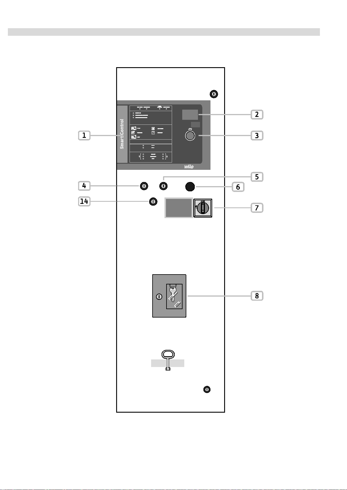
Fig. 1
English
WILO SE 01/2017 2
Page 3
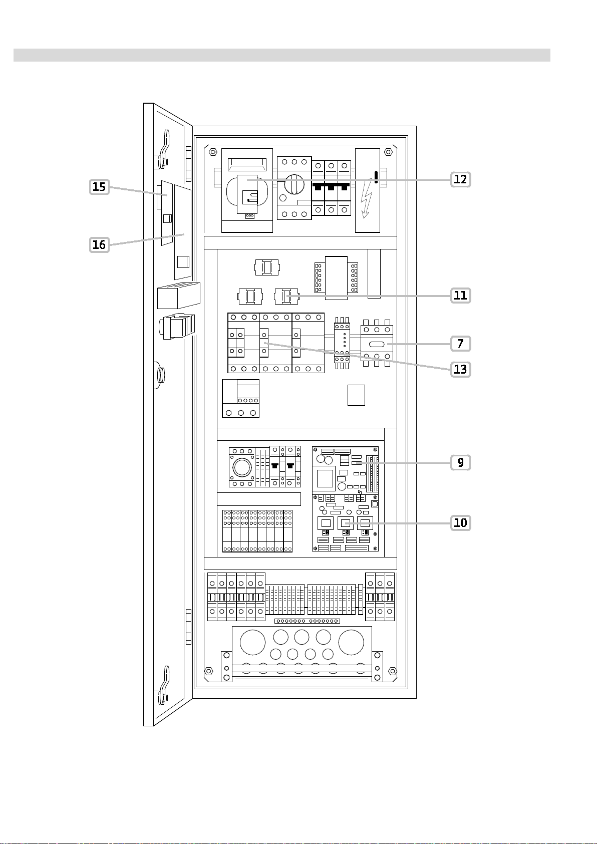
Fig. 1
English
Installation and operating instructions Wilo-SC-Fire Electric A2P 3
Page 4

Fig. 2
English
WILO SE 01/2017 4
Page 5
English
1 General
About this document
The language of the original installation and operating instructions is German. All other lan guages of these
instructions are translations of the original installation and operating instructions.
The installation and operating instructions are an integral part of the product. They must be kept close to the
product and be ready for use if necessary. Strict adherence to these instructions is a precondition for the
proper use and correct operation of the product.
These installation and operating instructions correspond to the relevant version of the product and the
underlying safety standards valid at the time of going to print.
EC declaration of conformity: A copy of the EC declaration of conformity is a key component of these installation and operating instructions. If a technical modification is made on the designs listed therein without prior approval or the declarations made
in the installation and operating instructions on product/personnel safety are not observed, this declaration
loses its validity.
2 Safety
These installation and operating instructions contain important information which must be adhered to during
installation, operation and maintenance. For this reason, these instructions must, without fail, be read by the
service technician and the responsible specialist/operator before installation and commissioning.
It is not only the general safety instructions listed under the main point “safety” that must be adhered to but also
the special safety instructions with danger symbols included under the following main points.
2.1 Symbols and signal words used in the installation and operating instructions
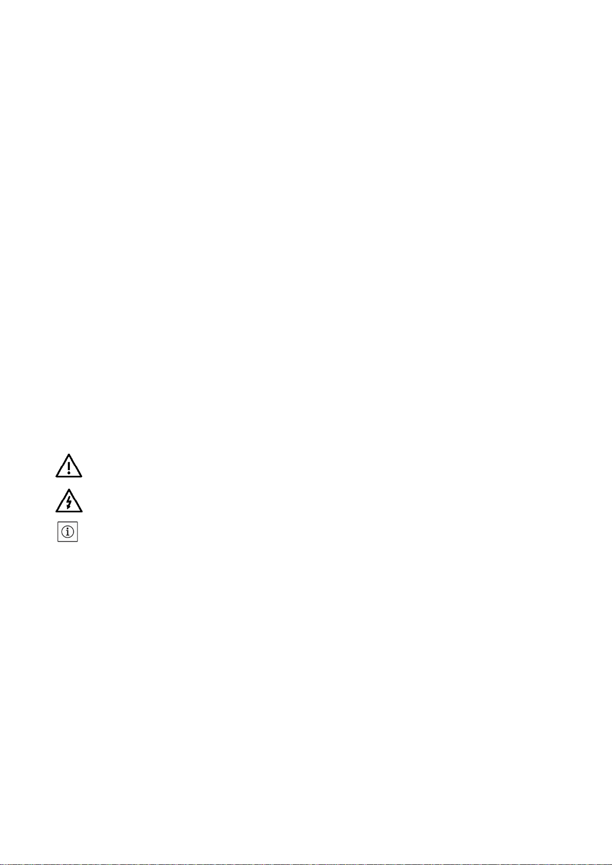
Symbols:
HELPFUL NOTE
Signal words:
DANGER!
Acutely dangerous situation.
Non-observance results in death or the most serious of injuries.
WARNING!
The user may suffer (serious) injuries. “Warning” implies that (serious) injury to persons is
probable if this information is disregarded.
CAUTION!
There is a risk of damaging the pump/system. “Caution” implies that damage to the product is
likely if this information is disregarded.
General danger symbol
Danger due to electrical voltage
Installation and operating instructions Wilo-SC-Fire Electric A2P 5
Page 6

English
NOTE:
Useful information on handling the product. It draws attention to possible problems.
2.2 Personnel qualifications
The installation, operating and maintenance personnel must have the appropriate qualifications for this work.
Area of responsibility, terms of reference and monitoring of the personnel are to be ensured by the operator.
If the personnel are not in possession of the necessary knowledge, they are to be trained and instructed.
This can be accomplished if necessary by the manufacturer of the product at the request of the operator.
2.3 Danger in the event of non-observance of the safety instructions
Non-observance of the safety instructions can result in risk of injury to persons and damage to the
environment and the product/unit. It also results in the loss of any claims to damages.
In detail, non-observance can, for example, result in the following risks:
• Danger to persons due to electrical, mechanical and bacteriological influences.
• Damage to the environment due to leakage of hazardous materials.
• Property damage.
• Failure of important product/unit functions.
• Failure of required maintenance and repair procedures.
2.4 Safety instructions for the operator
This device is not intended for use by persons (including children) with reduced physical, sensory or mental
capabilities, or lack of experience and knowledge, unless they have been given supervision or instruction
concerning use of the appliance by a person responsible for their safety.
Children should be supervised to ensure that they do not play with the device.
• If the product/unit poses a threat due to components being too hot or too cold, these components must
be protected by the customer against touching.
• Guards which protect personnel from coming into contact with moving components (e.g. the coupling)
must not be removed while the product is in operation.
• Hazardous fluids (e.g. from the shaft seals) which have leaked (which are explosive, toxic or hot) must
be eliminated so that no danger to persons or to the environment arises. National statutory provisions
are to be complied with.
• Highly flammable materials are always to be kept at a safe distance from the product.
• Danger from electrical current must be eliminated. Local directives or general directives
[e.g. IEC, VDE etc.] and instructions from energy supply companies must be adhered to.
2.5 Safety instructions for installation and inspection work
The operator must ensure that all maintenance and installation work is carried out by authorised and qualified
personnel, who are sufficiently informed based on their own detailed study of the installation and operating
instructions.
Work on the product/unit must only be carried out when at a standstill. It is mandatory that the procedure
described in the installation and operating instructions for shutting down the product/unit be complied with.
Immediately on conclusion of the work, all safety and protective devices must be put back in position and/or
recommissioned.
WILO SE 01/2017 6
Page 7

English
2.6 Unauthorised modification and manufacture of spare parts
Unauthorised modification and manufacture of spare parts will impair the safety of the product/personnel and
will make void the manufacturer's declarations regarding safety.
Product modifications are exclusively authorised following the agreement of the manufacturer. Original spare
parts and accessories authorised by the manufacturer ensure safety. The use of other parts will absolve the
company of liability.
2.7 Improper use
The operating safety of the supplied product is only guaranteed for conventional use in accordance with
Section 4 of the installation and operating instructions. The limit values must on no account fall under or
exceed those values specified in the catalogue/data sheet.
3 Transport and interim stora ge
Upon receipt of the product:
• Check for any damage that may have occurred during transit.
• In the event of damage in transit take the necessary steps within the period defined by the transport
company within the time constraints.
CAUTION! Risk of property damage!
Non-compliant transport and interim storage may cause material damage to the
product.
• The switchgear must be protected against humidity and any mechanical damage.
• The product must not be exposed to temperatures lower than -10 °C and higher
than +50 °C.
Installation and operating instructions Wilo-SC-Fire Electric A2P 7
Page 8
Example:
CTRL
Fixed
Operation
SC
Fixed
Smart Control = control unit
F
Fixed
F = application of protection against fire
1x
Fixed
Number of pumps
T4
Fixed
T = three-phase ; 4 = 400 V
BM: Base mounted (mounted on feet)
ND
Fixed
Switchgear type “New Design”
E
Fixed
Switchgear for electric pump
English
4 Applications (application)
The switchgear SC Fire A2P controls a single electric pump in automatic sprinkler systems in accordance with
APSAD (T1-2).
The relevant fields of application are habitable buildings, offices, hospitals, hotels, administrative and
industrial buildings.
The pump is switched according to the pressure or level when it is used with the right signal sensors.
Compliance with this manual is also part of correct use.
Any use which does not meet this criteria is considered to be non-compliant.
5 Product information
5.1 Type key
W-CTRL-SC-F-1x(2)A-T4-(3)-(4)-ND-E
W
Multiple choice
Brand:
W: Wilo
(2) Multiple choice
(3)
(4)
Multiple choice
Multiple choice
Maximum rated current of the motor [A]:
14.1A
20.4A
27.6A
33.7A
39.1A
53.6A
65.8A
78.0A
95.0A
129.0A
On state:
DOL: Direct online (direct starting)
SD: Star Delta (start star-delta)
Type of installation of switchbox:
FM: Frame mounted (placed on a baseplate)
Table 1 – Type key
WILO SE 01/2017 8
Page 9

Technical data
Mains connection voltage [V]:
Frequency [Hz]:
50/60 Hz
230 V AC ; 24 V AC/DC
Absorbed current max [A]:
See the rating plate
Protection class:
IP44
Fuse protection max on mains side [A]:
See circuit diagram
Room temperature [°C]:
0 °C to +50 °C
Electrical safety:
Pollution degree II
Alarm/signal contact:
250 V AC, 1 A
English
5.2 Technical data
3~ 400 V (L1, L 2, L3, PE)
Control voltage [V]:
Table 2 – Technical data
5.3 Scope of delivery
• Switchgear
• Circuit diagram
• Installation and operating instructions
• Check log in accordance with EN 60204-1
5.4 Accessories
6 Description and function
6.1 Product description
6.1.1 Function description
The switchgear is used to control a single electric pump in “sprinkler systems” in accordance with APSAD (T1-2).
In automatic mode the pump is switched on according to the unit pressure. Each pump has 2 pressure switches
at its pressure connection to monitor the pressure. Each pressure switch is controlled by a key switch.
When the pump is started, it can only be switched off manually and only when the pressure has been reached in
the unit.
In manual mode the start of the pump is activated from the HMI.
The st art-up of the pump is done by means of a start-up tank, the filling of which is controlled by a float switch.
States of system operation such as availability, pump operation, malfunctions, etc. are visually indicated by
LEDs on the front of the switchbox and equally by a buzzer. Operating parameters such as current or voltage
values are displayed on the screen. The operation is performed by means of the rotary knob, key switches and
buttons accessible on the front of the switchbox.
Potential-free contacts are available for transmitting the collective run or malfunction signals to a possible
BMS (building management system).
Installation and operating instructions Wilo-SC-Fire Electric A2P 9
Page 10
English
6.1.2 Structure of the switchgear (Fig. 1) The installation of components in the switchbox depends on the performance of the pump connected.
The switchgear includes the following main components:
• Main on/off switch: Power supply of the switchgear (pos. 7)
• Human-machine interface (HMI): signal lamps or screen for displaying the state of operation (for example
availability, malfunction and rated current of the pump), user test of the pump and function allowing error
messages to be acknowledged (pos. 1, 2, 3)
• Key switch: selection of operating mode (manual, deactivation, automatic) of the pressure switches
(pos. 4, 5)
• Change-over switch (pos. 14): access to level 2
• Buzzer signal: additional buzzer for certain error messages (pos. 6)
• “SC controller” PCB: printed circuit board with microcontroller (pos. 9)
Warni ng: There are 2 “SC controller” PCBs, fixed with spacer sleeves to superimpose them.
• “SC U/I” PCB: Measurement/acquisition voltage/current (pos. 10)
• Current converter: pump current measurement (pos. 11)
• Fuse protection: protection of the pump motor (pos. 12)
• Contactor: Contactor of the motor of the pump (pos. 13)
• “SC Display” PCB: printed circuit board with display and rotary button (pos. 14)
• “SC I/O” PCB: printed circuit board with control/operating console (pos. 15)
• Key box: enables the storage of the keys from the key switches (pos. 8)
6.2 Function and operation
DANGER! Risk of death!
When working on an open switchgear, there is a risk of electrocution in the event of
contact with active conductors.
This work must only be carried out by qualified personnel!
After connecting the switchgear to the connection voltage as well as after each network cut-off, the
switchgear reverts to the operating mode set before the voltage cut-off.
6.2.1 Switchgear operating modes of the start/deactivation After connection to the power supply, the switchgear can be switched on or off using the main switch.
Once the main switch has been activated, the system is instantly ready for operation. After several seconds,
the green signal lamp (Fig. 2, pos. 1) lights up.
WILO SE 01/2017 10
Page 11
Key switch 1
AUTO
OFF
MANUAL
Float switch
Float switch
Float switch
Float switch
-
Float switch
English
Operating mode You can define the operating mode of the switchgear by selecting one of the three positions of the key
switch “Auto”, “0” or “Manual”.
Starting the
motor with...
Table 3: Operating modes
Automatic mode
The key switch (Fig. 1, pos. 4, 5) is placed in the “Auto” position, the “Auto” position is thus confirmed by the
corresponding green LEDs (Fig. 2, pos. 15, 16) .
The unit starts up automatically once the pressure switch no. 1 opens and the key switch no. 1 is in the “Auto”
position or once the pressure switch no. 2 activates and the key switch no. 2 is in the “Auto” position.
Any open pressure switch is signalled by a green LED for pressure switch 1 or a yellow LED for the pressure
switch 2 (Fig. 2, pos. 19, 20). Triggering of the float switch (low level of start-up tank) st arts the pump if at least
one of the 2 key switches is in the “Auto” position.
Non-automatic mode
This mode is activated when the key switches are not in the “Auto” position.
This operating mode is signalled by the red LEDs (Fig. 2, pos. 17, 18).
Furthermore, the output “NON-AUTO MODE 1/2” is activated.
Manual mode To perform a manual start-up, place one of the key switches in the “Man” position. The manual start button “ON”
(Fig. 2, pos. 8) enables start-up of th e pump. Deactivation mode
To switch off the pump, at least one of the key switches must be in the “0” position.
As soon as the pressure switch or the float switch is no longer activated, the pump can be switched off by
means of the “OFF” button (Fig. 2, pos. 12).
Key
switch 2
AUTO
OFF
MANUAL
Pressure switch 1
Pressure switch 2
Pressure switch 1
Pressure switch 1
“ON” button
Pressure switch 2
“ON” button
“ON” button
Pressure switch 2
“ON” button
“ON” button
Pump start-up In auto mode, if the pressure measured by at least one of the two pressure switches is below the switch-on
threshold, the LED/LEDs (“active” Fig. 2, pos. 19 and pos. 20) turn/s on green for pressure switch 1 or yellow
for pressure switch 2. Once the follow-up time has elapsed (see menu 1.2.5.1) the pump starts.
Note: If the follow-up time (menu 1.2.5.1) is quite long, it is possible to see the LED flashing while the follow-up
time elapses.
The LED (“on” Fig. 2, pos. 13) turns on green and signals the operation of the pump. Throughout pump
operation, the instantaneous current of the pump is monitored and displayed on the screen. When a malfunction
arises, and even if the pump continues to function, the error code of the malfunction is displayed for
30 seconds.
Installation and operating instructions Wilo-SC-Fire Electric A2P 11
Page 12

English
Once the set pressure is reached or exceeded it is possible to switch off the LED/LEDs (“active” Fig. 2,
pos. 19 and pos. 20) previously turned on by pressing the malfunction acknowledgement. The pump is
still running and must be switched off manually.
Start-up tank
If the level of water in the start-up tank of the pump is less than 2/3 of the full level, the float switch closes and the
red indicator light is activated (Fig. 2, pos. 6). Following a configurable follow-up time (see menu 1.2.5.2) the
pump switches on and the green indicator light (Fig. 2, pos. 13) is activated.
Note: As the follow-up time expires, the indicator light flashes
As soon as the tank is full, the float switch opens and the error message can be acknowledged. The indicator light
turns off (Fig. 2, pos. 6) and the pump can be switched off manually. The audible warning (Fig. 2, pos. 13)
deactivates also.
Control of the voltage
To increase operational safety, the power supply voltage of the switchbox is subject to permanent control.
The power supply voltage is configured in the menu 1.2.1.1 (400 V by default), the 3 phases are controlled.
When the pump is on standby, the 3 phase-to-phase voltages are displayed one after another.
As soon as the power supply voltage is lower or higher than the defined tolerance level (see menus 5.4.1.0
and 5.4.2.0), an error code is displayed after a certain time lag (see menu 1.2.5.3).
When the pump is in operation, and in case of a malfunction, the pump continues to function.
Protection against excess currents
During pump functioning, the current is subject to permanent monitoring.
The rated current motor is configurable in the menu 1.2.1.2.
The current is monitored over the three phases. When the pump is functioning, the current is indicated on the
screen. The green indicator light (“on” Fig. 2, pos. 13) turns on as soon as the current of the pump reaches a
predefined minimum level (see menu 5.4.3.0).
As soon as the current of the pump exceeds the maximum threshold (see menu 5.4.4.0), the red indicator light
(“malfunction” see menu 1.2.5.5) (Fig. 2, pos. 14) turns on.
Despite the presence of an error, this does not prevent the pump from starting or continuing to function. As soon
as the current level of the pump returns to within the range of the levels permitted, you can acknowledge the
error. And the indicator light (Fig. 2, pos. 14) deactivates.
Monitoring of the “pump in demand”
As soon as the pump switches on, a pressure switch located at the pressure connection monitors whether the
pressure at the pump outlet is correct.
After a certain predefined time (see menu 1.2.2.2), if the pressure at the pump outlet is not reached, the red
indicator light turns on (“pump in demand” Fig. 2, pos. 3).
When the pressure exceeds the configured threshold, the error message can be acknowledged and the indicator
light will change to green (Fig. 2, pos. 3).
Monitoring of failed start-up
When the pump is in operation, and after a certain predefined time in the menu 1.2.2.1, the electrical power
consumption is monitored.
The power is monitored against the following parameterisation: 1.2.1.1 and 1.2.1.2.
During the monitoring period, and after a certain configured lag time (see menu 1.2.5.6), if the minimum value has
not been reached (see menu 5.4.5.0), the indicator light will turn yellow (Fig. 2, pos. 2).
When the power consumed is reached again, the error message can be acknowledged. And the indicator light will
change from yellow to green (Fig. 2, pos. 2).
WILO SE 01/2017 12
Page 13
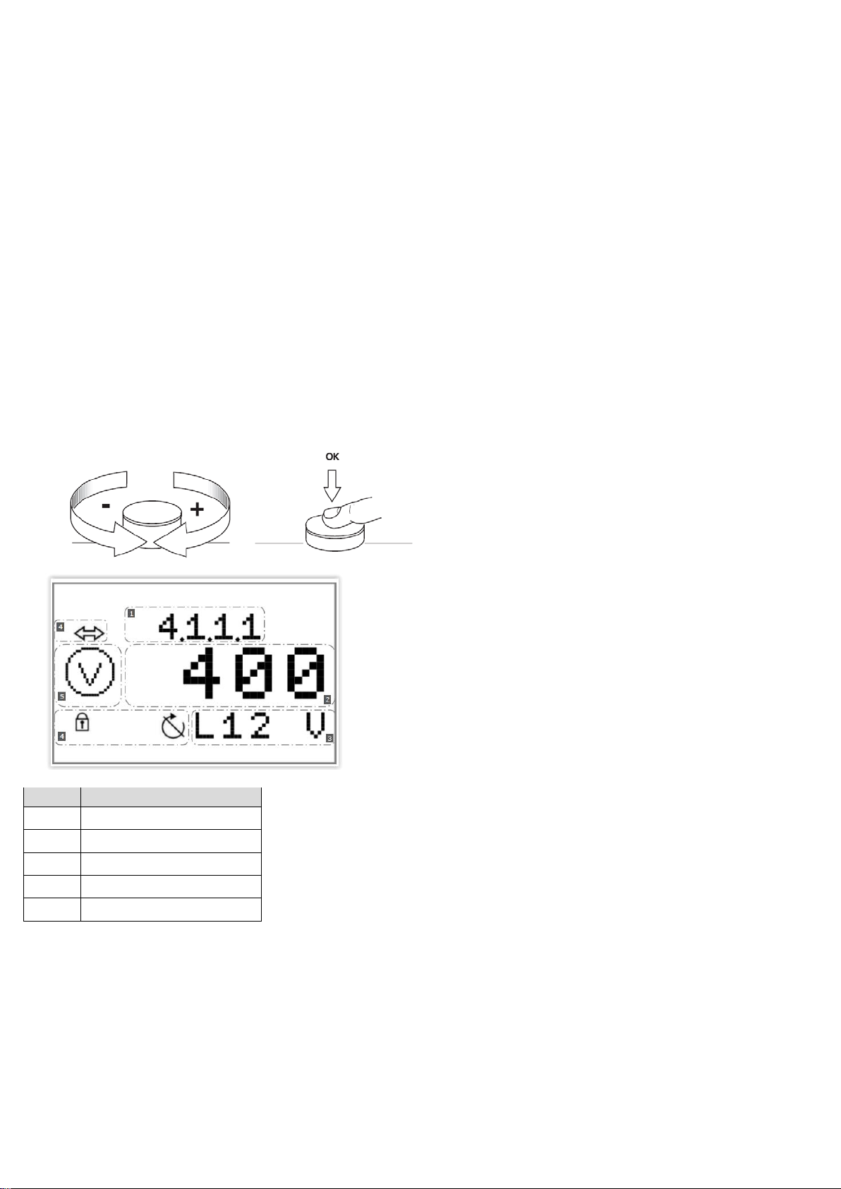
Pos.
Description
1
Menu number
2
Value display
3
Unit display
4
Standard symbols
5
Graphic symbols
English
6.2.2 Application of the switchgear
Operation elements
Levels of access
• The level of access 1 allows access to the function test of the lamp (Fig. 2, pos. 2) without intervention in
addition.
• The level of access 2 is performed using a key switch (Fig. 1, pos. 7) and enables access to the reset
function in the event of error messages (Fig. 2, pos. 4).
• The level of access 3 is performed using a ciphered code encoded in the menu 7.0.0.0, enabling access to all
menu items.
Functions and application elements
• Main switch On/Off (lockable in “Off” position) (Fig. 1, pos. 7)
• LCD screen (Fig. 1, pos. 2) The LCD screen displays the pump operating status and the settings menu.
Thanks to the control button (Fig. 1, pos. 3) you can select the menus and enter the parameters (level 3
access required). To alter the values and scroll through the menu levels, turn the function. To select and
confirm your input, press the button:
Installation and operating instructions Wilo-SC-Fire Electric A2P 13
Page 14
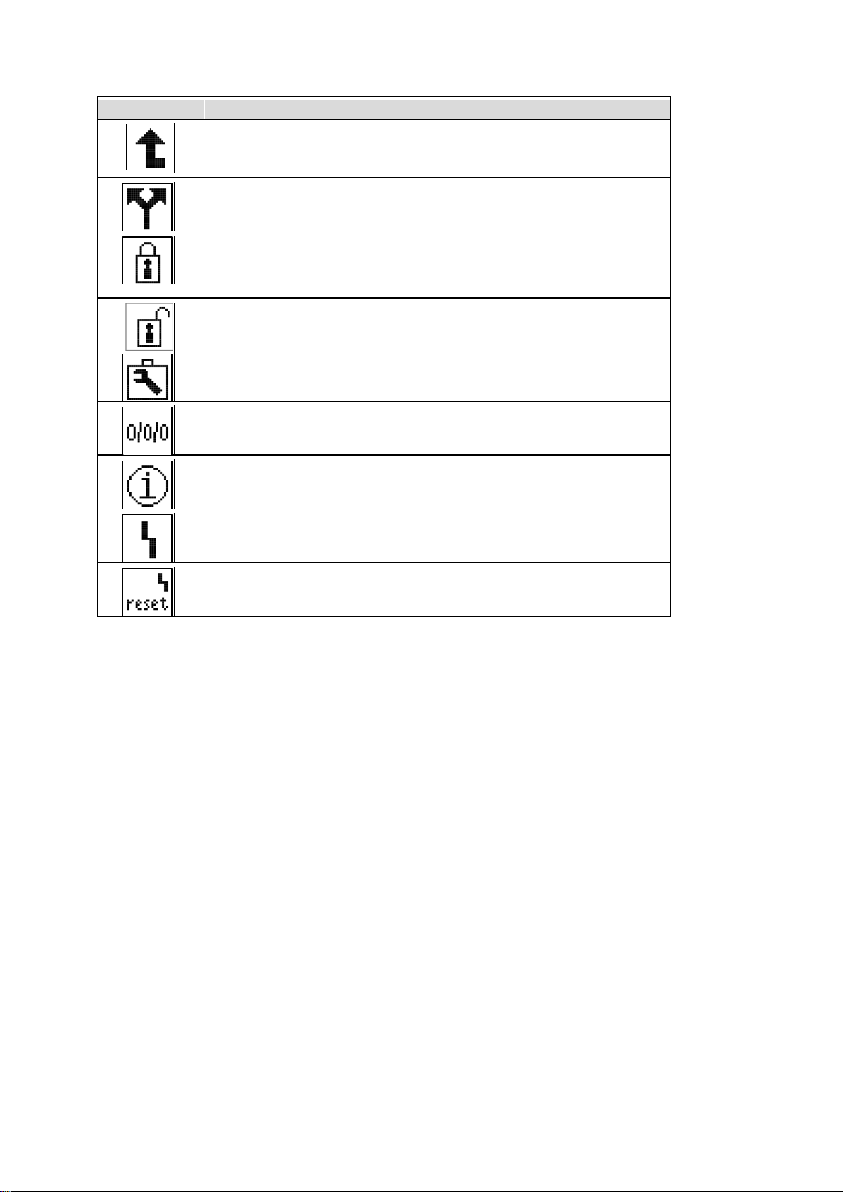
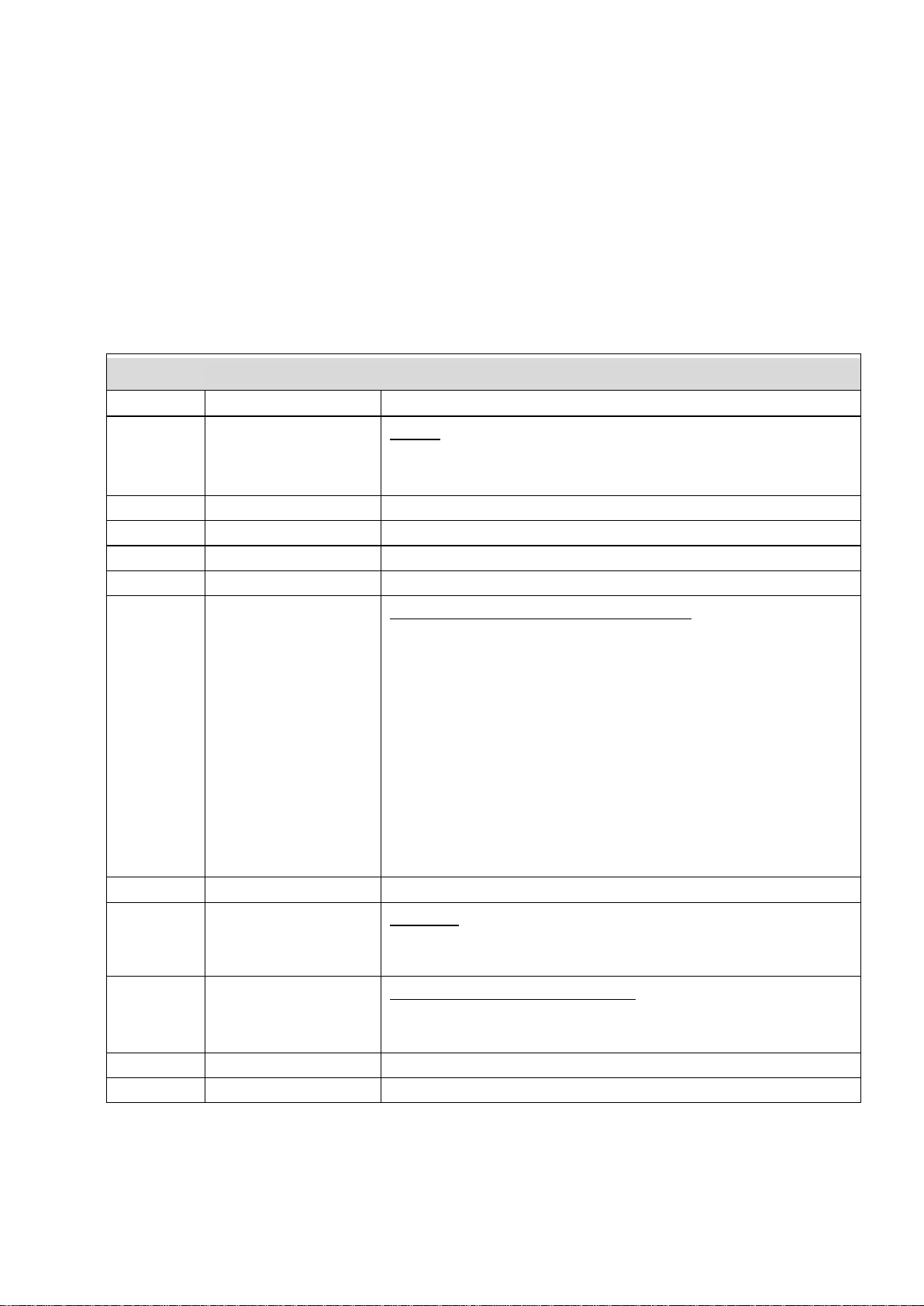
Symbol
Function/description
Brief press: Return to the previous menu
EXPERT menu
1. Notification: service not connected
Unlocked
Service menu
Parameters
Information
Malfunction
Reset malfunction
English
The following graphic symbols are used:
Long press: Return to the main screen
2. Notification: display value – no entry possible
WILO SE 01/2017 14
Page 15
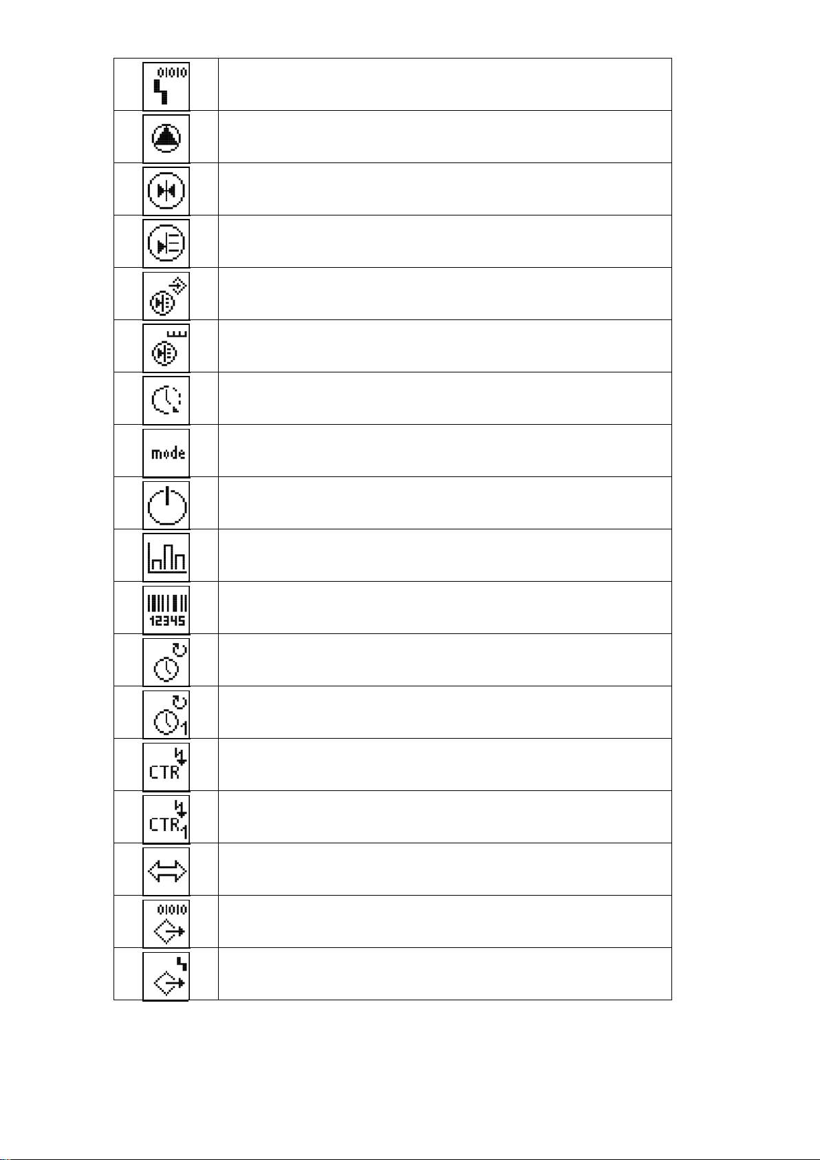
Alarm settings
Pump
Setpoint
Actual value
Sensor signal
Measurement range sensor
Follow-up time
Operating mode/application
Stand-by
Operational data
Switchgear data:
Operating hours
Pump operating hours
Switchgear operating test runs
Pump operating test runs
Communication
Output parameters
SSM parameters
English
Controller type; ID number; software/firmware
Installation and operating instructions Wilo-SC-Fire Electric A2P 15
Page 16
English
Sprinkler (pressure switch)
Pump filling tank (float switch)
Activation failed
Pressure
Power supply (mains)
Voltmeter
Ammeter
Cut-in star-delta
Malfunction signal freely configurable
Malfunction input
WILO SE 01/2017 16
Page 17
English
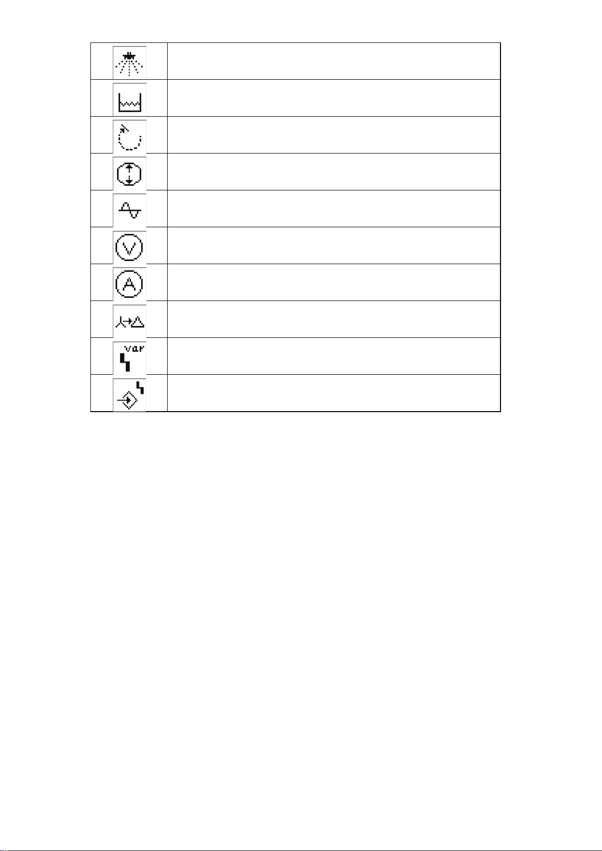
Duration
Power indicator
Communication parameters
Modbus
BACnet
Factory setting
Reset to the factory setting
Alarm counter
Maintenance interval
Reset
Installation and operating instructions Wilo-SC-Fire Electric A2P 17
Page 18
English
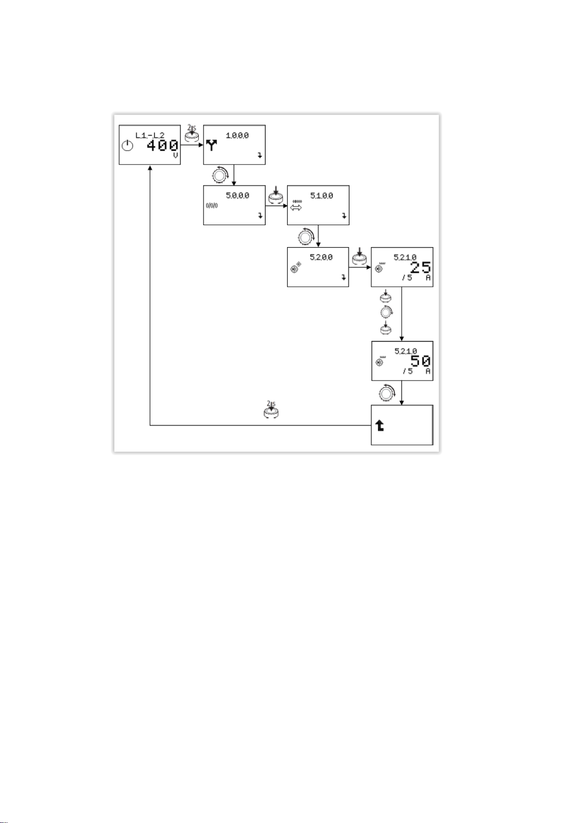
Menu structure: The menu structure of the control system is organised into 4 levels. Navigation in the individual menus as well as the parameter input are described in the example
below – selection of transformers (level 3 required):
WILO SE 01/2017 18
Page 19

Menu accessible from the level of access 1
The main screen indicates the status of the unit.
The display constantly switches from one voltage
“Malfunctions” menu
English
Refer to the following table for a description of the individual menu items.
No.
menu/
1.1.1.1 Screen 1.1.2 Description
to another (alternating between L1-L2, L1-L3 and
L2-L3).
When the pump is in operation, the
instantaneous current on the three phases
and the voltages ar e d is played in turn s on
the screen.
Parameter range
Factory setting
“Services” menu
To access level 3 an access code must be entered.
After 5 minutes of inactivity on HMI or after a main
supply malfunction, access is blocked and the code
must be re-entered.
0…9999
Installation and operating instructions Wilo-SC-Fire Electric A2P 19
Page 20

6.1.0.1
error
7.5.9.9, accessible
The EXPERT menu contains other settings
which enable a detailed configuration of the
English
to
6.1.1.6
Menu accessible from the level of access 3
History memory of m a lfunctions from 1 to 16
Note:
The history memory of malfunctions and the
counter can be reset via menu
on level 3.
Menu unlocked after entering the access
code.
The remaining time [in secon ds ] before
deactivation of the level of acce s s 3 in
case of inactivity on the HMI is also
indicated on the m a in screen.
switchgear.
Access to the parameter menu
enabling modific a tion of the sys tem
operation
Access to the settin gs menu of the
electrical parameters of the pump
WILO SE 01/2017 20
Page 21

English
Adjustment of th e connection voltage 400
Adjustment of the rated cur rent of the pump 0.1..7.8..500.0
Display of the mot or power of the
pump
The parameter menu for all timer
parameters influencing the operation
Adjustment of the follow-up time for the
0..40..120
monitoring of the electrical power of the
pump (electrical error at start-up)
Adjustment of th e follow-up time for th e
0..5..120
monitoring of th e pr es s ure at the pump
outlet (error “pump in demand”)
Installation and operating instructions Wilo-SC-Fire Electric A2P 21
Page 22

English
The settings menu for the follow-up tim es
and delays
Start-up delay of the pump upon
1..120
activation of the pressure switch
Start-up delay upon activation of the
1..120
float switch
Follow-up time of the error message for
0..1..10
the monitoring of the voltage
Follow-up time of the error message
5..10..20
“electrical error a t start-up”
Follow-up time in th e event of error
5..10..20
message through current monitoring
WILO SE 01/2017 22
Page 23

English
No.
menu/
1.1.1.1 Screen 1.1.2 Description
Parameter range
Factory setting
Cut-in time star-delta 0..5..60
Buffer time between the activati on of the
0.00..0.05..1.0
star contactor an d the interlocking of the
delta contactor
Communication
Display of the field bus temporarily
activated
Number bus, Modbus,
BACnet
Pump menu
Display of the au tom a tic mode of operation:
ON or OFF
Installation and operating instructions Wilo-SC-Fire Electric A2P 23
Page 24

English
No.
menu/
1.1.1.1 Screen 1.1.2 Description
Information
Present operation values
Voltage values
Parameter range
Factory setting
Voltage display b etween conductors L 1
and L2
Voltage display b etween conductors L 1
and L3
Voltage display b etween conductors L 2
and L3
WILO SE 01/2017 24
Page 25

English
No.
menu/
1.1.1.1 Screen 1.1.2 Description
Current values
Current display of pump in L1
Current display of pump in L2
Parameter range
Factory setting
Current display of pump in L3
Performance values
Performance display L1
Installation and operating instructions Wilo-SC-Fire Electric A2P 25
Page 26

English
No.
menu/
1.1.1.1 Screen 1.1.2 Description
Performance display L2
Performance display L3
Status informa tion
Parameter range
Factory setting
Display of the status of the
system/availability
Display of the status of the pr e s s ure
switches
Display of the status of the float sw itc h
WILO SE 01/2017 26
Page 27

English
No.
menu/
1.1.1.1 Screen 1.1.2 Description
Operational data
Total hour coun ter of operation of
the switchbox SC-FIRE Electric
Total hour coun ter of operation of the
pump
Parameter range
Factory setting
Total hour coun ter of operation of the
pump since the last start-up
Number counter of power-ups of the
switchbox SC-FIRE electric
Note: Activation of the main switch
Number counter of p ump start-ups
Installation and operating instructions Wilo-SC-Fire Electric A2P 27
Page 28

English
No.
menu/
1.1.1.1 Screen 1.1.2 Description
Unit characteristics
Type of switchbox
Serial number display
Note: Text scrolling
Parameter range
Factory setting
Software version
Firmware version
Adjustments
WILO SE 01/2017 28
Page 29

English
No.
menu/
1.1.1.1 Screen 1.1.2 Description
Communication
Modbus
Baud delivery rate 9.6 19.2 38.4 76.8
Parameter range
Factory setting
Slave address 1..4…247
Parity even not odd
Stop bits 1 2
Installation and operating instructions Wilo-SC-Fire Electric A2P 29
Page 30

English
No.
menu/
1.1.1.1 Screen 1.1.2 Description
BACnet
Baud delivery rate 9.6 19.2 38.4 76.8
Slave address 1...128...255
Parameter range
Factory setting
Parity even not odd
Stop bits 1 2
BACnet Device Instance ID 0...128...9999
WILO SE 01/2017 30
Page 31

English
No.
menu/
1.1.1.1 Screen 1.1.2 Description
Adjustments of the sensors
Selection curr ent transformer 25..1000
Limit values
Parameter range
Factory setting
Lower tolerance limit of the connection
voltage
Higher tolerance l im it of the connec tion
voltage
0..10..20
0..10..20
Installation and operating instructions Wilo-SC-Fire Electric A2P 31
Page 32

Acknowledgemen t b ehaviour for m alfunction
English
No.
menu/
1.1.1.1 Screen 1.1.2 Description
Lower tolerance limit of the rated
current of the pump
Higher tolerance limit of the rated
current of the pump
Adjustment for m inimum performance of
detection of the s tart of the pump
Parameter range
Factory setting
0..10..100
0..10..100
0..50..100
Output parameters
Malfunction s ignal freely configurable
Not store, ON store
messages
WILO SE 01/2017 32
Page 33

English
No.
menu/
1.1.1.1 Screen 1.1.2 Description
Logic reversal sig nal of input Fall, Raise
Activation malfunction messages to
configure
Malfunction a c tive:
Always
or
Only with pump in operation
Parameter range
Factory setting
OFF, ON
Ever, Pump
Response delay 0..60
Malfunction messages
Resetting of malfunction messages
Installation and operating instructions Wilo-SC-Fire Electric A2P 33
Page 34

Access to the para m ete risation of the c a binet
English
6.1.0.1
to
6.1.1.6
Malfunction messages 1 to 16
Service menu
Designation of the cabinet
Adjustment of the serial nu m ber :
Adjustment of th e first 4 numbers of the
serial number
These numbers are adjusted in the factory
and cannot be modified.
Adjustment of the serial nu m ber :
Adjustment of th e last 4 numbers of the
serial number
These numbers are adjusted in the factory
and cannot be modified.
0…9999
0…9999
WILO SE 01/2017 34
Page 35

Alarm menu
Error counter dis play, showing the number of
English
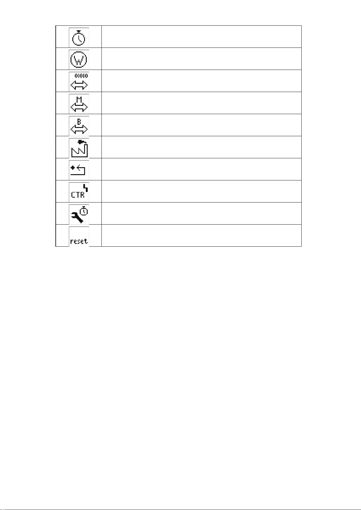
Controller desig nation
Software version display
Factory setting menu:
Possibility to res et the cabinet to factory
configuration
Restoring of factor y parameters:
By pressing the red button, th e s ymbol
“factory” flas hes, turn the red button to the
right, the symbol “reverse a r r ow ” appears,
press the button a s e c ond time to launch the
resetting of the cabinet to fa ctory
configuration.
times that the error E xx.x has occurred.
Scroll through th e er ror codes with th e r ed
button.
Installation and operating instructions Wilo-SC-Fire Electric A2P 35
Page 36

Resetting of the m a lfunction histor y and error
flashes, turn the red button on the r ight side,
The malfunction history and the error c ounter
Operational data of the menu reset
Resetting to zero of the total hour counter of
flashes, then press the button a se c ond time.
English
counter:
By pressing the red button, th e s ymbol
press the button a second time.
are now reset.
Additional menu functions
Activation code:
Enter the activa tion code, for example, to
activate a field bus c onnection.
Modification of a ccess code to level 3:
To reset the access code, please call the
technical service.
pump operation time and start-up number
counter:
By pressing the red button, th e s ymbol
WILO SE 01/2017 36
Page 37

Application menu
Diesel mode display
English
Maintenance and repair menu
Activation/deactivation of th e maintenance
interval
OFF
Or
ON
Adjustment of th e d uration in days for the
maintenance interval
0…92…1000
Resetting to zero of the maintenanc e
message:
By pressing the r ed button, it is possible to
reset the maintena nce countdown .
Installation and operating instructions Wilo-SC-Fire Electric A2P 37
Page 38

Activation/deactivation of th e RIA application:
English
RIA menu
Protected access: To gain access, please call
the technical service.
Activation/deactivation of th e application of
the hydrants:
Once access has been granted by the
technical service.
Adjust the time in minutes for the automatic
stop of the pump
1…20
WILO SE 01/2017 38
Page 39

English
Description of cabinet components:
• Key switches (Fig. 1, pos. 4 and 5)
Pressure switch no. 1 and pressure switch no. 2 each have a key switch.
The 3 positions available are: Auto / Off / Manual.
The keys can only be withdrawn if the key switches are in the “Auto” position. Once the “0” or “Manual”
position has been selected, it is not possible to launch an automatic start-up of the pump, even if the
pressure switch or the float switch are active.
The status corresponding to the “Auto” position is signalled by the green LEDs (Fig. 2, pos. 15, 16) and
that which corresponds to the “0” or “Manual” position by the red LEDs (Fig. 2, pos. 17, 18).
• Key change-over switch (Fig. 1, pos. 14)
Enables access to the functions of level of access 2.
• “ON” (Fig. 2, pos. 8)
By pressing this button, the pump starts manually. To do this, at least one of the two key switches must be
in the “Manual” position. Pump operation is signalled by the green signal lamp (Fig. 2, pos. 13). The pump
must be switched off manually and the signal lamp (Fig. 2, pos. 13) turns off also.
• “BUZZER OFF” (Fig. 2, pos. 9)
This button (level 1) allows an audible signal emitted in case of alarm to be cleared separately. As
soon as a new malfunction arises, the buzzer signal sounds once again.
• “OFF” (Fig. 2, pos. 12)
By pressing this button, the pump switches off manually. To do this, at least one of the two key switches
must be in the “0” position and neither the pressure switch nor the float switch must be activated. The
pump can only be switched off with this button.
• “LAMP TEST” (Fig. 2, pos. 10)
By pressing this button (level 1), all the signal lamps (Fig. 2, pos. 1 to 20) and the buzzer activate and remain
activated while the button is pressed down. This allows for the control of correct operation of all of the LEDs.
Once the button is released, the signal lamps and the alarm buzzer turn off or remain turned on if the
functioning demands it.
• “RESET” (Fig. 2, pos. 11)
By pressing this button (level 2 required), all the error messages/signal lamps are reset insofar as the
cause of the error has been eliminated.
6.2.3 Display elements of the switchgear
“LIVE”
The signal lamp (Fig. 2, pos. 1) turns on green if the power supply is established and if it has been activated
with the main on/off switch.
“ON” The signal lamp (Fig. 2, pos. 13) turns on green if the pump is running and the current consumed by the
pump motor falls within the tolerance limits set (see menu 5.4.3.0).
Installation and operating instructions Wilo-SC-Fire Electric A2P 39
Page 40

English
“START-UP FAILURE” When the pump is running, the power consumed by the pump is permanently monitored. At pump start-up and after a set follow-up time (see menu 1.2.2.1), if the power consumed by the pump is
below the threshold set (see menu 5.4.5.0), the LED (Fig. 2, pos. 2) turns on.
“PUMP IN DEMAND” As soon as the pump is operating and the matching pressure switch does not close after a defined period (see
menu 1.2.2.2), the signal lamp (Fig. 2, pos. 3) lights up red.
“SYSTEM MALFUNCTION” The yellow signal lamp (Fig. 2, pos. 4) signals a software malfunction if the communication between the
control board and the display board is disrupted and the software routine can no longer take place.
“TANK EMPTY” If the water tank level is too low, the LED (Fig. 2, pos. 5) turns on red.
“START-UP TANK LEVEL MALFUNCTION” The signal lamp (Fig. 2, pos. 6) turns on red as soon as the level of the pump start-up tank falls below 2/3 and
when the float switch is triggered. If at least one key switch is in the “Auto” position, the pump starts
automatically. If the level rises sufficiently, the signal lamp (Fig. 2, pos. 6) turns off again. The pump must be
switched off manually.
“LEVEL MINI GLYCOL TANK” If the glycol tank level is too low, the LED (Fig. 2, pos. 7) turns on red. If the malfunction occurs when the pump is in operation the pump continues to function. You can acknowledge the error message and the indicator light (Fig. 2, pos. 7) when the level of the glycol tank
is once again above the low level.
“MALFUNCTION” A signal lamp (Fig. 2, pos. 14) turns on red:
- upon activation of the pump protection device,
- if the thermistor of the motor is triggered,
- if the fuse switch amplifier is open,
- if the fuses have been triggered,
- if a phase sequence malfunction occurs,
- or if a malfunction is detected at the control voltage.
“AUTO MODE” The signal lamp (Fig. 2, pos. 15/16) is turned on green if the matching key switch is in the “Auto” position. In the
automatic mode, the automatic start-up of the pump is possible either via the intermediary of the float switch or
the corresponding pressure switch.
“NON-AUTO MODE” The signal lamp (Fig. 2, pos. 17/18) is turned on red if the matching key switch is in the “0” or “Manual”
position. In the non-automatic mode, no automatic start-up of the pump is possible via the intermediary of the
float switch or the corresponding pressure switch.
WILO SE 01/2017 40
Page 41

English
“ACTIVE” When the pressure in the unit falls below the threshold set on the pressure switches, the pressure switch(es)
becomes active. The LED flashes green (for pressure switch 1) or yellow (for pressure switch 2).
After the elapsed follow-up time (menu 1.2.5.1), the LED remains turned on permanently.
If key switch 1 or 2 is in the “Auto” position, the pump starts automatically.
When the pressure rises and exceeds the threshold set, the pressure switch passes to the passive state. It is
possible to turn off the LED by pressing the acknowledgement button (Fig. 2, pos. 11).
The acknowledgement is only accessible if the user has previously connected to level 2.
7 Installation and electri ca l c onne c t ion
Installation and electrical connection must be carried out in accordance with local regulations and only by qualified personnel!
WARNING! Risk of personal injury!
Comply with applicable accident prevention regulations.
Warning! Risk of electric shock!
Danger from electrical current must be eliminated.
Local directives or general directives [e.g. IEC] and instructions from local energy
supply companies must be adhered to.
7.1 Installation
Install the switchgear/unit in a dry location.
Protect the place of installation from direct exposure to sunlight.
7.2 Electrical connection
DANGER! Risk of death!
In case of non-compliant electrical connection, there is a danger of death by electrocution.
• Have the electrical connection established by an electrician approved by the local energy
supply company only and in accordance with local regulations.
• Observe the installation and operating instructions for the pumps and accessories.
• Disconnect the power supply before any work!
Warning! Risk of electric shock!
There is a potentially fatal voltage on the supply side, even when the main switch is turned
off.
Installation and operating instructions Wilo-SC-Fire Electric A2P 41
Page 42

English
• The power supply configuration, current type and the mains connection voltage must be in accordance
with the indications given on the rating plate of the device.
NOTE:
• Fuse on mains side in accordance with the information in the wiring diagram.
• Feed the ends of the mains cable through the threaded cable connections and cable inputs and wire
them according to the markings on the terminal strips.
• Earth the pump/system in accordance with the regulations.
NOTE:
In accordance with the standard EN/IEC 61000-3-11 (see the following table), the switchgear and
a pump of a performance of ... kW (column 1) are planned to be used within a power supply
network of an impedance system of Z
for a maximum number of ... connections (column 3).
If the mains impedance and the number of connections per hour are higher than the values shown
in the table, the switchgear related to the pump can, in the presence of unfavourable network
conditions, lead to temporary decreases in voltage as well as disruptive variations in voltage
(“flickers”).
It may require the implementation of measures before the switchgear and the pump can function in
a compliant way regarding this connection. Contact the local electrical energy supply company
and the manufacturer to obtain the necessary information.
max at the particular connection of. ... Ohm max (column 2)
WILO SE 01/2017 42
Page 43

Performance [kW]
System impedance [Ω]
Connections per hour
Three-phase 400 V
2.2
0.257
12
2 poles 2.2
0.212
18
Direct starting
2.2
0.186
24
2.2
0.167
30
3.0
0.204
6
3.0
0.148
12
3.0
0.122
18
3.0
0.107
24
4.0
0.130
6
4.0
0.094
12
4.0
0.077
18
5.5
0.115
6
5.5
0.083
12
5.5
0.069
18
7.5
0.059
6
7.5
0.042
12
9.0 – 11.0
0.037
6
9.0 – 11.0
0.027
12
15.0
0.024
6
15.0
0.017
12
Three-phase 400 V
5.5
0.252
18
2 poles
5.5
0.220
24
Starting S-D
5.5
0.198
30
7.5
0.217
6
7.5
0.157
12
7.5
0.130
18
7.5
0.113
24
9.0 – 11.0
0.136
6
9.0 – 11.0
0.098
12
9.0 – 11.0
0.081
18
9.0 – 11.0
0.071
24
15.0
0.087
6
15.0
0.063
12
15.0
0.052
18
18.5
0.059
6
18.5
0.043
12
18.5
0.035
18
22.0
0.046
6
22.0
0.033
12
22.0
0.027
18
English
(Column 1)
(Column 2)
(Column 3)
15.0
0.045
24
Installation and operating instructions Wilo-SC-Fire Electric A2P 43
Page 44

English
7.2.1 Power supply connection
The 4-wire cable (L1, L2, L3, PE) provided by the customer for the power supply network must be connected to
the main switch in accordance with the wiring diagram.
7.2.2 Connection of the malfunction/operating messages
On the terminal strip on the lower part of the switchbox, potential-free contacts are available to allow a
possible malfunction/operating information message (see diagram).
Potential-free contacts, contact load max. 250 V ~/1 A
“ALARM LACKS VOLTAGE” Activation of the output upon onset of one of the following malfunctions:
• Loss of connection voltage
• Malfunction of phase sequence
• Main on/off switch open
• Activation failed
• System malfunction
“MALFUNCTION” Activation of the output upon onset of one of the following malfunctions:
• Overload
• Pump protection fuse holder open
• Pump protection fuse holder activated
• Pressure too low during pump operation (malfunction pump in demand)
“NON-AUTO MODE 1” The output is activated if the corresponding key switch 1 is in the “0” or “Manual” position. In the non-automatic
mode, no automatic start-up of the pump is possible via the intermediary of the float switch or the corresponding
pressure switch.
“NON-AUTO MODE 2” The output is activated if the corresponding key switch 2 is in the “0” or “Manual” position. In the non-automatic
mode, no automatic start-up of the pump is possible via the intermediary of the float switch or the corresponding
pressure switch.
“ON” The output is activated if the pump starts and the pump current falls within the tolerance limits set (see
menu 5.4.3.0).
“START-UP TANK LEVEL MALFUNCTION” The output is activated when the level of the pump start-up tank is below 2/3 and when the float switch is
triggered.
“TANK EMPTY” If the level of the water tank is too low, the output is activated.
WILO SE 01/2017 44
Page 45

x
red
red
red
red
x
English
“LEVEL MINI GLYCOL TANK” If the level of the glycol tank is too low, the output is activated.
Error message freely configurable The message output is activated according to the corresponding input signal and the configuration of
malfunctions in the menu.
Colour of the LED
“LIVE” green
“START-UP FAILURE” yellow x
“PUMP IN DEMAND” red x x
“SYSTEM MALFUNCTION” yellow x
“TANK EMPTY” red x
“START-UP TANK LEVEL MALFUNCTION” red x
“LEVEL MINI GLYCOL TANK” red x
“ON” green
Undervoltage “MALFUNCTION”
Control voltage error “MALFUNCTION”
Excess current pump “MALFUNCTION”
Fault pump “MALFUNCTION”
“AUTO MODE ½” green
“NON-AUTO MODE ½” red
“ACTIVE ½” green/yellow
Buzzer
x x
x x
x x
x x
“MALFUNCTION”
“ALARM LACKS VOLTAGE”
x
“NON-AUTO MODE ½”
“ON”
x
x
“START-UP TANK
LEVEL MALFUNCTION”
x
“TANK EMPTY”
“LEVEL MINI GLYCOL
x
Table 4: Malfunctio n signals and run signals
Warning! Risk of electric shock!
Installation and operating instructions Wilo-SC-Fire Electric A2P 45
There is a potentially fatal voltage on these terminals,
even when the main switch is turned off.
Page 46

English
8 Commissioning
WARNING! Risk of death!
Commissioning by qualified personnel only!
Improper commissioning poses a risk of fatal injury.
Have commissioning performed by qualified personnel only.
DANGER! Risk of death!
When working on an open switchgear, there is a risk of electrocution
in the event of contact with conductor components.
This work must only be carried out by qualified personnel!
We recommend that you have the switchgear commissioned by Wilo customer service.
Before switching on for the first time, the wiring provided by the customer, especially the earth, must be
subjected to a detailed control.
Tighten all connection terminals prior to commissioning!
8.1 Adjustments to the switchgear
Once the main on/off switch is turned on and the start sequence of the screen and the signal lamps has
elapsed, the switchgear is ready to operate and displays the adjustments performed in the factory.
The factory setting can be restored by Wilo customer service.
To ensure correct operation it is necessary to proceed to the following adjustments in the menu:
- Menu 1.2.1.1: Adjustment of the connection voltage in volts.
- Menu 1.2.1.2: Adjustment of the rated current of the pump. The rated current of the pump is indicated on the rating plate of the pump.
- Menu 5.2.1.0: Adjustment of the type of current transformer (primary field of measurement of the current). The type of current transformer is indicated on the rating plate of the current transformer.
NOTE:
If the measurement line which passes into the current transformer is coiled, the current value of the transformer
is to be halved for each wrapping.
Example:
A measurement line has been wrapped twice around a 100/5 A transformer.
2 circuits transformer 25/5 A
Therefore, a current transformer 25/5 A must be indicated in the menu.
Menu 3.1.0.0: Displaying the operating mode
WILO SE 01/2017 46
Page 47

English
If “Auto off” is set, it is not possible to launch the automatic mode. The pump can only be switched on
manually.
8.2 Checking the motor direction of rota tion
Briefly activate the pump to verify whether the direction of rotation of the pump is correct. When switching off
the pump motor, compare the direction of rotation of the fan wheel and the direction specified on the pump
housing.
If the direction of rotation of the pump is wrong, swap over any two phases of the mains connection.
9 Maintenance
Have maintenance and repair work carried out by qualified skilled personnel only!
DANGER! Risk of death!
There is a risk of fatal injury from electric shock when working on electrical devices.
• The switchgear should be electrically isolated and secured against unauthorised
switch-on during any maintenance or repair work.
• Any damage to the connection cable should only ever be eradicated by a qualified
electrician.
• The switchgear must remain clean.
• Visual inspection of the electrical components of the system in the switchgear.
Installation and operating instructions Wilo-SC-Fire Electric A2P 47
Page 48

Code
Fault
Causes
Remedies
control board interrupted
Software integrity error
Request customer service
the fuses
English
10 Faults, causes and remedies
DANGER! Risk of death!
There is a risk of fatal injury from electric shock when working on electri cal devices. Have
faults remedied by qualified skilled personnel only! Follow the safety instructions under
chapter 2.
Before performing any work to remedy malfunctions, disconnect the device from the power
supply, and make sure it cannot be switched back on by unauthorised persons.
10.1 Fault indication
When a fault is observed, the corresponding LED fault indicator turns on, the contact of the corresponding
fault signal is activated and the fault is displayed on the LCD (fault code number). An additional buzzer
sounds for certain faults. This alarm can be switched off with the button “BUZZER OFF” (Fig. 2, pos. 9).
It is possible to clear the fault by pushing the button “RESET” (Fig. 2, pos. 11) (level 2 required) or by following
the steps described in the menu 6.1.0.0 (level 3 required):
10.2 Fault history
The fault history works according to the FIFO (First In First Out) principal and it allows the consultation of the
previous 16 arising faults.
The fault history can be consulted using menus 6.1.0.1 to 6.1.1.6 (level of access 1).
E54.0 No bus communication
with the HMI PCB
E54.5 No bus communication
with the slave control
board
E4.0 Undervoltage Connection voltage on mains side
Connection with the HMI PCB
interrupted
Connection with the slave
too low
Check connection
Request customer service
Check connection
Check the connection
voltage/network voltage, verify
WILO SE 01/2017 48
Page 49

switch
core
core
malfunction
defective fuse
replace the defective fuse
following the starting of the pump
connection voltage
during operation
pump/the impeller
Control board defective
Check the control board
operation
configurable
error
configuration of the error
English
E5.0 Overvoltage Connection voltage on mains side
too high
E61.0 Pump in demand
(Hydraulic error at
start)
E62.0 Low water level Level below minimum filling
E62.1 Lack of glycol Level below minimum filling
E80.1 Pump fuse
The pressure switch of the signal
pump signals a lack of pressure
while the pump is in operation
level in the storage tank
Leakage Check the impermeability of
level in the glycol tank
Leakage Check the impermeability
Fuse switch amplifier open,
Check the connection
voltage/power supply
Check the pump/the impeller,
check for leakages in the core,
check the direction of rotation of
the pump, adjust the pressure
Filling the storage tank
the storage tank and of the
Filling the glycol tank
of the glycol tank and of the
Close the fuse switch amplifier,
E11.0 Electric false start The minimum electrical performance
of the motor has not been reached
E23.0 Excess current Rated current of the pump too
high during operation
E25.0 Undercurrent Rated current of the pump too low
E106.0 Malfunction
operation fuse
E109.0 Error freely
If you cannot manage to eliminate a fault, please contact Wilo customer service or its nearest representative.
Replace the defective fuse of
Depends on the configuration of the
Check the settings, check the
pump/the impeller
The pump is blocked or
impeded, check the
Check the settings, check the
Reactivate the fuse
Depends on the
11 Spare par t s
Spare parts or repair orders may be ordered via a local specialist retailer and/or Wilo customer service. To
avoid queries and incorrect orders, all data on the rating plate should be submitted with each order.
Subject to change without prior notice
Installation and operating instructions Wilo-SC-Fire Electric A2P 49
Page 50

block no.
no.
Designation
Signal type
X0
L1
L2
L3
PE
X1 1
2
3
PE
4
5
6
X4 1
2
3
4
5
6
8
9
10
11
12
13
14
15
16
17
configurable
18
X7 1
2
3
4
5
6
7
8
English
12 Annex
Details of the ele ctr i cal cab in et ter m in al blo cks
Terminal
Terminal
7
Connection voltage
cabinet
Pump motor
Pump pressure switch
in demand
Thermal protection
pump
Malfunction level of
cooling liquid
Pressure switch 1 DI (contact closed when the pressure is high)
Power supply performance (three-phase current
400 V, 50 Hz)
Output performance (three-phase current 400 V,
50 Hz, start star-delta)
DI (Pressure switch, contact closed when the pump
is running correctly)
DI (Auxiliary contact of the thermal relay, contact
closed when no malfunction)
DI (float switch, close d in case of low level of glycol
tank)
Pressure switch 2 DI (contact closed when the pressure is high)
Malfunction level startup tank
Malfunction level of
tank
Contact freely
configurable
Contact freely
General malfunction
(2 contacts NO/NC)
Pump in operation
(2 contacts NO/NC)
DI (Float switch, contact open when the tank is full)
DI (Float switch, contact open when the storage tank
is full)
DI (logic adjustable in the menu)
DI (state of the DI searchable via modbus)
DO (NO, contact open when an error exists)
DO (NC, contact closed when an error exists)
DO (NO, contact closed when the pump is running)
DO (NC, contact open when the pump is running)
WILO SE 01/2017 50
Page 51

9
10
11
12
13
14
15
16
17
18
19
20
21
the menu)
22
23
24
25
26
27
29
switch 2 is not positioned on the automatic mode)
30
31
32
33
34
35
36
39
40
41
42
43
44
X8 1
2
English
28
Malfunction level startup tank
(2 contacts NO/NC)
Malfunction level of
tank
(2 contacts NO/NC)
Malfunction level of
cooling liquid
(2 contacts, NO/NC)
Contact freely
configurable
(2 contacts, NO/NC)
(logic configurable in
Non-automatic mode 1
(2 contacts NO/NC)
DO (NO, contact open whe n t he tank level is low)
DO (NO, contact closed when the tank level is low)
DO (NO, contact open whe n t he tank level is low)
DO (NC, contact closed when the tank level is low)
DO (NO, contact open in the case of lack of glycol)
DO (NC, contact closed in the case of lack of glycol)
DO (NO)
DO (NC)
DO (NO, contact open whe n t he change-over
switch 1 is not positioned on the automatic mode)
DO (NC, contact closed when the change-over
switch 1 is not positioned on the automatic mode)
DO (NO, contact open whe n t he change-over
Non-automatic mode 2
(2 contacts NO/NC)
Malfunction of the
connection voltage
(2 contacts, NO/NC)
Activation failed DO (NO, contact closed in the case of failed start)
Malfunction connection
of communication bus
Availability of the
connection voltage
RS485 Modbus or
Bacnet
DO (NC, contact closed when the change-over
switch 2 is not positioned on the automatic mode)
DO (NO, contact open following a delay of
20 seconds in case of a power failure)
DO (NC, contact closed following a delay of
20 seconds in case of a power failure)
DO (NO, contact closed in the case of malfunction of
communication bus)
DO (NC, contact closed when the connection voltage
is available)
Connection of commu ni cation bus
Installation and operating instructions Wilo-SC-Fire Electric A2P 51
Page 52

Number of
English
External connections of t he el e c tr ic cabinet
wires per
Function
Pressure switch no. 1 PG7 2 x 1 mm² 10 m
Pressure switch no. 2 PG7 2 x 1 mm² 10 m
Size of the
cable gland
shroud and
cross-section of
the wires
N07VK
Max
length
Pressure switch “pump in
demand”
Motor protection switch
Digita l inputs
Digital outputs
(contact NO)
Digital outputs
(contact NC)
Connection bus RS485 Modbus or Bacnet Unused 2 x 1 mm² 10 m
pump
Float switch level gly c ol PG7 2 x 1 mm² 20 m
Float switch start-up tank PG7 2 x 1 mm² 20 m
Float switch storage tank PG7 2 x 1 mm² 20 m
Contact freely configurable PG7 2 x 1 mm² 10 m
Malfunction start-up fa iled Unused 2 x 1 mm² 10 m
Malfunction connection of
communication bus
Malfunction availability of
the connection voltage
PG7 2 x 1 mm² 10 m
PG7 2 x 1 mm² 10 m
Unused 2 x 1 mm² 10 m
Unused 2 x 1 mm² 10 m
Electrical
switchgear
General malfunction Unused 2 x 1 mm² 10 m
Pump in operation Unused 2 x 1 mm² 10 m
Low level of start-up tank Unused 2 x 1 mm² 10 m
Digital outputs
(contacts NO/NC)
Low water level Unused 2 x 1 mm² 10 m
Lack of glycol Unused 2 x 1 mm² 10 m
Contact freely configurable Unused 2 x 1 mm² 10 m
Non-auto mode 1 Unused 2 x 1 mm² 10 m
Non-auto mode 2 Unused 2 x 1 mm² 10 m
Connection voltage
availability malfunction
Unused 2 x 1 mm² 10 m
WILO SE 01/2017 52
Page 53

pump
pump
English
Performance input
Performanc e ou tp u t Pump mo tor
Mass GND PG7 1 x 6 mm² 20 m
Connection voltage threephase 400 V AC
Cross-section of cable
according to the size of the
Cross-section of cable
according to the size of the
10 m
20 m
Installation and operating instructions Wilo-SC-Fire Electric A2P 53
Page 54

English
Details of the terminal bloc k s of the PCB mas t er/slave
WILO SE 01/2017 54
Page 55

PCB 2U1 (Master)
PCB 2U2 (Slave)
C
C
400 V
400 V
X901
Used for:
X901
Used for:
L3
L3
L2(N)
L2(N)
X100
Used for:
X100
Used for:
54
CAN_H
54
CAN_H
56
Analog In 0
Voltage measurement U1-U2
56
Analog In 0
58
Analog In 2
Voltage measurement U2-U3
58
Analog In 2
60
Analog In 4
Current measurement I2
60
Analog In 4
1
1
68
RS485_B_L
68
RS485_B_L
70
RS485_B_R
RS485: Output Modbus or Bacnet
70
RS485_B_R
CAN: towards LED/button PCB and
towards master PCB (2U1)
CAN: towards LED/button PCB and
73
Field Bus1
73
Field Bus1
75
Field Bus3
75
Field Bus3
77
Temp In 2
77
Temp In 2
79
GND
GND of the PCB 2U1
79
GND
GND of the PCB 2U2
English
Specification SC-Commande Electric
X900 Used for: X900 Used for:
Selection by means of a shunt of
230 V 230 V
the connection voltage
(400 V only)
Selection by means of a shunt of
the connection voltage
(400 V only)
PE
Connection voltage
L1(L) L1(L)
53 Temp In 1 53 Temp In 1
55 CAN_L 55 CAN_L
57 Analog In 1 Voltage measurement U1-U3 57 Analog In 1
59 Analog In 3 Current measurement I1 59 Analog In 3
61 Analog In 5 Current measurement I3 61 Analog In 5
62
63
64
Analog Out
0
Analog Out
Analog Out
2
(400 V only)
62
63
64
PE
Analog Out
0
Analog Out
Analog Out
2
Connection voltage
(400 V only)
X101 Used for: X101 Used for:
65
66
67 RS485 A_L 67 RS485 A_L
69 RS485_A_R RS485: Output Modbus or Bacnet 69 RS485_A_R
71 CAN_ISO_H CAN: towards slave PCB (2U2) 71 CAN_ISO_H
72 CAN_ISO_L CAN: towards slave PCB (2U2) 72 CAN_ISO_L
74 Field Bus2 74 Field Bus2
76 Field Bus4 76 Field Bus4
X102 Used for: X102 Used for:
78 GND GND for digital outputs 78 GND GND for digital outputs
Analog Out
3
Analog Out
4
65
66
Analog Out
3
Analog Out
4
towards master PCB (2U1)
Installation and operating instructions Wilo-SC-Fire Electric A2P 55
Page 56

81
VCC24V
Power supply 24 V DC of PCB
81
VCC24V
83
VCC24V
83
VCC24V
85
GND
85
GND
GND of transform e r of L ED
87
GND
87
GND
89
GND
89
GND
LED/button PCB
LED/button PCB
93
GND
93
GND
94
GND
94
GND
95
GND
95
GND
LED/button PCB
97
Field Bus5
97
Field Bus5
98
Field Bus6
98
Field Bus6
99
Field Bus7
99
Field Bus7
100
Field Bus8
100
Field Bus8
X600
Used for:
X600
Used for:
21
Digital In 0
Pressure switch 1
21
Digital In 0
Signalling trip circuit malfunction
22
COM 0
GND
22
COM 0
GND
X601
Used for:
X601
Used for:
23
Digital In 1
Pressure switch 2
23
Digital In 1
Trip c ircuit operation malfunction
24
COM 1
GND
24
COM 1
GND
X602
Used for:
X602
Used for:
26
COM 2
GND
26
COM 2
GND
X603
Used for:
X603
Used for:
27
Digital In 3
Main water tank – Low level
27
Digital In 3
Pump in operation
28
COM 3
GND
28
COM 3
GND
X604
Used for:
X604
Used for:
12
Digital In 5
Motor protection switch pump
12
Digital In 5
Free error message
14
Digital In 7
Float switch – Lack of glycol
14
Digital In 7
English
80 VCC24V
82 VCC24V 82 VCC24V
84 VCC24V 84 VCC24V
86 GND GND towards PCB 2U2 86 GND
88 GND 88 GND
X103 Used for:
90 GND
91 GND
92 VCC24V
96 GND
Power supply 24 V DC for digital
outputs
Power supply of CAN: towards
80 VCC24V
X103 Used for:
90 GND
91 GND
92 VCC24V
96 GND
Power supply 24 V DC for digital
outputs
Power supply of CAN: towards
LED/button PCB
Power supply of CAN: towards
CAN shielding: towards
25 Digital In 2
11 Digital In 4 Pressure switch “pump in demand”
13 Digital In 6 Key switch level 2
15 COM 4-7 GND
X605 Used for:
Float switch of the start-up tank –
Low level
25 Digital In 2 Pump fuse malfunction
11 Digital In 4
13 Digital In 6
15 COM 4-7 GND
X605 Used for:
Monitoring availability of the
connection voltage 400 V
WILO SE 01/2017 56
Page 57

17
Digital In 9
Key switch no. 1 in Auto position
17
Digital In 9
Digital In 10
position
Digital In 11
20
COM 8-11
GND
20
COM 8-11
GND
X700
Used for:
X700
Used for:
42
Relay 0 NC
42
Relay 0 NC
44
Relay 1 NO
Communication bus ma l function
44
Relay 1 NO
Key switch in non-auto mode 2
47
Relay 2 NO
47
Relay 2 NO
COM
COM
51
Relay 3 NC
51
Relay 3 NC
COM
COM
X702
Used for:
X702
Used for:
32
Relay 5 NO
Delta contactor
32
Relay 5 NO
Pump in operation
34
Relay 6 NO
Star contactor
34
Relay 6 NO
36
Relay 8 NO
36
Relay 8 NO
Low level start-up tank
English
16 Digital In 8
18
19
41 Relay 0 NO Activation failed
43
45 Relay 1 NC
46
48 Relay 2 NC
49
Relay 0
COM
Relay 1
COM
Relay 2
Key switch no. 1 in Manual
position
Key switch no. 2 in Manual
Key switch no. 2 in Auto position
COM (voltage EXT.)
COM (voltage EXT.)
16 Digital In 8
18 Digital In 10 Empty
19 Digital In 11
41 Relay 0 NO Key switch in non-auto mode 1
43
45 Relay 1 NC
46
48 Relay 2 NC Buzzer
49
Relay 0
COM
Relay 1
COM
Relay 2
230 V AC
230 V AC
230 V AC
50 Relay 3 NO
52
31 Relay 4 NO Main contactor
33
35 Relay 7 NO
X703 Used for:
37 Relay 9 NO
38
39 Relay 10 NO
40 Relay 11 NO
Relay 3
Relay 4-7
COM
Relay 8-11
COM
Connection voltage availability
malfunction
COM (voltage EXT.)
230 V AC
50 Relay 3 NO Connection voltage malfunction
52
31 Relay 4 NO General malfunction
33
35 Relay 7 NO
X703 Used for:
37 Relay 9 NO Low level main water tank
38
39 Relay 10 NO Low level glycol tan k source A
40 Relay 11 NO Free error message
Relay 3
Relay 4-7
COM
Relay 8-11
COM
230 V AC
230 V AC
230 V AC
Installation and operating instructions Wilo-SC-Fire Electric A2P 57
Page 58

Pioneering for You
WILO SE
Nortkirchenstraße 100
D-44263 Dortmund
Germany
T +49(0)231 4102-0
F +49(0)231 4102-7363
wilo@wilo.com
www.wilo.com
 Loading...