

Page 1
Pioneering for You
Wilo-Control SC-Fire Electric
de Einbau- und Betriebsanleitung
en Installation and operating instructions
fr Notice de montage et de mise en service
2 541 365-Ed.01 / 2014-02-Wilo
nl Inbouw- en bedieningsvoorschriften
Page 2
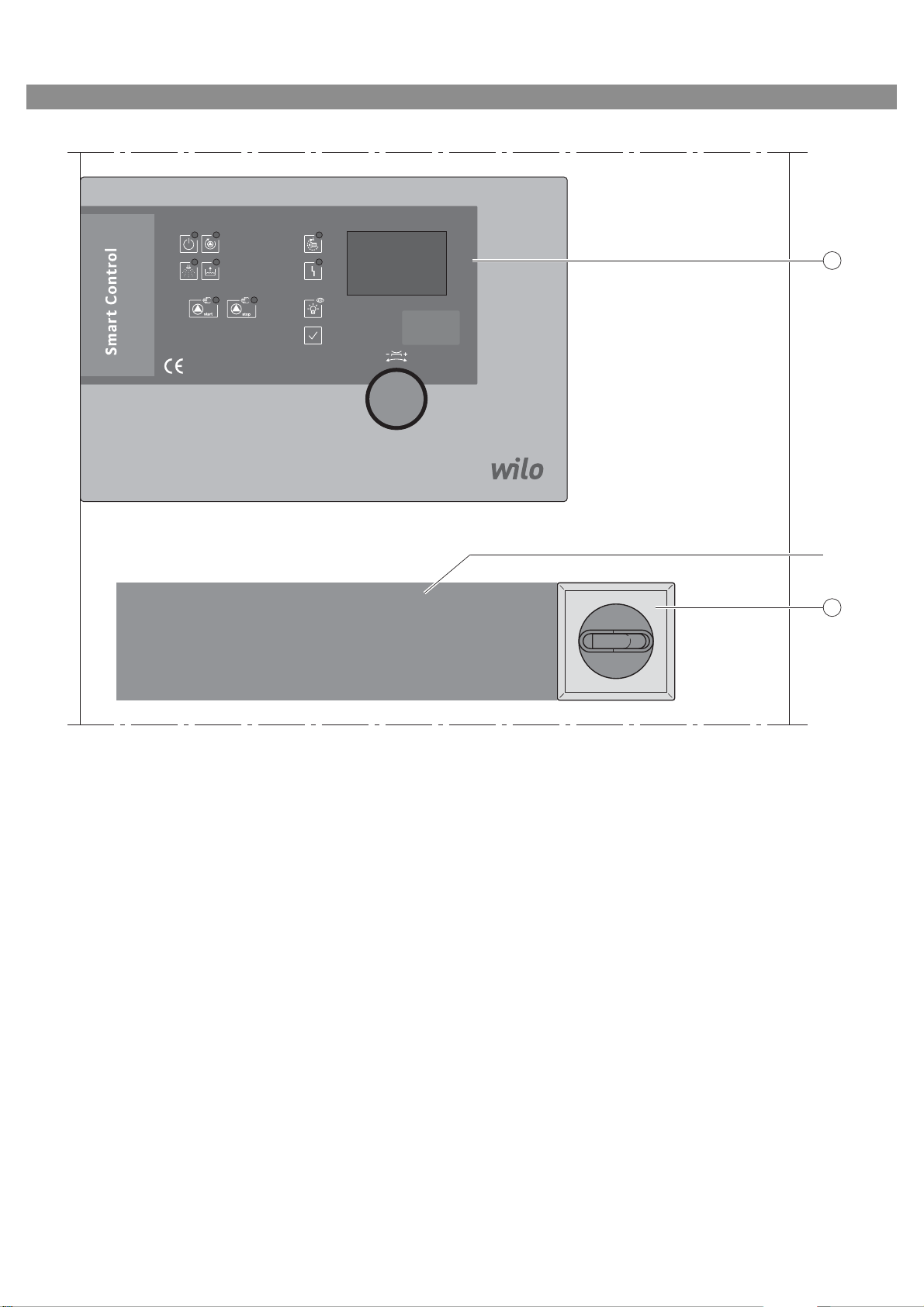
Fig. 1:
SPRINKLER PUMP MOTOR SUPPLY.
NOT TO BE SWICHED OFF
IN THE EVENT OF FIRE
I ON
0 OFF
1
2
**
Page 3

3
1
6
7
5
4
Page 4
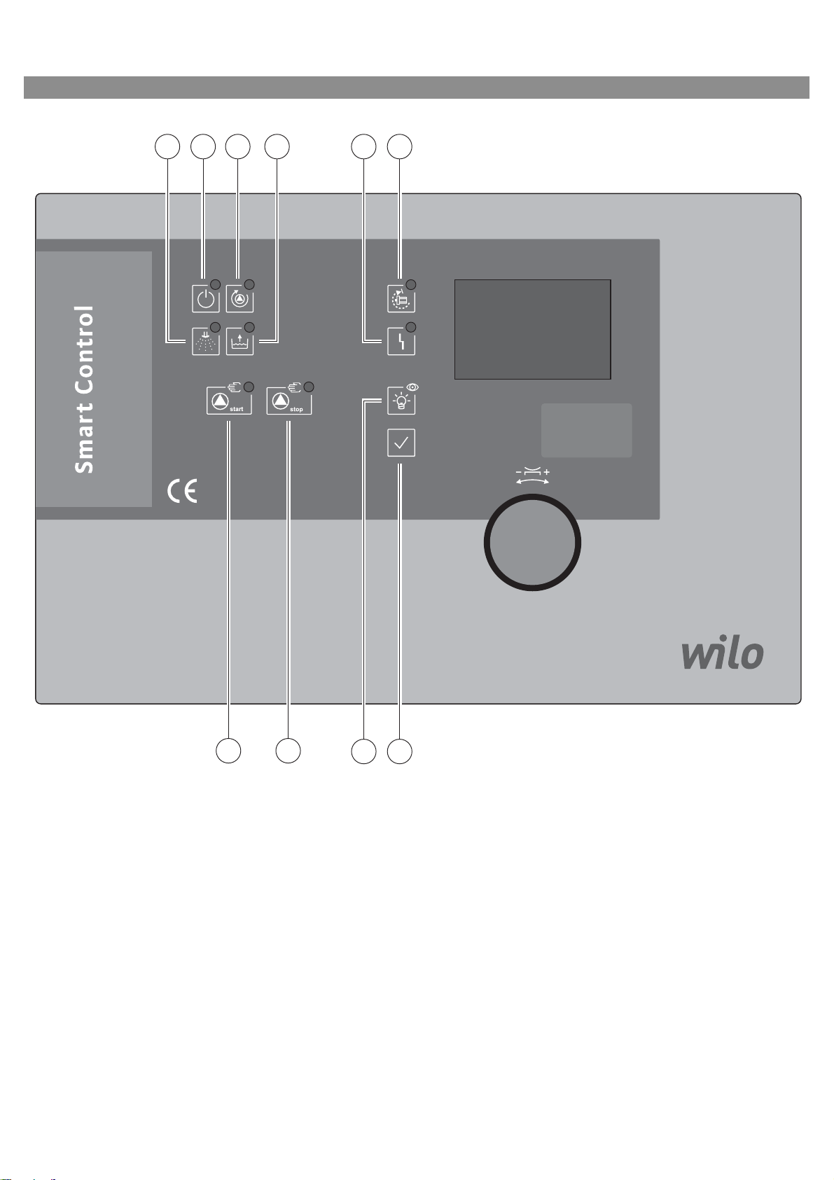
Fig. 2:
2 31 54 6
7 8
10
9
Page 5

Page 6
English
Captions
Fig. 1 Switchgear set-up
1 Menu selection and parameter input
2 Main switch: for switching the switchgear
on/off
3 Fusible cut-outs
4 Transformer:
3-phase pump current measurement
5 Contactors/contactor combinations
6 Base board: printed circuit board with micro-
controller
7 Measurement board:
converting current and voltage values
** Note regarding the main switch:
Power supply for the sprinkler pump motor.
DO NOT SWITCH OFF IN THE EVENT OF A FIRE!
Fig. 2 Switchgear display elements
1 LED (green): Operational standby
2 LED (green): Pump operation
3 LED (yellow): False start
4 LED (white): Sprinkler request
5 LED (white): Float switch request
6 LED (yellow): Collective fault
7 LED (green) and button: Manual start
8 LED (red) and button: Manual stop
9 Button: Lamp test
10 Button: Acknowledgement of error messages
26 WILO SE 01/2014
Page 7

English
Installation and operating instructions
1 General
1.1 About this document
The language of the original operating instructions is German. All other languages of these
instructions are translations of the original operating instructions.
These installation and operating instructions are
an integral part of the product. They must be kept
readily available at the place where the product is
installed. Strict adherence to these instructions is
a precondition for the proper use and correct
operation of the product.
These installation and operating instructions correspond to the relevant version of the product and
the underlying safety regulations and standards
valid at the time of going to print.
EC declaration of conformity:
A copy of the EC declaration of conformity is a
component of these operating instructions.
If a technical modification is made on the designs
amed there without our agreement or the decla-
n
rations made in the installation and
instructions on product/personnel safety are not
observed, this declaration loses its validity.
operating
2Safety
These operating instructions contain basic information which must be adhered to during installation, operation and maintenance. For this reason,
these operating instructions must, without fail, be
read by the service technician and the responsible
specialist/operator before installation and commissioning.
It is not only the general safety instructions listed
under the main point “safety” that must be
adhered to but also the special safety instructions
with danger symbols included under the following
main points.
2.1 Indication of instructions in the operating
instructi
Symbols:
General danger symbol
Danger due to electrical voltage
NOTE
Signal words:
DANGER!
Acutely dangerous situation.
Non-observance results in death or the most
serious of injuries.
WARNING!
The user can suffer (serious) injuries. ’Warning’
implies that (serious) injury to persons is probable if this information is disregarded.
ons
CAUTION!
There is a risk of damaging the pump/unit.
tion’ implies that damage to the product is likely
if this information is disregarded.
NOTE:
Useful information on handling the product. It
draws attention to possible problems.
Information that appears directly on the product,
such as:
• Direction of rotation arrow,
• Identification for connections,
• Rating plate,
• Warning sticker,
must be strictly complied with and kept in legible
condition.
2.2 Personnel qualifications
The installation, operating and maintenance personnel must have the appropriate qualifications
this work. Area of responsibility, terms of ref-
for
erence and monitoring of the personnel are to be
e
nsured by the operator. If the personnel are not in
possession of the necessary knowledge, they are
to be trained and instructed. This can be accomplished if necessary by the manufacturer of the
product at the request of the operator.
2.3 Danger in the event of non-observance of the
safety instructions
Non-observance of the safety instructions can
result in risk of injury to persons and damage to
the environment and the product/unit. Nonobservance of the safety instructions results in
the loss of any claims to damages.
In detail, non-observance can, for example, result
in the following risks:
• Danger to persons from electrical, mechanical and
bacteriological influences
• Damage to the environment due to leakage of
hazardous materials
• Property damage
• Failure of important produc
• Failure of required maintenanc
dures
2.4 Safety consciousness on the job
The safety instructions included in these installation and operating instructions, the existing
national regulations for accident prevention
together with any internal working, operating and
safety regulations of the operator are to be complied with.
2.5 Safety instructions for the operator
This appliance is not intended for use by persons
(including children) with reduced physical, sensory
or mental capabilities, or lack of experience and
knowledge, unless they have been given supervision or instruction concerning use o
by a person responsible for their safety.
Children should be supervised to ens
do not play with the appliance.
t/unit functions
e and repair proce-
f the appliance
’Cau-
ure that they
Installation and operating instructions Wilo SC-Fire Electric 27
Page 8

English
If hot or cold components on the product/the unit
lead to hazards, local measures must be taken to
guard them against touching.
Guards protecting against touching moving components (such as the coupling) must not be
removed whilst the product is in operation.
Leakages (e.g. from the shaft seals) of hazardous
fluids (which are explosive, toxic or hot) must be
led away so that no danger to persons or to the
environment arises. National statutory provisions
are to be complied with.
• Highly flammable materials are always to be kept
at a safe distance from the product.
• Danger from electrical current must be eliminated.
Local directives or general directives [e.g. IEC, VDE
etc.] and instructions from local energy supply
companies must be adhered to.
2.6 Safety instructions for installation and
maintenance work
The operator must ensure that all installation and
maintenance work is
qualified personnel, who are sufficiently informed
from their own detailed study of the operating
instructions.
Work on the product/unit must only be carried out
when at a standstill. It is mandatory that the procedure described in the installation and operating
instructions for shutting down the product/unit
be complied with.
Immediately on conclusion of the work, all safety
and protective devices must be put back in position and/or recommissioned.
carried out by authorised and
3 Transport and interim storage
Immediately after receiving the product:
• Check product for transport damage.
• In the event of damage in transit, take the necessary steps with the forwarding agent within the
respective time limits.
CAUTION! Risk of property damage!
Incorrect transport and interim storage can
cause property damage.
• The switchgear is to be protected against moisture and mechanical damage.
• It must not be exposed to temperatures outside
the range of -10°C to +50°C.
4 Application (intended use)
The SC Fire pump switchgear is used to control an
individual electric pump in automatic sprinkler
systems, in accordance with EN 12845.
The device is used in residential and office
ings, hospitals, hotels, administrative and industrial buildings.
The pump is used in conjunction with suitable signal transmitters and it is s
the pressure or on and off according to the level.
The intended use includes complying with these
instructions.
Any other use is considered to be outside the
intended use.
witched on according to
build-
2.7 Unauthorised modification and manufacture of
spare parts
Unauthorised modification and manufacture of
spare parts will impair the safety of the product/
personnel and will make void the manufacturer’s
declarations regarding safety.
Modifications to the product are only permissible
after consultation with the manufacturer. Original
spare parts and accessories authorised by the
manufacturer ensure safety. The use of other
parts will absolve us of liability for consequential
events.
2.8 Improper use
The operating safety of the supplied product is
only guaranteed for conventional use in accordance with Section 4 of the operating
The limit values must on no account fall under or
exceed those specified in the catalogue/data
sheet.
instructions.
28 WILO SE 01/2014
Page 9

5Product information
5.1 Type key
Example:
W W = Wilo
CTRL Control
SC Smart Control = control unit
F F = fire fighting purposes
1x Number of pumps
7.7 A Maximum rated motor current [A]
T4 T = 3 phases; 4 = 400 V
DOL
SD
FM
BM
ND3
ND4
E Switchgear for electric pump
Direct online (direct starting)
Star delta (star-delta starting)
Frame mounted (on a base frame)
Base mounted (free-standing cabinet)
New Design switchbox 400 x 1300 x 250 mm
New Design switchbox 400 x 950 x 250 mm
English
5.2 Technical data (standard version)
Mains supply voltage [V]: 3~400 V (L1, L2, L3, PE)
Frequency [Hz]: 50/60 Hz
Control voltage [V]: 230 VAC; 24 VDC
Max. current consumption [A]: See rating plate
Protection class: IP 54
Max. fuse protection on mains side [A]: See wiring diagram
Ambient temperature [°C]: 0 to +40°C
Electrical safety: Degree of contamination II
Alarm/signalling contact 250 VAC, 1 A
5.3 Scope of delivery
•Switchgear
•Wiring diagram
• Installation and operating instructions
• Test report acc. to EN 60204-1
5.4 Accessories
6 Description and function
6.1 Description of the product (Fig. 1)
6.1.1 Function description
The switchgear is used to control an individual
elec
tric pump in sprinkler systems, in accordance
with EN 12845. The pump can be switched on and
off by the control depending on the pressure. The
system’s operating statuses, such as standby,
pump operation, fault etc., are displayed visually
by LEDs on the door and operating parameters
such as current or voltage values are shown on the
display. The system is operated using the rotary
knob and the buttons in the door.
Potential-free contacts are available for forwarding run or fault signals mes
management system.
sages to the building
6.1.2 Set-up of the switchgear (Fig. 1)
The set-up of the switchgear depends on
capacity of the pump to be connected. It consists
of the following main components:
• Main switch: Switches the switchgear on/off
(Fig. 1, item 2)
• Human-machine interface (HMI): signal lamps or
display for indicating the operating status (e.g.
standby, fault, and rated pump current), rotary
knob and buttons for menu selection, parameter
input and operation (Fig. 1, item 1)
• Base board: printed circui
troller (Fig. 1, item 6)
• Measurement board: conver
age values (Fig. 1, item 7)
• Transformer: 3-phase pump current measurement (Fig. 1, item 4)
• Fuse protection for drives: fusing for the pump
motor by means of fusible cut-outs (Fig. 1, item 3)
• Contactors/contactor combinations: contactors
for switching on the pumps (Fig. 1, item 5)
the
t board with microcon-
ting current and volt-
Installation and operating instructions Wilo SC-Fire Electric 29
Page 10

English
6.2 Function and operation
DANGER! Risk of fatal injury!
When working on the open switchgear, there’s a
danger of electric shock from touching the live
components.
This work must only be carried out by qualified
personnel!
NOTE:
After connecting the switchgear to the supply
voltage, as well as after every mains interruption,
the switchgear returns to the operating mode set
before the power interruption.
6.2.1 Switchgear operating modes (Fig. 2)
Switching the switchgear on/off
After connection to the mains supply, the switchgear can be switched on or off using the main
switch. Once the main switch has been switched
on, the system is ready for operation after a few
seconds (the start phase). If the supply voltage is
within the set parameters, standby is indicated by
the signal lamp (Fig. 2, item 1) lighting up green.
Pump request
If the pressure drops below the set target pressure
at leas
t one of the two pressure switches, the signal lamp lights up (Fig. 2, item 4). After a configurable delay period (see menu 1.2.5.1) (LED flashes),
the connected pump is activated. The signal lamp
(Fig. 2, item 2) lights up green, indicating that the
pump is in operation.
Once the pressure reaches or exceeds the target
pressure, the signal lamp (Fig. 2, item 4) goes out
again but the pump remains activated. The pump
has to be switched off manually. The signal lamp
(Fig. 2, item 2) then goes out.
Priming device
If the level of the pump priming tank falls below
2/3, the float switch closes and the signal lamp
(Fig. 2, item 5) lights up white. After a configurable delay time (see menu 1.2.5.2) (LED flashes),
the pump activates and the signal lamp (Fig. 2,
item 2) lights
up green. Once the pump priming
tank is full and the float switch opens again, the
signal lamp goes out (Fig. 2, item 5) and the pump
eithe
r switches off again automatically or it has to
be deactivated manually (see menu 5.2.2.0).
The signal lamp (Fig. 2, item 2) then goes out.
Voltage monitoring
To improve operational reliability, the mains
power supply is monitored continuously. To do
this, the correct supply voltage has to be set in
menu 1.2.1.1. The voltage is monitored individually between all three live wires. If no pump is running (standby), the voltage in the display switches
alternately between all three conductors. When
the supply voltage exceeds or drops below the
configurable tolerances (see menu 5.4.1.0 and
5.4.2.0), the signal lamp (Fig. 2, item 1) goes out
after a configurable delay (see menu 1.2.5.3) and
the collective fault signal (Fig. 2, item 6) lights up
yellow. If a fault occurs, the pump nevertheless
starts or continues running. Once the voltage is
back within the tolerance range, the fault is selfacknowledging. The signal lamp (Fig. 2, item 6)
oes out and the signal lamp (Fig. 2, item 1) lights
g
up green again.
Current monitoring
The pump current is monitored while the pump is
in operation. To do this, the correct rated current
for the pump has to be set in menu 1.2.1.2. The
current is monitored individually in all three conductors. If the pump is running, the pump current
in the display switches alternately between all
three conductors. The signal lamp (Fig. 2, item 2)
lights up green once the pump current reaches a
configurable minimum threshold (see menu
5.4.3.0). When the pump current exceeds or drops
below the configurable tolerances (see menu
5.4.3.0 and 5.4.4.0), the signal lamp (Fig. 2, item 6)
ghts up after a configurable delay (see menu
li
1.2.5.5). If a fault occurs, the pump nevertheless
starts or continues running. Once the pump current is back within the tolerance range, the fault
can be
acknowledged. The signal lamp (Fig. 2,
item 6) goes out.
Monitoring hydraulic false start
Once the pump has started, the hydraulic output is
monitored by a pressure switch on the pump. If
the pump does not build up any pressure after the
configurable period of time (see menu 1.2.2.2) and
the pressure switch on the pump remains open,
the signal lamps (Fig. 2, item 6) and (Fig. 2, item 3)
light up. If the pump is running, the relevant pressure has been reached and the pump pressure
switch is closed accordingly, the fault can be
acknowledged. The signal lamps (Fig. 2, item 6)
and (Fig. 2, item 3) go out and the signal lamp
(Fig. 2, item 2) lights up green.
Monitoring electric false start
Once the pump has started
, the pump’s electric
output is monitored for a configurable period of
time after the start (see menu 1.2.2.1). To do this,
the correct pump output has to be set in menu
1.2.1.3. If the configurable minimum threshold (see
menu 5.4.5.0) is not reached within the monitoring
period, the signal lamps (Fig. 2, item 6) and (Fig. 2,
item
3) light up after a configurable delay period
(see menu 1.2.5.4) plus the time for the star/delta
changeover (see menu 1.2.5.6). If the pump is running and the relevant pump output has been
reached, the fault can be acknowledged. The signal
lamps (Fig. 2, item 6) and (Fig. 2, item 3) go out and
the signal lamp (Fig. 2, item 2) lights up green.
Logic reversal of the collective fault signal (SSM)
The required logic of the SSM can be set in menu
5.5.2.0. In this case, it is possible to select
between negative logic (falling edge in case of a
fault = “fall”) or positive logic (rising edge in case
of a fault = “raise”).
30 WILO SE 01/2014
Page 11

English
4
4
1
2
3
5
6.2.2 Operation of the switchgear
Operating elements
• Main switch on/off (lockable in “Off” position)
•The LCD shows the operating statuses of the
pump and the settings menu. The menu selection
and parameter input are performed using the
operating knob. Turn the knob to change values
or to scroll through a menu level; press it in order
to select and confirm:
The following graphic symbols are used:
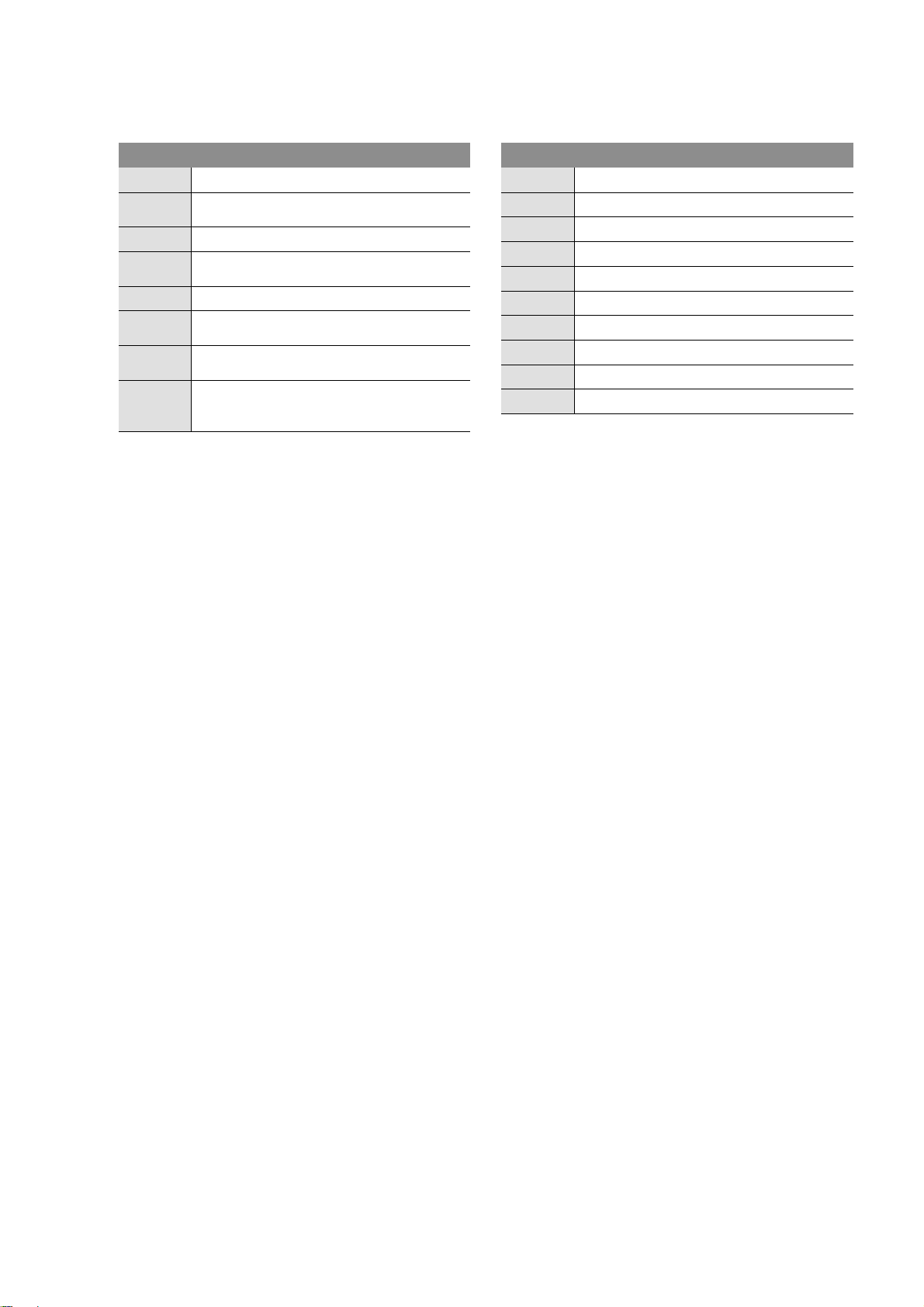
Information appears on the display as shown in
the sample illustration below:
Item Description
1 Menu number
2 Value display
3 Units display
4 Standard symbols
5 Graphic symbols
Symbol
Function/description Availability
Go back (brief press: one menu level; long press: main screen) all
EASY menu all
EXPERT menu all
Meaning: Service not logged in
all
Meaning: Display value – no entry possible
Service menu all
Parameter all
Information all
Fault all
Reset fault all
Installation and operating instructions Wilo SC-Fire Electric 31
Alarm settings all
Page 12

English
Symbol
Function/description Availability
Pump all
Setpoints all
Actual value all
Sensor signal all
Sensor measurement range Electrical equipment
Delay time all
Operating mode/application all
Stand-by all
Operating data all
Switchgear data:
all
Controller type; ID number; software/firmware
Operating hours all
Pump’s operating hours all
Switchgear’s switching cycles all
Pump’s switching cycles all
Communication all
Output parameters all
SSM parameter all
Set motor speed Diesel
32 WILO SE 01/2014
Page 13

English
Symbol
Function/description Availability
Starting time per start attempt Diesel
Pause between start attempts Diesel
Fuel Diesel
Battery A Diesel
Battery B Diesel
Sprinkler (pressure switch) all
Pump priming tank (float switch) all
Heating Diesel
Engine oil Diesel
Motor temperature thermostat Diesel
Cooling water (temperature) Diesel
Belt break Diesel
False start Electrical equipment
Pressure Electrical equipment
Mains power supply Electrical equipment
Voltmeter all
Ampere meter all
Star-delta switching Electrical equipment
Installation and operating instructions Wilo SC-Fire Electric 33
Page 14

English
Symbol
Function/description Availability
Freely configurable fault signal all
Fault input all
Start attempts counter Diesel
Duration all
Power meter Electrical equipment
Communication parameters all
Modbus all
BACnet all
Factory setting all
Resetting the settings to the factory settings all
Alarm counter all
Maintenance interval all
Reset all
Motor speed Diesel
Set motor speed Diesel
Minimum speed for “motor in operation” Diesel
Reset starting counter Diesel
Menu structure: The menu structure of the control system has
4 levels.
34 WILO SE 01/2014
Page 15

Navigation in the individual menus as well as the
parameter input are described in the following
example (selecting the transformer):
English
Installation and operating instructions Wilo SC-Fire Electric 35
Page 16

English
Refer to the following table for a description of the
individual menu items:
Menu
no./
Display Description Parameter range
Factory setting
The main screen shows the status of the system.
The display continuously switches between the
voltages of the live wires.
When the motor is running, the present pump current in all three live wires is shown alternately on
the display.
The EASY menu allows you to make settings for
the supply voltage, rated pump current and the
pump’s performance.
The EXPERT menu contains other settings that
can be used for a detailed setting of the switchgear.
The parameter menu for all settings that influence
operation.
The setting menu for the electrical parameters of
the connected pump.
Setting the supply voltage. 400
36 WILO SE 01/2014
Page 17

English
Menu
no./
Display Description Parameter range
Factory setting
Setting the rated pump current. 0.1..7.8..5000
Setting the pump motor’s output. 1..4..250
The setting menu for the monitoring operations
periods.
Setting the duration for monitoring of the pump’s
0..70..120
electric output (electric false start).
Setting the duration for monitoring of the pump’s
0..70..120
hydraulic output (hydraulic false start).
The setting menu for the delays.
Start delay when pressure switch trips 1..10
Start delay when float switch trips 1..10
Installation and operating instructions Wilo SC-Fire Electric 37
Page 18

English
Menu
no./
Display Description Parameter range
Factory setting
Delay in event of error message from voltage
0..1..10
monitoring
Delay for “electric false start” error message 0..1..20
Delay in event of error message from current
0..1..20
monitoring
Star-delta changeover time 0..5..60
Buffer time between deactivation of star contac-
0.00..0.05..1.0
tor and activation of delta contactor
Communication
Display of currently activated fieldbus OFF, Modbus, BAC-
net, GSM
Pump menu
38 WILO SE 01/2014
Page 19

English
Menu
no./
Display Description Parameter range
Factory setting
Drives on/off OFF, ON
Information
Current operating values
Voltage values
Voltage between conductors L1 and L2
Voltage between conductors L1 and L3
Voltage between conductors L2 and L3
Current values
Installation and operating instructions Wilo SC-Fire Electric 39
Page 20

English
Menu
no./
Display Description Parameter range
Factory setting
Pump current in L1
Pump current in L2
Pump current in L3
Output values
Pump output L1
Pump output L2
Pump output L3
Status information
40 WILO SE 01/2014
Page 21

English
Menu
no./
Display Description Parameter range
Factory setting
System status or readiness
Status of pressure switch
Status of float switch
Operating data
Total running time of the system
Total running time of pump
Unit switching cycles
Pump’s switching cycles
Installation and operating instructions Wilo SC-Fire Electric 41
Page 22

English
Menu
no./
Display Description Parameter range
Factory setting
System data
System type
Serial number as ticker format
Software version
Firmware version
Settings
Sensor settings
Transformer selection 30..1000
42 WILO SE 01/2014
Page 23

English
Menu
no./
Display Description Parameter range
Factory setting
Motor stop when started by float switch Manual, Auto
Limit values
Lower tolerance limit for supply voltage 0..10
Upper tolerance limit for supply voltage 0..10
Lower tolerance limit for rated pump current 0..10
Upper tolerance limit for rated pump current 0..10
Setting for minimum output necessary for detec-
0..80..100
tion that pump has started
Signal output parameters
Installation and operating instructions Wilo SC-Fire Electric 43
Page 24

English
Menu
no./
Display Description Parameter range
Factory setting
Characteristics of collective fault signal (SSM) Fall, Rise
Freely configurable fault signal
Acknowledgement process for fault signal Not store, ON store
Logic reversal of input signal Fall, Rise
Activation of configurable fault signal OFF, ON
Fault active:
Ever, Pump
Always
Only when pump in operation
Response delay 0..60
Fault signals
44 WILO SE 01/2014
Page 25

English
Menu
Display Description Parameter range
no./
6.1.0.1
to
6.1.1.6
Operation levels:
The parameterisation of the switchgear is divided
into the menu areas EASY and EXPERT.
For rapid commissioning using the factory presets,
it is enough to set the speed values and the speed
adjustment in the EASY area.
The EXPERT area is provided in case other
p ar am et e rs ne ed t o b e c ha ng ed , o r fo r r ea di ng ou t
data from the device.
Menu level 7.0.0.0 is reserved for Wilo customer
service.
• Manual start (Fig. 2, item 7) The pump is started
manually by pressing the button. The relevant signal lamp (Fig. 2, item 7) lights up green when the
button is pressed, indicating that the pump was
started manually, not automatically. The pump
can only be stopped manually. The signal lamp
(Fig. 2, item 7) then also goes out.
• Manual stop (Fig. 2, item 8) The pump is stopped
manually by pressing the button. The relevant
signal lamp (Fig. 2, item 8) lights up red when the
button is pressed, indicating that the pump was
stopped manually. The pump can only be stopped
using this button, except if the pump was started
by the float switch and “auto” has been set in
menu 5.2.2.0. The signal lamp (Fig. 2, item 8) goes
out the next time the pump starts again or when
the button (Fig. 2, item 10) is pressed.
• Lamp test (Fig. 2, item 9) Pressing the button
switches on all the signal lamps (Fig. 2, items 1, 2,
3, 4, 5, 6, 7, 8) for as long as the button is pressed,
in order to check that the lamps are working.
When you release the button, the signal lamps go
out again or only light up according to the function.
• Ack
nowledgement (Fig. 2, item 10) Pressing the
button resets all the error messages or signal
lamps provided that the cause of the error no
longer exists.
Resetting fault signals
Fault signal 1 to 16
6.2.3 Switchgear display elements
Factory setting
Operational standby
The signal lamp (Fig. 2, item 1) lights up green if
the power
supply is connected, activated via the
main switch and the power supply is within the
configurable tolerance range (see menu 5.4.1.0
and 5.4.2.0).
Pump operation
The signal lamp (Fig. 2, item 2) lights up green if
the pump is activated and the pump current is
within the configurable tolerance range (see me nu
5.4.3.0 and 5.4.4.0).
False start
When the pump starts, it is monitored by means of
two different parameters (hydraulic false start,
electric false start).
The signal lamp (Fig. 2, item 3) lights up yellow
after the pump has started and the configurable
minimum output (see menu 5.4.5.0) is not reached
within a configurable period of time (see menu
1.2.2.1).
The signal lamp (Fig. 2, item 3) lights up yellow
ter the pump has started and the pump pressure
af
switch (option) does not close again (pump under
pressure) after a configurable period of time (see
menu 1.2.2.2).
Sprinkler request
The signal lamp (Fig. 2, item 4) lights up white
if the pressure in the system falls below the set/
requested pressure and at least o
ne of the two
pressure switches trips. If the pressure rises
accordingly, the signal lamp (Fig. 2, item 4)
goes out again.
Float switch request
The signal lamp (Fig. 2, item 5) lights up white
when
the level in the pump priming tank falls to 2/
3 and the float switch is triggered. If the level rises
again accordingly, the signal lamp (Fig. 2, item 5)
goes out.
Installation and operating instructions Wilo SC-Fire Electric 45
Page 26

English
Collective fault
The signal lamp (Fig. 2, item 6) lights up yellow
when a fault occurs. Faults include a fault in the
supply network, over- or undercurrent, false
pump start and a fault in the freely configurable
fault signal. The signal lamp (Fig. 2, item 6) goes
out again once the fault no longer exists and the
fault has been acknowledged.
If “Automatic off” is set in menu 3.1.0.0, the signal
lamp (Fig. X, item 6) will flash yellow, because the
automatic mode is disabled.
Manual pump start
The signal lamp (Fig. 2, item 7) lights up green
when the pump is started manually using the button (Fig. 2, item 7). It goes out again when the
pump is stopped manually.
Manual pump stop
The signal lamp (Fig. 2, item 8) lights up red when
the button
ope
been acknowledged.
(Fig. 2, item 8) is pressed to stop pump
ration. It goes out once the pump stop has
7 Installation and electrical connection
Installation and electrical connection must be
carried out in accordance with local regulations
and only by qualified personnel!
WARNING! Risk of injury!
The existing directives for accident prevention
must be adhered to.
Warning! Danger of electric shock!
Danger from electrical current must be eliminated.
Local directives or general directives [e.g. IEC]
and instructions from local energy supply companies must be adhered to.
7.1 Installation
Install the switchgear/system at a dry location.
Protect the place of installation from direct exposure to sunlight.
7.2 Electrical connection
DANGER! Risk of fatal injury!
Improper electrical connections can lead to fatal
electric shocks.
• Have the electrical connection established by an
electrician approved by the local electricity supplier only and in accordance with local regulations.
• Observe the installation and operating instructions for the pumps and accessories!
• Disconnect the power supply before any work.
Warning! Danger of electric shock!
There is a potentially fatal voltage on the supply
side, even when the main switch is turned off.
• The type of mains, current and voltage of the
mains connection must match the details on the
rating plate of the control device.
NOTE:
• Fuse on mains side in acco
mation in the wiring diagram
• Feed the ends of the mains cable through the
threaded cable connections and cable inlets and
wire them according to the markings on the terminal strips.
• Earth the pump/installation in accordance with
the regulations.
NOTE:
In accordance with EN /IEC 61000-3-11 (see table
below), the switchgear and pump with motor
power of ... kW (column 1) are provided for operation on a mains power supply with a system imped-
ance of Zmax at the building connection of max. ...
Ohm (column 2) for a maximum number of ... connections (column 3).
If the mains impedance and the number of connections per hour are greater than the values
given in the table, the switchgear with the pump
may lead to temporary voltage drops and also to
disturbing voltage fluctuations (flickering) due to
the unfavourable mains conditions.
Therefore, measures may be necessary before the
switchgear
at this connection. The necessary information
must be obtained from the local electricity supply
company and the manufacturer.
with pump can be operated as intended
rdance with the infor-
46 WILO SE 01/2014
Page 27

English
3~400 V
2-pole
Direct starting
3~400 V
2-pole
S-D starting
Output [kW]
(Column 1)
System impedance [Ω]
(Column 2)
Connections per hour
(Column 3)
2.2 0.257 12
2.2 0.212 18
2.2 0.186 24
2.2 0.167 30
3.0 0.204 6
3.0 0.148 12
3.0 0.122 18
3.0 0.107 24
4.0 0.130 6
4.0 0.094 12
4.0 0.077 18
5.5 0.115 6
5.5 0.083 12
5.5 0.069 18
7.5 0.059 6
7.5 0.042 12
9.0 – 11.0 0.037 6
9.0 – 11.0 0.027 12
15.0 0.024 6
15.0 0.017 12
5.5 0.252 18
5.5 0.220 24
5.5 0.198 30
7.5 0.217 6
7.5 0.157 12
7.5 0.130 18
7.5 0.113 24
9.0 – 11.0 0.136 6
9.0 – 11.0 0.098 12
9.0 – 11.0 0.081 18
9.0 – 11.0 0.071 24
Installation and operating instructions Wilo SC-Fire Electric 47
Page 28

English
7.2.1 Power supply connection
Connect the on-site 4-wire cable (L1, L2, L3, PE)
for the supplying network to the main switch, in
accordance with the wiring diagram.
7.2.2 Fault signal/run signals connection
A signal can be taken from the terminal strip for
the fault signal/run signal via a potential-free
contact in order to indicate a fault/operation
(see wiring diagram).
Potential-free contacts, max. contact load
250 V~/1 A
Warning! Danger of electric shock!
There is a potentially fatal voltage on these terminals, even when the main switch is turned off.
8 Commissioning
WARNING! Risk of fatal injury!
Commissioning by qualified personnel only!
Improper commissioning poses a risk of fatal
i
njury. Have commissioning performed by quali-
fied personnel only.
DANGER! Risk of fatal injury!
When working on the open switchgear, there’s a
danger of electric shock from touching the live
components.
This work must only be carried out by qualified
personnel!
We recommend that you have the switchgear
commissioned by Wilo customer service.
Before switching on for the first time, the on-site
wiring must be checked, in particular the earthing.
Tighten all terminals prior to commissioning!
8.1 Switchgear settings
After switching on the main switch and expiration
of the start sequence in the display and of the signal lamps, the switchgear is ready for operat
and factory preset.
The factory settings can be rest
tomer service.
To ensure correct operation it is necessary to
implement and/or check certain settings in the
menu
Menu 1.2.1.1:
Setting of the supply voltage in volts.
Menu 1.2.1.2:
Setting of the pump’s rated current. Information
relating to the pump’s rated current is to be
inferred from the pump’s rating plate.
ored by Wilo cus-
ion
Menu 1.2.1.3:
Display of the pump’s capacity. The value used for
the capacity results from the set values for voltage
and current under menu 1.2.1.1. and menu 1.2.1.2.
Menu 5.2.1.0:
Setting of the transformer type (primary current
measuring range). Information relating to the
transformer type can be found on the transformer’s rating plate.
NOTE:
If the measuring line has not only been run
through the transformer but also wrapped around
it, the current value of the transformer is to be
halved for each wrapping.
Example:
The measuring line has been wrapped twice
around a 100/5A transformer.
1 wrapping = 50/5A transformer
2 wrappings = 25/5A transformer
A 25/5A transformer should th
menu.
Menu 3.1.0.0:
Setting of the operating mode to “Automatic on”
(automatic pump operation).
CAUTION! Risk of malfunctions!
If “Automatic off” is set, automatic mode is not
possible. The pump can only be switched on manually.
8.2 Checking the motor direction of rotation
By briefly switching on the pump, check that the
direction of rotation of the pump is correct. When
the pump motor runs out, compare the direction
of rotation of the fan wheel and the direction
specified on the pump housing.
If the direction of rotation of the pump is wrong,
swap over any two phases of the power cable.
erefore be set in the
9Maintenance
Have maintenance and repair work carried out
by qualified skilled personnel only!
DANGER! Risk of fatal injury!
There is a risk of fatal injury from electric shock
when
working on electrical equipment.
• The switchgear should be electrically isolated
and secured against unauthorised switch-on
during any maintenance or repair work.
• Any damage to the connection cable should only
ever be eradicated by a qualified electrician.
• The switchbox must be kept clean.
• Visual inspection of the electric system parts in
the switchbox
48 WILO SE 01/2014
Page 29

English
10 Faults, causes and remedies
DANGER! Risk of fatal injury!
There is a risk of fatal injury from electric shock
when working on electrical equipment.
Have faults remedied by qualified skilled personnel only! Follow the safety instructions in
Section “2 Safety”.
Before all work to remedy faults, disconnect the
unit from the power supply, and make sure it
cannot be switched back on by unauthorised
persons.
10.2 History memory for faults
A history memory has been set up for the switchgear and operates according to the FIFO principle
(first-IN, first-OUT).
Code Fault description Causes Remedy
E54.0 No bus communication to
HMI board
Connection to HMI board interrupted
10.1 Fault indication
If a fault occurs, the relevant fault signal LED lights
up, the collective fault signal and associated individual fault contact are activated and the fault is
displayed on the LCD (fault code number).
The fault can be acknowledged by pressing the
acknowledgement button (Fig. 2, item 10) or in
menu 6.1.0.0 by proceeding as follows:
The memory is configured for 16 faults. The fault
memory can be called up using menus 6.1.0.1 –
6.1.1.6.
Check connection
Request customer service
E4.0 Undervoltage Supply voltage too low on mains
side
E5.0 Overvoltage Supply voltage too high on mains
side
E61.0 Hydraulic false start Pump pressure switch indicates
no pressure after pump start
E11.0 Electric false start Motor’s minimum electric output
not reached after pump start
E23.0 Excess current Excessive rated pump current
during operation
Exx.x Undercurrent Insufficient rated pump current
during operation
E109.0 Freely configurable fault Depending on the fault configu-
ration
If the fault cannot be remedied, please contact
ur nearest Wilo customer service point or rep-
yo
resentative.
Check mains voltage/mains
supply, check fuses
Check mains voltage/mains
supply
Check pump/impeller, check
pipes for leaks, check pump’s
direction of rotation, check
pressure switch setting
Check settings, check pump/
impeller
Pump blocked or stiff, check
supply voltage
Check settings, check pump/
impeller
Depending on the fault configuration
Installation and operating instructions Wilo SC-Fire Electric 49
Page 30

Page 31

Page 32

Pioneering for You
WILO SE
Nortkirchenstraße 100
D-44263 Dortmund
Germany
T +49(0)231 4102-0
F +49(0)231 4102-7363
wilo@wilo.com
www.wilo.com
 Loading...