

Page 1
Pioneering for You
Wilo-Control SC-Fire Diesel A2P
en Installation and operating instructions
4 206 382-Ed.02 / 2016-11-Wilo
Page 2
English
Fig. 1
WILO SE 11/2016 2
Page 3
English
Fig. 1
Installation and operating instructions: Wilo-SC-Fire Diesel A2P 3
Page 4
English
Fig. 2
WILO SE 11/2016 4
Page 5
English
1 General
About this document
The language of the installation and original operating instructions is German. All other languages of these
instructions are translations of the original installation and operating instructions.
The installation and operating instructions are an integral part of the product. They must be kept close to the
product and be ready for use if necessary. Strict adherence to these instructions is a precondition for the proper
use and correct operation of the product.
These installation and operating instructions correspond to the relevant version of the product and the
underlying safety standards valid at the time of going to print.
EC-Declaration of conformity:
A copy of the EC-Declaration of conformity is an integral part of these installation and operating instructions.
If a technical modification is made on the designs listed therein without prior approval or the declarations made
in the installation and operating instructions on product/personnel safety are not observed, this declaration loses
its validity.
2 Safety
These installation and operating instructions contain important information which must be adhered to during
installation, operation and maintenance. For this reason, these instructions must, without fail, be read by the
service technician and the responsible specialist/operator before installation and commissioning.
It is not only the general safety instructions listed under the main point “safety” that must be adhered to but also
the special safety instructions with danger symbols included under the following main points.
2.1 Symbols and signal words used in the installation and operating instructions
Symbols:
Danger: Imminent hazardous situation.
Non-observance may result in death or severe injury.
Danger: Danger due to electrical voltage.
Non-observance may result in death or severe bodily injuries by electric shock.
Useful or important information
WARNING!
Non-observance may result in severe injury.
WARNING!
Non-observance may result in a risk of damage of material or of the unit.
Installation and operating instructions: Wilo-SC-Fire Diesel A2P 5
Page 6

English
NOTE:
Useful information on handling the product. It draws attention to possible problems.
Infor mation that appears directly on the product, such as:
• Direction of rotation arrow
• Identification for connections
• Rating plate
• Warni ng stickers
must be strictly complied with and kept in legible condition.
2.2 Personnel qualifications
The installation, operating and maintenance personnel must have the appropriate qualifications for this work.
Area of responsibility, terms of reference and monitoring of the personnel are to be ensured by the operator. If
the personnel are not in possession of the necessary knowledge, they are to be trained and instructed. This can
be accomplished if necessary by the manufacturer of the product at the request of the operator.
2.3 Danger in the event of non-observance of the safety instructions
Non-observance of the safety instructions can result in risk of injury to persons and damage to the environment
and the product/unit. Non-observance of the safety instructions results in the loss of any claims to damages.
In detail, non-observance can, for example, result in the following risks:
• Danger to persons due to electrical, mechanical and bacteriological influences.
• Damage to the environment due to leakage of hazardous materials.
• Property damage.
• Failure of important product/unit functions.
• Failure of required maintenance and repair procedures.
2.4 Safety consciousness on the job
The safety instructions included in these installation and operating instructions, the existing national regulations
for accident prevention together with any internal working, operating and safety regulations of the operator are
to be complied with.
2.5 Safety instructions for the operator
This appliance is not intended for use by persons (including children) with reduced physical, sensory or mental
capabilities, or lack of experience and knowledge, unless they have been given supervision or instruction
concerning use of the appliance by a person responsible for their safety.
Children should be supervised to ensure that they do not play with the appliance.
• If the product/unit poses a threat due to components being too hot or too cold, these components must
be protected by the customer against touching.
• Guards that protect against coming into contact with moving components (such as the coupling) must
not be removed whilst the product is in operation.
• Hazardous fluids (e.g. from the shaft seals) which have leaked (which are explosive, toxic or hot) must
be eliminated so that no danger to persons or to the environment arises. National statutory provisions
are to be complied with.
• Highly flammable materials are always to be kept at a safe distance from the product.
• Danger from electrical current must be eliminated. Local directives or general directives
[e.g. IEC, VDE etc.] and instructions from energy supply companies must be adhered to.
WILO SE 11/2016 6
Page 7

English
2.6 Safety instructions for installation and maintenance work
The operator must ensure that all maintenance and installation work is carried out by authorised and qualified
personnel, who are sufficiently informed based on their own detailed study of the installation and operating
instructions.
Work on the product/unit must only be carried out when at a standstill. It is mandatory that the procedure
described in the installation and operating instructions for shutting down the product/unit be complied with.
Immediately on conclusion of the work, all safety and protective devices must be put back in position and/or
recommissioned.
2.7 Unauthorised modification and manufacture of spare parts
It is strictly forbidden to use batteries for any other purpose than to start the diesel motor.
3 Transport and interim storage
Upon receipt of the product:
• Check for any damage that may have occurred during transit.
• In the event of damage in transit take the necessary steps within the period defined by the transport
company within the time constraints.
WARNING! Risk of material damage!
Non-compliant transport and interim storage may cause material damage to the product.
• The switchgear must be protected against humidity and any mechanical damage.
• The product must not be exposed to temperatures lower than -10 °C and higher than
+50 °C.
4 Intended use
The SC-Fire A2P Diesel switchgear controls pumps in automatic pumping installations used for fire-fighting
purposes (sprinkler systems).
The design of this switchgear adheres to the technical regulations defined in the T1-1 of the A2P trademark.
The installation, functioning and maintenance are also defined in these technical regulations.
The relevant fields of application are habitable buildings, offices, hospitals, hotels, administrative and industrial
buildings.
Installation and operating instructions: Wilo-SC-Fire Diesel A2P 7
Page 8
5 Product information
W
W = WIL O
CTRL
Operation
SC
Smart Control = Control unit
F
F = Fire fighting application
1x
Number of pumps
197 – 246 kW
M
Power supply: 1 x 230 V/50 Hz
FM
Frame mounted
ND
New design of the electrical/control cabinet
D
Diesel cabinet
FR
France – box conforms to A2P
Technical data
Mains connection voltage [V]:
Frequency [Hz]:
50/60 Hz
12/24 V DC
Absorbed current max [A]:
See the rating plate
Protection class:
IP44
Fuse protection max on mains side [A]:
See circuit diagram
Room temperature [°C]:
0 °C to +50 °C
Electrical safety:
Pollution degree II
Alarm/signal contact:
250 V AC, 1 A
5.1 Type key
Example: W-CTRL-SC-F-1x(2)KW-M-FM-ND-D-FR
(2) Rated power range of the diesel motor [kW]:
4.25 – 47.7 kW
66 – 145 kW
English
Table 1 - Type key
5.2 Technical data (standard execution)
Control voltage [V]:
Table 2 - Technical data
5.3 Scope of delivery
• Switchgear
• Circuit diagram
• Installation and operating Instructions
• Check log in accordance with EN 60204-1
1~230 V (L, N, PE)
5.4 Accessories
WILO SE 11/2016 8
Page 9

English
6 Description and function
6.1 Product description
6.1.1 Function
The switchgear is used to operate a diesel motor pump in the sprinkler system in accordance with A2P (T1-1).
The manual start-up of the diesel motor is done from the HMI of the switchgear.
Contrary to automatic start-up which is generated by a lack of pressure in one of the 2 pressure switches.
Each pump has 2 pressure switches and each pressure switch has an Auto/0/Manu key switch.
The automatic start-up of the diesel motor follows a start-up sequence which allows for the generation of 6 startup attempts, the 2 batteries are used in the course of this sequence.
The status of the unit can be seen on the front of the support box:
- From the LED panel
- From the LCD
- From the audible warning
The operation is performed by means of the rotary knobs, key switches and screen pushbuttons also located on
the front of the box.
It is possible to perform an emergency start by means of the 2 buttons on the front of the cabinet. In this way,
the battery voltage is directly applied to the terminals of the diesel starter, without going through the control.
The water level in the start-up tank is monitored at all times. If the level in the tank goes under 2/3 of the “full
tank” level, then the diesel motor starts up to supplement the level.
Potential-free contacts are ready to transmit the collective run/malfunction signals to the BMS device.
6.1.2 Structure of the switchgear
The structure of the switchgear may vary according to the performance of the pump to be connected.
The switchgear includes the following components:
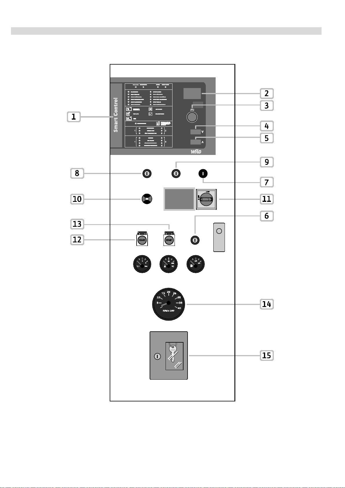
• Main switch (Fig. 1, pos. 11): Power supply of the switchgear
• Human Machine Interface (HMI):
o LCD screen enabling operational data to be displayed (see menus) (Fig. 1, pos. 2),
o LED indication of the status of the system (functioning/malfunctioning) (Fig. 1, pos. 1),
o Control button enabling menu navigation, menu selection and entering of parameters
(Fig. 1, pos. 1, 2, 3).
• Key switch (Fig. 1, pos. 8 and 9): Operation mode (Auto/0/Manu) of pressure switches 1 and 2
• Screen display indicating the voltage and battery charging current (Fig. 1, pos. 4, 5)
• Key switch (Fig. 1, pos. 6): access to level 2
• Battery selection switch (Fig. 1, pos. 7): selection of the battery for the voltage and current displays
(Fig. 1, pos. 4, 5)
• Audible warning: Activated in case of an alarm (Fig. 1, pos. 10)
Installation and operating instructions: Wilo-SC-Fire Diesel A2P 9
Page 10

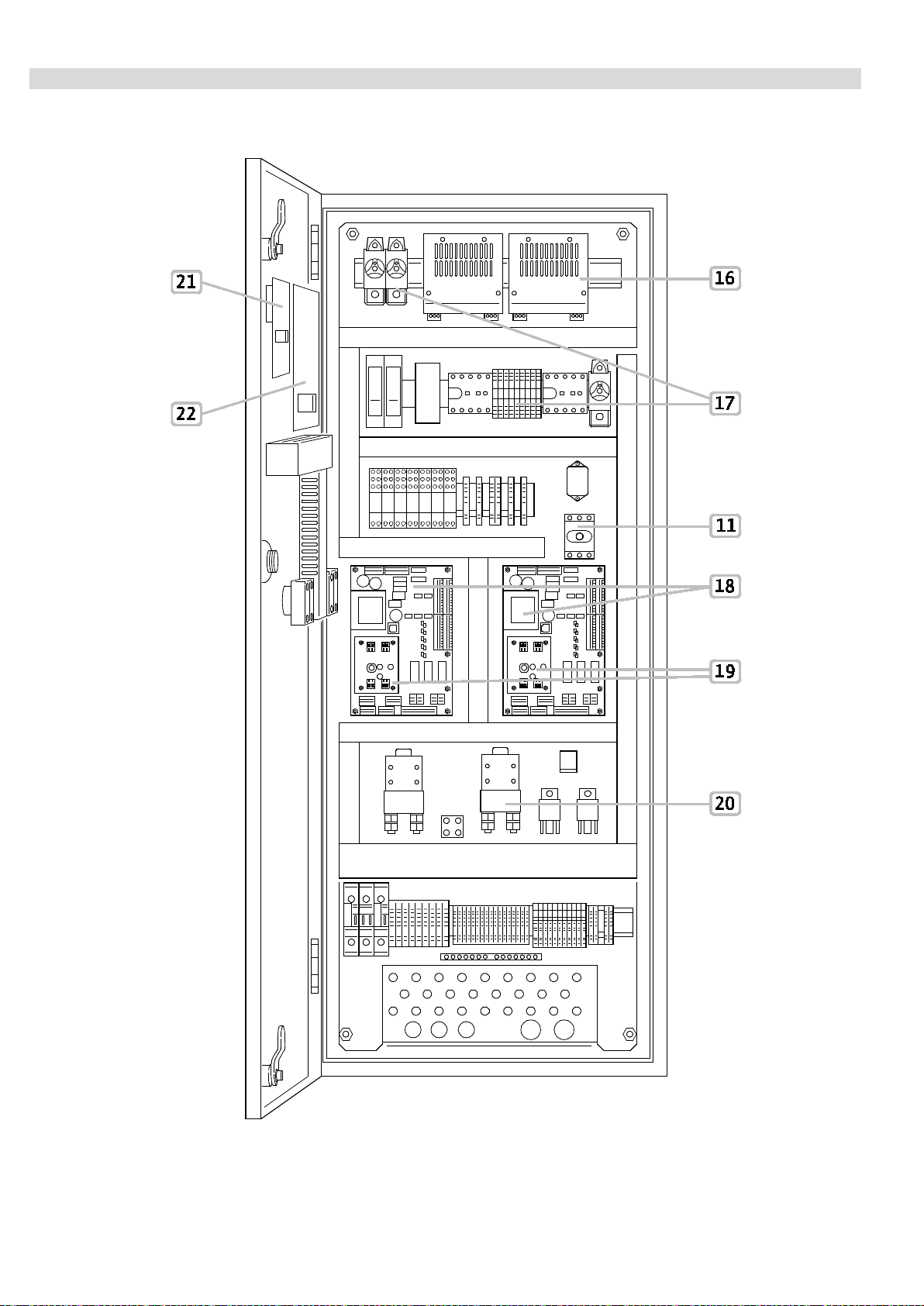
• Base printed circuit board: printed circuit board with micro-controller. (Fig. 1, pos. 18)
• Printed circuit board of the converter: conversion of the voltage from 12 V DC to 24 V DC, conversion
of the speed rotation signal (Fig. 1, pos. 19)
• Fuse protection of components: fuse protection of the control and connected components
(Fig. 1, pos. 17)
• Contactors/relay: contactors/relay to activate the starter and the electromagnets (Fig. 1, pos. 20)
• Chargers: To automatically charge and keep the diesel batteries charged (Fig. 1, pos. 16)
• Emergency start button: start-up of the diesel motor with battery 1 or 2, carried out independent of the
control (Fig. 1, pos. 12, 13)
• Diesel indicators (Fig. 1, pos. 14): display showing the fuel level, temperature of the cooling water, oil
pressure and speed of the diesel motor
• Key box: enables the storage of the keys from the key switches (Fig. 1, pos. 15)
• Printed circuit board “SC Display”: printed circuit board with display and rotary knob (Fig. 1, pos. 21)
• Printed circuit board “SC I/O”: printed circuit board with control/operating console (Fig. 1, pos. 22)
6.2 Function and operation
English
DANGER! Risk of fatal injury!
When working on an open switchgear, there is a risk of electrocution in the event of contact
with the conductor components.
Only authorised and qualified personnel may carry out the work!
Following connection of the switchgear to the connection voltage as well as after each network cutoff, the switchgear reverts to the operating mode set before the voltage cut-off.
6.2.1 Operating modes of the switchgear
Activation/deactivation of the switchgear
Once the batteries are connected to the switchgear and the voltage supply has been established, the control is
operational after a few seconds. The green LED indicating the operational readiness (Fig. 2, pos. 1) is turned
on.
By default, the remaining time before changeover to the other battery and charger is indicated on the LCD.
The chargers and the heating which maintain the temperature of the motor oil constant can be switched on or
off via the main switch.
To stop the operation, the terminals of connected batteries and the main switch must be disconnected.
WILO SE 11/2016 10
Page 11

English
Key switch no. 1 (for the pressure switch no. 1)
AUTO
OFF
MANUAL
the start-up tank
the start-up tank
the start-up tank
Operating mode
The operating mode of the switchgear is configurable via the 2 key switches, simply select one of the three
positions on the key switches “Auto”, “0” or “Manual”.
Diesel motor start-up in
case of
...
Activation of pressure
AUTO
switch no. 1
or
Malfunction of pressure
switch no. 1
or
Activation of pressure
switch no. 2
or
Malfunction of pressure
switch no. 2
or
Detection of a low level of
Activation of pressure
switch no. 2
or
Malfunction of pressure
switch no. 2
or
Detection of a low level
of the start-up tank
Activation of pressure
switch no. 2
or
Malfunction of pressure
switch no. 2
or
Detection of a low level of
the start-up tank
or
Key switch no. 1 in
“Manual” position
Key switch
no. 2
(for the
pressure
switch
OFF
no. 2)
MANUAL
Table 3: Operating modes
Activation of pressure
switch no. 1
or
Malfunction of pressure
switch no. 1
or
Detection of a low level of
Activation of pressure
switch no. 1
or
Malfunction of pressure
switch no. 1
or
Key switch no. 2 in
“Manual” position
or
Detection of a low level of
-
Key switch no. 2 in
“Manual” position
Key switch no. 1 in
“Manual” position
Key switch no. 1 in
“Manual” position
or
Key switch no. 2 in
“Manual” position
Automatic mode
To operate the unit in automatic mode, put the key switches (Fig. 1, pos. 8, 9) in the “Auto” position, the “Auto”
position is thus confirmed by the 2 green LEDs on the HMI (Fig. 2, pos. 30, 31).
The unit starts up automatically once the pressure switch no. 1 activates (drop in pressure, contact opening
width) and the key switch no. 1 is in the “Auto” position or once the pressure switch no. 2 activates and the key
switch no. 2 is in the “Auto” position.
The status of the pressure switches is signalled by a green or yellow LED (Fig. 2, pos. 34, 35).
In the event of a cable cut or connection malfunction of one of the 2 pressure switches, a red LED is activated
(Fig. 2, pos. 36, 37). This malfunction causes the diesel motor to start up automatically.
In automatic mode, the diesel motor also starts up if the level of the start-up tank is less than 2/3 full. The motor
only stops through the intervention of a technician.
Installation and operating instructions: Wilo-SC-Fire Diesel A2P 11
Page 12

English
Automatic start-up process
The automatic start-up consists of a sequence of six consecutive start-up attempts. Each attempt lasts
15 seconds and is followed by a pause of 10 to 15 seconds. After each start-up attempt, the other battery is
used for the following attempt. Even if there is no additional need on the float or key switch level, start-up
attempts continue. The number of attempts with each battery will be constantly indicated on the LCD.
All successful start-ups are signalled by a green LED (Fig. 2, pos. 3) and the output “running” is activated.
After six unsuccessful start-up attempts, an alarm signal is emitted, the output “failure to start” is activated and
the red “failure to start” LED is turned on (Fig. 2, pos. 5) as well as the yellow LED which signifies “attempt at
manual start-up” (Fig. 2, pos. 22) (see test of start-up device 6.2.1).
After a successful start-up sequence or after a phase of “failure to start”, the yellow LED named “Operat e the
test button for manual start-up if the indicator light is turned on” is turned on. (see device start-up test 6. 2.1).
Non-automatic mode
The key switch is not in the “Auto” position. Consequently, the corresponding pressure switch cannot activate
automatic start-up.
If neither of the two key switches is in the “Auto” position, then the start-up tank also cannot activate automatic
start-up. This operating mode is signalled by the red LEDs (Fig. 2, pos. 32, 33). Furthermore, the output
“NON-AUTO MODE 1/2” is active.
Manual mode
To perform a manual start-up, place one of the key switches in the “Man” position. The manual start-up (like the
automatic start-up) consists of a sequence of six consecutive start-up attempts. Each attempt lasts 15 seconds
and is followed by a pause of 10 to 15 seconds. After each start-up attempt, the other battery is used for the
following attempt.
Even when the key switch is not in the “Man” position, the start-up attempts continue.
Deactivation mode
To switch off the diesel motor, at least one of the key switches must be in the “0” position. As soon as the
pressure switch (or the float switch) is no longer activated, the diesel motor can be switched off by means of
the “OFF” button (Fig. 2, pos. 21).
Emergency start
Start by lifting the emergency start button protection cap (Fig. 1, pos. 12 et 13).
Subsequently, to start the diesel motor with battery no. 1, press the button “battery 1 emergency start”, and
keep the button pressed until start-up.
To start the diesel motor with battery no. 2, press the button “battery 2 emergency start”. In this start-up mode,
the starter is fed directly from the batteries.
Manual start-up device test
After a start-up sequence (manual or automatic) or after a failure to start, the yellow LED (Fig. 2, pos. 22)
recognised by the following indication is turned on: “OPERATE THE MANUAL START TEST BUTTON IF THE
INDICATOR LIGHT IS TURNED ON”.
In this case, the corresponding button must be pressed (Fig. 2, pos. 23) to perform the start-up device test.
WILO SE 11/2016 12
Page 13

English
Pump demand
If the set pressure configured is not reached for at least one of the two pressure on/off switches, the green or
yellow LED signals this (Fig. 2, pos. 34, 35). If these LEDs flash, this signifies that a configured dwell time has
elapsed (see menu 1.2.5.1). Once the set dwell time has elapsed, the corresponding LED remains turned on
while the pr essure switch is activated. The automatic start-up test run of the diesel motor is launched with a
maximum of 6 start-up attempts. The running-in period (menu 1.2.2.1) as well as the pause time (menu 1.2.2.2)
can be set using the software. After each start-up attempt, a switch to the other battery takes place. Any noncoupled pinions in the ring gear of the motor are detected. Connection is achieved by means of additional
attempts.
Successful start-up of the diesel motor is signalled by the green LED (Fig. 2, pos. 3). This lights up when the
measured rotation speed exceeds the threshold of the cut-in adjusted for “motor in operation” (menu 1.2.1.3).
The LCD displays the symbol of the pump and the battery currently being charged with the remaining time
before passing to the next charging system. The pinion for engaged starter is automatically disengaged. The
diesel motor can only be manually switched off with the “OFF” button (Fig. 2, pos. 21), if at least one of the key
switches is in the “Stop” position and if the change-over switch is not engaged. The green LED (Fig. 2, pos. 3)
turns off if the cut-in threshold for “motor in operation” is not reached. The LCD displays once more the
remaining time until passing to the other charging system.
Filling device
If the start-up tank level falls below 2/3 of its full level, then the “START-UP TANK MALFUNCTION” LED
(Fig. 2, pos. 12) is activated.
If the LED flashes, this signifies that a follow-up time is elapsing (see menu 1.2.5.2). Once the set follow-up time
has elapsed, the LED remains turned on while the float switch is activated.
This detection of a lack of water in the start-up tank launches the automatic start-up sequence of the diesel
motor, with a maximum of 6 start-up attempts. The running-in period (menu 1.2.2.1) as well as the time between
2 attempts (menu 1.2.2.2) can be adjusted. After each start-up attempt, a switch to the other battery takes
place. Any non-coupled pinions in the ring gear of the motor are detected.
A successful start-up of the diesel motor is signalled by a green LED (Fig. 2, pos. 3). This lights up when the
measured rotation speed exceeds the threshold of the cut-in adjusted for “motor in operation” (menu 1.2.1.3).
The LCD displays the symbol of the pump and the battery being charged with the remaining time before
passing to the next charging system. The diesel motor can be manually switched off with the “OFF” button
(Fig. 2, pos. 21), if at least one of the key switches is in the “Off” position and if the float switch is not engaged.
The green LED (Fig. 2, pos. 3) turns off if the cut-in threshold for “motor in operation” is not reached. The LCD
displays the remaining time before passing to the next charging system.
Monitoring of battery voltage
The cabinet is fitted with two battery chargers which are fed by the 230 V AC network.
The chargers deliver 12 V DC or 24 V DC, depending on the type of starter to be fed.
To maintain continuous service, the network voltage as well as the battery charges are constantly monitored.
Battery monitoring is ensured by the controller which constantly receives information from the two chargers.
The chargers can signal the following malfunctions to the controller:
- a rupture of the wire, coupling or connection,
- a short-circuit,
- a battery malfunction,
- a connection voltage error.
The malfunctions are analysed by the controller and displayed in the malfunction menu (Fig. 1, pos . 2).
Furthermore, it is possible to adjust the minimal battery voltage in the menu 5.4.1.0. If this voltage is not
achieved by one of the connected batteries, an error message is displayed on the screen.
Installation and operating instructions: Wilo-SC-Fire Diesel A2P 13
Page 14

English
Monitoring of motor start-up
Once the pressure switch/float switch is activated, or after a successful manual start-up, the automatic start-up
cycle of the motor is l aunched.
During the start-up phase, the controller monitors to ensure that the diesel motor is triggered.
The diesel motor is triggered when the start-up pinion is engaged in the gear ring of the motor.
If the diesel motor is not triggered after the first attempt, an error message appears on the screen. After each
start-up attempt, the other battery is used for the following attempt. After 6 unsuccessful start-up attempts, the
process is interrupted, the yellow LED “ATTEMPT START-UP” turns on (Fig. 2, pos. 22), an error message is
displayed on the screen and the malfunction signal contacts are active.
Duty cycling of the battery chargers
From the menu 5.3.1.0, it is possible to force the duty cycling of the active charger.
To do this, go to the menu 5.3.1.0, accessible from level 3, change the value “Auto” and select “Man”. The value
automatically reverts to “Auto”.
The battery charger which was active has swapped. The duty cycling countdown has also been reset to 0.
6.2.2 Application of the switchgear
Levels of access
• Level of access 1: Allows access to the functions without particular restrictions, such as for stopping
the buzzer (Fig. 2, pos. 18) or to proceed to a light test (Fig. 2 pos. 19).
• Level of access 2, intended for operators/owners, is accessible only after activation of the key switch
(Fig. 1, pos. 6). It enables access to certain functions such as the resetting of error messages (Fig. 2,
pos. 20) and the commissioning/decommissioning of the pre-heating diesel device (Fig. 2, pos. 17).
• Level of access 3, intended for the commissioner, is accessible with a code, given in the menu 7.0.0.0.
It enables access to all configurations of the menu.
Control elements
• Main switch (Fig. 1, pos. 11) On/Off (lockable in “Off” position).
• The LCD (Fig. 1, pos. 2) displays the pump operating status and the settings menu. The control button
(Fig. 1, pos. 3) allows menu selection and the entering of parameters (level 3 access required). To
modify the values or to scroll through a menu level, turn the knob and to select and confirm, press it:
WILO SE 11/2016 14
Page 15
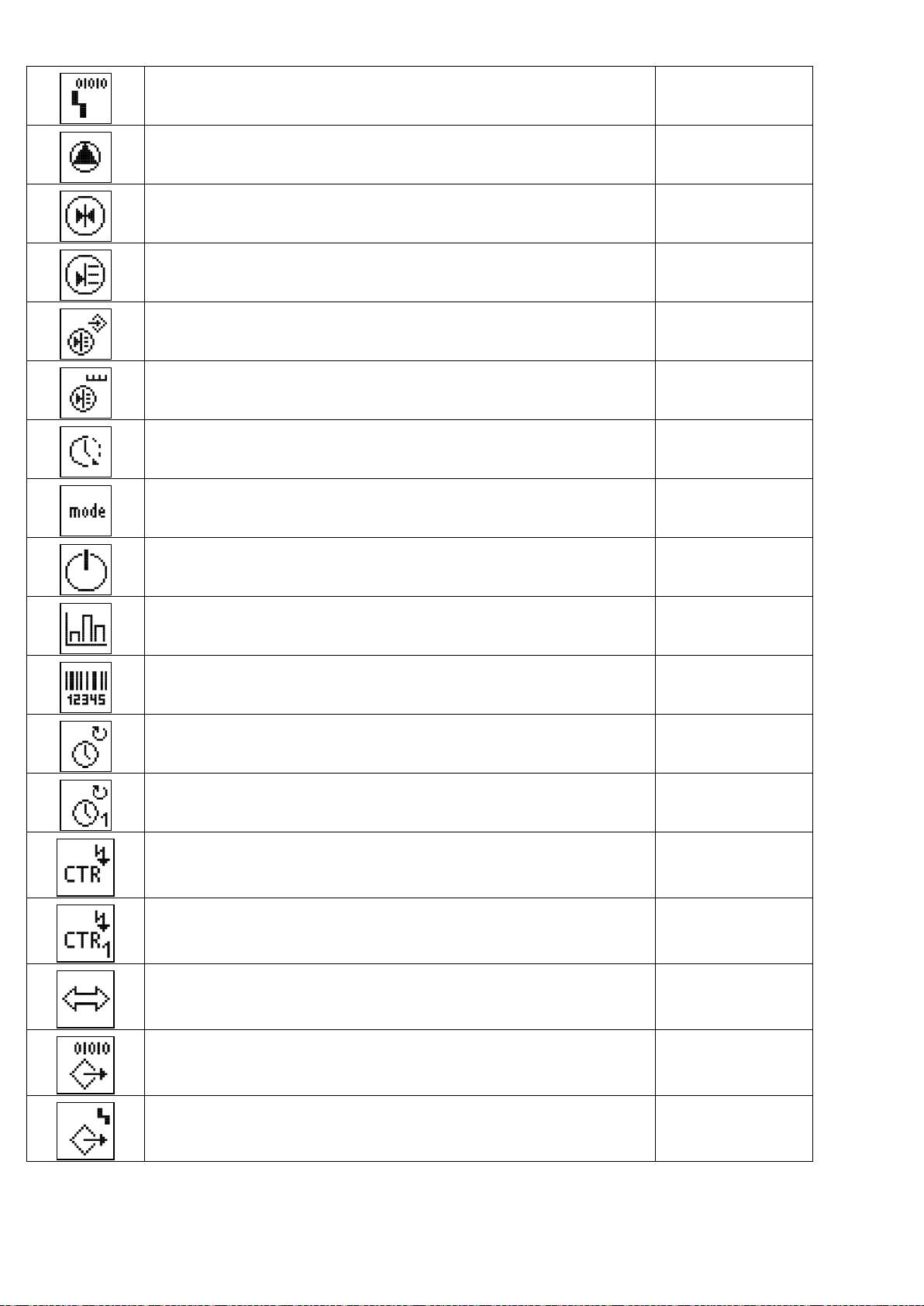
The information display is performed on the screen according to the following model:
Pos.
Description
1
Menu number
3
Unit display (text)
4
Standard symbols
5
Graphic symbols
Symbol
Function/description
Availability
2 Value display (text)
English
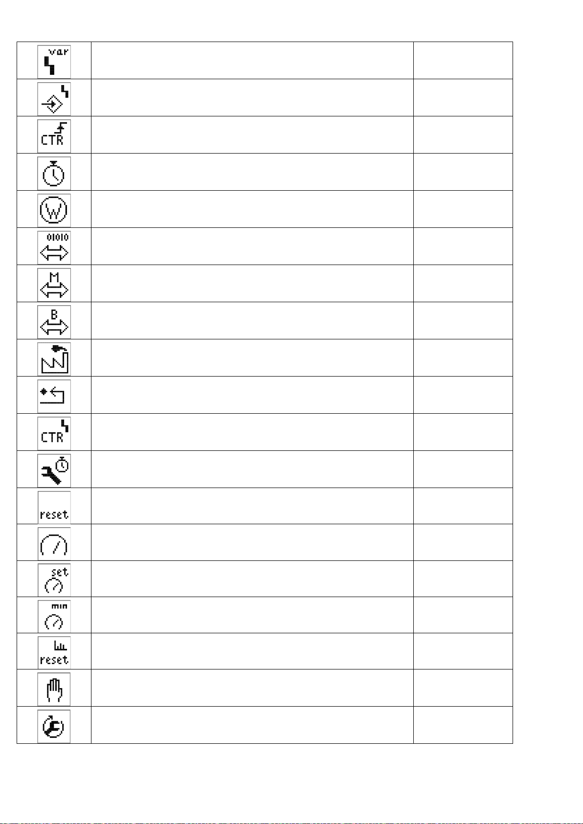
The following graphic symbols are used:
Return (brief press: a menu level; long press: main screen) All
EXPERT menu All
1. Notification: not connected
2. Notification: display value – no entry possible
Active/unlocked
Service menu All
Parameters All
All
Information All
Malfunction All
Reset malfunction All
Installation and operating instructions: Wilo-SC-Fire Diesel A2P 15
Page 16
Alarm settings All
Pump All
Setpoint All
Actual value All
Sensor signal All
Measurement sensor range Electric
Follow-up time All
English
Operating mode/application All
Stand-by All
Operational data All
Switchgear data:
All
Controller type; ID number; software/firmware
Operating hours All
Pump operating hours All
Switchgear operating cycles All
Pump operating cycles All
Communication All
Output parameters All
SSM parameters All
WILO SE 11/2016 16
Page 17

Definition of the motor rotation speed Diesel
Running-in period via start-up attempt Diesel
Pause between start-up attempts Diesel
Fuel Diesel
Battery 1 (A) Diesel
Battery 2 (B) Diesel
Sprinkler (pressure switch) All
English
Pump filling tank (float switch) All
Heating Diesel
Motor oil Diesel
Thermostat temperature of the motor Diesel
(Temperature of the water) for cooling Diesel
Belt rupture Diesel
Start-up interruption Electric
Pressure Electric
Power supply (mains) Electric
Voltmeter All
Ammeter All
Cut-in star-delta Electric
Installation and operating instructions: Wilo-SC-Fire Diesel A2P 17
Page 18
Malfunction signal freely configurable All
Malfunction input All
Start-up attempts counter Diesel
Duration All
Power indicator Electric
Communication parameters All
Modbus All
English
BACnet All
Factory setting All
Reset to the factory setting All
Alarm counter All
Maintenance interval All
Reset All
Motor rotation speed Diesel
Definition of the motor rotation speed Diesel
Minimum rotation speed for the signal “motor in operation” Diesel
Start-up counter reset Diesel
Manual Diesel
Commissioning Diesel
WILO SE 11/2016 18
Page 19

Menu structure:
The menu structure of the control system has 4 levels.
Navigation in the individual menus as well as the parameter input are described in the example of the
modification of the minimum battery voltage (level of access 3 required):
English
Installation and operating instructions: Wilo-SC-Fire Diesel A2P 19
Page 20

Refer to the following table for a description of the individual menu items.
When the motor is running, the pump
“Services” menu
Menu
no.
Menu accessible from the level of access no. 1
1.1.1.1 Screen 1.1.2 Description
English
Parameter range
Factory setting
The main screen displays the ba ttery
currently being charged a nd th e rem a ining
time before switching to the other ba ttery
charger [hh.mm].
symbol appears on the screen ( in the place
of the stand-by s ymbol) on the main
screens.
To access level 3 an access code must be
entered.
After 5 minutes of inactivity on HMI or after
a main supply malfunction, access is
blocked and the code must be re-entered.
“Malfunctions” menu
0…9999
WILO SE 11/2016 20
Page 21

English
6.1.0.1
History memory of m a lfunctions
the error counter can be reset via th e m enu
The main screen displays the ba ttery
The EXPERT menu contains other settings
which enable a detailed configur a tion of the
to
6.1.1.6
Menu accessible from the level of access no. 3
from 1 to 16
Remarks:
The history memor y of malfunctions and
7599 accessible on level 3.
currently being charged a nd th e rem a ining
time before switching to the other battery
charger [hh.mm].
The remaining time [in secs] before
deactivation of the level of access 3 in case
of inactivity on the HMI is also indicat ed on
the main screen (alternating every
5 seconds with the previous screen).
On the main screen, and when the motor is
running, the pump symbol a ppea r s in the
place of the stand-by symbol.
Menu unlocked with the correct access code
switchgear.
Installation and operating instructions: Wilo-SC-Fire Diesel A2P 21
Page 22

Access to the parameter menu enablin g
modification of the system operation.
Settings of the mot or r otation speed:
100 … 3000 … 4000
Once the preceding action has finished,
Finished
Minimum rotation speed from whic h the
200 … 800 … 3000
The parameter menu for a ll timer
English
The settings menu for the para meter s of
rotation speed.
When the diesel motor is running, and with
the aid of a tachome ter , (not provided), the
actual speed must be entered in order to
set parameters f or the controller.
validate the procedure by selecting “start”
from the menu, w hich will automatically
return to “finished”.
Start
controller deems that the “motor is in
operation”.
parameters influencing the operation.
WILO SE 11/2016 22
Page 23

English
Duration of each motor start-up atte m pt
5 … 15
Activation delay from the malfun ction
0 … 3 … 5
Pause duration be tween two start-up
attempts
Delays
Start-up delay in case of pressure switch
activation
5 … 10 … 15
1 … 10
Start-up delay in case of float switch
activation
“Empty fuel tank”
1 … 10
Installation and operating instructions: Wilo-SC-Fire Diesel A2P 23
Page 24

English
Communication
Pump menu
Information me nu
Display of active c om m unication bus No bus (no active bu s),
Modbus,
BACnet
Display of the au tom a tic mode status:
ON or OFF
Remarks: Th is information is the image of
the change-over switch status on the front
of the cabinet.
Service parameters
WILO SE 11/2016 24
Page 25

English
Battery voltage
Instantaneous voltage battery A
Instantaneous load current battery A
Instantaneous voltage battery B
Load currents
Installation and operating instructions: Wilo-SC-Fire Diesel A2P 25
Instantaneous load current battery B
Page 26

Counter for start-up attempts of the diesel
motor
English
Total start-up attem pt counter from
battery A
Total start-up attem pt counter from
battery B
Status of sensors
Status of pressure switch
Contact open
Or
Contact closed
Status of start-up tank float switch
(low level)
Contact open
Or
Contact closed
WILO SE 11/2016 26
Page 27

Status of float switch in the fuel tank
(low level)
Status of the the r m o c ontact of the diesel
Values of the sensors
Contact open
Or
Contact closed
English
Status of thermo contact of the dies e l
pre-heating device
Contact open
Or
Contact closed
oil
Contact open
Or
Contact closed
Status of the the r m o c ontact of the cooling
water of the diesel motor
Contact open
Or
Contact closed
Display of the oil pr e s s ure
Remarks:
At menu 5250 this sensor is deac tiv a ted as
not installed in th e s ystem.
Installation and operating instructions: Wilo-SC-Fire Diesel A2P 27
Page 28

Oil temperature
Temperature of the cooling water (external)
Display of instantaneous rotation speed of
Remarks:
At menu 5260 this sensor is deac tiv a ted as
not installed in th e s ystem.
English
Temperature of the cooling water
Remarks:
This sensor is not installed in the s ystem.
Remarks:
This sensor is not installed in the s ystem.
Rotation speed menu
the diesel motor
Display of the minimum rotation speed to
deem that the “mot or is in operation”
WILO SE 11/2016 28
Page 29

English
Operational data
Total hour coun ter of operation of the diesel
operation of the dies el
Number counter of cabinet pow er ups
Total hour coun ter of operation of the
SC-FIRE Diesel cabinet
motor
Total hour coun ter of
motor since the last s ta rt-up
Remarks:
Activation of the m ain switch or con nection
of batteries
Number counter of pump start-ups
Installation and operating instructions: Wilo-SC-Fire Diesel A2P 29
Page 30

English
System characteristics
Firmware version display
System type SC Diesel APSAD
Serial number display
Remarks: Text scrolling
Software version display
Adjustments
WILO SE 11/2016 30
Page 31

English
Communication
Parity
Even
Modbus
Baud delivery rate 9.6
19.2
38.4
76.8
Slave address
1 … 4 … 247
No (none)
Odd
Stop bits 1
2
Installation and operating instructions: Wilo-SC-Fire Diesel A2P 31
Page 32

English
BACnet
Stop bits
1
Baud delivery rate 9.6
19.2
38.4
76.8
Slave address 1 … 4 … 255
Parity Even
No (none)
Odd
2
BACnet Device Instance ID 0 … 24 … 9999
WILO SE 11/2016 32
Page 33

English
Adjustments of the sensors
Correspondence values for the oil
5.2.6.1
Input of resistance values for a
0 … 3000 (in ohms)
to
5.2.6.9
Oil pressure sensor activation OFF
ON
temperature sensor
temperature of 10 °C
Remarks:
The adjustment of the resistance p r ofile
continues in the menus 5.2.6. 2 to 5. 2. 6.9.
Activation of the m onitoring of belt failure OFF
ON
Forced cut-in of battery charger
Installation and operating instructions: Wilo-SC-Fire Diesel A2P 33
Page 34

English
Immediate duty cycling of a c tiv e c harger
Auto
Minimum battery voltage
0 … 30
Control of the commissioning sta r t -up
Finished, Start
Remarks:
By selecting the parameter “Man”, the
battery charger curren tly a c tiv e is r eversed.
And the countdown bef ore duty cycling is
reset to 0, visible on the main sc reen.
Limit values
Man
Control of the commissioning
Remarks:
Menu dedicated to the commission er.
Malfunction messages
WILO SE 11/2016 34
Page 35

Resetting of malfunction messages
Services menu
Adjustment of the serial nu m ber :
0…9999
This menu is equivalent to the reset button
malfunction on the front of the cabinet.
English
6.1.0.1
to
6.1.1.6
History memory of m a lfunctions
from 1 to 16
Access to the para m ete risation of the
cabinet
Designation of the cabinet
Adjustment of th e first 4 numbers of the
serial number
These numbers are adjusted in the factory
and cannot be modified.
Installation and operating instructions: Wilo-SC-Fire Diesel A2P 35
Page 36

Adjustment of the serial nu m ber :
Adjustment of th e last 4 numbers of the
0…9999
Software version display
Restoring of factor y parameters:
serial number
These numbers are adjusted in the factory
and cannot be modified.
English
Controller desig nation
Factory setting menu:
Possibility to res et the cabinet to factory
configuration
By pressing the red button, th e s ymbol
“factory” flas hes, turn the red button to the
right, the symbol “reverse arrow” appears ,
press the button a s e c ond time to launch
the resetting of the cabinet to factory
configuration.
Alarm menu
WILO SE 11/2016 36
Page 37

Error counter dis play, showing the number
of times that the error Exx.x has occ urred.
Additional menu functions
Modification of a ccess code to level 3:
Scroll through th e er ror codes with the red
button.
English
Resetting of the m a lfunction histor y and
error counter:
By pressing the red button, th e s ymbol
flashes, turn the red button to the right,
press the button a second time.
The malfunction history and the error
counter are now reset.
Activation code:
Enter the activa tion code, for example, to
activate a field bus c onnection.
To reset the access code, please call the
technical service.
Operational data of the menu reset
Installation and operating instructions: Wilo-SC-Fire Diesel A2P 37
Page 38

Resetting to zero of the total hour c ounter
of pump operation tim e and start-up
Resetting to zero of the total hour c ounter
Activation/deactivation of th e m aintenance
number counter:
By pressing the red button, th e s ymbol
flashes, then press the button a second
time.
English
Resetting to zero of the total hour c ounter
of operation time of battery 1
of operation time of battery 2
Maintenance and repair menu
interval
OFF
Or
ON
Adjustment of th e d uration in days for the
maintenance interval
0…92…1000
WILO SE 11/2016 38
Page 39

Resetting to zero of the maintenance
message:
Diesel mode display
Activation/deactivation of th e RIA
By pressing the r ed button, it is possible to
reset the maintena nce countdown
English
Application menu
RIA menu
application:
Protected access: To gain access, please
call the technical service.
Activation/deactivation of th e a p plication of
the hydrants:
Once access has been granted by the
technical service.
Installation and operating instructions: Wilo-SC-Fire Diesel A2P 39
Page 40

English
Adjust the time in minutes for the
1…20
automatic stop of the pump.
Operation levels:
Levels of use:
The parameterisation of the switchgear is divided into the menu areas EASY and EXPERT. Access to level 1
allows consultation of the breakdown history in the menu level 6.0.0.0 and the identification/connection sector
from menu 7.0.0.0. Access to level 3 allows consultation and parameterisation of the whole menu.
For rapid commissioning using the factory presets, it is enough to set the speed values and the speed
adjustment in the EASY area.
• Key switch (Fig. 1, pos. 48 et 49)
Pressure switch 1 and pressure switch 2 each have a key switch. The key switches can be locked in the
“Auto” position and their keys can only be withdrawn if the key switches are in the “Auto” position. Once the
“0” or “Manual” position has been selected, no automatic start-up with the pressure switch or float switch can
take place. The status corresponding to the “Auto” position is signalled by the green LEDs (Fig. 2, pos. 30,
31) and that which corresponds to the “0” or “Manual” position by the red LEDs (Fig. 2, pos. 32, 33).
If you turn one of the key switches in “Manual” mode, the diesel motor starts up manually with battery 1 or 2,
and six attempts maximum.
• Key switch (Fig. 1, pos. 6)
By turning the key switch into the “On” position, you will access the level 2 functions.
• Change-over switch (Fig. 1, pos. 7)
The change-over switch enables selection of battery 1 or 2. For the chosen battery, the voltage and current
are displayed on the screen (Fig. 1, pos. 4, 5).
• Emergency start button (Fig. 1, pos. 12, 13)
This button allows you to manually start the diesel motor with the corresponding battery and without
intervention of the control.
• “PRE-HEATING ON/OFF” (Fig. 2, pos. 17)
The heating ensuring a constant temperature of the motor oil turns on automatically as soon as the system is
powered up. This button enables the heating to be switched off and restarted (Level of access 2 required).
Once the heating is switched off, this malfunction is signalled by a red LED (Fig. 2, pos. 8) and a buzzer
signal.
• “BUZZER OFF” (Fig. 2, pos. 18)
This button allows an audible signal emitted in case of alarm to be cleared separately (level of access 1
required). As soon as a new malfunction arises, the buzzer signal sounds once again.
WILO SE 11/2016 40
Page 41

English
• “LAMP TEST” (Fig. 2, pos. 19)
If you press this button (level of access 1 required), all the control lamps and the alarm buzzer turn on for the
duration of the actuation, which allows you to check their good functioning. Once the button is released, the
control lamps and the alarm buzzer turn off once again or remain turned on only if the functioning demands
it.
• “CLEAR MALFUNCTION” (Fig. 2, pos. 20)
By pressing the button (level of access 2 required), all the error messages/control lamps are reset insofar as
the cause of the error has been eliminated.
• “OFF” (Fig. 2, pos. 21)
This button serves to switch off the motor. To do this, at least one of the switches must be in the “0” position.
The motor cannot be switched off if the pressure switch or float switch are not emitting anything. Once the
motor is switched off, the control lamp “ON” turns off (Fig. 2, pos. 3).
• “START-UP ATTEMPT BUTTON” (Fig. 2, pos. 23)
This attempt button and its control lamp (Fig. 2, pos. 22) are intended for the manual and regular test of the
electric start-up device. The button is used when an automatic motor start-up has taken place followed by a
manual stop, and following six consecutive failed start-up attempts. For these two operation statuses, the
control lamp turns on and the button must be pressed.
6.2.3 Display elements of the switchgear
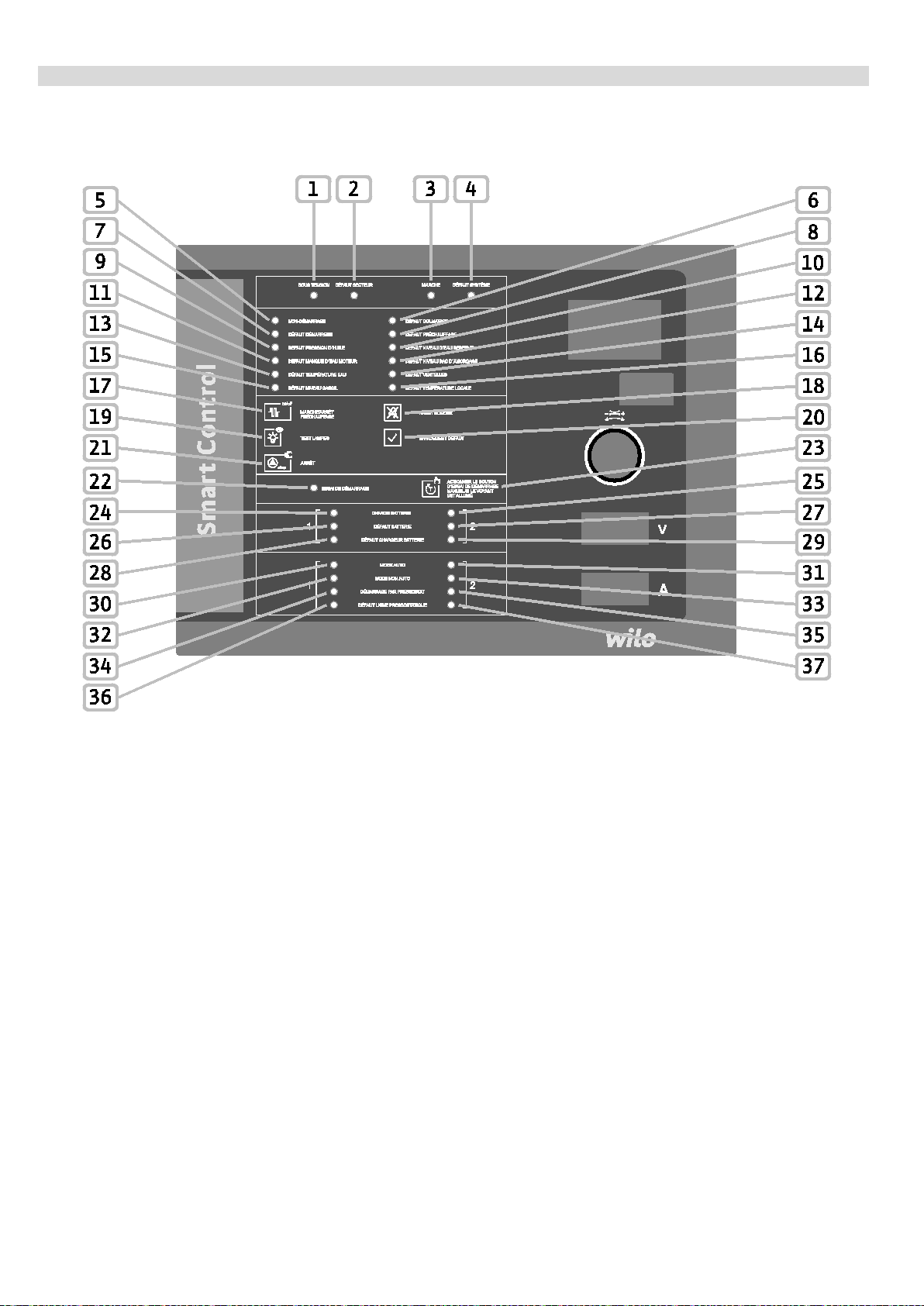
“LIVE” (Fig. 2, pos. 1)
The control lamp turns on green as soon as the power supply is established.
“MAINS MALFUNCTION” (Fig. 2, pos. 2)
In case of malfunction in the level of connection voltage (charger, heating) or inactive switch, the LED turns on
yellow with a follow-up time of 180 seconds.
“RUNNING” (Fig. 2, pos . 3)
The control lamp turns on green as soon as the diesel motor starts and when the rotation speed increased by
the rotation speed sensor has reached or exceeded the value pre-set for “motor in operation” (menu 1.2.1.3).
“SYSTEM MALFUNCTION” (Fig.2, pos. 4)
The yellow LED signals a software malfunction if the communication between the “printed circuit board I/O” and
the 2 printed circuit boards “SC controller” is interrupted or if the software routine (the programme) does not
function correctly.
“START-UP FAILURE” (Fig. 2, pos. 5)
The control lamp turns on red following six consecutive failed start-up attempts.
“CLOGGING MALFUNCTION” (Fig. 2, pos. 6)
The measurement of the differential pressure at the filter level has detected a clogged filter. This malfunction is
thus signalled by the LED turning on red.
“STARTER MALFUNCTION” (Fig. 2, pos. 7)
As soon as the switchgear no longer receives a response from the starter, the LED turns on red.
Installation and operating instructions: Wilo-SC-Fire Diesel A2P 41
Page 42

English
“PREHEATING MALFUNCTION” (Fig. 2, pos. 8)
The LED turns on red if the heating switches off or if the heating temperature switch or fuse is triggered.
“OIL PRESSURE MALFUNCTION” (Fig. 2, pos. 9)
The control lamp turns on red as soon as the oil pressure is detected to be too low by the automatic control of
the oil pressure. This error message can only be transmitted during diesel motor operation.
“WAT ER TANK LEV EL MALFUNCTION” (Fig. 2, pos. 10)
If the water tank level is too low, this LED turns on red.
“LACK OF MOTOR WATER MALFUNCTION” (Fig. 2, pos. 11)
The level of the cooling water is monitored. If the level is too low, this LED turns on red.
“START-UP TANK LEVEL MALFUNCTION” (Fig. 2, pos. 12)
The control lamp flashes red as soon as the level of the pump filling tank corresponds to 2/3 of the tank and
when the float switch is triggered. Once the start-up delay has elapsed (menu 1.2.5.2), the control lamp is
permanently turned on red. If at least the key switch is in the “Auto” position, the diesel motor starts
automatically.
“WATER TEMPERATURE MALFUNCTION” (Fig. 2, pos. 13)
The control lamp turns on red as soon as the temperature is detected to be too high by the connected
thermostatic valve. This error message can only be transmitted during diesel motor operation.
“VENT MALFUNCTION” (Fig. 2, pos. 14)
Once the diesel motor starts up, the aeration valves must open within 10 seconds. If no signal is emitted after
10 seconds, the LED turns on red.
“DIESEL LEVEL MALFUNCTION” (Fig. 2, pos. 15)
The control lamp turns on red as soon as the float switch of the fuel tank is triggered.
“ROOM TEMPERATURE MALFUNCTION” (Fig. 2, pos. 16)
As soon as the room temperature drops below 10 °C, the control lamp turns on red.
“START-UP ATTEMPT” (Fig. 2, pos. 22)
The control lamp turns on yellow when an automatic start-up of the motor has been triggered by the pressure
switch, followed by manual switch off, as well as after six consecutive failed start-up attempts.
“BATTERY LOAD 1/2” (Fig. 2, pos. 24, 25)
The two batteries are recharged alternately, every 24 hours. The corresponding green LED indicates the battery
which is being recharged.
“BATTERY MALFUNCTION 1/2” (Fig. 2, pos. 26, 27)
The voltage of the batteries is monitored. Furthermore, any absence of short-circuit or line break is checked. As
soon as a malfunction occurs, the LED turns on yellow.
“BATTERY CHARGER 1/2 MALFUNCTION” (Fig. 2, pos. 2 8, 29)
The connection voltage of the battery chargers is monitored. Furthermore, any absence of error or
communication malfunction is checked. As soon as a malfunction occurs, the LED turns on yellow.
WILO SE 11/2016 42
Page 43

English
“AUTO MODE 1/2 ” (Fig. 2, pos. 30, 31)
The green LED turns on if the corresponding key switch is in the “Auto” po sition. In the automatic mode, the
automatic start-up of the diesel motor is possible either via the intermediary of the float switch or the
corresponding pressure switch.
“NON-AUTO MODE 1/2” (Fig. 2, pos. 32, 33)
The green LED turns on if the corresponding key switch is in the “0” or “Manual” position. In the non-automatic
mode, no automatic start-up of the diesel motor is possible via the intermediary of the float switch or the
corresponding pressure switch.
“START-UP VIA PRESSURE SWITCH 1/2” (Fig. 2, pos. 34, 35)
The control lamp flashes green as soon as the pressure of the unit drops below the set/requested pressure and
when pressure switch 1 or 2 is triggered. Once the start-up delay has elapsed (menu 1.2.5.1), the control lamp
is permanently turned on. If the pressure increases as a consequence, the control lamp turns off once again. If
the key switch 1 or 2 is in the “Auto” position, the diesel motor starts automatically. If the pressure increases
and the output button (Fig. 2, pos. 20) is activated (level of access 2 required), the indicator light turns back on.
“PRESSURE SWITCH LINE 1/2 M ALFUNCTION” (Fig. 2, pos. 36, 37)
The connection of the pressure switches is monitored. Any short-circuit or cable rupture is signalled by the LED
turning on red. If the corresponding key switch is in the “Auto” position, the diesel motor starts up automatically.
Even in the absence of problems, the number of start-up attem pts is limited t o 6.
7 Installation and electri ca l c onne c t ion
Installation and electrical connection must be carried out in accordance with local regulations and only
by qualified personnel!
WARNING! Risk of personal injury!
Comply with applicable accident prevention regulations.
Warning! Danger of electric shock!
Danger from electrical current must be eliminated.
Local directives or general directives [e.g. IEC] and instructions from local energy supply
companies must be adhered to.
7.1 Installation
Install the switchgear/unit in a dry location.
Protect the place of installation from direct exposure to sunlight.
Installation and operating instructions: Wilo-SC-Fire Diesel A2P 43
Page 44

7.2 Electrical connection
DANGER! Risk of fatal injury!
In case of non-compliant electrical connection, there is a danger of death by electrocution.
• Have the electrical connection established by an electrician approved by the local energy
supply company only and in accordance with local regulations.
• Observe the installation- and operating instructions for the pumps and accessories.
• Disconnect the power supply before any work!
Warning! Danger of electric shock!
There is a potentially fatal voltage on the supply side, even when the main switch is turned
off.
• The type of mains, current type and voltage of the mains connection must match the details on the
rating plate of the control device.
English
NOTE:
• Fuse on mains side in accordance with the information in the wiring diagram.
• Feed the ends of the mains cable through the threaded cable connections and cable inputs and wire
them according to the markings on the terminal strips.
• Earth the pump/system in accordance with the regulations.
7.2.1 Power supply connection
Connect the on-site 3-wire cable (L, N, PE) for the power supply network to the main switch, in accordance with
the wiring diagram.
7.2.2 Battery connection
The batteries must be connected by means of the cables provided for that purpose. The screws of the hose
clamps must be fully tightened.
7.2.3 Connection of the malfunction signals/run signals
A signal can be withdrawn via a potential-free contact on the terminal strip for the malfunction/running
messages in order to signal a malfunction/operation (see wiring diagram).
Potential-free, contact load max. 250 V ~/1 A
WILO SE 11/2016 44
Page 45

English
“GENERAL MALFUNCTION”
Activation of the signal output if the following malfunctions occur:
• “MAINS MALFUNCTION”
• “PRE-HEATING MALFUNCTION”
• “OIL PRESSURE MALFUNCTION”
• “WATER TEMPERATURE MALFUNCTION”
• “BATTERY 1/2 MALFUNCTION”
• “BATTERY CHARGER 1/2 MALFUNCTIO N”
“RISK OF FAILURE”
Activation of the signal output if the following malfunctions occur:
• “SYSTEM MALFUNCTION”
• “CLOGGING MALFUNCTION”
• “STARTER MALFUNCTION”
• “WATER TANK LEVEL MALFUNCTION”
• “LACK OF MOTOR WATER MALFUNCTION”
• “START-UP TANK LEVEL MALFUNCTION”
• “VENT MALFUNCTION”
• “DIESEL LEVEL MALFUNCTION”
• “ROOM TEMPERATURE MALFUNCTION”
• “PRESSURE SWITCH LINE 1/2 MALFUNCTION”
“NON-AUTO MODE 1”
The signal output is activated if the corresponding key switch is in the “0” or “Manual” position. In the nonautomatic mode, no aut omatic s tart-up of the diesel motor is possible via the intermediary of the float switch or
the corresponding pressure switch.
“NON-AUTO MODE 2”
The signal output is activated if the corresponding key switch is in the “0” or “Manual” position. In the nonautomatic mode, no automatic start-up of the diesel motor is possible via the intermediary of the float switch or
the corresponding pressure switch.
“ON”
The signal output is activated as soon as the diesel motor has started and when the rotation speed increased
by the rotation speed sensor has reached or exceeded the pre-set value for a “motor in operation”
(menu 1.2.1.3).
“START-UP FAILURE”
The output signal is activated following six consecutive failed start-up attemp ts.
Installation and operating instructions: Wilo-SC-Fire Diesel A2P 45
Page 46

English
MALFUNCTION”
Colour of the LED
Buzzer
“GENERAL
“RISK OF FAILURE”
“NON-AUTO MODE 1/2”
“ON”
“LIVE” green
“MAINS MALFUNCTION” yellow x
“ON” green x
“SYSTEM MALFUNCTION” yellow x x
“START-UP FAILURE” red x x
“CLOGGING MALFUNCTION” red x x
“STARTER MALFUNCTION” red x x
“PRE-HEATING MALFUNCTION” red x x
“OIL PRESSURE MALFUNCTION” red x x
“WATER TANK LEVEL MALFUNCTION” red x x
“LACK OF MOTOR WATER MALFUNCTIO N” red x x
“START-UP TANK LEVEL MALFUNCTION” red x x
“WATER TEMPERATURE MALFUNCTION” red x x
“VENT MALFUNCTION” red x
“DIESEL LEVEL MALFUNCTION” red x x
“START-UP FAILURE”
“ROOM TEMPERATURE MALFUNCTIO N” red x
“START-UP ATTEMPT” yellow
“BATTERY LOAD 1/2” green
“BATTERY 1/2 MALFUNCTION” yellow x
“BATTERY CHARGER 1/2 MALFUNCTI ON” yellow x x
“AUTO MODE 1/2” green
“NON-AUTO MODE 1/2” red x
“START-UP VIA PRESSURE SWITCH 1/2” green/yellow
“PRESSURE SWITCH LINE 1/2 MALFUNCTION” red x x
Table 4: Malfunctio n signals and run signals
Warning! Danger of electric shock!
There is a potentially fatal voltage on these terminals, even when the main switch is turned
off.
WILO SE 11/2016 46
Page 47

8 Commissioning
WARNING! Risk of fatal injury!
Commissioning by qualified personnel only!
Improper commissioning poses a risk of fatal injury.
Have commissioning performed by qualified personnel only.
DANGER! Risk of fatal injury!
When working on an open switchgear, there is a risk of electrocution in the event of contact
with the conductor components.
This work must only be carried out by qualified personnel!
We recommend that you have the switchgear commissioned by Wilo customer service.
Before switching on for the first time, the on-site wiring must be checked, in particular the earthing.
Tighten all connection terminals prior to commissioning!
English
8.1 Factory setting
The control is pre-set at the factory.
The factory setting can be restored by Wilo customer service.
8.2 Rotation speed correction control
The motor rotation speed is fixed at the factory. To check it, the motor is to be started up by a manual function.
Once the motor is running, increase the rotation speed by means of a portable tachometer and compare it to
the rotation speed displayed on the screen. If the two rotation speeds match, no correction is required.
In case of significant difference, a further correction must be carried out. To do this, proceed as follows. Set the
motor at a constant and known rotation speed. Enter this value in the menu 1.2.1.1 and confirm. Move on to the
following menu item. In the menu 1.2.1.2, modify the setting by selecting “Start”, then confirm. Once the
correction is performed, the message “Finished” is displayed on the screen. The rotation speed correction was
successful and has been recorded. The motor can be switched off with the “OFF” button if at least one of the
key switches is in the “0” position.
8.3 Rotation speed correction control
Commissioning at the place of installation requires the automatic device test of the diesel motor start-up. To do
this, the fuel supply must be interrupted. In the menu 5.9.1.0, set “Start”, then confirm. Then push the button
“CLEAR FAULT” (Fig. 2, pos. 20) in the following 10 seconds. 6 automatic start-up attempts thus take place.
After 6 start-up attempts, the yellow LED (Fig. 2, pos. 22) signifies a failed start-up. The fuel supply must be
restored and the motor must start up as soon as the button is pushed (Fig. 2, pos. 23).
Installation and operating instructions: Wilo-SC-Fire Diesel A2P 47
Page 48

9 Maintenance
Have maintenance and repair work carried out by qualified skilled personnel only!
DANGER! Risk of fatal injury!
There is a risk of fatal injury from electric shock when working on electrical equipment.
• The switchgear should be electrically isolated and secured against unauthorised switch-
on during any maintenance or repair work.
• Any damage to the connection cable should only ever be eradicated by a qualified
electrician.
• The switchgear must remain clean.
• Visual inspection of the electrical components of the system in the switchgear.
10 Malfunctions, causes and remedies
English
DANGER! Risk of fatal injury!
There is a risk of fatal injury from electric shock when working on electrical equipment.
Have malfunctions remedied by qualified skilled personnel only! Observe the safety
instructions under Fehler! Verweisquelle konnte nicht gefunden werden.
Before performing any work to remedy malfunctions, disconnect the unit from the power
supply, and make sure it cannot be switched back on by unauthorised persons.
10.1 Malfunction indication
When a malfunction is observed, the corresponding LED malfunction indicator turns on, the contact of the
corresponding malfunction signal is activated and the malfunction is displayed on the LCD (malfunction code
number). An additional buzzer sounds for certain malfunctions. This alarm can be switched off with the button
“BUZZER OFF” (Fig. 2, pos. 18) (level of access 1 required).
It is possible to clear the malfunction by pushing the button “CLEAR FAULT” (Fig. 2, pos. 20) (level of access 2
required) or by following the steps described in the menu 6.1.0.0 (level of access 3 required):
WILO SE 11/2016 48
Page 49

English
Code
Fault description
Causes
Remedies
Main switch off
Switch on the main switch
it if necessary
Main switch off
Switch on the main switch
it if necessary
A interrupted
it if necessary
B interrupted
it if necessary
it if necessary
Check charger
required
it if necessary
Check charger
required
switch 1
Check connection
switch 2
Check connection
circuit board
interrupted
battery 1
10.2 Malfunction history
A history which works according to the FIFO (First In First Out) principle has been created for the switchgear.
The memory is configured for 16 malfunctions. The malfunction memory can be called up using
menus 6.1.0.1 – 6.1.1. 6 (level of access 1 req uired).
E04.1 No connection voltage
charger 1
E04.2 No connection voltage
charger 2
Blown fuse
Blown fuse
Check the fuse and replace
Check the fuse and replace
E04.3 No connection voltage
battery 1
E04.4 No connection voltage
battery 2
E04.5 Undervoltage battery 1 Voltage dropped below the
E04.6 Undervoltage battery 2 Voltage dropped below the
E40.1 Malfunction of the
connection to pressure
Connection with the battery
Blown fuse
Connection with the battery
Blown fuse
value set in the menu
5.4.1.0
value set in the menu
5.4.1.0
Cable rupture or shortcircuit
Check connection
Check the fuse and replace
Check connection
Check the fuse and replace
Check battery A and replace
Check the settings in the
menu 5.4.1.0 and correct as
Check battery B and replace
Check the settings in the
menu 5.4.1.0 and correct as
Request customer service
E40.2 Malfunction of the
connection to pressure
E54.0 No bus communication
with the HMI printed
E54.1 No bus communication
with the charger of
battery 1
E54.2 No bus communication
with the charger of
battery 2
E54.3 Incorrect transfer of data
from the charger of
Installation and operating instructions: Wilo-SC-Fire Diesel A2P 49
Cable rupture or shortcircuit
Connection with the HMI
printed circuit board
Connection with charger 1
interrupted
Connection with charger 2
interrupted
Malfunction on the data line Request customer service
Request customer service
Check connection
Request customer service
Check connection
Request customer service
Check connection
Request customer service
Page 50

English
battery 2
interrupted
Software integrity error
Request customer service
level in the storage tank
core
under 10 °C
it if necessary
Request customer service
it if necessary
Request customer service
it if necessary
Request customer service
it if necessary
battery 1
Request customer service
battery 2
Request customer service
minimum
triggered
required
Request customer service
cooling water
Request customer service
Check the starter
Check the fuse
Request customer service
Check the fuse
Request customer service
replace it in necessary
E54.4
Incorrect transfer of data
Malfunction on the data line Request customer service
from the charger of
E54.5 No bus communication
with the printed circuit
Connection with the printed
circuit board of slave control
Check connection
board of slave control
E62.0 Low water level Level below minimum filling
Filling the storage tank
Leakage Check the impermeability of
the storage tank and of the
E64.0 Room temperature
Room not heated Heat the room
E100.1 Battery 1 malfunction Battery 1 defective Check battery 1 and replace
E100.2 Battery 2 malfunction Battery 2 defective Check battery 2 and replace
E105.1 Short-circuit battery 1 Batt er y 1 defective Check battery 1 and replace
E105.2 Short-circuit battery 2 Batt er y 2 defective Check battery 2 and replace
E106.1 Cable rupture battery 1 Connection with battery 1
Check the connection of
interrupted
E106.2 Cable rupture battery 2 Connection with battery 2
Check the connection of
interrupted
E130.0 Insufficient fuel Fuel level lower than the
E131.0 Heating malfunction The heating thermostat is
E132.0 Low oil pressure The oil pressure switch is
Add fuel
Check heating
Check the oil level and fill it if
triggered
E133.0 Excessive motor
temperature
E134.0 Pinion of the non-
engaged star ter
The motor thermostat is
triggered
No response from starter
pinion
Check the level of the
E135.0 Pinion circuit interrupted No response from starter
pinion
E136.0 Start-up failure 6 failed start-up attempts Request customer service
E137.0 Belt rupture No alternator voltage Check the V-belt and
WILO SE 11/2016 50
Page 51

Request customer service
the cooling water system
diesel motor start-up
the aeration valves
aeration valves
English
E138.0 Insufficient cooling water Leakage in the cooling
water system
E139.0 Clogged filter of the
cooling water system
E150.0 Aeration valve
malfunction
If you cannot manage to eliminate a malfunction, please contact Wilo customer service or its nearest
representative.
Contaminated cooling water Eliminate clogging
The aeration valves have
not opened in the
10 seconds following the
Malfunction of the signal
allowing outlet opening of
Add the cooling water
Check the impermeability of
Clean the filter
Request customer service
Check the operation of the
aeration valves
Check the signal allowing
outlet opening of the
11 Spare parts
Spare parts may be ordered via a local specialist retailer and/or Wilo customer service. To avoid queries and
incorrect orders, all data on the rating plate should be submitted with each order.
Subject to change without prior notice
Installation and operating instructions: Wilo-SC-Fire Diesel A2P 51
Page 52

12 Annexes
Standby consumption without
230 V AC power supply
Wiring
designation
7K2
BC6-22-00, 24 V DC
8G1
Signal converter SC-Fire
15 mA under 12.6 V DC
11G1
Signal converter SC-Fire
15 mA under 12.6 V DC
0.19 W
0.19 W
2U1
CPU SC-Fire ED
390 mA under 24 V DC
9.36 W
9.36 W
2U2
CPU SC-Fire ED
390 mA under 24 V DC
9.36 W
9.36 W
10K1
2xUM, 24 V DC, 240 V AC, 6 A
10K2
2xUM, 24 V DC, 240 V AC, 6 A
10K3
2xUM, 24 V DC, 240 V AC, 6 A
10K4
2xUM, 24 V DC, 240 V AC, 6 A
10K5
2xUM, 24 V DC, 240 V AC, 6 A
10K6
2xUM, 24 V DC, 240 V AC, 6 A
10H1
Buzzer 24 V DC
0.008 A under 24 V DC
10K7
BC6-30-10, 24 VDC
3.50 W
3.50 W
14P1
199.9 V
14P2
19.99 V
15P1
06000002, 12 V, Ø 56 mm
2.00 W
2.00 W
15P2
Ø 56 mm
15P3
06000006, 0 – 8 bar, 12 V,
Ø 56 mm
15P4
12 V, Ø 90.5 mm
Total:
(29 W)
supply 230 V
h = 72 h
Time required for independent operation
on 2 batteries
on 2 batteries
2 x 111 Ah
2 x 56 Ah
under 12 V
under 24 V
𝐼 =
37𝑊
𝑄 =
12𝑉
∗ 72ℎ = 222𝐴ℎ
𝐼 =
37𝑊
𝑄 =
24𝑉
∗ 72ℎ = 111𝐴ℎ
Calculation of battery capacity
English
diagram
Component designation Measurement
2xUM, 12 V DC, 240 V AC, 6 A
2xUM, 12 V DC, 240 V AC, 6 A
2xUM, 12 V DC, 240 V AC, 6 A
2xUM, 12 V DC, 240 V AC, 6 A
2xUM, 12 V DC, 240 V AC, 6 A
2xUM, 12 V DC, 240 V AC, 6 A
Buzzer 12 V DC
LCD panel meter, EX2071, 0 –
0.019 A under 12 V DC
Consumption
(under 12 V)
3.50 W 3.50 W
0.19 W 0.19 W
0.40 W 0.40 W
0.40 W 0.40 W
0.40 W 0.40 W
0.40 W 0.40 W
0.40 W 0.40 W
0.40 W 0.40 W
0.23 W 0.19 W
0.04 W 0.08 W
Consumption
(under 24 V)
LCD panel meter, EX2070, 0 –
06000003, 40 – 120 °C, 12 V,
P = 28 W
U = 12 V
(24 V DC) Battery voltage
Consumption without power
0.04 W 0.08 W
2.00 W 2.00 W
2.00 W 2.00 W
2.00 W 2.00 W
37 W 37 W
37𝑊
12𝑉
222 Ah required
37𝑊
111 Ah required
24𝑉
WILO SE 11/2016 52
Page 53

Details of the diesel cabinet terminal blocks
block no.
no.
Designation
Signal type
X0 1
2
X1 1
2
X4 1
2
3
4
5
6
7
8
10
malfunction
temperature is too high)
11
AI (Pressure sensor with resistor,
12
13
14
15
AI (Temperature sensor with resistor,
16
17
18
Motor speed (used by the
tachometer)
20
21
22
23
24
25
26
27
28
Terminal
Terminal
English
9
Connection voltage
cabinet
Diesel oil pre-heating Power supply performance (230 V, max 10 A)
Pressure switch 1 DI
Pressure switch 2 DI
Fuel malfunction
Pre-heating diesel
malfunction
Motor oil malfunction
Motor temperature
Power supply performance (230 V)
DI (Float switch, contact closed when the ta nk
level is lo w , i.e. malfunction)
DI (Thermostat, contact closed when operation
OK)
DI (Pressure switch, ground contact when low
pressure malfunctio n)
DI (Thermostat, ground contact when the
19
Motor oil pressure
Cooling liquid temperature
Motor oil temperature
External water
temperature
controller but not for the
Cooling water malfunction DI (F loat switch, closed in case of low leve l)
Motor cooling line filter
malfunction
Aeration vent malfunction DI (position contact, closed if the vents are open)
270…30 Ω ≙ 0…8 bars)
AI (Temperature sensor with resistor,
1805…110 Ω ≙ 10…90 °C)
1805…43 Ω ≙ 10…130 °C)
AI (Temperature sensor with resistor,
1805…110 Ω ≙ 10…90 °C)
AI (Frequency sensor, 0…10 kHz)
DI (Differential pressure sensor, closed if the filter
is not clogged)
Technical room
temperature malfunction
Installation and operating instructions: Wilo-SC-Fire Diesel A2P 53
DI (Thermostat, open when the temperature is
too low)
Page 54

English
29
30
31
32
33
34
8 V when the wire is cut or H S f use)
36
Belt malfunction
DI (Motor signal, signal 12/24 V DC when the belt
is OK)
37
38
39
40
Motor speed (only for the
the cabinet)
42
X7 1
2
3
4
5
6
7
8
9
10
11
12
13
15
16
17
18
19
20
21
22
23
35
41
Pump pressure switch in
demand
Start-up tank malfunction DI (Float switch, contact closed a t low leve l)
Water tank malfunction DI (Float switch, contact closed at low leve l)
Diesel motor pinion
malfunction
Valve status of bypass
filter line of cooling
Fuel level AI (Resistor level sensor)
countdown on the front of
DI (Pressure switch, contact closed when the
pump is running)
DI (Starter signal, 12/24 V DC when the pinion is
engaged, 0 V when the pinion is not engaged and
DI (signal when the v alve is open)
AI (Alternator signal of the diesel motor)
14
General malfunction
(2 contacts no/nc)
Pump running
(2 contacts no/nc)
Start-up failed
(2 contacts no/nc)
Risk o f failure
(2 contacts no/nc)
Automatic mode
deactivated on battery 1
(2 contacts no/nc)
DO (NO)
DO (NC)
DO (NO)
DO (NC)
DO (NO)
DO (NC)
DO (NO)
DO (NC)
DO (NO)
DO (NC)
Automatic mode
deactivated on battery 2
(2 contacts no/nc)
WILO SE 11/2016 54
DO (NO)
DO (NC)
Page 55

English
24
25
Motor active
DO (12/24 V DC signal during die sel mo tor
operation)
26
27
28
29
30
X8 1
2
X10
1 Battery 1
Input performance (positive pole of battery 1,
in 12 or 24 V DC)
2 Battery 2
Input performance (positive pole of battery 2,
in 12 or 24 V DC)
3 Starter performance
diesel starter, in 12 or 24 V DC)
4
5
6
(auxiliary)
coil, in 12 or 24 V DC)
7
8
generator and switchgear during pump opera tion)
Motor fan active
Bypass valve of the
cooling filter
RS485 Modbus or Bacnet Connection of communication b us
GND
Operation relay starter
DO (contact NO, closed when the diesel motor is
running)
DO (contact NO in terminals 28-30, contact NC in
terminals 29-30)
Performanc e ou tp u t (starting current for the
Ground connection of the batteries and diese l
motor
Auxiliary voltage output (operation o f the relay
9
Electric switch off of the
diesel motor
Load current (alternator)
Control voltage output (for the electric shut-off
device, in 12 or 24 V DC)
Performance input (load current between the
Installation and operating instructions: Wilo-SC-Fire Diesel A2P 55
Page 56

External connection of the diesel cabinet
Pressure switch no. 1
Pressure switch no. 2
Low fu el level malfunction
Pre-heating malfunction
English
Digita l input
Low oil pressure malfunction
Overheating motor cooling water
malfunction
Low level of cooling liquid malfunction
Detection of clogged filter cooling wate r
Vent malfunction
Technical room low temperature
malfunction
Bypass valve of the cooling filter
Pressure switch “pump in demand”
Low level start-up tank malfunction -
float switch
Low water level
Start-up pinion malfunction
Diesel cabinet
Analogue inputs
Activated outputs
V-belt rupture
Oil pressure
Cooling liquid temperature
Oil temperature
External water temperature
Fuel level
Motor rotation speed (sensor)
Motor rotation speed (alternator)
Motor activated
Cooling bypass valve
WILO SE 11/2016 56
Page 57

English
Potential-free
contact (NO)
Communication bus RS485 Modbus or Bacnet
Potential-free
contact (NO/NC)
Power supply input
performance
Fan motor active
General malfunction
Pump running
Start-up failed
Risk of error
Automatic stop 1
Automatic stop 2
Connection voltage 230 V AC
Battery 1
Battery 2
Load current of the diesel motor
Oil pre-heating
Output
performance
Mass GND
Starter - Starting current
Starter - Auxiliary voltage
Electric switch off of the diesel
Installation and operating instructions: Wilo-SC-Fire Diesel A2P 57
Page 58

Details of the terminal bloc k s of the PCB master/diesel slave
English
WILO SE 11/2016 58
Page 59

PCB - 2U1 (Master)
PCB - 2U2 (Slave)
C
C
230 V
230 V
X900
Used for:
X900
Used for:
PE Earth connection
PE Earth connection
(2U1): Live wire 230 V
(2U2): Live wire 230 V
Power supply to the PCB
(2U1): Neutral 230 V
Power supply to the PCB
(2U2): Neutral 230 V
X100
Used for:
X100
Used for:
53
Temp In 1
53
Temp In 1
54
CAN_H
54
CAN_H
55
CAN_L
55
CAN_L
(TOR)
Monitoring of the general
(TOR)
Monitoring of the 230 V
charger (TOR)
Speed sensor of th e
frequency)
Monitoring of the 230 V
charger (TOR)
External temperature of
resistance)
61
Analogue In 5
61
Analogue In 5
a COM bus)
a COM bus)
X101
Used for:
X101
Used for:
charger
charger
RS485: Output Modbus or
Bacnet
Internal bus: Battery 2
charger
X901 Used for: X901 Used for:
Shunt to power at
230 V AC
400 V 400 V
L3 L3
L1(L)
Power supply to the PCB
L1(L)
Shunt to power at 230 V AC
Power supply to the PCB
English
L2(N)
56 Analogue In 0 56 Analogue In 0
57 Analogue In 1 57 Analogue In 1
58 Analogue In 2
59 Analogue In 3
60 Analogue In 4
62 Analogue Out 0 62 Analogue Out 0
63 Analogue Out 1 63 Analogue Out 1
Oil temperature (variable
resistance)
diesel motor (variable
the water (variable
L2(N)
58 Analogue In 2
59 Analogue In 3
60 Analogue In 4
Key switch to access level 2
inter/switch ampl ifier 230 V
power supply of battery 1
power supply of battery 2
Load current of bat tery 1
for the LCD display (signal
originating from charger via
Load current of bat tery 2
64 Analogue Out 2 64 Analogue Out 2
65 Analogue Out 3 65 Analogue Out 3
66 Analogue Out 4 66 Analogue Out 4
67 RS485 A_L 67 RS485 A_L
68 RS485_B_L 68 RS485_B_L
69 RS485_A_R
70 RS485_B_R
Installation and operating instructions: Wilo-SC-Fire Diesel A2P 59
RS485: Output Modbus or
Bacnet
69 RS485_A_R
70 RS485_B_R
for the LCD display (signal
originating from charger via
Internal bus: Battery 1
Internal bus: Battery 1
Internal bus: Battery 2
charger
Page 60

CAN: from the master
(12P1)
(12P1)
73
Field Bus1
73
Field Bus1
75
Field Bus3
75
Field Bus3
76
Field Bus4
76
Field Bus4
77
Temp In 2
77
Temp In 2
78
GND
Earthed with PE bar
78
GND
Earthed with PE bar
79
GND
Analogue input (GND)
79
GND
from the PCB (2U1)
the PCB (2U2)
83
VCC24V
83
VCC24V
84
VCC24V
84
VCC24V
85
GND
85
GND
87
GND
87
GND
88
GND
88
GND
the diesel motor
24 V DC to the PCB (2U1)
24 V DC to the PCB (2U2)
GND - Power supply from
printed circuit board LED
24 V DC - Power supply
printed circuit board LED
95
GND
95
GND
GND - Shielding of the
circuit board LED
GND - Shielding of the CAN
board LED
97
Field Bus5
97
Field Bus5
100
Field Bus8
100
Field Bus8
X600
Used for:
X600
Used for:
71 CAN_ISO_H
72 CAN_ISO_L
74 Field Bus2 74 Field Bus2
X102 Used for: X102 Used for:
80 VCC24V 80 VCC24V
81 VCC24V
CAN: towards printed
circuit board slave (2U2)
CAN: towards printed
circuit board slave (2U2)
Power supply 24V DC
71 CAN_ISO_H
72 CAN_ISO_L
81 VCC24V
printed circuit board (2U1)
and towards the printed
circuit board LED/button
CAN: from the master
printed circuit board (2U1)
and towards the printed
circuit board LED/button
Power supply 24 V DC from
English
82 VCC24V 82 VCC24V
86 GND 86 GND
X103 Used for:
89 GND
90 GND
91 GND
92 VCC24V
93 GND
94 GND
GND - Speed sensor of
GND - Power supply
X103 Used for:
89 GND
90 GND
91 GND
92 VCC24V
93 GND
94 GND
GND - Power supply
the CAN bus from the
from the CAN bus from the
96 GND
98 Field Bus6
99 Field Bus7
21 Digital In 0 Pressure switch no. 1
WILO SE 11/2016 60
CAN cable of the printed
96 GND
98 Field Bus6
99 Field Bus7
21 Digital In 0
cable of the printed circuit
Start-up tank float switch Malfunction low level
Page 61

English
22
COM 0
GND
22
COM 0
GND
X601
Used for:
X601
Used for:
Malfunction low level
24
COM 1
GND
24
COM 1
GND
X602
Used for:
X602
Used for:
8 V - Wire cut or HS fuse
26
COM 2
GND
26
COM 2
GND
X603
Used for:
X603
Used for:
Malfunction - Rupture of the
menu)
28
COM 3
GND
28
COM 3
GND
level
low level
weak pressure
of outlet opening
temp
battery)
4.3)
4.4)
pump runs
20
COM 8-11
GND
20
COM 8-11
GND
(contact available)
43
Relay 0 COM
24 V DC
43
Relay 0 COM
24 V DC
44
Relay 1 NO
Motor stopped
44
Relay 1 NO
Automatic stop on battery 2
23 Digital In 1 Pressure switch no. 2
25 Digital In 2
27 Digital In 3
X604 Used for:
11 Digital In 4
12 Digital In 5
13 Digital In 6
Malfunction of pressure
switch no. 1
Malfunction of pressure
switch no. 2
Fuel - Malfunction low
Pre-heating - Malfunction
thermostat
Oil motor - Malfunction
23 Digital In 1
25 Digital In 2
27 Digital In 3
X604 Used for:
11 Digital In 4
12 Digital In 5
13 Digital In 6
Main water tank -
Diesel motor pinion
engaged:
GND - Pinion not engaged
12 V - Pinion engaged
diesel belt (option, can be
activated or not in the
Cooling liquid - Malfunction
Cooling l iquid - Malfunction
clogged filter
Pressure sensor differential
Aeration vents - Malfunction
Cooling motor -
14 Digital In 7
15 COM 4-7
X605 Used for:
16 Digital In 8
17 Digital In 9
18 Digital In 10
19 Digital In 11
X700 Used for:
41 Relay 0 NO Motor running
Malfunction excessive
24 V DC or 12 V DC
(depends on the type of
Key switch no. 1 in
Manual position
Key switch no. 1 in Auto
position
Key switch no. 2 in
Manual position
Key switch no. 2 in Auto
position
14 Digital In 7
15 COM 4-7 GND
X605 Used for:
16 Digital In 8
17 Digital In 9
18 Digital In 10
19 Digital In 11
X700 Used for:
41 Relay 0 NO
Technical room temperature
- Malfunction low temp
Battery 1 voltage
(generates the er r or code
Battery 2 voltage
(generates the er r or code
Bypass valve of the cooling
circuit filter - open position
Pressure switch of the
“pump in demand” monitors to ensure the
Automatic stop on battery 1
42 Relay 0 NC
42 Relay 0 NC
Installation and operating instructions: Wilo-SC-Fire Diesel A2P 61
Page 62

(contact available)
45
Relay 1 NC
45
Relay 1 NC
24 V DC or 12 V DC
battery)
49
Relay 2 COM
24 V DC
49
Relay 2 COM
24 V DC
Pre-heating oil motor On/off
51
Relay 3 NC
51
Relay 3 NC
X702
Used for:
X702
Used for:
Start-up battery 1
(Automatic)
General malfunction
(contact available)
(Manual)
available)
33
Relay 4-7 COM
12 V DC
33
Relay 4-7 COM
24 V DC
(contact available)
available)
X703
Used for:
X703
Used for:
Start-up battery 2
(Automatic)
(Manual)
38
Relay 8-11 COM
12 V DC
38
Relay 8-11 COM
39
Relay 10 NO
39
Relay 10 NO
40
Relay 11 NO
40
Relay 11 NO
English
46 Relay 1 COM
47 Relay 2 NO
48 Relay 2 NC
50 Relay 3 NO Battery charger switch
52 Relay 3 COM 24 V DC
31 Relay 4 NO
32 Relay 5 NO
34 Relay 6 NO
35 Relay 7 NO
(depends on the type of
Bypass valve of the
coolin g circuit filter
Bypass valve of the
coolin g circuit filter
Start-up battery 1
46 Relay 1 COM 24 V DC
47 Relay 2 NO Alarm siren sound
48 Relay 2 NC
50 Relay 3 NO
52 Relay 3 COM 24 V DC
31 Relay 4 NO
32 Relay 5 NO
34 Relay 6 NO
35 Relay 7 NO
Pump running (contact
Motor start-up failure
Risk of failure (contact
36 Relay 8 NO
37 Relay 9 NO
Start-up battery 2
36 Relay 8 NO
37 Relay 9 NO
WILO SE 11/2016 62
Page 63

Pioneering for You
WILO SE
Nortkirchenstraße 100
D-44263 Dortmund
Germany
T +49(0)231 4102-0
F +49(0)231 4102-7363
wilo@wilo.com
www.wilo.com
 Loading...