

Page 1
Pioneering for You
Wilo-Control ESK, PSK
de Einbau- und Betriebsanleitung
en Installation and operating instructions
fr Notice de montage et de mise en service
Instrucciones de instalación y funcionamiento
es
2 543 184-Ed.01 / 2015-12-Wilo
it
Istruzioni di montaggio, uso e manutenzione
ru Инструкцияпомонтажуиэксплуатации
Page 2

Fig. 1:
Fig. 2:
Page 3
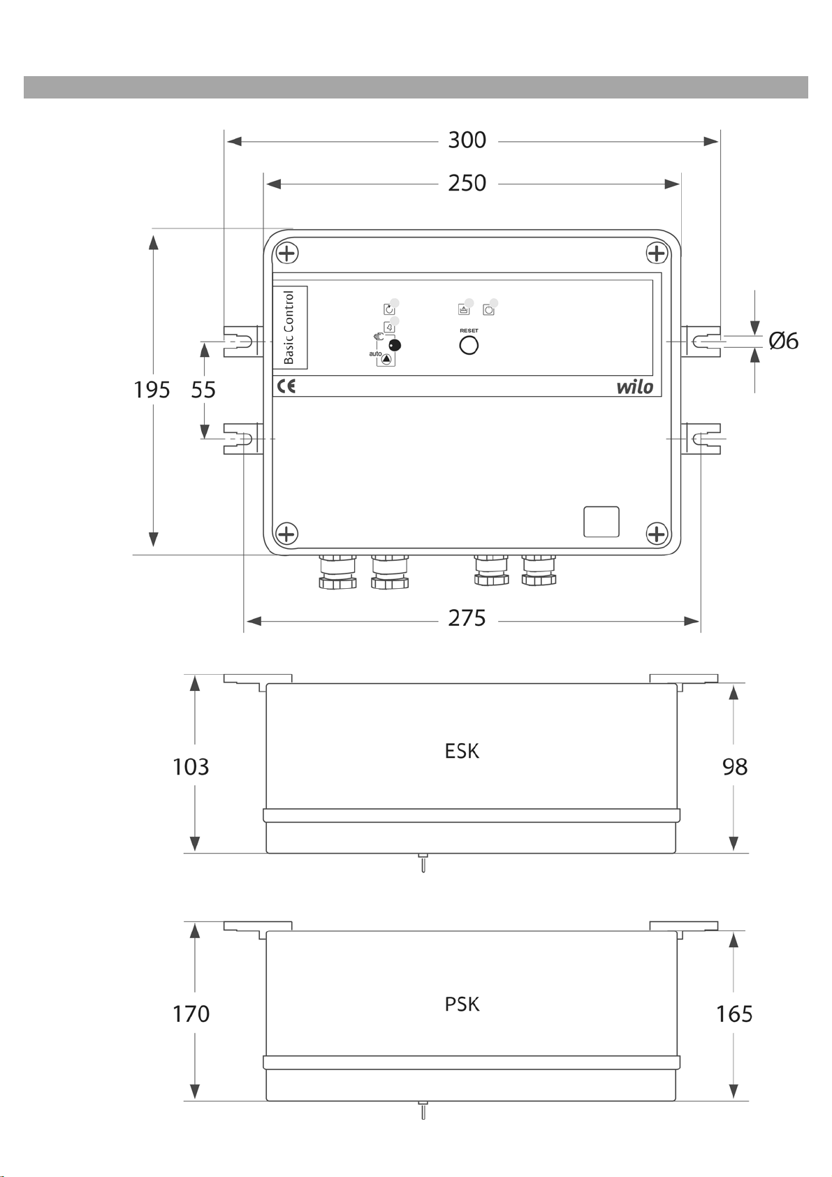
Fig. 3:
Page 4
Fig. 4a: Fig. 4b: Fig. 4c:
Fig. 4d: Fig. 4e:
Fig. 4f:
Page 5

English
1 General ..................................................................................................................................................11
2 Safety.....................................................................................................................................................11
2.1 Symbols and signal words in the operating instructions ................................................................................11
2.2 Personnel qualifications.......................................................................................................................................11
2.3 Danger in the event of non-observance of the safety instructions ..............................................................11
2.4 Safety consciousness on the job ........................................................................................................................ 11
2.5 Safety instructions for the operator .................................................................................................................12
2.6 Safety instructions for installation and maintenance work ...........................................................................12
2.7 Unauthorised modification and manufacture of spare parts ..........................................................................12
2.8 Improper use ........................................................................................................................................................12
3 Transport and interim storage ...........................................................................................................12
4 Intended use .........................................................................................................................................12
5 Product information ..........................................................................................................................13
5.1 Technical data ....................................................................................................................................................13
5.2 Scope of delivery .................................................................................................................................................. 13
5.3 Accessories (optional) .........................................................................................................................................13
6 Description ...........................................................................................................................................13
6.1 Front side of the switchgear ..............................................................................................................................13
6.2 Single components in the housing ................................................................................................................... 13
7 Installation and electrical connection ...............................................................................................14
7.1 Installation ............................................................................................................................................................14
7.2 Electrical connection ...........................................................................................................................................14
7.2.1 Connection of the pump engine .........................................................................................................................14
7.2.2 Connection of external elements ......................................................................................................................14
7.2.3 Mains connection .................................................................................................................................................14
8 Commissioning .....................................................................................................................................14
8.1 Selecting the operating mode ............................................................................................................................14
8.2 Settings and tests ................................................................................................................................................14
8.2.1 Overload protection ............................................................................................................................................14
8.2.2 Check direction of rotation (3-phase motor only) ..........................................................................................15
8.3 Selecting the operating mode ............................................................................................................................15
8.3.1 Installation with two electrodes ........................................................................................................................ 15
8.3.2 Installation with one electrode ..........................................................................................................................15
8.3.3 Installation with flow meter ...............................................................................................................................15
8.3.4 Pumping operation ..............................................................................................................................................15
8.3.5 Pressure boosting................................................................................................................................................. 16
9 Maintenance..........................................................................................................................................16
10 Faults, causes and remedies................................................................................................................16
11 Spare parts ............................................................................................................................................17
10 WILO SE 12/2015
Page 6

English
1 General information
About this document
The language of the original operating instructions is German. All other language versions are
translations of the original German manual.
These installation and operating instructions are
an integral part of the product. They must be kept
readily available at the place where the product is
installed. Strict adherence to these instructions is
a precondition for the proper use and correct
operation of the product.
These installation and operating instructions correspond to the relevant version of the product and
the underlying safety standards valid at the time
of going to print.
EC declaration of conformity:
A copy of the EC declaration of conformity is a
component of these operating instructions.
If a technical modification is made on the designs
named there without our agreement or the declarations made in the installation and operating
instructions on product/personnel safety are not
observed, this declaration loses its validity.
2Safety
These operating instructions contain basic information which must be adhered to during installation, operation and maintenance. For this reason,
these operating instructions must, without fail, be
read by the service technician and the responsible
specialist/operator before installation and commissioning.
It is not only the general safety instructions listed
under the main point “safety” that must be
adhered to but also the special safety instructions
with danger symbols included under the following
main points.
2.1 Symbols and signal words in the operating
instructions
Symbols:
General danger symbol
CAUTION!
There is a danger of damaging the product/unit.
‘Caution’ implies that damage to the product is
possible if this information is disregarded.
NOTE:
Useful information on handling the product. It
draws attention to possible problems.
Information that appears directly on the product,
such as:
• Direction of rotation arrow
• Identifiers for connections,
• Rating plate
• Warning sticker
must be strictly complied with and kept in legible
condition.
2.2 Personnel qualifications
The installation, operating and maintenance personnel must have the appropriate qualifications
for this work. Area of responsibility, terms of reference and monitoring of the personnel are to be
ensured by the operator. If the personnel are not in
possession of the necessary knowledge, they are
to be trained and instructed. This can be accomplished if necessary by the manufacturer of the
product at the request of the operator.
2.3 Danger in the event of non-observance of the
safety instructions
Non-observance of the safety instructions can
result in risk of injury to persons and damage to
the environment and the product/unit. Nonobservance of the safety instructions results in
the loss of any claims to damages.
In detail, non-observance can, for example, result
in the following risks:
• Danger to persons from electrical, mechanical and
bacteriological influences,
• Damage to the environment due to leakage of
hazardous materials
• Property damage
• Failure of important product/unit functions
• Failure of required maintenance and repair
procedures
Danger due to electrical voltage
NOTE
Signal words:
DANGER!
Acutely dangerous situation.
Non-observance results in death or the most
serious of injuries.
WARNING!
The user can suffer (serious) injuries. ‘Warning’
implies that (serious) injury to persons is probable if this information is disregarded.
Installation and operating instructions Wilo-Control ESK1, PSK1 11
2.4 Safety consciousness on the job
The safety instructions included in these installation and operating instructions, the existing
national regulations for accident prevention
together with any internal working, operating and
safety regulations of the operator are to be complied with.
Page 7

English
2.5 Safety instructions for the operator
This appliance is not intended for use by persons
(including children) with reduced physical, sensory
or mental capabilities, or lack of experience and
knowledge, unless they have been given supervision or instruction concerning use of the appliance
by a person responsible for their safety.
Children should be supervised to ensure that they
do not play with the appliance.
• If hot or cold components on the product/the unit
lead to hazards, measures must be taken onsite to
guard them against touching.
• Guards protecting against touching moving components (such as the coupling) must not be
removed whilst the product is in operation.
• Leakages (e.g. from the shaft seals) of hazardous
fluids (which are explosive, toxic or hot) must be
led away so that no danger to persons or to the
environment arises. National statutory provisions
are to be complied with.
• Highly flammable materials are always to be kept
at a safe distance from the product.
• Danger from electrical current must be eliminated.
Local directives or general directives [e.g. IEC, VDE
etc.] and instructions from local energy supply
companies must be adhered to.
2.6 Safety instructions for installation and
maintenance work
The operator must ensure that all installation and
maintenance work is carried out by authorised and
qualified personnel, who are sufficiently informed
from their own detailed study of the operating
instructions.
Work on the product/unit must only be carried out
when at a standstill. It is mandatory that the procedure described in the installation and operating
instructions for shutting down the product/unit
be complied with.
Immediately on conclusion of the work, all safety
and protective devices must be put back in position and/or recommissioned.
2.8 Improper use
The operating safety of the supplied product is
only guaranteed for conventional use in accordance with Section 4 of the operating instructions.
The limit values must on no account fall under
or exceed those specified in the catalogue/
data sheet.
3 Transport and interim storage
Immediately after receiving the product:
• Check the product for transport damage.
• In the event of damage in transit, take the necessary steps with the forwarding agent within the
respective time limits.
CAUTION! Risk of property damage!
Incorrect transport and interim storage can
cause damage to the product.
• The switchgear is to be protected against moisture and mechanical damage.
• It must not be exposed to temperatures outside
the range of -10 °C to +55 °C.
4 Intended use
Switchgear for use as an
• automatic control of single pumps
• Water level control
• Overload protection
• Dry-running protection
Fields of application using electrodes, float
switches and pressure switches.
No other devices for other purposes may be
installed in the switchgear.
Intended use includes compliance with this
manual.
Any other use is regarded as improper use.
2.7 Unauthorised modification and manufacture of
spare parts
Unauthorised modification and manufacture of
spare parts will impair the safety of the product/
personnel and will make void the manufacturer’s
declarations regarding safety.
Modifications to the product are only permissible
after consultation with the manufacturer. Original
spare parts and accessories authorised by the
manufacturer ensure safety. The use of other
parts will absolve us of liability for consequential
events.
12 WILO SE 12/2015
Page 8

5 Product information
5.1 Technical data
Mains supply voltages
Max. current consumption
Wilo-Control
— ESK1:
— PSK1:
Protection class:
Mains fuses
Control (230/400 V):
Low-voltage component:
Ambient temperature: -10 to +55 °C
1~ 230 V, 50/60 Hz
3~ 230 V, 50/60 Hz
3~ 400 V, 50/60 Hz
1-12 A
10-23 A
IP 54
0.1 A
0.8 A
English
5.2 Scope of delivery
• Switchgear
• Installation and operating instructions
• 2 electrodes
• 4 holders for installation of the switchgear
• Plastic clips and ribbons for the mounting of a
capacitor in the cover of the switchgear
(for version 1~230 V)
Item Element Function
1 Signal lamp - green lights up continuously when mains voltage is available
2 Signal lamp - yellow
Depends on the selected operating mode:
– Displays “low water status”
– Lower level reached
3 Signal lamp - red
Pump fault
4 Signal lamp - green
Pump in operation
5 Three-way switch
Operating mode
6 Pushbutton Resets the thermal overload protection
lights up continuously when the electrodes are triggered
lights up continuously when the pump is stopped due to an error.
lights up permanently while the pump is running
Selecting the operating mode:
AUTO Automatic operation with all safety functions,
0Off
MANU button function
5.3 Accessories (optional)
• Connection cable for electrodes
• External displays (clock, pressure gauge, etc.)
• Direction-of-rotation sensor
6Description
6.1 Front of the switchgear (Fig. 1)
electronic motor protection, low-water protection
6.2 Single components in the housing (Fig. 2)
Item Element
1 Thermo-magnetic circuit breaker
2 12 V transformer for low voltage part
3 Motor protection
4 Terminal strip for external sensors (electrode, pressure switch, float switch, external control)
5 Earth contact
6 Variable adjustment of rated motor power in accordance with pump motor rating plate
7 Variable adjustment of electrode sensitivity to the hardness of the water
8 Variable adjustment of time delay for “low water status” display
9 Variable adjustment of time delay for pressure switch/flow meter
10 Fuse (0.1 A) for pre-selected voltage in accordance with pump motor rating plate
11 Protection class selector switch for low water protection
12 On/off switch for time delay when using pressure switch or flow meter
13 Connector for control panel circuit board
14 Fuse holder low voltage fuse (0.8 A)
Installation and operating instructions Wilo-Control ESK1, PSK1 13
Page 9

English
7 Installation and electrical connection
7.1 Installation
Wall-mounted installation: Dimensions, see Fig. 3
7.2 Electrical connection (Fig. 4a-f)
DANGER! Risk of fatal injury!
When working on the open switchgear, there is
a danger of electric shock from touching the live
components.
Have the electrical connection established by an
electrician approved by the local electricity supply company only and in accordance with applicable regulations.
The current and voltage of the mains connection
must correspond to the details on the rating
plate of the pump to be connected / of the
motor.
• Adhere to regulations for accident prevention!
• Earth the pump/installation in accordance with
the regulations.
• Mains connection cable for three-phase:
4 x 1.5 mm², for single-phase: 3 x 1.5 mm².
• Remove the case cover.
• 0.1 A Insert fuse into the corresponding holders for
the used voltage: 230 V or 400 V (Fig. 2, item 10).
7.2.1 Connection of the pump motor (Fig. 2)
DANGER! Risk of fatal injury!
Poor earthing can lead to electric shock.
• Connect the earthing cable with the terminal
strip (Fig. 2, item 5)
7.2.3 Mains connection
DANGER! Risk of fatal injury!
Poor earthing can lead to electric shock.
• Connect the earthing cable with the terminal
strip (Fig. 2, item 5)
Three-phase 400 V (230 V):
Four-core cable (3 phases + earth) Ø 1.5 mm
terminals R-S-T.
Single-phase 230 V:
Three-core cable (1 phase + neutral + earth)
Ø 1.5 mm
2
to terminals L-N.
8 Commissioning
CAUTION! Risk of malfunctions!
If power consumption falls below 1 A during
operation, (idling power), reset the device by
pressing the 'RESET' button (Fig. 1, item 6).
8.1 Selecting the operating mode
A 3-way selector switch (button) is used to select
the operating mode on the front of the switchgear
(Fig. 1; item 5):
“MANU” (button) position: the system is manually controlled, regardless of the level setting or
external control components.
Position “0”: the pump cannot operate. It remains
deactivated in all circumstances.
Position “AUTO”: the pump operates automatically based on the selected system.
8.2 Settings and tests
2
to
Three-phase 400 V:
Four-core cable (3 phases + earth) on contact
(item 3) to terminals 2-4-6
Single-phase 230 V:
Three-core cable (1 phase + neutral + earth) on
contact (item 3) to terminals 2-4
7.2.2 Connect external elements
DANGER! Risk of fatal injury!
Poor earthing can lead to electric shock.
• Connect the earthing cable with the terminal
strip (Fig. 2, item 5)
• Do not connect an external voltage to terminal
strip (Fig. 2, item 4).
It is possible to perform remote control using an
external control element (pressure switch, control, level control, etc.). Connection via a two-core
cable Ø 0.75 mm
2
to the terminals 5 + 6 of the terminal strip (see Fig. 2; item 4); beforehand,
remove the bridge between terminals 5 + 6.
Connect the cable to the terminal strip based on
the intended application (see Fig. 2, item 4 and
Fig. 4;. see Chapter 6.3).
8.2.1 Overload protection
DANGER! Risk of fatal injury!
Make all settings when the pump is deactivated.
• Set the potentiometer (Fig. 2, item 6) to the rated
motor power specified on the rating plate (or for
submersible pumps, on the equipment label near
the switchgear).
• Set three-way switch (Fig. 1, item 5) to 'AUTO' the green signal lamp lights up and the pump
starts.
If the fault light comes on within 3 minutes, the
rated power is set too low.
• Before changing settings, check the motor
power consumption and the connections.
• Reset the rated power based on the determined
values.
14 WILO SE 12/2015
Page 10

English
8.2.2 Check direction of rotation
(3-phase motor only)
Keep three-way switch (Fig. 1, item 5) at the position 'MANU' (the 'Mains voltage' signal lamp lights
up). When there is a signal (float switch, electrode,
etc.), the pump starts.
For direction-of-rotation control, follow the
instructions for commissioning the pump.
If the direction of rotation is incorrect:
• Switch off the plant
• Switch two phases in the switchgear.
8.3 Selecting the operating mode
Depending on the application, an operating mode
must be set.
8.3.1 Installation with two electrodes (Fig. 4a)
• Select low-water protection (Fig. 2, item 11)
• Configure the sensitivity of the electrodes
Before the pump is started, set the water conductivity potentiometer (Fig. 2, item 7) to the minimum value.
Make sure that the electrodes are immersed and
the three-way switch (Fig. 1, item 5) is set to position 'AUTO'. Slowly turn the potentiometer (Fig. 2,
item 7) clockwise until the pump starts.
• Applying the electrodes
(see the pump operating instructions)
NOTE:
The lower electrode reports low water. The upper
electrode must be immersed in order to reset this
error.
8.3.2 Installation with one electrode (Fig. 4b)
CAUTION! Risk of malfunctions!
Select low-water protection (Fig. 2, item 11)!
• Configure the sensitivity of the electrode
Before the pump is started, set the water hardness
potentiometer (Fig. 2, item 7) to the minimum
value.
Make sure that the electrodes are immersed and
the three-way switch (Fig. 1, item 5) is set to position 'AUTO'. Slowly turn the potentiometer (Fig. 2,
item 7) clockwise until the yellow signal lamp
(Fig. 1, item 2) starts to flash.
• Set the time delay before restarting
After stopping due to low water, the pump will
start with a delay (1 to 30 minutes).
The delay is preset in the potentiometer (Fig. 2,
item 8).
During the waiting period, the yellow signal lamp
flashes (Fig. 1, item 2).
• Applying the electrode
(see the pump operating instructions)
8.3.3 Installation with flow meter (Fig. 4c)
CAUTION! Risk of malfunctions!
Set water hardness potentiometer to its maximum value (Fig. 2, item 7)!
• Select low-water protection (Fig. 2, item 11).
• Set the time delay before restarting
After stopping due to low flow rates, the pump will
start with a delay (1 to 30 minutes). This delay
allows for sufficient filling of the water tank
before a restart.
The delay is preset in the potentiometer (Fig. 2,
item 8).
During the waiting period, the yellow signal lamp
flashes (Fig. 1, item 2).
• Configure the time delay before a restart (Fig. 2,
item 9)
To provide the flow meter with enough time to
record a sufficient flow rate, a minimum period
operating time (5 seconds to 3 minutes) is configured for the pump. If the flow meter has not been
activated after this time has elapsed, the pump
will stop.
• Activating the time delay functions
(Fig. 2, item 12)
“AUT” position:
Both delays are active
“MAN” position:
The restart is triggered by pressing the 'Reset'
button (Fig. 1, item 6).
CAUTION! Risk of malfunctions!
Make sure that the bridge between terminals 5 + 6
on the terminal strip (Fig. 2, item 4) is correctly
positioned.
8.3.4 Pumping operation
CAUTION! Risk of malfunctions!
Set water conductivity potentiometer to its
maximum value (Fig. 2, item 7)!
Operation with one float switch (Fig. 4d)
• Select low-water protection (Fig. 2, item 11).
In this position, the float switch is connected to
terminals 5 + 6 of the terminal strip (Fig. 2, item 4).
• Connect a protection switch (as dry running protection) to terminals 1 + 3 of the terminal strip.
• Set the time delay before restarting
After stopping due to low water, the pump will
start with a delay (1 to 30 minutes).
The delay is preset in the potentiometer (Fig. 2,
item 8).
During the waiting period, the yellow signal lamp
flashes (Fig. 1, item 2).
Installation and operating instructions Wilo-Control ESK1, PSK1 15
Page 11

English
Operation with two float switches (Fig. 4e)
• Select low-water protection (Fig. 2, item 11).
In this position, the device only activates the
pump and the yellow signal lamp (Fig. 1, item 2)
displays the filling phase.
CAUTION! Risk of malfunctions!
Make sure that the bridge between terminals 5 + 6
on the terminal strip (Fig. 2, item 4) is correctly
positioned.
8.3.5 Pressure boosting (Fig. 4f)
CAUTION! Risk of malfunctions!
Set water hardness potentiometer to its
maximum value (Fig. 2, item 7)!
Float switch in the tank + pressure switch
• Select low-water protection (Fig. 2, item 11).
In this position, the pressure switch is connected
to terminals 5 + 6 of the terminal strip (Fig. 2,
item 4).
• Set the time delay before restarting
After stopping due to low water, the pump will
start with a delay (1 to 30 minutes).
The delay is preset in the potentiometer (Fig. 2,
item 8).
During the waiting period, the yellow signal lamp
flashes (Fig. 1, item 2).
Pressure switch in the inlet pipe + pressure
switch
• Select low-water protection (Fig. 2, item 11).
In this position, the pressure switch is connected to
terminals 5 + 6 of the terminal strip (Fig. 2, item 4).
• Set the time delay before restarting
After stopping due to low water, the pump will
start with a delay (1 to 30 minutes).
The delay is preset in the potentiometer (Fig. 2,
item 8).
During the waiting period, the yellow signal lamp
flashes (Fig. 1, item 2).
9 Maintenance
DANGER! Risk of fatal injury!
When working on the open switchgear, there is
a danger of electric shock from touching the live
components.
• Before maintenance and repair work, disconnect
the system from the power supply and make
sure it cannot be switched on by unauthorised
persons.
10 Faults, causes and remedies
Have faults remedied by qualified personnel
only! Follow the safety instructions in
Chapter “Safety”!
Fault Causes Remedy
The pump does not start or constantly
stops working
Pump fault at pump start)
Pump fault
Continuous fault indication
Faulty automation
The pump starts up but the flow rate is
too low
• Faulty mains connection
• The fuse for the pre-selected voltage
(Fig. 2, item 11) has been inserted
incorrectly or is defective
• Operating mode in position '0'
• The circuit for external control has
been interrupted
• No electrodes, float switches or
bridges are connected
• Contactor problem
• Faulty cabling/wiring
• Thermal protection switch (Fig. 2,
item 1) triggered
• Faulty earthing connection
• Exceptionally soft water
• Time delay set to '0'
• The rotation speed is too low
• Incorrect direction of rotation
• Reconnect a mains connection with
the appropriate available voltage.
• Insert fuse into the correct holder. If
necessary, replace the fuse.
• Place the switch (Fig. 1, item 5) into
position 'AUTO'.
• Close the circuit or check for presence
of the bridge (terminals 5 + 6 of the
terminal strip)
• Connect electrodes, float switch or
bridge, depending on the application
(Figs. 4a-f)
• Check relays.
• Check cabling/wiring.
• Check whether the configured rating
matches the rating specified on the
motor rating plate.
• Reset the fault using the “RESET”
switch.
If the fault remains, contact the
Service contact.
• Check the earthing connections and
mass contacts of the pump
• Check setting (see § 6.3.1.1).
• Check the operation and setting of
time delay.
• Check the power supply and motor
connection.
• Switch two phases!
16 WILO SE 12/2015
Page 12

11 Spare parts
All spare parts must be ordered directly from the
Wilo customer service.
To avoid queries and incorrect orders, all data from
the rating plate must be specified with every
order.
The spare parts catalogue can be found at the
following address: www.wilo.com.
Subject to change without prior notice.
English
Installation and operating instructions Wilo-Control ESK1, PSK1 17
Page 13

Page 14

3LRQHHULQJIRU<RX
:,/26(
1RUWNLUFKHQVWUDH
''RUWPXQG
*HUPDQ\
7
)
ZLOR#ZLORFRP
ZZZZLORFRP
 Loading...