

Page 1
MODELS INCLUDED
• RU-150
• RU-225
• RU-300
• RU-600
• RU-1000
CAUTION: Please use
this setup procedure
before attempting to use
this brewer. Failure to follow the
instructions can result in injury or the
voiding of the warranty.
WARNING: DO NOT
place this urn closer than
six [6] inches from wall.
Urn must have adequate
cross-ventilation.
CAUTION: DO NOT
connect this urn to hot
water. The inlet valve is
not rated for hot water.
WARNING When you
hookup an electric urn,
use the proper wire gauge,
plus 25%. Never use fuses
or breakers larger than needed. The
body of the urn must be securely
grounded with a separate grounding
conductor and never with the neutral
conductor of a single phase, 3 wire
system.
Refer to the wiring diagram included
with each urn for wire gauge.
Wilbur Curtis Company, inC.
Service Manual – RU Series Automatic Urns
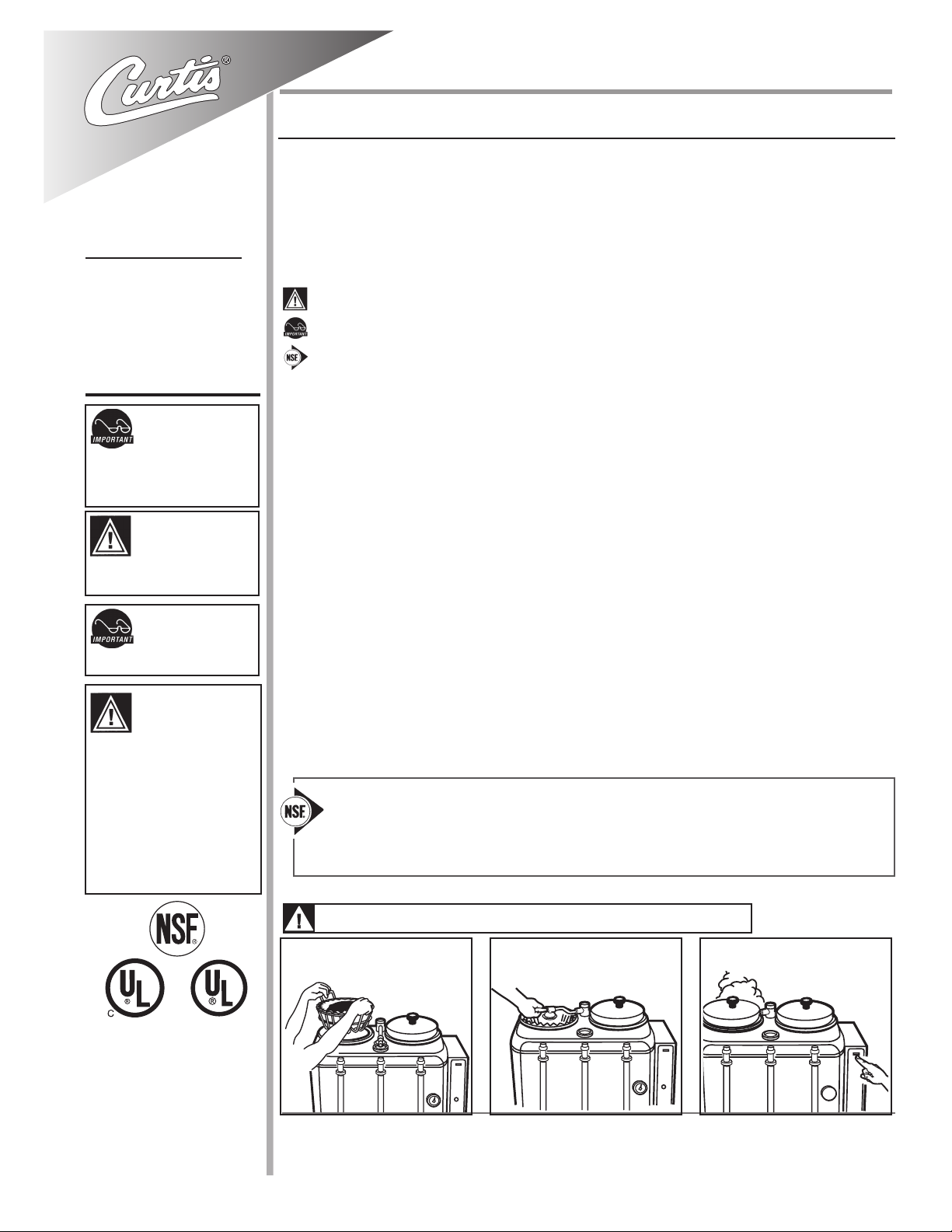
Important Safeguards/Symbols
This equipment is designed for commercial use. Any servicing other than cleaning and routine maintenance should be performed by an
authorized Wilbur Curtis Company Service Technician.
• DO NOT immerse the unit in water or any other liquid
• To reduce the risk of re or electric shock, DO NOT open service panels. There are no user serviceable parts inside.
• Keep hands and other items away from hot areas of the unit during operation.
• Never clean with scouring powders or harsh chemicals.
Symbols
WARNINGS – To help avoid personal injury
Important Notes/Cautions – from the factory
Sanitation Requirements
The RU Automatic Urn is Factory Pre-Set and Ready to Go… Right from the Box.
Factory Settings:
• Brew Temperature = 200°F • Brew Volume = Set to requirements of coffee liner.
System Requirements
• Water Source: 20 – 100PSI (Min Flow Rate of 1 GPM)
• Electrical: See attached schematic for standard model or visit www.wilburcurtis.com for your model.
• HEAT SUPPLY: Read the serial tag to determine the energy source (electric, gas, steam).
SETUP STEPS
1. Place unit at counter height. on a rm, level base, in such a way that it can be connected to water and power supply.
2. Install the water and coffee faucet.
3. Connect water line to inlet tting on valve. It is recommended that some type of water mineral reducing lter be used in the water
line before entering the unit. Water pressure entering brewer is required to be stable and must provide minimum of 1 gallon per
minute. Use water regulator for constant pressure. Required water pressures, 20 to 100 psi. Turn on water valve.
4. If setting up a gas urn, connect gas line with 3/8” O.D. ex tube from urn to gas valve in the facility. Check for leaks.
5. Hook-up electrical power to the unit (refer to schematic for power requirements). If gas or steam, 120V circuit is required.
6. When power is turned on, water will start owing into the water jacket. You may increase the speed of the lling by using the
emergency rell valve.
7. When the water jacket has lled, turn on the thermostat by turning the dial clockwise to the desired setting. It will take 50 to 60
minutes for the heating tank to reach operating temperature. On electric urns, the thermostat indicator will light at this time.
NSF International requires the following:
1. A quick disconnect or additional coiled tubing (at least 2x the depth of the unit) so the unit can be moved for cleaning.
2. This equipment is to be installed with adequate backow protection to comply with applicable federal, state and local
codes.
3. Water pipe connections and xtures directly connected to a portable water supply shall be sized, installed and maintained in accordance with federal, state, and local codes.
ISO 9001:2008 REGISTERED
WILBUR CURTIS CO., INC.
6913 West Acco Street
Montebello, CA 90640-5403
For the latest information go to
www.wilburcurtis.com
Tel: 800-421-6150
Fax: 323-837-2410
BREWING INSTRUCTIONS
WARNING HOT LIQUID, Scalding may occur. Avoid splashing.
1. Place lter in basket. Pour coffee into
lter. Place basket into liner.
For the latest specications and information go to www.wilburcurtis.com
Technical Support: 1-800-995-0417 M-F 5:30am-4:00pm PT
2. Rotate sprayhead over bed of coffee
inside lter.
Email: techsupport@wilburcurtis.com
3. Press the BREW button on control
panel to begin brewing.
Page 2
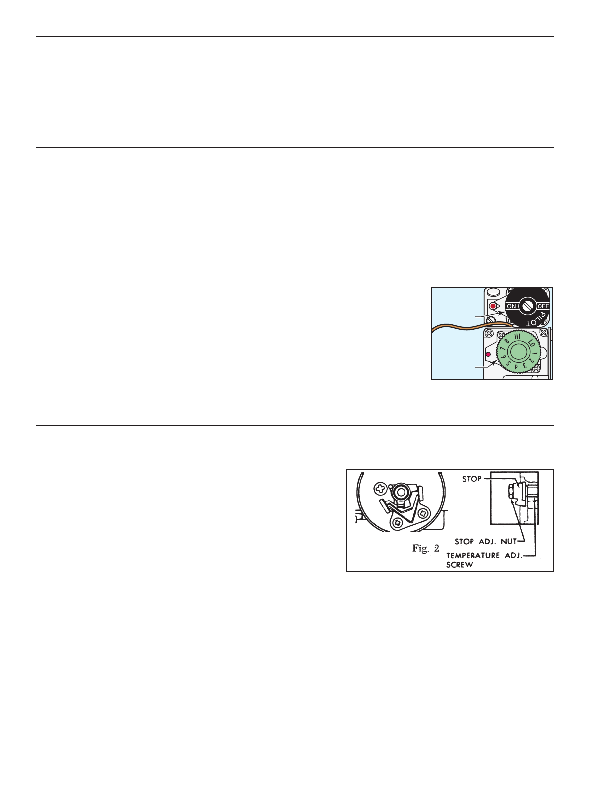
Fig 1. Dial on the gas thermostat
set at 6½.
PILOT
DIAL
THERMOSTAT
DIAL
ELECTRIC THERMOSTAT ADJUSTMENT
On electric urns, thermostats are set at the factory to cut off at 200ºF. We do not recommend changing this. If necessary, adjustment is as follows:
1. Rotate the thermostat knob to the right to the BOIL position. Remove the knob by pulling off from the stem.
2. Locate the tiny adjustment screw, inside the stem (see gure 1). Using a small screwdriver, adjust the temperature up or down:
a. By turning the screw ¼ turn to the left will increase the temperature about 20°F.
b. Turning ¼ to the right will decrease the temperature by 20°F.
c. To set the thermostat precisely at 200°F, insert a thermometer probe into the water jacket through the steam hole (just under the sprayhead). Turn the screw ½ turn to the left.
When the thermometer reaches 200°F, slowly turn the adjustment screw to the right until the pilot light turns off.
GAS URN INSTALLATION
The urn must be away from wall no less than 6” and must have plenty of cross ventilation.
The water supply connection is the same in all RU models. All that is needed is 1/4” copper tubing with a 1/4” are nut and some sort of water lter in the line before water enters
the unit. Once the water connection is complete, open the water line, then plug in the power cord into an 115V outlet. To facilitate the lling of the water jacket, you can open the
emergency rell faucet (red knob) behind the unit, to increase the speed of lling the urn. Water must be above the base of the center gauge glass before turning on the heat.
GAS CONNECTION
All RU automatic urns are supplied with a 3/8” pressure connector at the end of the gas valve. This valve is connected to the thermostat. Use 3/8” O.D. stainless steel ex tubing to
make the connection from the urn to the gas valve in your facility. When the connections are complete, turn the gas on. Check the line for leaks.
PROCEDURE FOR LIGHTING OR RELIGHTING PILOT
1. Remove the pilot control cover on the right side of the thermostat cover (held in place by four screws).
2. Turn the pilot dial to the OFF position and thermostat dial to the lowest temperature position.
3. Allow sufcient time for any gas that may still be in the burner compartment to dissipate.
4. Push in the pilot dial (the dial has a slight inward travel) and rotate it to the PILOT position. On older units, there is a separate red
SET button that must be pushed in to allow the dial to turn.
5. Continue pressing in the dial while lighting the pilot burner. The pilot is located inside the burner compartment, between the main
burners.
6. Once lit, allow the ame to burn for approximately 30 seconds before releasing pilot dial. If the pilot ame does not remain lit,
repeat the operation, allowing for a longer period before releasing the pilot dial.
7. Turn the pilot dial to the ON position. Turn the thermostat dial to the desired position. The main burner will then ignite.
MAIN BURNER ADJUSTMENT
To adjust the main burner ame, turn the thermostat dial to 6½ for 195ºF or 7 for 200ºF; see gure 1. For older units (made before serial number 12327781), turn the screw under the gas cock handle in either direction to regulate the ow of gas to the main burner.
TO RE-CALIBRATE THE THERMOSTAT
The Unitrol thermostat is built to the most exacting standards and is a precision instrument which should never need re-calibration. However because of tampering, misuse or
other reason, if the thermostat is found to be more than 10º from normal, a re-calibration may be performed by a qualied service technician. The following are the steps for this
procedure:
1. Turn the thermostat to OFF to allow the unit to cool down.
2. When the water temperature is room temperature, turn the thermostat dial until the main burner
ignites.
3. Slowly, turn the thermostat dial counterclockwise until the ame on the burner goes out.
4. Place a thermometer into the water jacket to determine the temperature of the water.
5. Pull off the thermostat dial and lift off the outside cover.
6. Turn the temperature stop to correspond to the actual water temperature. Mark the location of the stop
for reference.
7. Turn the stop slowly until the control snaps off. Holding the stop to prevent rotation, carefully loosen
the stop adjustment nut (see gure 2).
8. Taking care not to move the temperature adjusting screw, turn the stop until it lines up with the tick mark (see step 6).
9. Hold the stop in place and tighten the stop adjustment nut.
10. Recheck the OFF temperature.
11. Replace the outside cover and thermostat dial.
THERMOCOUPLE CONNECTION
Poor contact between the thermocouple lead and the magnet assembly may cause the valve to be inoperative even when the pilot is in proper adjustment and position. If this is the
problem, clean and tighten the contact points. Remove the thermocouple and carefully clean the parts that make contact with the magnet assembly.
PROCEDURE FOR ADJUSTING PILOT
1. Remove pilot adjustment cap. Adjust pilot key, allowing ame to completely envelop the end ( ⅛”) of the thermocouple.
2. Adjust pilot burner air shutter (if provided) to obtain a soft blue ame.
2
Page 3
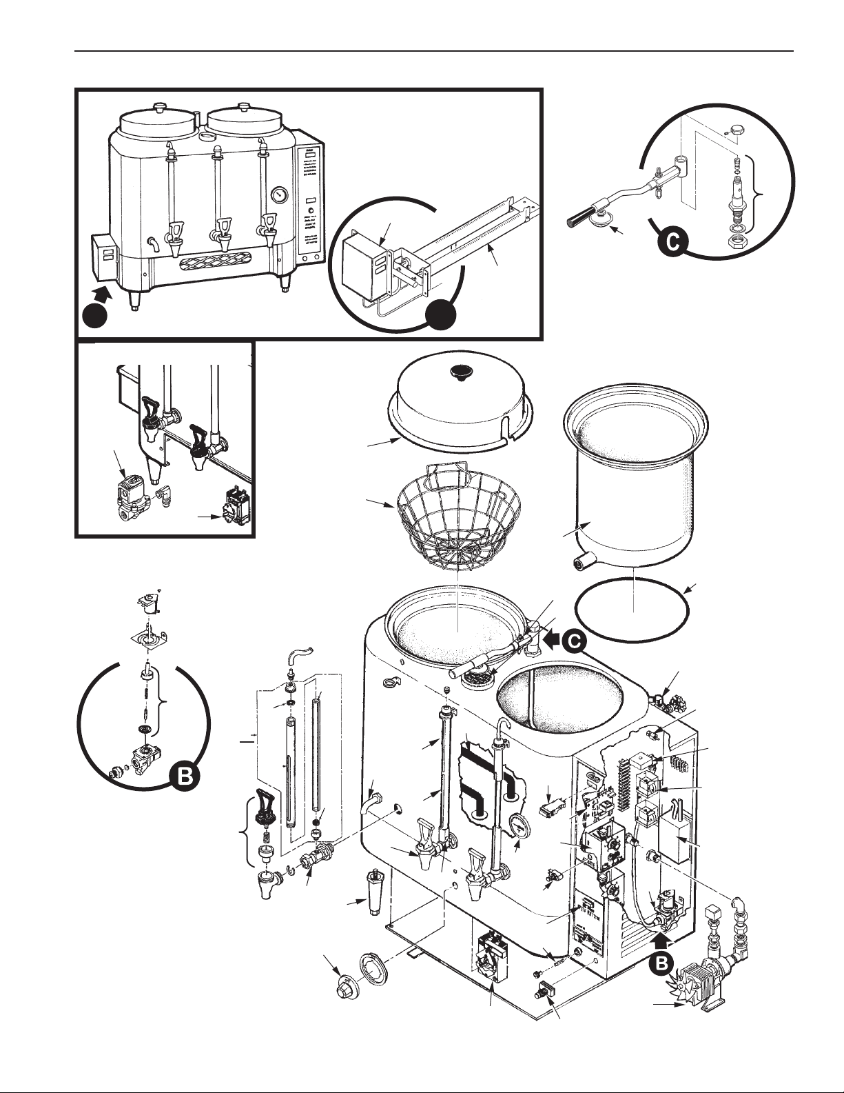
Illustrated Parts List - RU Automatic Urns
Gas Urn with Detail of
Burner Assembly
7
36
39
35
A
Steam Urn with Thermostat and
Valve
37
38
6
29
28
32
27
21
30
31
22
A
1
2
3
4
33
42
8
9
34
10
11
16
23
26
24
25
41
12
13
14
40
5
15
12
19
20
18
17
3
Page 4

Illustrated Parts List - RU Automatic Urns
1
1A
2
2A
2B
3
3A
3B
3C
3D
4*
4A
5
6
7
8
9
10
11
11A
12
13
14
15
16
17
18
19*
20*
21
22
23
24
24A
24B
24C
25
26
27
28
28A
29
29A
29B
29C
30
30A
30B
30C
30D
31
32
33
33A
34
35
35A
36
36A
37
38
39
40
41
42
WC-5601
WC-5603
WC-3302
WC-3303
WC-3304
WC-5700
WC-5702
WC-5706
WC-5704
WC-5708
WC-4303*
WC-43076
WC- 801 *
WC-3700*
WC-3753*
WC- 806*
WC-5502-01*
WC- 405R*
WC- 402*
WC- 403
WC-3737*
WC- 608*
WC- 600*
WC- 101*
WC-37166*
WC-1037*
WC- 100*
WC-1500*
WC- 501*
WC-3217
WC-3528
WC-2913
WC-2104*
WC-2105*
WC-2108*
WC-2113*
WC-2030*
WC-1800L*
WC-1901A
WC-3705*
WC-3705L
WC-2105*
WC-2107*
WC-2109*
WC-2114*
WC-2027*
WC-2028*
WC-2029*
WC-2031*
WC-2037*
WC-2006*
WC-2005*
WC-2908
WC-2909
WC-1109N
WC-1110N
WC-1141
WC-1141P
WC- 513
WC- 512
WC-2907
WC- 511
WC-1900
WC-5800
* SUGGESTED PARTS
DESCRIPTIONPART NºITEM
LID ASSY, LINER RU-150, RU-300
LID ASSY, LINER RU-225, RU-600, RU-1000
BASKET, WIRE W/FLAPS RU-300
BASKET, WIRE W/FLAPS RU-600
BASKET, WIRE W/FLAPS RU-1000
LINER, 3 GALLON RU-150
LINER, 6 GALLON RU-225
LINER, 6 GALLON RU-600
LINER, 3 GALLON RU-300
LINER, 10 GALLON RU-1000
O-RING, LINER RU-150, RU-300
O-RING, LINER, RU-225, RU-600, RU-1000
VALVE, INLET BRASS .50 GPM 120V 10W RU/WB
KIT, INLET VALVE REPAIR USE ON WC-890
KIT, VALVE CORE REPLACEMENT O-RING STYLE VALVE ¼”
GATE PLATED EMERGENCY REFILL
PROBE ASSY, WATER LEVEL W/HEX, O’RING & NUT
TIMER, AGITATION 120V 50/60HZ W/WIRES, BRKT
RELAY, HOLDING 120V COIL 10A (RU-150-600)
RELAY, 120V 3 POLE 6.6A RES @ 240V (RU-1000)
KIT, BREW SWITCH/INDICATOR LIGHT 120V
LEVEL CONTROL, WATER 120V
TIMER, BREW 8 MINUTE
SWITCH, ON/OFF NON-LIT SPST MOMENTARY 3/6A
KIT, AIR PUMP RU’S
WATER PUMP W/FITTINGS 120VAC
SWITCH, RESET/STOP NC NON-LIT S.P. MOMENT
FUSE, 5 AMP 5/PKG
THERMOSTAT, DPST CAPILLARY 277V 30A, 1 PH
KNOB, ELECTRIC THERMOSTAT
LEG, 4” ADJUSTABLE 3/8-16 THRD ITALIAN
SPOUT, OVERFLOW
GAUGE GLASS ASSY, 10” WATER RU-150
GAUGE GLASS ASSY, 11” WATER RU-300
GAUGE GLASS ASSY, 13” WATER RU-225/600
GAUGE GLASS ASSY, 19” WATER RU-1000
GLASS GAUGE, 13” WATER
FAUCET, S SERIES LOCKING 1-1/32-4 UNS
SHANK, FAUCET W/SHIELD BASE
KIT, FAUCET S SERIES NON-LOCK USE ON WC-1800
KIT, FAUCET S SERIES LOCKING
GAUGE GLASS ASSY, 11” RU-150
GAUGE GLASS ASSY, 12” RU-300
GAUGE GLASS ASSY, 14” RU-225 & RU-600
GAUGE GLASS ASSY, 20” COFFEE RU-1000
GLASS GAUGE 10”
GLASS GAUGE, 5/8”D X 11” RU-150
GLASS GAUGE, 5/8”D X 12” RU-300
GLASS GAUGE, 5/8”D X 14” RU-225 & RU-600
GLASS GAUGE, 5/8”D X 20” RU-1000
WASHER, .188 ID X .188 THK BOTTOM GAGE GLS
WASHER, 1/8” SHIELD CAP
SPRAYARM ASSY, RU-150 & RU-300
SPRAYARM ASSY, RU-225, RU-600 & RU-1000
HEATING ELEMENT - SEE ELECTRICAL DATA, PAGE 5
GAS BURNER ASSY, 23” NG RU-300, RU-600, RU-1000
GAS BURNER ASSY, 16” NG RU-150 & RU-225
KIT, CONTROL GAS URN
KIT, CONTROL PROPANE GAS RU
VALVE, STEAM 120V, 60Hz
THERMOSTAT, ELECT STEAM URNS
SPRAYHEAD ASSEMBLY
THERMOMETER, DIAL URNS
VALVE, GAUGE SHIELD SHUT-OFF
STEAM RING, URNS
4
Page 5

ELECTRICAL
DATA
MODEL
RU-150 -12
RU-150 -20
220
208/220
PHASE
1
3
WIRESVOLTS
3W + GND
3W OR 4W + GND
WATTS AMPS
5 KW
5.25 KW
23
15
1 - WC-913 -01 220V, 5 KW
ELEMENTS
1 - WC-907 -01 220V, 1.75 KW LEFT
1 - WC-907 -02 220V, 1.75 KW CENTER
1 - WC-907 -03 220V, 1.75 KW RIGHT
RU-225 -12
RU-225 -20
RU-300 -12
RU-300 -28
RU-300 -20
RU-600 -12
RU-600 -28
RU-600 -20
RU-1000 -12
RU-1000 -20
220
208/220
220
220
208/220
220
208/220
208/220
220
208/220
1
3
1
1
3
1
1
3
1
3
3W + GND
3W OR 4W + GND
3W + GND
3W + GND
3W OR 4W + GND
3W + GND
3W + GND
3W OR 4W + GND
3W + GND
3W OR 4W + GND
7 KW
7.5 KW
6 KW
8 KW
7.5 KW
10 KW
8 KW
10.5 KW
10 KW
10.5 KW
32
1 - WC-911 -01 220V, 3.5 KW
1 - WC-911 -02 220V, 3.5 KW
21
1 - WC-908 -01 220V, 2.5 KW LEFT
1 - WC-908 -02 220V, 2.5 KW CENTER
1 - WC-908 -03 220V, 2.5 KW RIGHT
27
2 - WC-910 220V, 3 KW
36
2 - WC-912 220V, 4 KW EA.
21
3 - WC-908 220V, 2.5 KW EA.
46
2 - WC-913 220V, 5 KW EA.
38
2 - WC-912 220V, 4 KW EA.
29
3 - WC-911 220V, 3.5 KW EA.
46
2 - WC-913 220V, 5 KW EA.
29
3 - WC-911 220V, 3.5 KW EA.
5
Page 6

Product Warranty Information
The Wilbur Curtis Company certies that its products are free from defects in material and workmanship under normal use. The following limited
warranties and conditions apply:
3 Years, Parts and Labor, from Original Date of Purchase on digital control boards.
2 Years, Parts, from Original Date of Purchase on all other electrical components, ttings and tubing.
1 Year, Labor, from Original Date of Purchase on all electrical components, ttings and tubing.
Additionally, the Wilbur Curtis Company warrants its Grinding Burrs for Forty (40) months from date of purchase or 40,000 pounds of coffee,
whichever comes rst. Stainless Steel components are warranted for two (2) years from date of purchase against leaking or pitting and replacement parts are warranted for ninety (90) days from date of purchase or for the remainder of the limited warranty period of the equipment in which
the component is installed.
All in-warranty service calls must have prior authorization. For Authorization, call the Technical Support Department at 1-800-995-0417. Effective
date of this policy is April 1, 2003.
Additional conditions may apply. Go to www.wilburcurtis.com to view the full product warranty information.
CONDITIONS & EXCEPTIONS
The warranty covers original equipment at time of purchase only. The Wilbur Curtis Company, Inc., assumes no responsibility for substitute replacement parts installed on Curtis equipment that have not been purchased from the
Wilbur Curtis Company, Inc. The Wilbur Curtis Company will not accept any responsibility if the following conditions are not met. The warranty
does not cover and is void under the following circumstances:
1) Improper operation of equipment: The equipment must be used for its designed and intended purpose and function.
2) Improper installation of equipment: This equipment must be installed by a professional technician and must comply with all local electrical,
mechanical and plumbing codes.
3) Improper voltage: Equipment must be installed at the voltage stated on the serial plate supplied with this equipment.
4) Improper water supply: This includes, but is not limited to, excessive or low water pressure, and inadequate or uctuating water ow rate.
5) Adjustments and cleaning: The resetting of safety thermostats and circuit breakers, programming and temperature adjustments are the
responsibility of the equipment owner. The owner is responsible for proper cleaning and regular maintenance of this equipment.
6) Damaged in transit: Equipment damaged in transit is the responsibility of the freight company and a claim should be made with the carrier.
7) Abuse or neglect (including failure to periodically clean or remove lime accumulations): Manufacturer is not responsible for variation
in equipment operation due to excessive lime or local water conditions. The equipment must be maintained according to the manufacturer’s
recommendations.
8) Replacement of items subject to normal use and wear: This shall include, but is not limited to, light bulbs, shear disks, “0” rings, gaskets,
silicone tube, canister assemblies, whipper chambers and plates, mixing bowls, agitation assemblies and whipper propellers.
9) Repairs and/or Replacements are subject to our decision that the workmanship or parts were faulty and the defects showed up under normal
use. All labor shall be performed during regular working hours. Overtime charges are the responsibility of the owner. Charges incurred by
delays, waiting time, or operating restrictions that hinder the service technician’s ability to perform service is the responsibility of the owner
of the equipment. This includes institutional and correctional facilities. The Wilbur Curtis Company will allow up to 100 miles, round trip, per
in-warranty service call.
RETURN MERCHANDISE AUTHORIZATION: All claims under this warranty must be submitted to the Wilbur Curtis Company Technical
Support Department prior to performing any repair work or return of this equipment to the factory. All returned equipment must be repackaged
properly in the original carton. No units will be accepted if they are damaged in transit due to improper packaging. NO UNITS OR PARTS WILL
BE ACCEPTED WITHOUT A RETURN MERCHANDISE AUTHORIZATION (RMA). RMA NUMBER MUST BE MARKED ON THE CARTON
OR SHIPPING LABEL. All in-warranty service calls must be performed by an authorized service agent. Call the Wilbur Curtis Technical Sup-
port Department to nd an agent near you.
7/18/11 . 14.8 . ECN 13345 . revE
5/18/11 . 13.4 . ECN 13186 . revD
8/8/8 . 14.8 . ECN 9894 . rev C
12/4/7 . 10.4 . ECN 9411 . rev B
11/1/07 . 15.0 . ECN 9351 . rev A
3/22/03 . 13.2 . EDR 3306 Rev NC
6
WILBUR CURTIS CO., INC.
6913 Acco St., Montebello, CA 90640-5403 USA
Phone: 800/421-6150 Fax: 323-837-2410
Technical Support Phone: 800/995-0417 (M-F 5:30A - 4:00P PST) E-Mail: techsupport@wilburcurtis.com
Web Site: www.wilburcurtis.com
FOR THE LATEST SPECIFICATION INFORMATION GO TO WWW.WILBURCURTIS.COM
Printed in U.S.A. 7/11 F-1950-S Rev E
 Loading...