

Page 1
CAUTION:
DO NOT
connect this brewer to hot
water. The inlet valve is
not rated for ho
t wa
ter.
FIND OUT MORE
Models Included
MWMGT-10
MWMGT-12
CAUTION:
Please use
this setup procedure
before attempting to use
this brewer. Failure to follow the
instructions
can result in injury or the
voiding of the
warranty.
Important Safeguards/Conventions
FOR THE LATEST SPECIFICATIONS AND INFORMATION GO TO WWW.WILBURCURTIS.COM
by an authorized Wilbur Curtis service center.
inside. Repair should be done only by authorized service personnel.
•
Keep hands and other items away from hot parts of unit during operation.
Never clean with scouring powders, bleach or harsh implements.
Important Notes/Cautions – from the factory
Sanitation Requirements
Following are the Factory Settings for your Mercury™ GT
• Brew Volume = 3 Gallon, 6 Gallon, 10 Gallon
adjustments to meet your brewing needs, programming instructions are provided later in this
manual.
• Horizontal wall space of 57 inches and vertical clearance of 84 inches.
• Electrical Service: 208 or 240 VAC Three Phase, 3 Wire Plus Ground, 50 Amp.
• Duplex outlet: 115 VAC, 20 Amp, immediate area of installation.
• Water connection: Minimum 3/8” O.D. tube for lengths less than 6¾”. Otherwise 1/2” O.D. tube with gate or ball
shut off valve at the supply pipe. Minimum fl ow rate of 1 GPM.
SYSTEM REQUIREMENTS
SETUP STEPS
2. Mounting holes are provided on both top and lower fl anges of the rear panel, 1/4” or 5/16” lag screws or toggle
bolts may be used depending on the wall structure.
3. It is essential that the Wall Mount unit (MWMGT) be positioned so that the center line of the bottom screw holes are
exactly 33¼” from the fl oor. This measurement is critical and will allow the wall unit to properly mate with the
coffee vessel..
4. Once mounted, the access plate, left side of the machine, must be removed to make the electrical connections.
Remove the four screws attaching the access plate to the wrap. Remove the plate to reveal the wiring connections
to the power block.
5. A qualifi ed electrician should make the electrical connections using #8 wire. The connection block is located on the
left rear of the frame with cable access through the bottom.
manual shut-off valve and a good water fi lter be installed in the water line close to the wall unit.
8. Place the hot water delivery tube assembly on the pipe extending from the top of the wall mounted unit. Press
down, gently guiding the swivel fi tting through the grommet in the top panel and further until it bottoms out.
Wrap the control cable once around the swivel fi tting in the direction of the ¼” O.D. conduit and press the plug
into the receptacle.
9. Mount the coffee vessel over the positioning lugs, located on top of push cart, with the faucet squarely over the
drip tray. Insert the knobbed anchor bolt into the hole underneath the table
top and thread it into the coffee vessel
bottom. Tighten securely.
NOTE:
Some type of wa-
ter fi ltration device must
be used to maintain a
trouble-free operation.
(In areas with extremely hard wa-
ter, we suggest that a sedimentary
and taste & odor fi lter be installed.)
This will prolong the life of your
brewing system and enhance
coffee quality.
approved backfl ow prevention
device may be required between
the brewer
and water supply.
WILBUR CURTIS COMPANY
Page 2
affi xed to the wall, the cart will be aligned to allow for the mating of the wall unit with the
vessel.
2. Nest the fi lter paper into the brew basket and add appropriate ground coffee for the
anticipated brew selection.
3. With the fi lter brew basket in place and with the coffee vessel cover positioned, insert the
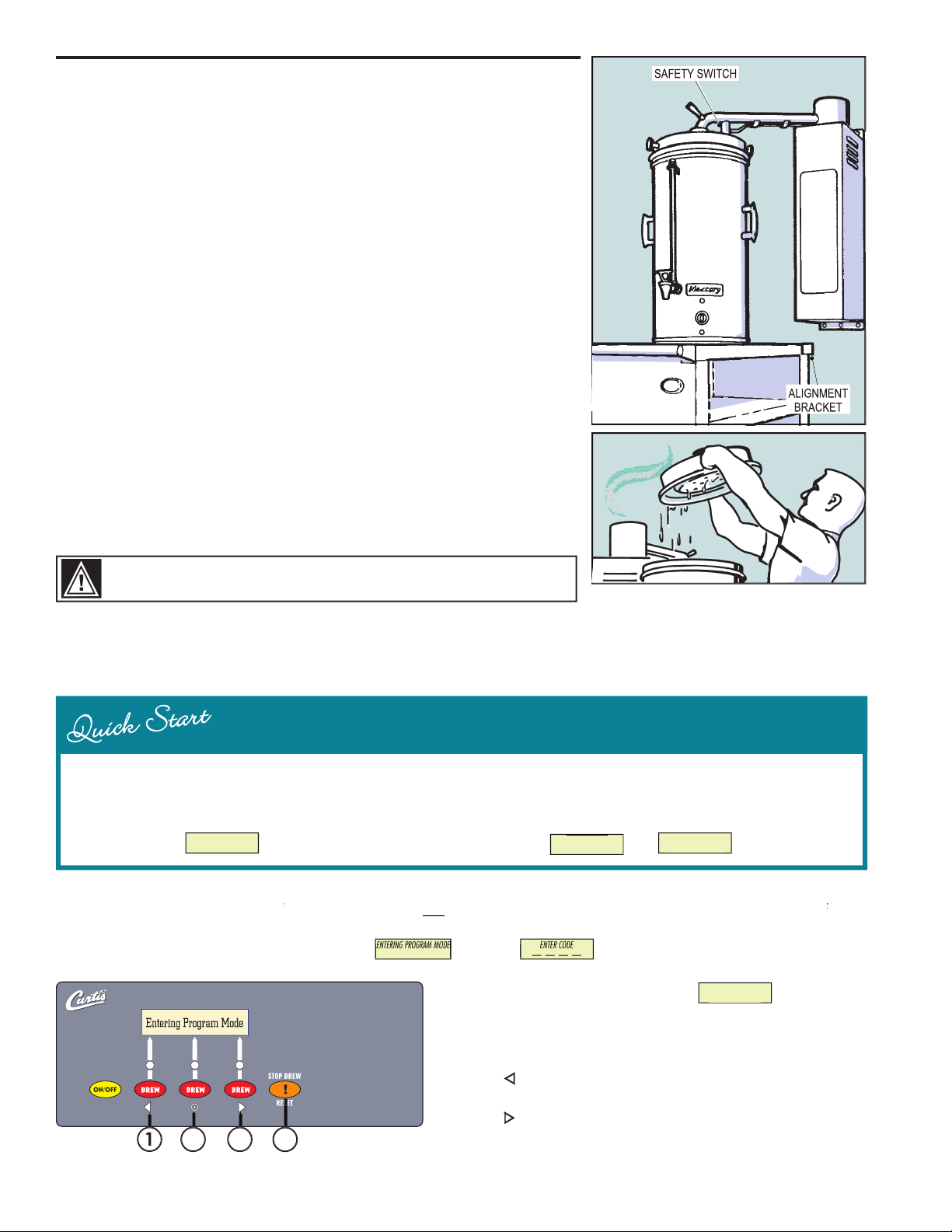
hot water delivery tube into the center receptacle of the vessel cover. Make sure the tube
is pushed down into the vessel cover and the safety switch is pushed in by the nut locator
on top of the lid. If the safety switch is not pressed fi rmly by this locator, the wall mount
unit will not operate.
4. Push one of the three selector buttons and after a minute or so, hot water will start to
pour out over the ground coffee.
the dial to around 5. Check occasionally for proper temperature.
unit has now shut do
Remove the fi lter basket and discard the used coffee grounds. Replace the lid.
9. Make sure to unplug the electrical cord before moving the vessel to another location. To maintain the temperature of the coffee, park the
cart by an electrical outlet where the vessel can be plugged in.
BREWING
After connection to water and power; the STANDBY/ON toggle switch must be on. You will hear a beep sound, indicating power is available
to the controller.
3 GL 6 GL 10 GL
READY TO BREW
3 GL 6 GL 10 GL
button (yellow). Press and
hold
STOP BREW/RESET
button (orange) and then press and release
button
3
4
All programming selections are performed with the three center buttons.
Scroll LEFT
SELECTION or ENTER to save new parameter
Scroll RIGHT
Exit
Press
to select, exits program mode and returns unit to o
pera
tion.
2
STOP BREW
button. Display will read , wait until is displayed Enter the 4-digit access code, the digits
ENTER CODE
ENTER CODE
ENTERING PROGRAM MODE
ENTERING PROGRAM MODE
played.
WARNING
HOT LIQUID, Scalding may occur. Avoid splashing.
PROGRAM MENUS
< SELECT >
Page 3
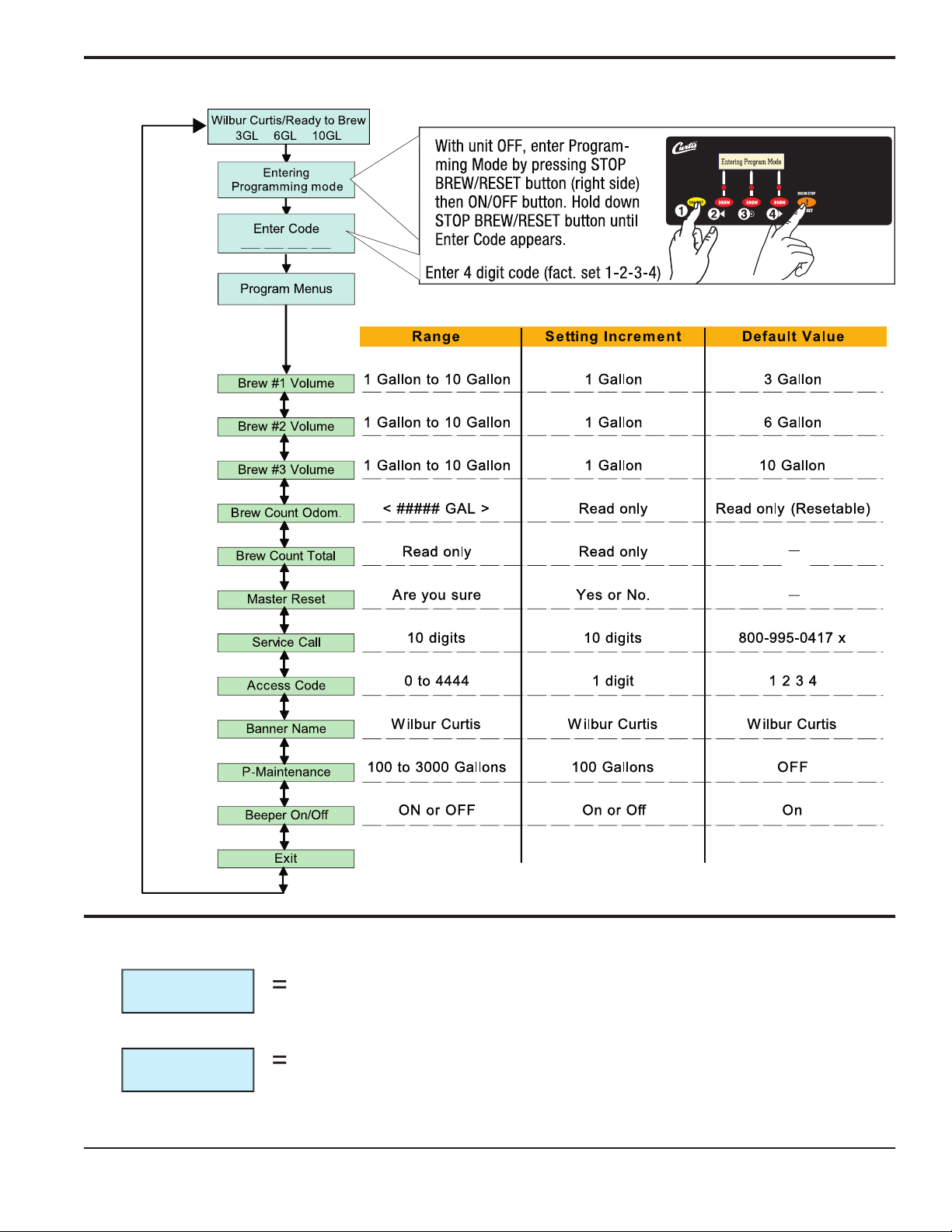
3
PROGRAM MENUS
Entering
Programming mo de
Enter Code
Program Menus
SAFETY STOP
VESSEL ERROR
3 GAL
6GAL
charge arm is improperly inserted over the acorn nut protrusion on top of the lid.
offee
Page 4

ILLUSTRATED PARTS LIST
26
27
28
29
30
31
32
33
34
35
36
37
38
394043
45
46
48
49
50
51
KIT, INLET VALV REPAIR
HOT WATER DELIVERY ARM (MWM-10)
PLUG, MALE #05DL-5M MERCURY
HANDLE, SPRAY ARM BLACK PLASTIC
SWITCH, SAFETY WATER DELIVERY ARM W/CAP
FITTING, COLD WATER TANK PLTD
ELBOW, 1/2 x 3/8 FLRE-FPT PLTD
DEFUSER, WATER MWM
PROBE, WATER LEVEL ASSY MWM-10
FITTING, WATER INLET UPPER TANK
ELEMENT, HEATING 5KW 208V MERCURY
NUT, 1-3/8 - 12 HEX UNS PLATED
HOT WTR LIFT TUBE ASSY MWM-10
FITTING, 3/8 X 5/8 HOSE BARB 90
º
HEATING TANK ONLY MWM
FITTING, ASSY OVERFLOW RESERVOIR TANK
DESCRIPTION
2
3
4
5
6
7
8
9
20
22
23
25
LABEL, CAUTION USE ONLY W/MCV
LABEL, BREWING INSTRUCTIONS ENGLISH
LABEL, 208V POWER BLOCK WIRING DIAG.
LABEL, BREWING INSTRUCTIONS SPANISH
LABEL, POWER ON/OFF
LABEL, CAUTION RESET THERMOSTAT
KIT, UCM & LABEL MWMGT
LABEL, UCM PANEL MERCURY
PLUG, FEMALE #57GB-5F MERCURY
POWER BLOCK, 3 STA 175A 600V
SWITCH, TOGGLE NON-LIT DPST
SOCKET, SAFETY CIRC.RELAY MERC
RELAY, SAFETY CIRCUIT MERCURY
DESCRIPTION
PART N
ITEM
Page 5

ILLUSTRATED
PARTS LIST
4
3
2
7
6
5
9
8
24
232226
27
20
25
31
30
29
28
5
Page 6

ILLUSTRATED
PARTS LIST
34
33
50
32
49
37
38
35
36
43
4039454746
44
48
51
CAUTION:
When clean-
ing, DO NOT use pow-
ders, liquids, cleansers, or
any substance containing chlorine.
These products promote corrosion,
cause pitting of stainless steel and
will void the warranty.
Regular cleaning of the Mercury wall mount brewer, Mercury coffee vessel and cart is essential in maintaining the highest standards of
coffee that your equipment is capable of producing.
cleaned with stainless steel polish only, to prevent scratches.
2. On the vessel, clean the water spreader with a detergent solution and scrub well to remove coffee residue. Rinse with and
clear water. Dry with clean cloth.
3. Remove the wire fi lter holder from the vessel and wash both parts with a detergent solution or put these parts through a
dishwasher.
4. Remove the faucet assembly. Unscrew the handle assembly from the faucet and remove. Clean the faucet shank with a
gage glass brush (circular bristle) by pushing the brush through the shank. Using the same brush clean the faucet body inlet
and outlet. Clean the faucet cap and silicone seat cup.
5. After the cleaning, place the parts (water spreader, basket and faucet parts) into a sink to be sanitized.
To sanitize the disassembled parts:
A. Use a clean container to submerge all parts. Wear rubber gloves for protection.
B. Immerse in commerical Bar Tabs/Sani-Tabs sanitizing solution
The solution must be warm (75°F.) Let the parts soak for at least one minute.
6. Thoroughly rinse parts with hot water. Air dry, all parts that were sanitized.
6
Page 7

ELECTRICAL
7
Page 8

FOR THE LATEST SPECIFICATION INFORMATION GO TO WWW.WILBURCURTIS.COM
8/28/06 . 14.5 . ECN 8488 Rev A
Phone: 800/421-6150
Fax: 323-837-2410
Web Site: www.wilburcurtis.com
3
2
Additionally, the Wilbur Curtis Company warrants its Grinding Burrs for Forty (40) months from date of purchase or 40,000 pounds of coffee,
ment parts are warranted for ninety (90) days from date of purchase or for the remainder of the limited warranty period of the equipment in which
the component is installed.
All in-warranty service calls must have prior authorization. For Authorization, call the Technical Support Department at 1-800-995-0417. Effective
date of this policy is April 1, 2003.
Additional conditions may apply. Go to
to view the full product warranty information.
ment parts installed on Curtis equipment that have not been purchased from the
does not cover and is void under the following circumstances:
2) Improper installation of equipment:
This equipment must be installed by a professional technician and must comply with all local electrical,
mechanical and plumbing codes.
3) Improper voltage:
Equipment must be installed at the voltage stated on the serial plate supplied with this equipment.
4) Improper water supply:
re
sponsibility of the equipment owner. The owner is responsible for proper cleaning and regular maintenance of this equipment.
Equipment damaged in transit is the responsibility of the freight company and a claim should be made with the carrier.
Manufacturer is not responsible for variation in
equipment operation due to excessive lime or local water conditions. The equipment must be maintained according to the manufacturer’s
recommendations.
silicone tube, canister assemblies, whipper chambers and plates, mixing bowls, agitation assemblies and whipper propellers.
9) Repairs and/or Replacements
are subject to our decision that the workmanship or parts were faulty and the defects showed up under normal
use. All labor shall be performed during regular working hours. Overtime charges are the responsibility of the owner. Charges incurred by
delays, waiting time, or operating restrictions that hinder the service technician’s ability to perform service is the responsibility of the owner
of the equipment. This includes institutional and correctional facilities. The Wilbur Curtis Company will allow up to 100 miles, round trip, per
in-warranty service call.
RETURN MERCHANDISE AUTHORIZATION:
All claims under this warranty must be submitted to the Wilbur Curtis Company Technical Sup-
port Department prior to performing any repair work or return of this equipment to the factory. All returned equipment must be repackaged
properly in the original carton. No units will be accepted if they are damaged in transit due to improper packaging.
NO UNITS OR PARTS WILL
BE ACCEPTED WITHOUT A RETURN MERCHANDISE AUTHORIZATION (RMA). RMA NUMBER MUST BE MARKED ON THE CARTON OR
All in-warranty service calls must be performed by an authorized service agent. Call the Wilbur Curtis Technical Support
Department to fi nd an agent near you.
Product Warranty Information
8
 Loading...