

Page 1
F
IND OUT MORE
FIND OUT MORE
THE WEB.
ON
ON
THE WEB.
WILBURCURTIS.COM
WILBURCURTIS.COM
WW
W
WW
ILBURILBUR
ILBUR
ILBURILBUR
C C
C
C C
URTISURTIS
URTIS
URTISURTIS
C C
C
C C
OMPOMP
OMP
OMPOMP
ANYANY
ANY
ANYANY
, I, I
, I
, I, I
NCNC
NC
NCNC
..
.
..
Models Included
SLG
ISLG
CAUTION: CAUTION:
CAUTION: Please
CAUTION: CAUTION:
use this setup
attempting to use this grinder.
Failure to follow the instructions
can result in injury or the voiding
of the warranty.
procedure before
InstallaInstalla
Installa
InstallaInstalla
Important Safeguards/ConventionsImportant Safeguards/Conventions
Important Safeguards/Conventions
Important Safeguards/ConventionsImportant Safeguards/Conventions
This appliance is designed for commercial use. Any servicing other than cleaning and maintenance should be performed by an
authorized Wilbur Curtis service center.
Conventions
QUICK START & SETUP - SLG
1. Install the grinder on a firm, level base in a location where it can be connected to a grounded electrical outlet of 120VAC,
rated at 15 amps.
2. Test the unit by running some whole bean coffee through the grinder. If any problems are encountered, refer to the
troubleshooting section complete at www.wilburcurtis.com or call Technical Service at 800-995-0417.
SETUP INSTRUCTIONS - ISLG
1. Turn both units OFF.
2. Place the grinder close enough to the brewer so the InterLock cable will reach the brewer.
tion Instructions,tion Instructions,
tion Instructions,
tion Instructions,tion Instructions,
• Do NOT immerse the unit in water or any other liquid
• To reduce the risk of fire or electric shock, do NOT open top panel. No user serviceable parts inside. Repair should be done
only by authorized service personnel.
• Keep hands and other items away from hot parts of unit during operation.
• Never clean with scouring powders or harsh implements.
WW
ARNINGS – ARNINGS –
W
ARNINGS –
WW
ARNINGS – ARNINGS –
TT
o help ao help a
void personal injurvoid personal injur
T
o help a
void personal injur
TT
o help ao help a
void personal injurvoid personal injur
OPERATING INSTR UCTIO NS - SLG
The SLG grinder is adjusted at the factory to grind 2 - 2.5 ounces of medium roast coffee.
Ser Ser
Ser
Ser Ser
yy
y
yy
vice & vice &
vice &
vice & vice &
Important Notes/Cautions – from the factorImportant Notes/Cautions – from the factor
Important Notes/Cautions – from the factor
Important Notes/Cautions – from the factorImportant Notes/Cautions – from the factor
WW
arranty Informaarranty Informa
W
arranty Informa
WW
arranty Informaarranty Informa
tiontion
tion
tiontion
yy
y
yy
WARNING TO AVOID
SCALDING, Do not
remove brewcone
while brew light is flashing.
C
ISO 9001 REGISTERED
WILBUR CURTIS COMPANY
Montebello, CA 90640
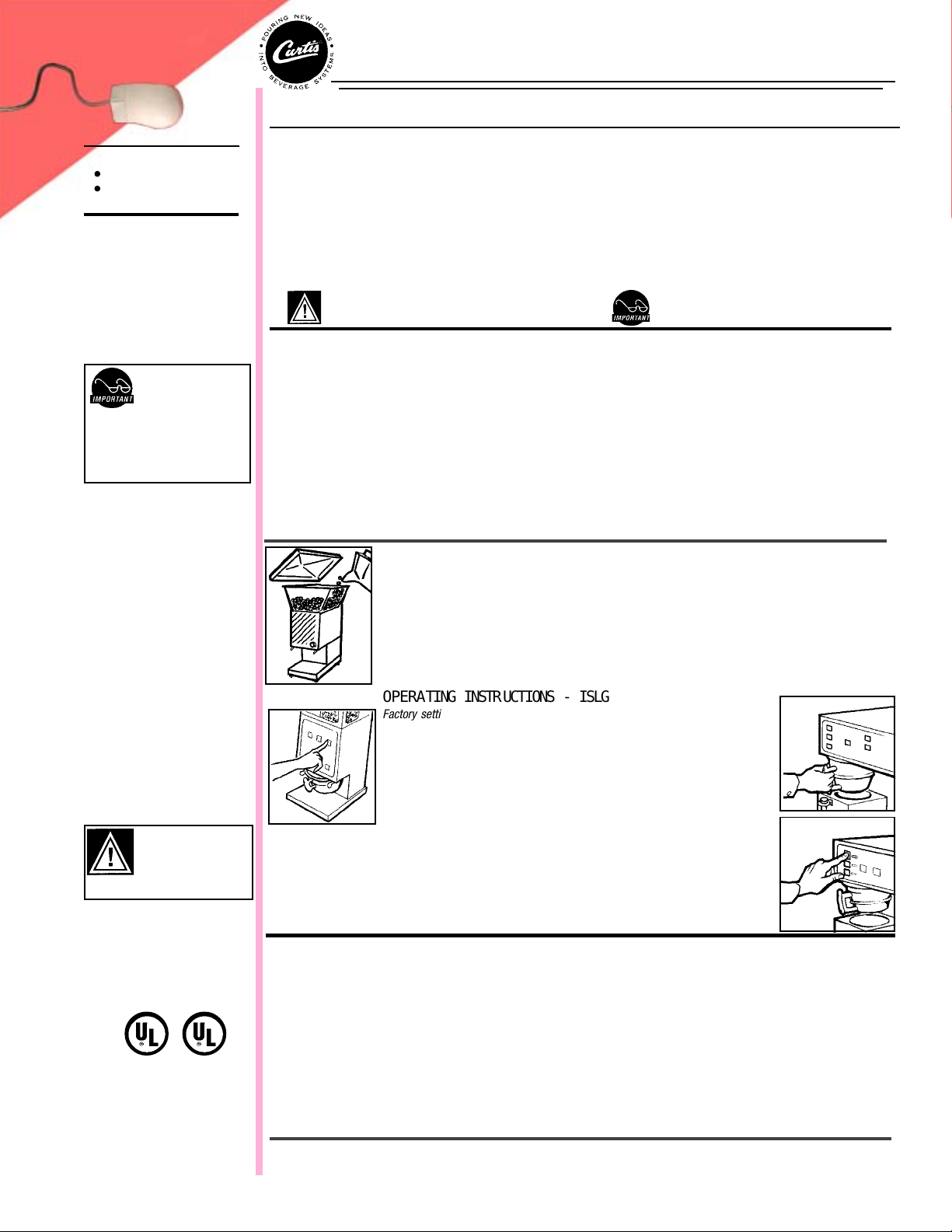
1. Lift off the clear hopper lid and fill the hopper with whole coffee beans.
2. Place a new filter into your brew cone. Slide the brew cone into the brew cone rails on the grinder.
3. Push the START switch on the front panel. The SLG will start to grind coffee into the brew cone.
4. Wait for the grinder motor to stop before removing the brew cone.
OPERATING INSTR UCTIONS - ISLG
Factory settings: SMALL grind button, set for 5 seconds (1.3 oz). LARGE grind
button, set at 15 seconds (3.8 oz). ISLG -13, has additional MEDIUM button set
for 10 seconds.
1. Place the brew cone into the rails on the grinder. Press one of the grind
buttons on the switch panel. Ground coffee will start to fill the brew cone.
2. When the grinder motor stops, remove the brew cone and slide it into the rails
on the brewer.
3. Press the brew switch that displays the blinking indicator light. This starts a brew cycle.
To cancel a brew cycle, press the ON/OFF switch on the brewer. Brew cycles in process will be
cancelled.
ADJUSTING THE GRINDS
Refer to illustration page 2.
1. Empty hopper of coffee beans. Run grinder to clear grinding burrs of coffee.
2. Open housing cover to locate adjustment screw (8) and lock nut (7). Loosen lock nut.
3. Run motor during adjustment. Turning adjustment screw clockwise will result in a finer grind (if, while turning, you hear the
grinding burrs starting to touch, immediately, back off 1/8th turn). Turning counter clockwise will produce a coarser grind.
4. With a screwdriver holding the adjustment screw in place, tighten the locknut.
5. Run some coffee beans through the machine to check the grind adjustment.
6. Replace front cover on machine.
*This adjustment may change the amount of ground coffee dispensed.
FOR THE LATEST SPECIFICATIONS AND INFORMATION GO TO
WWW.WILBURCURTIS.COM
1
Page 2
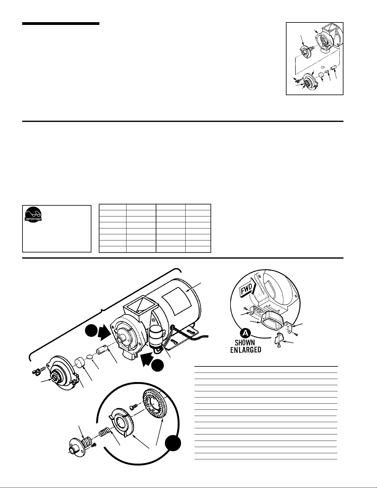
CHANGING A BROKEN SHEAR DISK
1. Unplug power cord.
2. Open hopper and remove beans, then open front cover.
3. On grind motor assembly, take out two thumb screws (10) and remove grind cap (6).
4. Pull out grinding burr/feed worm assembly (2). Inner half of grinding burrs will remain with
housing.
5. Separate shear cap (5) and shear drive (3). Broken shear disk (4) should fall out of slot in
drive.
6. Inspect and clean housing (1) of coffee or debris. Especially, look for something that could
have snapped shear disk.
7. Re-insert feed worm and grinding burr on motor shaft.
8. Push shear drive through burr/feed worm assembly and align large slot with tongue on
motor shaft.
9. Rotate burr/feed worm assembly to align slot with narrow slot on shear drive.
10. Insert a new shear disk into slot. Cover with the shear cap. Replace grind cap and thumb screws.
11. Return power to unit.
1010
10
1010
11
1
11
22
2
22
66
6
66
33
3
33
44
4
44
55
5
88
8
88
77
7
77
55
PROGRAMMING THE ISLG
NOTE:NOTE:
NOTE: Time settings in
NOTE:NOTE:
this table are only
will vary with grind texture and
specific coffee bean. Weigh your
output, then make adjustments as
necessary
ILLUSTRAILLUSTRA
ILLUSTRA
ILLUSTRAILLUSTRA
LISTLIST
LIST
LISTLIST
approximate. Amounts
TED PTED P
TED P
TED PTED P
ARAR
AR
ARAR
TSTS
TS
TSTS
PROGRAMMING THE ISLG
NOTE:NOTE:
NOTE: Before reprogramming the ISLG, the factory timer settings may be all you need.
NOTE:NOTE:
The factory settings: The SMALL grind button is set for 5 seconds (1.3 oz). The LARGE grind button is set at 15 seconds (3.8
oz). On the ISLG -13, there is an additional MEDIUM button that is set for 10 seconds.
1. Open timer cover (behind hopper). Find timer and move the switch from RUN to PROGRAM.
2. Use a stopwatch (recommended) or sweep second hand to time your batches. It is usually quicker to optimize the SMALL
button first. You will then have a more accurate start point for optimizing the other grind button[s].
3. Place an empty filter and cone under the grinder. With your stopwatch ready, press and
button for the desired number of seconds. Weigh the grounds. Record the time and weight. If you are below your target
weight, you can reinsert the filter and add time in small increments by pressing and holding the same button.
Weigh again and add time as desired to reach your target weight. When you are satisfied with the amount, switch the timer
back to RUN and re-grind to test the time and weight. Write down the results.
4. When the time/weight programming is completed, install the front cover.
4
5
6
7
8
10
12
GRINDER MOTORGRINDER MOTOR
GRINDER MOTOR
GRINDER MOTORGRINDER MOTOR
1.0
1.3
1.5
1.8
2.0
2.5
3.0
Seconds OuncesSeconds Ounces
15
20
25
29
34
39
43
10.0
11.3
SETTING TIMER ON SLG GRINDER
3.8
1. Take off timer cover (behind hopper) removing four screws.
5.0
Locate timer.
6.3
2. Timer controls are one high/low switch, allowing you to select a
7.5
scale on timer dial; outside scale range is .5 through 15, inside
8.8
scale range is 2 to 60.
3. Test adjustment by grinding some coffee. When amount is
satisfactory, reinstall timer cover.
hold the
SMALLSMALL
SMALL front panel
SMALLSMALL
2
1
9
12
10
B
11
Item Part No.Item Part No.
Item Part No.
3
4
5
8
6
A
7
15
B
14
2
13
Item Part No.Item Part No.
WC-9135
1
WC-91022
2
WC-91026
3
WC-91024
4
WC-91025
5
WC-91016
6
WC-91017
7
WC-91015
8
WC-91029
9
WC-91027
10
WC-91028
11
WC-91023
12
WC-91045
13
WC-91021
14
WC-91020
15
DescriptionDescription
Description
DescriptionDescription
MOTOR CRUSHING GRINDER ASSY 120VAC
MOTOR, GRINDER 120VAC
CAPACITOR, COFFEE GRINDER ASSY
SHEAR DRIVE COFFEE GRINDER
SHEAR DISK
CAP, SHEAR DISK GRINDERS
COVER, GRINDER HOUSING W/LABEL
SCREW & THRUST PIN ADJUSTING ASSY
SPRINGBAFFLE LONG, NITRIC ACID COLORING
SPRING BAFFLE SHORT, NITRIC ACID COLORING
BAFFLE, SPOUT
SPOUT, GRINDER HOUSING
BURRS, SET CRUSH HIGH FLOW
SPRING, TENSION COFFEE GRINDER
WORM FEEDING ASSY CCG
Page 3

PARTS
DIAGRAMS
SLG Hopper &SLG Hopper &
SLG Hopper &
SLG Hopper &SLG Hopper &
CoversCovers
Covers
CoversCovers
11
1
11
22
2
22
SLG Motor AssemblySLG Motor Assembly
SLG Motor Assembly
SLG Motor AssemblySLG Motor Assembly
77
7
77
33
3
33
44
4
44
1010
10
1010
99
9
88
8
88
99
66
6
66
Item Part No. DescriptionItem Part No. Description
Item Part No. Description
Item Part No. DescriptionItem Part No. Description
WC-9178
1
2
3
4
5
6
7
8
9
10
11
12
13
14
15
15A
WC-9169
WC- 628
WC-1504
WC-3502
WC-6550
WC-9135
WC-38027
WC-3796
WC- 101
WC- 652
WC-6470
WC- 122
WC- 121
WC-39062
WC-39048
HOPPER COVER, CLEAR PLASTIC
HOPPER
TIMER
CIRCUIT BREAKER
FOOT, RUBBER WITH 8-32 STUD
RAILS, BREW CONE
MOTOR, 120V
LABEL, FRONT COVER SLG
LABEL, INSIDE FRONT COVER ADJ GRIND & SHEAR DISK
SWITCH, START
TIMER, INTERLOCK
COVER, FRONT FOR INTERLOCK
SWITCH, 12 CUP, 24 CUP, OR 36 CUP
SWITCH, ON/OFF
LABEL, SWITCH PANEL TWO BATCH (ISLG -10)
LABEL, SWITCH PANEL THREE BATCH (ISLG -13)
Illustrated Parts -Illustrated Parts -
Illustrated Parts -
55
5
55
Illustrated Parts -Illustrated Parts ISLGISLG
ISLG
ISLGISLG
1111
11
1111
1212
12
1212
1313
13
1313
1515
15
1515
1414
14
1414
illustrated Parts Breakdown - ISLG
The parts called out on this illustration are for the ISLG grinder and are the only parts that are different from the SLG
grinder. All other parts are identical. Illustrated, is the ISLG -10 (a two batch grinder). The ISLG -13 uses a slightly
different switch panel and has an additional switch (a three batch grinder).
3
Page 4

ELECTRICAL SCHEMAELECTRICAL SCHEMA
ELECTRICAL SCHEMA
ELECTRICAL SCHEMAELECTRICAL SCHEMA
TICTIC
TIC
TICTIC
WARRANTY We hereby certify that the products manufactured by the Wilbur Curtis Company, Inc., are, to the best of our knowledge, free from all defects and faulty workmanship.
The following warranties and conditions are applicable:
• 90 Days for Labor and 1 Year Parts from Date of Purchase from Factory: This warranty covers all electrical parts, fittings and tubing.
• 40 Months or 40, 000 Pounds of Coffee on a set of Grinding Burrs. (ADS Grinders)
• 2 Years from Date of Purchase: This warranty covers electronic control boards and leaking or pitting of a stainless steel body of a Brewer or Urn.
• 90 Days from Date of Purchase: On replacement parts that have been installed on out of warranty equipment
All in-warranty service calls must have prior authorization from the manufacturer. For an RMA (Return Merchandise Authorization) number, call the Technical Service Department at 1-800-995-0417. The Wilbur Curtis
Company will allow up to 100 miles, round trip, per in-warranty service call.
CONDITIONS & EXCEPTIONS
The warranty covers original equipment at time of purchase only. The Wilbur Curtis Company, Inc., assumes no responsibility for substitute replacement parts installed on Curtis equipment that have not been purchased
from the Wilbur Curtis Company. Inc The Wilbur Curtis Company will not accept any responsibility if the following conditions are not met. The warranty does not cover and is void under these circumstances:
1) Improper operation of equipment. The equipment must be used for its designed and intended purpose and function.
2) Improper installation of equipment. This equipment must be installed by a professional, certified technician and must comply with all local electrical, mechanical and plumbing codes.
3) Wilbur Curtis Company will not be responsible for the operation of equipment at other than the stated voltages on the serial plate.
4) Abuse or neglect (including failure to periodically clean or remove lime accumulations). Manufacturer is not responsible for variation in equipment operation due to excessive lime or local water
conditions.
5) Replacement of items subject to normal use and wear. This shall include, but is not limited to, light bulbs, shear disks, “0” rings, gaskets, canister assemblies. whipper chambers and plates, mixing
bowls, agitation assemblies and whipper propellers.
6) Any faults resulting from inadequate water supply. This includes, but is not limited to, excessive or low water pressure, and inadequate or fluctuating water flow rate.
7) All repairs and/or replacements are subject to our decision that the workmanship or parts were faulty and the defects showed up under normal use.
8) All labor shall be performed during regular working hours. Overtime charges are the responsibility of the owner.
9) Charges incurred by delays, waiting time, or operating restrictions that hinder the service technician’s ability to perform service is the responsibility of the owner of the equipment.
This includes institutional and correctional facilities.
10) All claims under this warranty must be submitted to the Wilbur Curtis Company Technical Service Department before return of the unit to the factory.
11) All equipment returned to us must be repackaged properly in the original carton. No units will be accepted if they are damaged in transit due to improper packaging.
12) Damaged in transit.
13) The resetting of safety thermostats and circuit breakers, programming and temperature adjustments are the responsibility of the equipment owner.
NO UNITS OR PARTS WILL BE ACCEPTED WITHOUT A RETURN MERCHANDISE AUTHORIZATION (RMA). RMA NUMBER MUST BE MARKED ON THE CARTON OR SHIPPING LABEL.
All in-warranty service calls must be performed by an authorized service center, where service is available. Call the factory for location near you.
WILBUR CURTIS CO., INC.
6913 Acco St., Montebello, CA 90640-5403 USA
Phone: 800/421-6150 Fax: 323-837-2410
Technical Service Phone: 800/995-0417 (M-F 5:30A - 4:00P PST) E-Mail: techservice@wilburcurtis.com
Web Site: www.wilburcurtis.com
FOR THE LATEST SPECIFICATION INFORMATION GO TO WWW.WILBURCURTIS.COM
4
Printed in U.S.A. 10/01 F-3217-S Rev NC
10/16/01 . 10.6 . edr 3167 Rev NC
 Loading...