

Page 1
Safety manual
Sicherheitshandbuch
Manuel de sécurité
Manual de seguridad
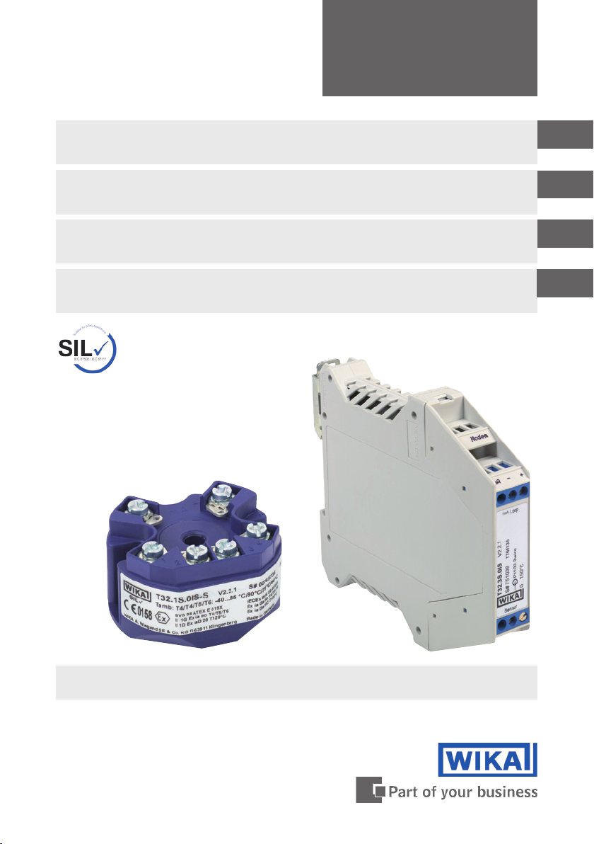
Information on functional safety
for temperature transmitter model T32.xS
Hinweise zur funktionalen Sicherheit
für Temperatur-Transmitter Typ T32.xS
Indications relatives à la sécurité fonctionnelle
pour transmetteur de température type T32.xS
Notas acerca de la seguridad funcional
para transmisores de temperatura modelo T32.xS
Full assessment per IEC 61508
certied by TÜV Rheinland
GB
D
F
E
Head mounting version Rail mounting version
model T32.1S model T32.3S
Page 2

Safety manual model T32.xS
GB
Page 3 - 18
Sicherheitshandbuch Typ T32.xS
D
Manuel de sécurité type T32.xS
F
E
Manual de seguridad modelo T32.xS
Seite 19 - 32
Page 33 - 46
Página 47 - 59
11583631.02 11/2010 GB/D/F/E
2
WIKA safety manual temperature transmitter T32.xS
Page 3
Contents
Contents
1. General information 4
1.1 History of this document 4
1.2 Other applicable instrument documentation 4
1.3 Relevant standards 4
1.4 Abbreviations 5
2. Safety 6
2.1 Intended use in safety applications 6
2.2 Labelling / safety labels 7
2.3 Restrictions to operating modes 8
2.4 Error signaling 9
2.5 Write protection 10
GB
2.6 Accuracy of the safe measuring function 11
2.7 Conguration changes 12
2.8 Commissioning and periodic tests 13
2.8.1 Proof Test of the transmitter's complete signal processing chain 13
2.8.2 Reduced proof test - limited testing of the transmitter's signal
conditioning chain 14
2.9 Information on the determination of safety-relevant parameters 15
2.10 Decommissioning the transmitter 15
Appendix 1: SIL Declaration of Conformity 16
11583631.02 11/2010 GB/D/F/E
WIKA safety manual temperature transmitter T32.xS
3
Page 4
1. General information
1. General information
1.1 History of this document
Documentation changes (compared with the previous issue)
GB
Issue Remarks Firmware
April 2010
May 2010
November
2010
This safety manual on functional safety covers the WIKA temperature transmitter
T32.1S/T32.3S (from Firmware Rev. 2.2.1) solely as part of a safety-related system.
This safety manual is valid with the documentation mentioned in chapter "1.1 Other
applicable instrument documentation". Please also note the safety instructions listed in
the operating manual.
These operating instructions contain important information on working with the Model
T32.1S/T32.3S temperature transmitter. Working safely requires that all safety instructions and work instructions are observed.
First issue
4 languages
(+ French, + Spanish)
Monitoring of the output limits
(optional, not activated by default for
SIL versions starting from 01.01.2011)
T32.1S/ T32.3S
(from Firmware Rev. 2.2.1)
T32.1S/ T32.3S
(from Firmware Rev. 2.2.1)
T32.1S/ T32.3S
(from Firmware Rev. 2.2.1)
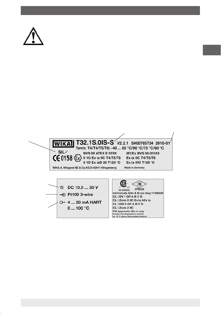
The marking on the product label for the instrument with SIL design is
shown in the following illustration. Only the model T32.xS.0xx-S is suitable
for operation in safety-related applications!
The model T32.xS.0xx-S can be combined with the optional Ex version.
1.2 Other applicable instrument documentation
In addition to this safety manual the operating instructions for model T32.xS
(S-No.: 11258421) and the data sheet TE 32.04 are applicable.
1.3 Relevant standards
Standard Model T32.xS
IEC 61508 Safety-related systems for the process industry
Target groups: Manufacturers and suppliers of instruments
IEC 61511
4
Functional safety safety-related electrical/electronic/ programmable
electronic systems
Target groups: designers, integrators, users
WIKA safety manual temperature transmitter T32.xS
11583631.02 11/2010 GB/D/F/E
Page 5
1. General information
1.4 Abbreviations
Abbreviation
HFT Hardware Fault Tolerance, capability of a functional unit to continue
MTBF Mean interval between two failures
MTTR Mean interval between the occurrence of the failure in a device or
PFD Likelihood of dangerous safety function failures occurring on
PFD
avg
SIL Safety Integrity Level, the international standard IEC 61508
SFF Safe Failure Fraction, the proportion of failures without the potential
T
Proof
XooY Classication and description of the safety-related system with
und λ
λ
sd
λdd +λ
du
λ
du
Description
the execution of the demanded function when faults or anomalies
exist.
system and its repair
demand
Average likelihood of dangerous safety function failures occurring
on demand
denes four discrete safety integrity levels (SIL1 to SIL4). Each
level corresponds to a specic probability range with respect to
the failure of a safety function. The higher the integrity level of the
safety-related system, the lower the likelihood of the demanded
safety functions not occurring.
to put the safety-related system into a dangerous or impermissible
functional state.
In accordance with IEC 61508-4, chapter 3.5.8, TProof is dened
as the periodic testing to expose errors in a safety-related system.
respect to redundancy and the selection procedure used. "Y"
indicates how often the safety function is carried out (redundancy).
"X" determines how many channels must work properly.
λsd Safe detected + λsu Safe undetected
su
Safe failure (IEC 61508-4, chapter 3.6.8):
A safe failure is present when the measuring system switches to the
dened safe state or the fault signalling mode without the process
demanding it.
λdd Dangerous detected + λdu Dangerous undetected
Unsafe failure (IEC 61508-4, chapter 3.6.7):
Generally a dangerous failure occurs if the measuring system
switches into a dangerous or functionally inoperable condition.
λdu Dangerous undetected
A dangerous undetected failure occurs if the measuring system does
not switch into a safe condition or into the error mode on a demand
from the process.
GB
For further relevant abbreviations, see IEC 61508-4.
11583631.02 11/2010 GB/D/F/E
WIKA safety manual temperature transmitter T32.xS
5
Page 6
2. Safety
2. Safety
2.1 Intended use in safety applications
All safety functions relate exclusively to the analogue output signal (4 … 20 mA). The
GB
device is certied to SIL2 (IEC 61508) . The device software fullls the criteria for SIL3
(IEC 61508). The use of the device in homogeneous reduntant systems is therefore
possible.
The following sensor connections achieve an SFF (Safe Failure Fraction) of >90 %,
sucient for SIL2:
■
Thermocouple (internal cold junction, Pt100)
■
Thermocouple (external cold junction, Pt100)
■
Resistance thermometer with 4-wire connection
■
Resistance thermometer with 3-wire connection
WIKA sensors Model TRxx (see WIKA manufacturer's declaration
Document No. 3011701)
■
Duplex thermocouple and/or duplex resistance thermometer (only in "redundant"
operating mode and when both sensors are used for monitoring the same
measurement point (2 channel)).
The following sensor connections achieve an SFF (Safe Failure Fraction) of >60 % for
SIL1:
■
Resistance thermometers with 3-wire connection
- universal sensors -
■
Resistance thermometers with 2-wire connection
The device generates a current signal in the approved measuring mode of a nominal
4 … 20 mA, that is dependent upon the sensor signal. The eective range of the output
signal limited to a minimum of 3.8 mA and a maximum of 20.5 mA (factory setting in
basic conguration).
WARNING!
Do not exceed the specications for the model T32.xS given in the data
sheets and operating instructions. In order to ensure a safe functionality
of the current output, the correct terminal voltage must be present in the
device.
The following terminal voltage limits apply:
Instrument model Terminal voltage limits
T32.1S.000-S
T32.3S.000-S
T32.1S.0IS-S
T32.3S.0IS-S
6
DC 10,5 ... 42 V
DC 10,5 ... 30 V
WIKA safety manual temperature transmitter T32.xS
11583631.02 11/2010 GB/D/F/E
Page 7
2. Safety
WARNING !
The following sensors and oerating modes are NOT allowed for operation
in a safety-relevant application:
■
Potentiometer
■
Resistance sensor
■
mV-Sensor
■
Dierential mode in duplex sensor operation
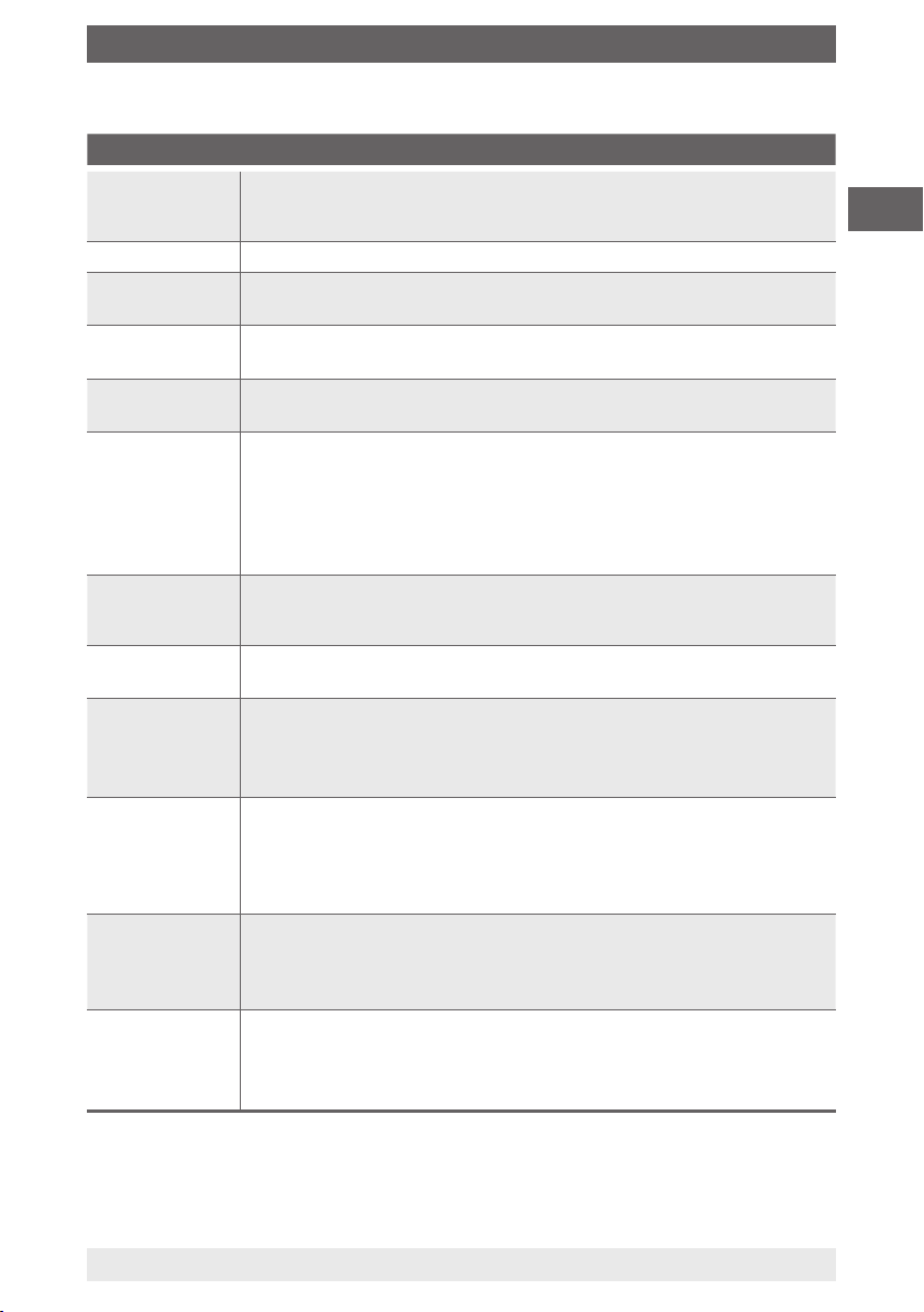
2.2 Labelling / safety labels
Product label
■
Head mounting version, model T32.1S
GB
SIL version
(only at SIL)
Power supply
Sensor, Pt100
or RTD
Output signal
Model
with SIL: T32.1S.0IS-S
without SIL: T32.1S.0IS-Z
Date of manufacture
(year-month)
11583631.02 11/2010 GB/D/F/E
WIKA safety manual temperature transmitter T32.xS
7
Page 8
GB
2. Safety
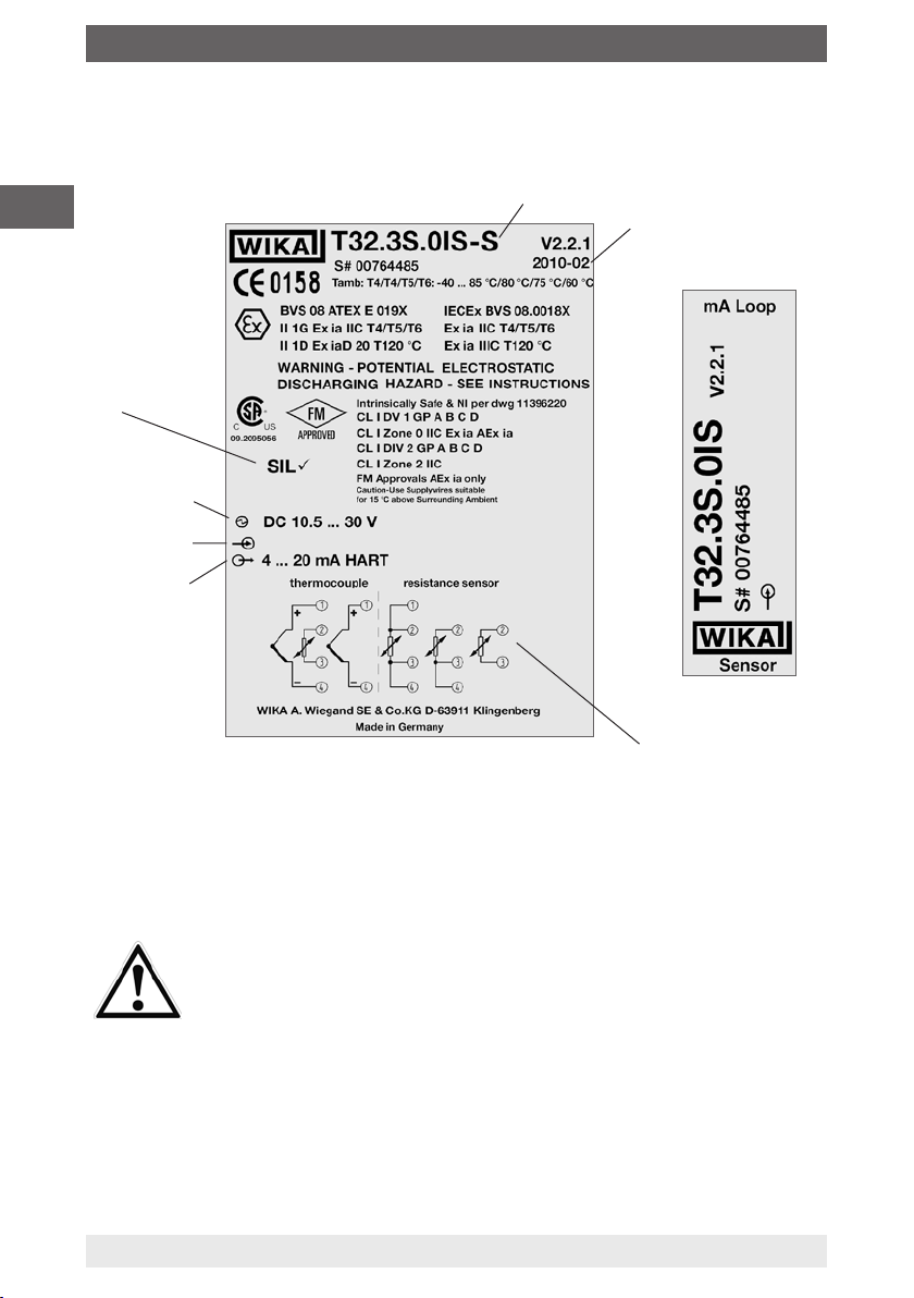
■
Rail mounting version, model T32.3S
SIL version
(only at SIL)
Power supply
Sensor, Pt100
or RTD
Output signal
Model
with SIL: T32.1S.0IS-S
without SIL: T32.1S.0IS-Z
Date of manufacture
(year-month)
2.3 Restrictions to operating modes
WARNING!
Under the following operating conditions, the safety function of the device
is not guaranteed:
■
During conguration
■
When the write-protection is deactivated
■
When the HART® multi drop mode is activated.
■
Measured value transmission via HART® protocol
■
During a simulation
■
During the Proof Tests
■
When the write-protection is deactivated
8
Pin assignment
11583631.02 11/2010 GB/D/F/E
WIKA safety manual temperature transmitter T32.xS
Page 9

2. Safety
2.4 Error signaling
The model T32.xS temperature transmitter monitors the connected sensors and its
own hardware for errors. In the event of a known error condition the device generates
an error signalling current.
The response time from the sensor is a maximum of 90 seconds.
This implies the discovery of the following potential errors:
■
Sensor burnout
■
Sensor short circuit (only for resistance temperature sensors, not for thermocouples)
■
Inadmissably high lead resistance (not with duplex resistance temperature sensors)
The online diagnosis-test interval of the instrument should be a maximum of
35 minutes. This implies the discovery of the following potential device errors:
■
ROM error
■
EEPROM error
■
RAM error
■
Program-counter error
■
Stack-pointer error
Furthermore, the following monitoring functions are carried out continuously:
■
Logical program ow control
■
Internal communications error
■
Over sensor upper limit
■
Under sensor lower limit
■
Cold junction temperature outside permissible limits (only for thermocouples)
■
Duplex sensor drift monitoring (activated optionally)
■
Conguration error
■
Monitoring of the permissible device temperature (optional, activated by default for
SIL versions)
■
Monitoring of the output limits (optional, not activated by default for SIL versions
starting from 01.01.2011)
GB
CAUTION!
The device's error signalling current (error current) is congured in
accordance with the following requirements:
■
Error current fail high (high alarm value):
settable in the range ≥ 21.0 mA to ≤ 23.0 mA (upscale)
■
Error current fail low (low alarm value) :
settable in the range ≥ 3.5 mA to ≤ 3.6 mA (downscale)
11583631.02 11/2010 GB/D/F/E
WIKA safety manual temperature transmitter T32.xS
9
Page 10
2. Safety
WARNING!
With certain device-side diagnosed hardware errors, the device gives a
downscale error signal with a loop current of < 3.8 mA, and can however,
GB
With certain inadmissible congurations (e.g. with deactivated write-protection) the
transmitter likewise generates an error signal. In order to nd the reason behind the
error signal, the diagnostic functions available over HART
functions are oered, for example, in the WIKA_T32 conguration software (free
download from www.wika.com).
2.5 Write protection
The T32.xS oers a write protection functionality in order to prevent accidental
conguration changes. The write-protection password is factory set to "0".
for technical reasons, also ensure no signal ≤ 3.6 mA with the appropriate
conguration. The evaluation system must therefore interpret a loop
current of < 3.8 mA as a fault condition.
®
should be used. Such
A T32.xS temperature transmitter with SIL option will only work once the
write protection has been activated. Without write protection activated,
such a transmitter will signal an error.
2.5.1 Operation of the write protection
The write protection function is activated via a passsword (numbers in the range 0 to
65535 are allowed) and through a switch (write protection activate/deactivate).
A change in the state of the write protection switch is only possible after the successful
input of the password. The password can be altered via its own menu.
CAUTION!
There is absolutely NO possibility of retrieving a forgotten password! The
only possibility is for the password to be reset at the factory!
Also, activation of the write protection is only possible through the input of
the correct password!
10
WIKA safety manual temperature transmitter T32.xS
11583631.02 11/2010 GB/D/F/E
Page 11
2. Safety
2.6 Accuracy of the safe measuring function
The following information on the Total Safety Accuracy contains the following components:
■
Basic accuracy (measuring deviation from input and output, and the linearity error
of the transmitter)
■
In addition, for thermocouples, the internal cold-junction compensation (CJC),
except for type B thermocouples
■
Inuence of the ambient temperature in the range -50 ... +85 °C
The dened value for the Total Safety Accuracy for this instrument depends on the
chosen sensor type, and the congured measuring span (see following table).
Up to the minimum spans given in the table, the Total Safety Accuracy is 2 % of the
measuring range with respect to the current output signal of 16 mA.
Otherwise, the absolute values given directly in the table are valid.
CAUTION!
The measuring span is the dierence between the full scale value and the
initial value of a measuring range.
GB
Sensor
type
Permissible
sensor range
for the accuracy
Min. span for
2 % total safety
accuracy
specications
Pt100 -200 ... +850 °C 84 K
JPt100 -200 ... +500 °C 50 K
Ni100 -60 ... +250 °C 21 K
Pt1000
Pt500 70 K 2 K
Pt25 134 K 3 K
Pt10 241 K 5 K
TC type T -150 ... +400 °C 134 K
TC typeL -150 ... +900 °C 138 K
TC type U -150 ... +600 °C 136 K
TC type E -150 ... +1000 °C 164 K
TC type J -150 ... +1200 °C 176 K
TC type K -140 ... +1200 °C 197 K
TC type N -150 ... +1300 °C 154 K
TC type R +50 … +1600 °C 255 K
TC type S +50 … +1600 °C 273 K
TC type B +500 …+1820 °C 283 K
11583631.02 11/2010 GB/D/F/E
WIKA safety manual temperature transmitter T32.xS
-200 ... +850 °C
69 K 2 K
Absolute total
safety accuracy for
small measuring
spans
2 K
3 K
4 K
6 K
11
Page 12
2. Safety
Application (see table page 11):
■
Example 1
Sensor type Pt100, congured measuring range = -50 … +100 °C, so congured
GB
measuring span = 150 K.
This is not smaller than 84 K. Thus the Total Safety Accuracy is 2 % FS,
thus 2 % * 150 K = 3 K,
and/or 2 % * 16 mA = 320 μA in terms of the current output
■
Example 2
Sensor type Pt100, congured measuring range = 0 … 50 °C, so congured
measuring span = 50 K
This is smaller than 84 K, thus the total safety accuracy is 2 K,
thus 2 K / 50 K = 4 %, and 4 % * 16 mA = 640 μA in terms of the current output
2.7 Conguration changes
WARNING!
During the conguration change, the safety function is not active! Safe
operation is only admissible with activated write protection (password).
Carry out conguration changes within the permissible specications in accordance
with chapter "2.1 Intended use in safety applications".
With the supplied conguration tools, the write protection, and other items, for the
model T32.xS is settable:
■
WIKA T32 Conguration Software
■
AMS
■
SIMATIC PDM
■
DTM (from Version DTM Beta version V1.0.2, January 2003) in conjunction with
operating software to the FDT/DTM Standard, e.g. PACTware, FieldMate
■
HART® hand-held terminal FC475, FC375, MFC4150
WARNING!
The safety function must be checked following any conguration
procedure.
12
WIKA safety manual temperature transmitter T32.xS
11583631.02 11/2010 GB/D/F/E
Page 13

2. Safety
2.8 Commissioning and periodic tests
The operability and error current of the model T32.xS temperature transmitter must
be tested both during commissioning and at reasonable intervals. Both the nature of
the tests as well as the chosen intervals are the responsibility of the user. The interval
usually conforms to the PFDavg value given in the standard (Values and key data see
"Appendix 1: SIL declaration of conformity"). Normally the repeated test happens every
year.
2.8.1 Proof test of the transmitter's complete signal processing chain
1. If required, bypass the safety controller system and/or take the appropriate action,
to prevent an alarm being triggered unintentionally.
2. Deactivate the device's write protection
3. With the aid of the HART
high alarm value (≥ 21.0 mA). (HART
4. Test whether the current output signal reaches this value.
5. With the aid of the function in simulation mode, set the current output of the
transmitter to a low alarm value (≤ 3.6 mA)
6. Test whether the current output signal reaches this value.
7. Activate the write protection and wait for a minimum of 5 seconds.
8. Switch the device o, or disconnect from the power supply.
9. Restart the device and wait at least 15 seconds from the switch-on time.
10. Check the current output with reference temperature 1) at 2 points. Select for the
initial value, (4 mA to +20 % of the span) and for the nal value (20 mA up to –20 %
of the span).
11. When using a customer-specic linearisation, this must be checked at a minimum
of three points.
12. Remove the bypass on the safety controller system or return to a normal operating
condition for other measures.
13. Following the tests, the results must be documented and archived accordingly.
®
function in simulation mode, set the current output to a
®
command 40: Enter Fixed Current-Mode)
GB
1) checking transmitters without sensors can also be achieved with an appropriate sensor
simulator (Simulator, ref. voltage source, etc.). Here the sensor must be tested to the SIL
demands of the customer's application. The measuring or setting accuracy of the test
instruments used should be at least 0.2 % of the span of the current output (16 mA).
With the testing described above a diagnostic cover of 99% will be
achieved.
11583631.02 11/2010 GB/D/F/E
WIKA safety manual temperature transmitter T32.xS
13
Page 14
2. Safety
2.8.2 Reduced proof test - limited testing of the transmitter's signal
conditioning chain
1. Bypass the safety controller system and/or take the appropriate action, to prevent
GB
an alarm being triggered unintentionally.
2. Deactivate the device's write protection
3. With the aid of the HART
®
function in simulation mode, set the current output to a
high alarm value (≥ 21.0 mA).
4. Test whether the current output signal reaches this value.
5. With the aid of the function in simulation mode, set the current output of the
transmitter to a low alarm value (≤ 3.6 mA)
6. Test whether the current output signal reaches this value.
7. Activate the write protection and wait for a minimum of 5 seconds.
8. Switch the device o, or disconnect from the power supply.
9. Restart the device and wait at least 15 seconds from the switch-on time.
10. Read the device status
11. Evaluate the device status and check it for conformity with the specications in the
operating instructions.
12. Read the device diagnostics
13. Evaluate the device diagnostics and check it for conformity with the specications
in the operating instructions.
14. Remove the bypass on the safety controller system or return to a normal operating
condition for other measures.
15. Following the tests, the results must be documented and archived accordingly
In contrast to the procedures described in 2.8.1., the signal conditioning chain is not tested here.
Its operational reliability should be ensured through reading and evaluating the device status and
device diagnostics.
With the testing described above, a diagnostic cover of 73 % will be
achieved.
WARNING!
Following the checking of the safety function, the device should be
secured against interference through write protection, since any change
in parameter can prejudice the safety function. The write protection should
be checked as follows: send a write instruction to the model T32.xS via a
®
HART
command. The temperature transmitter must acknowledge this
instruction with the message "Instrument is write protected".
WARNING!
The methods and procedures used for these tests (test scenarios) must
also be documented like the test results
. If the outcome of the function test
is negative, the whole system must be shut down. The process must be
put into a safe condition using appropriate procedures.
14
WIKA safety manual temperature transmitter T32.xS
11583631.02 11/2010 GB/D/F/E
Page 15
2. Safety
WARNING!
After the proof test of the device, start a functional check of the entire
safety function (safety loop) in order to test whether the transmitter
ensures the safety function of the system. Function tests are intended
to demonstrate the correct function of the whole safety-related system,
including all instruments (sensor, logic unit, and actuator).
2.9 Information on the determination of safety-relevant parameters
The failure rates of the electronics were determined using FMEDA in accordance
with IEC 61508. The calculations were based upon the component failure rates in
accordance with SN 29500.
The following assumptions have been made:
■
The transmitter are only operated in low demand mode applications.
■
The mean ambient temperature during the period of operation is 40 °C.
■
The MTTF following a device failure is 8 hours.
In accordance with ISO 13849-1 a maximum service life for the transmitter of 20 years
is assumed. Replace the device after this time.
2.10 Decommissioning the transmitter
GB
WARNING!
Ensure dvices that have been taken out of service are not accidentally
recommissioned (e.g. through marking the instrument). After
decommissioning the temperature transmitter, a functional test of the
entire safety function (safety loop) should be initiated, in order to test
whether the safety function of the system is still ensured. Function tests
are intended to demonstrate the correct function of the whole safetyrelated system, including all instruments (sensor, logic unit, and actuator).
11583631.02 11/2010 GB/D/F/E
WIKA safety manual temperature transmitter T32.xS
15
Page 16
Appendix 1: SIL Declaration of Conformity
GB
SIL Declaration of Conformity
Functional safety per DIN EN 61508 / DIN EN 61511
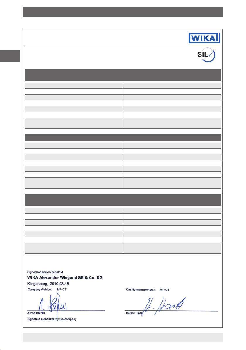
WIKA Alexander Wiegand SE & Co. KG, Alexander Wiegand Straße 30, 63911 Klingenberg
declares as the manufacturer the accuracy of the following information.
1. General information
Permissible options
Safety-relevant output signal 4 … 20 mA
Error current Adjustable: ≤ 3.6 mA and ≥ 21.0 mA
Evaluated measurands /function Temperature in °C, °F, K, R
Safety function Single sensor
Device type per IEC 61508-2 B (complex components)
Operating mode Low Demand Mode
Current hardware version 6
Current software version (Firmware) 2.2.1
Safety handbook Issue 05/2010
Type of evaluation Complete evaluation, in parallel with development,
Evaluation through Report No. TÜV Rheinland 968/EL 632.01/10
Test documents Safety-Product Requirement Specication
T32.1S.xxx-S / T32.3S.xxx-S (xxx = 000/0IS/0NI)
(Factory settings: 3.5 mA and 21.5 mA to NAMUR
NE43)
Duplex sensor, Redundant, Minimum value,
Maximum value, Average value
of hardware and software incl. FMEDA on a
component level and change process to
IEC 61508-2,3
Product Requirements Specication
Functional Safety Management Plan
Product verication plan
Data Sheet TE 32.04
FMEA at component level
Safety handbook
2. SIL Integrity
Systematic safety integrity SIL3-capable software
Integrity against "random, dangerous
hardware errors"
(Type B components)
16
Single channel operation (HFT = 0, e.g. 1v1); SIL2
Two channel operation SIL3: to IEC 61508-6 Annex D
must determine a β-factor for the two channel (redundant) application, in order to incorporate the 'Common
Cause Failure Probability'.
For further information, see WIKA contact data
WIKA safety manual temperature transmitter T32.xS
Page 1/3
11583631.02 11/2010 GB/D/F/E
Page 17
Appendix 1: SIL Declaration of Conformity
SIL Declaration of Conformity
Functional safety per DIN EN 61508 / DIN EN 61511
3.1 FMEDA Pt100 3-wire (safety function for 4 … 20 mA output)
λ
du
λ
dd
λsu +λ
sd
SFF – Safe Failure Fraction 98.6 %
MTTR 8 h
PFD for T
1 year 1.316 x 10
proof
DC proof-test-coverage
incl. signal conditioning chain
3.2 FMEDA Pt100 4-wire (safety function for 4 … 20 mA output)
λ
du
λ
dd
λsu +λ
sd
SFF – Safe Failure Fraction 98.6 %
MTTR 8 h
PFD for T
1 year 1.482 x 10
proof
DC proof-test-coverage
incl. signal conditioning chain
3.3 FMEDA Pt100 2-wire (safety function for 4 … 20 mA output)
λ
du
λ
dd
λsu +λ
sd
SFF – Safe Failure Fraction 81.2 %
MTTR 8 h
PFD for T
DC proof-test-coverage
incl. signal conditioning chain
1 year 1.815 x 10
proof
30 FIT
2037 FIT
118 FIT
99 %
34 FIT
2037 FIT
119 FIT
99 %
414 FIT
1657 FIT
118 FIT
99 %
1)
1)
1)
-4
1)
1)
1)
-4
1)
1)
1)
-3
GB
2)
3.4 FMEDA thermocouple with internal cold junction
(safety function for 4 … 20 mA output)
λ
du
λ
dd
λsu +λ
sd
SFF – Safe Failure Fraction 94.9 %
MTTR 8 h
PFD for T
1 year 1.162 x 10
proof
DC proof-test-coverage
incl. signal conditioning chain
1) FIT = Failure in time, Unit: Quantity of failures per 10
2) Determine the distribution of error patterns in WIKA TRxx Sensors
11583631.02 11/2010 GB/D/F/E
265 FIT
4807 FIT
116 FIT
99 %
9
h
WIKA safety manual temperature transmitter T32.xS
1)
1)
1)
-3
Page 2/3
17
Page 18
Appendix 1: SIL Declaration of Conformity
GB
SIL Declaration of Conformity
Functional safety per DIN EN 61508 / DIN EN 61511
3.5 FMEDA thermocouple with external cold junction
(safety function for 4 … 20 mA output)
λ
du
λ
dd
λsu +λ
sd
SFF – Safe Failure Fraction 90.7 %
MTTR 8 h
PFD for T
1 year 2.91 * 10
proof
DC proof-test-coverage
incl. signal conditioning chain
3.6 FMEDA duplex sensor Pt100 (safety function for 4 … 20 mA output)
λ
du
λ
dd
λsu +λ
sd
SFF – Safe Failure Fraction 98.8 %
MTTR 8 h
PFD for T
1 year 2.495 * 10
proof
DC proof-test-coverage
incl. signal conditioning chain
3.7 FMEDA duplex sensor thermocouple with internal cold junction
(safety function for
λ
du
λ
dd
λsu +λ
sd
SFF – Safe Failure Fraction 95.3 %
MTTR 8 h
PFD for T
DC proof-test-coverage
incl. signal conditioning chain
1) FIT = Failure in time, Unit: Quantity of failures per 10
proof
4 … 20 mA output
)
1 year 2.262 * 10
664 FIT
6407 FIT
118 FIT
99 %
57 FIT
4017 FIT
119 FIT
99 %
516 FIT
9557 FIT
117 FIT
99 %
9
h
1)
1)
1)
-3
1)
1)
1)
-4
1)
1)
1)
-3
18
Page 3/3
WIKA safety manual temperature transmitter T32.xS
11583631.02 11/2010 GB/D/F/E
Page 19

Inhalt
Inhalt
1. Allgemeines 20
1.1 Historie dieses Dokumentes 20
1.2 Mitgeltende Gerätedokumentationen 20
1.3 Relevante Normen 20
1.4 Abkürzungen 21
2. Sicherheit 22
2.1 Bestimmungsgemäße Verwendung in Sicherheitsanwendungen 22
2.2 Beschilderung / Sicherheitskennzeichnungen 23
2.3 Einschränkung der Betriebsarten 24
2.4 Fehlersignalisierung 25
2.5 Schreibschutz 26
2.6 Genauigkeit der sicheren Messfunktion 27
2.7 Kongurationsänderungen 28
2.8 Inbetriebnahme und wiederkehrende Prüfungen 29
2.8.1 Proof Test der kompletten Signalverarbeitungskette des Transmitters 29
2.8.2 Reduzierter Prooftest - eingeschränkte Prüfung der Signalverarbeitungskette des Transmitters 30
2.9 Hinweise zur Ermittlung sicherheitstechnischer Kenngrößen 31
D
2.10 Außerbetriebnahme des Transmitters 31
Anlage 1: SIL Konformitätserklärung 16
11583631.02 11/2010 GB/D/F/E
WIKA Sicherheitshandbuch Temperatur-Transmitter T32.xS
19
Page 20

1. Allgemeines
1. Allgemeines
1.1 Historie dieses Dokumentes
Dokumentationsänderungen (verglichen mit der vorherigen Ausgabe)
Ausgabe Bemerkung Firmware
April 2010 Erstausgabe T32.1S/ T32.3S
D
Mai 2010 4 Sprachen
(+ Französisch, + Spanisch)
November
2010
Dieses Sicherheitshandbuch zur funktionalen Sicherheit behandelt die WIKA Temperatur-Transmitter Typ T32.1S/T32.3S (ab Firmware Rev. 2.2.1) lediglich als Teil einer
Sicherheitsfunktion. Dieses Sicherheitshandbuch gilt im Zusammenhang mit den unter
„1.2 Mitgeltende Gerätedokumentationen“ genannten Dokumentationen. Zusätzlich
die Sicherheitshinweise in der Betriebsanleitung beachten.
Die Betriebsanleitung enthält wichtige Hinweise zum Umgang mit dem TemperaturTransmitter Typ T32.1S/T32.3S. Voraussetzung für sicheres Arbeiten ist die Einhaltung
aller angegebenen Sicherheitshinweise und Handlungsanweisungen.
Überwachung der Ausgangsgrenzen
(optional, bei SIL Ausführung ab
01.01.2011 als default nicht aktiviert)
(ab Firmware Rev. 2.2.1)
T32.1S/ T32.3S
(ab Firmware Rev. 2.2.1)
T32.1S/ T32.3S
(ab Firmware Rev. 2.2.1)
Die Kennzeichnung der Geräte mit SIL-Ausführung auf den
Typenschildern ist in den folgenden Darstellungen erläutert. Nur der Typ
T32.xS.0xx-S ist für den Einsatz in sicherheitsgerichteten Anwendungen
geeignet!
Der Typ T32.xS.0xx-S ist beliebig mit den verfügbaren Ex-Ausführungen
kombinierbar.
1.2 Mitgeltende Gerätedokumentationen
Ergänzend zu diesem Sicherheitshandbuch gelten die Betriebsanleitung für
Typ T32.xS (S-Nr.: 11258421) sowie das Datenblatt TE 32.04.
1.3 Relevante Normen
Norm Typ T32.xS
IEC 61508 Sicherheitstechnische Systeme für die Prozessindustrie
Zielgruppe: Hersteller und Lieferanten von Geräten
IEC 61511
20
Funktionale Sicherheit sicherheitsbezogener elektrischer/elektronischer/
programmierbarer elektronischer Systeme
Zielgruppe: Planer, Errichter Nutzer
WIKA Sicherheitshandbuch Temperatur-Transmitter T32.xS
11583631.02 11/2010 GB/D/F/E
Page 21

1. Allgemeines
1.4 Abkürzungen
Abkürzung
HFT Hardware Fehlertoleranz; Fähigkeit einer Funktionseinheit, eine
MTBF Mittlere Zeitdauer zwischen zwei Ausfällen
MTTR Mittlere Zeitdauer zwischen dem Auftreten eines Fehlers in einem
PFD Wahrscheinlichkeit gefahrbringender Ausfälle einer Sicherheits-
PFD
avg
SIL Safety Integrity Level; Die internationale Norm IEC 61508 deniert
SFF Anteil ungefährlicher Ausfälle, Anteil von Ausfällen ohne Poten-
T
Proof
XooY Klassizierung und Beschreibung des sicherheitsbezogenen
und λ
λ
sd
λdd +λ
du
λ
du
Beschreibung
geforderte Funktion bei Bestehen von Fehlern oder Abweichungen
weiter auszuführen.
Gerät oder System und der Reparatur
funktion im Anforderungsfall
Mittlere Wahrscheinlichkeit gefahrbringender Ausfälle einer Sicher-
heitsfunktion im Anforderungsfall
vier diskrete Safety Integrity Level (SIL1 bis SIL4). Jeder Level
entspricht einem Wahrscheinlichkeitsbereich für das Versagen einer
Sicherheitsfunktion. Je höher der Safety Integrity Level der sicherheitsbezogenen Systeme ist, umso geringer ist die Wahrscheinlichkeit, dass sie die geforderten Sicherheitsfunktionen nicht ausführen.
tial, das sicherheitsbezogene System in einen gefährlichen oder
unzulässigen Funktionszustand zu versetzen.
Nach IEC 61508-4, Abschnitt 3.5.8 wird TProof deniert als wiederkehrende Prüfung zur Aufdeckung von Ausfällen in einem sicherheitsbezogenen System.
Systems hinsichtlich Redundanz und angewandtem Auswahlverfahren. "Y" gibt an, wie oft die Sicherheitsfunktion ausgeführt
wird (Redundanz). "X" bestimmt, wie viele Kanäle korrekt arbeiten
müssen.
λsd Safe detected + λsu Safe undetected
su
Ungefährlicher Ausfall (IEC 61508-4, Abschnitt 3.6.8):
Ein ungefährlicher Ausfall (safe failure) liegt vor, wenn das Messsystem ohne Anforderung des Prozesses in den denierten sicheren
Zustand oder in den Fehler-Signalisierungsmodus wechselt.
λdd Dangerous detected + λdu Dangerous undetected
Gefährlicher Ausfall (IEC 61508-4, Abschnitt 3.6.7):
Generell liegt ein gefährlicher Ausfall dann vor, wenn das Messystem
in einen gefährlichen oder funktionsunfähigen Zustand versetzt wird.
λdu Dangerous undetected
Ein gefährlicher unentdeckter Ausfall liegt vor, wenn das Messsystem
bei einer Anforderung des Prozesses weder in den denierten
sicheren Zustand, noch in den Fehler-Signalisierungsmodus wechselt.
D
Weitere relevante Abkürzungen siehe IEC 61508-4.
11583631.02 11/2010 GB/D/F/E
WIKA Sicherheitshandbuch Temperatur-Transmitter T32.xS
21
Page 22

2. Sicherheit
2. Sicherheit
2.1 Bestimmungsgemäße Verwendung in Sicherheitsanwendungen
Sämtliche Sicherheitsfunktionen beziehen sich ausschließlich auf das analoge
Ausgangsignal (4 … 20 mA). Das Gerät ist nach SIL2 (IEC 61508) zertiziert. Die
Software des Gerätes erfüllt die Kriterien für SIL3 (IEC 61508). Der Einsatz des
Gerätes in homogen redundanten Systemen ist damit möglich.
D
Folgende Sensoranschlüsse erreichen eine für SIL2 ausreichende SFF (Safe Failure
Fraction) von >90 %:
■
Thermoelement (Vergleichsstelle intern, Pt100)
■
Thermoelement (Vergleichsstelle extern, Pt100)
■
Widerstandsthermometer mit 4-Leiter Anschluss
■
Widerstandsthermometer mit 3-Leiter Anschluss
WIKA-Sensoren Typ TRxx (siehe WIKA-Herstellererklärung Dokument Nr. 3011701)
■
Doppel-Thermoelement bzw. Doppel-Widerstandsthermometer
(Nur in der Betriebsart „redundant“ und wenn beide Sensoren für die Überwachung
der gleichen Messstelle verwendet werden (2-kanalig)).
Folgende Sensoranschlüsse erreichen eine für SIL1 ausreichende SFF (Safe Failure
Fraction) von >60 %:
■
Widerstandsthermometer mit 3-Leiter Anschluss
- Universelle Sensoren -
■
Widerstandsthermometer mit 2-Leiter Anschluss
Das Gerät erzeugt ein vom Sensorsignal abhängiges Stromsignal im zulässigen
Messbetrieb von nominal 4 … 20 mA. Der gültige Bereich des Ausgangssignals ist auf
ein Minimum von 3,8 mA und ein Maximum von 20,5 mA begrenzt (Werkseinstellung
bei Grundkonguration).
WARNUNG!
Die im Datenblatt bzw. in der Betriebsanleitung angegebenen Spezikationen des Typs T32.xS nicht überschreiten. Um eine sichere Funktion
des Stromausgangs zu gewährleisten, muss insbesondere die korrekte
Klemmenspannung am Gerät anliegen.
Folgende Klemmenspannungsgrenzen einhalten:
Geräte-Typ Klemmenspannungsgrenzen
T32.1S.000-S
T32.3S.000-S
T32.1S.0IS-S
T32.3S.0IS-S
22
DC 10,5 ... 42 V
DC 10,5 ... 30 V
WIKA Sicherheitshandbuch Temperatur-Transmitter T32.xS
11583631.02 11/2010 GB/D/F/E
Page 23

2. Sicherheit
WARNUNG !
Folgende Sensoren und Betriebsarten sind für den Einsatz in einer sicherheitsgerichteten Anwendung NICHT zulässig:
■
Potentiometer
■
Widerstandssensor
■
mV-Sensor
■
Dierenzmodus im Doppelsensorbetrieb
2.2 Beschilderung / Sicherheitskennzeichnungen
Typenschild
■
Kopfversion, Typ T32.1S
D
SIL-Ausführung
(nur bei SIL)
Hilfsenergie
Sensor, Pt100
oder RTD
Ausgangssignal
Typ
mit SIL: T32.1S.0IS-S
ohne SIL: T32.1S.0IS-Z
Herstellungsdatum
(Jahr-Monat)
11583631.02 11/2010 GB/D/F/E
WIKA Sicherheitshandbuch Temperatur-Transmitter T32.xS
23
Page 24

2. Sicherheit
■
Schienenversion, Typ T32.3S
D
SIL-Ausführung
(nur bei SIL)
Hilfsenergie
Sensor, Pt100
oder RTD
Ausgangssignal
Typ
mit SIL: T32.1S.0IS-S
ohne SIL: T32.1S.0IS-Z
Herstellungsdatum
(Jahr-Monat)
2.3 Einschränkung der Betriebsarten
WARNUNG!
Unter folgenden Betriebsbedingungen wird die Sicherheitsfunktion des
Gerätes nicht gewährleistet:
■
Während der Konguration
■
Bei deaktiviertem Schreibschutz
■
Bei aktiviertem HART®-Multidrop-Modus
■
Messwertübertragung mittels HART®-Protokoll
■
Während einer Simulation
■
Während des Proof-Tests
■
Bei deaktiviertem Schreibschutz
24
WIKA Sicherheitshandbuch Temperatur-Transmitter T32.xS
Anschlussbelegung
11583631.02 11/2010 GB/D/F/E
Page 25

2. Sicherheit
2.4 Fehlersignalisierung
Der Temperatur-Transmitter Typ T32.xS überwacht den angeschlossenen Fühler und
die eigene Hardware auf Fehler. Im Falle eines erkannten Fehlerzustands erzeugt das
Gerät einen Fehlersignalisierungsstrom.
Die Reaktionszeit auf Sensorfehler beträgt maximal 90 Sekunden.
Dies beinhaltet die Aufdeckung folgender potentieller Fehler:
■
Fühlerbruch
■
Fühlerkurzschluss (nur bei Widerstandstemperatursensoren, nicht für Thermo-
elemente)
■
Unzulässig hoher Zuleitungswiderstand (nicht bei Doppel-Widerstandstemperatur-
sensoren)
Das online Diagnose-Test-Intervall des Geräts beträgt maximal 35 Minuten.
Dies beinhaltet die Aufdeckung folgender potentieller Gerätefehler:
■
ROM-Fehler
■
EEPROM-Fehler
■
RAM-Fehler
■
Programm-Counter-Fehler
■
Stack-Pointer-Fehler
Weiterhin werden permanent folgende Überwachungsfunktionen durchgeführt:
■
Logische Programmlaufkontrolle
■
Interne Kommunikationfehler
■
Sensor-Obergrenze überschritten
■
Sensor-Untergrenze unterschritten
■
Vergleichsstellentemperatur außerhalb erlaubter Grenzen (nur bei Thermoelementen)
■
Doppelsensor Drift-Überwachung (optional zuschaltbar)
■
Kongurationsfehler
■
Überwachung der zulässigen Gerätetemperatur (optional, bei SIL Ausführung als
default aktiviert)
■
Überwachung der Ausgangsgrenzen (optional, bei SIL Ausführung ab 01.01.2011
als default nicht aktiviert)
D
VORSICHT!
Der Fehler-Signalisierung-Strom (Störstrom) des Gerätes entsprechend
den nachfolgenden Anforderungen kongurieren:
■
Störstrom Fail High (Hoch-Alarmwert):
einstellbar im Bereich ≥ 21,0 mA bis ≤ 23,0 mA (Upscale)
■
Störstrom Fail Low (Tief-Alarmwert) :
einstellbar im Bereich ≥ 3,5 mA bis ≤ 3,6 mA (Downscale)
11583631.02 11/2010 GB/D/F/E
WIKA Sicherheitshandbuch Temperatur-Transmitter T32.xS
25
Page 26

2. Sicherheit
WARNUNG!
Bei bestimmten geräteseitig diagnostizierten Hardwarefehlern wird das
Gerät eine zusteuernde Fehlersignalisierung mit einem Schleifenstrom
< 3,8 mA vornehmen, kann jedoch technisch bedingt auch bei entsprechender Konguration keine Signalisierung ≤ 3,6 mA sicherstellen. Das
Auswertesystem muss daher Schleifenströme < 3,8 mA als Fehlerfall
D
Der Transmitter erzeugt bei bestimmten unzulässigen Kongurationen (z. B. bei
deaktiviertem Schreibschutz) ebenfalls eine Fehlersignalsierung. Um den Grund einer
Fehlersignalisierung herauszunden empehlt sich die Nutzung von über HART
abrufbaren Diagnose Funktionen. Derartige Funktionen bietet z. B. die KongurationsSoftware WIKA_T32 an (kostenfreier Download unter www.wika.de).
2.5 Schreibschutz
Der T32.xS verfügt über eine Schreibschutzfunktionalität um versehentliche Kongurationsänderungen zu verhindern. Ab Werk ist das Passwort des Schreibschutzes auf „0“
eingestellt.
interpretieren.
Ein T32.xS Temperatur Transmitter mit SIL Option geht erst in den aktiven
Betrieb nachdem der Schreibschutz aktiviert wurde. Ohne aktiven
Schreibschutz signalisiert ein solcher Transmitter einen Fehler.
®
2.5.1 Bedienung des Schreibschutzes
Die Funktion Schreibschutz wird bedient durch ein Passwort (Zahlen im Bereich 0 bis
65535 sind zulässig) und durch einen Schalter (Schreibschutz aktivieren/deaktivieren).
Eine Änderung des Zustandes des Schreibschutzschalters ist jeweils nur nach erfolgreicher Eingabe des Passwortes möglich. Das Passwort kann über ein eigenes Menü
geändert werden.
VORSICHT!
Es besteht absolut KEINE Möglichkeit ein in Vergessenheit geratenes
Passwort wieder auszulesen! Es besteht ausschließlich die Möglichkeit
das Passwort im Werk wieder zurückzusetzen!
Auch das Aktivieren des Schreibschutzes ist nur durch die korrekte
Passworteingabe möglich!
26
WIKA Sicherheitshandbuch Temperatur-Transmitter T32.xS
11583631.02 11/2010 GB/D/F/E
Page 27

2. Sicherheit
2.6 Genauigkeit der sicheren Messfunktion
Die nachfolgenden Angaben zur Gesamtsicherheitsgenauigkeit beinhalten jeweils
folgende Komponenten:
■
Grundgenauigkeit (Messabweichung von Ein- und Ausgang, sowie Linearisierungs-
fehler des Transmitters)
■
Für Thermoelemente zusätzlich die interne Vergleichsstellen-Kompensation
(engl.: CJC), außer bei Thermoelement Typ B
■
Einuss der Umgebungstemperatur im Bereich -50 ... +85 °C
Der denierte Wert für die Gesamtsicherheits-Genauigkeit der Sicherheitsfunktion
dieses Gerätes richtet sich nach dem gewählten Sensortyp, sowie der kongurierten
Messspanne (siehe nachfolgende Tabelle).
Bis zu den in der Tabelle angegebenen minimalen Spannen beträgt die Gesamtsicherheitsgenauigkeit 2 % der Messspanne bzgl. des Stromausgangssignals von 16 mA.
Ansonsten gelten die in der Tabelle direkt angegebenen absoluten Werte.
VORSICHT!
Die Messspanne ist die Dierenz zwischen Endwert und Anfangswert
eines Messbereiches.
D
Sensortyp
Pt100 -200 ... +850 °C 84 K
Ni100 -60 ... +250 °C 21 K
Pt1000
Pt500 70 K 2 K
Pt25 134 K 3 K
Pt10 241 K 5 K
TE Typ T -150 ... +400 °C 134 K
TE Typ U -150 ... +600 °C 136 K
TE Typ E -150 ... +1000 °C 164 K
TE Typ J -150 ... +1200 °C 176 K
TE Typ K -140 ... +1200 °C 197 K
TE Typ N -150 ... +1300 °C 154 K
TE Typ R +50 … +1600 °C 255 K
TE Typ B +500 …+1820 °C 283 K
11583631.02 11/2010 GB/D/F/E
WIKA Sicherheitshandbuch Temperatur-Transmitter T32.xS
Zulässiger Sensorbereich für die
Genauigkeitsangaben
-200 ... +850 °C
Min. Spanne für 2 %
Gesamtsicherheitsgenauigkeit
69 K 2 K
Absolute Gesamtsicherheitsgenauigkeit für kleinere
Messspannen
2 KJPt100 -200 ... +500 °C 50 K
3 KTE Typ L -150 ... +900 °C 138 K
4 K
6 KTE Typ S +50 … +1600 °C 273 K
27
Page 28

2. Sicherheit
Anwendung (siehe Tabelle Seite 27):
■
Beispiel 1
Sensortyp Pt100, kongurierter Messbereich = -50 … +100 °C, also kongurierte
Messspanne = 150 K.
Diese ist nicht kleiner als 84 K. Damit beträgt die Gesamtsicherheitsgenauigkeit
2 % FS, also 2 % * 150 K = 3 K,
bzw. 2 % * 16 mA = 320 μA bzgl. des Stromausgangs
D
■
Beispiel 2
Sensortyp Pt100, kongurierte Messbereich = 0 … 50 °C, also kongurierte
Messspanne = 50 K
Diese ist kleiner als 84 K, damit beträgt die Gesamtsicherheitsgenauigkeit 2 K, also
2 K / 50 K = 4 %, bzw. 4 % * 16 mA = 640 μA bzgl. des Stromausgangs
2.7 Kongurationsänderungen
WARNUNG!
Während der Kongurationsänderung ist die Sicherheitsfunktion nicht
aktiv! Der Safety-Betrieb ist nur mit aktiviertem Schreibschutz (Passwort)
erlaubt.
Kongurationsänderungen innerhalb der zulässigen Spezikationen gemäß
„2.1 Bestimmungsgemäße Verwendung in Sicherheitsanwendungen“ durchführen.
Mit den aufgeführten Kongurations-Werkzeugen ist u.a. der Schreibschutz für Typ
T32.xS einstellbar:
■
Kongurations-Software WIKA_T32
■
AMS
■
SIMATIC PDM
■
DTM (ab Version DTM Betaversion V1.0.2, Januar 2003) in Verbindung mit einer
Bediensoftware nach dem FDT/DTM-Standard, z. B. PACTware, FieldMate
■
HART®- Handterminal FC475, FC375, MFC4150
WARNUNG!
Die Sicherheitsfunktion muss nach einem Kongurationsvorgang durch
einen Test überprüft werden.
28
WIKA Sicherheitshandbuch Temperatur-Transmitter T32.xS
11583631.02 11/2010 GB/D/F/E
Page 29

2. Sicherheit
2.8 Inbetriebnahme und wiederkehrende Prüfungen
Die Funktionsfähigkeit und der Fehlersignalisierungs-Strom des Temperatur-Transmitters TypT32.xS ist bei der Inbetriebnahme sowie in angemessenen Zeitabständen, zu
prüfen. Sowohl die Art der Überprüfung als auch die gewählten Zeitabstände liegen
in der Verantwortung des Anwenders. Die Zeitabstände richten sich gewöhnlich
nach dem in Anspruch genommenen PFDavg-Wert (Werte und Kennzahlen siehe
„Anlage 1: SIL-Konformitätserklärung“). Üblicherweise wird von einer Wiederholungsprüfung von 1 Jahr ausgegangen.
2.8.1 Proof Test der kompletten Signalverarbeitungskette des Transmitters
1. Wenn notwendig, das Sicherheitssteuerungs-System überbrücken bzw. geeignete
Maßnahmen ergreifen, die ein nicht beabsichtigtes Auslösen des Alarms verhindern.
2. Den Schreibschutz des Gerätes deaktivieren
3. Der Stromausgang ist mit Hilfe der HART
einen Hochalarmwert (≥ 21,0 mA) einzustellen.(HART
Fixed Current-Mode)
4. Prüfen, ob das Stromausgangssignal diesen Wert erreicht.
5. Den Stromausgang des Messumformers mithilfe der Funktion im Simulation-
Modus auf einen Tiefalarmwert (≤ 3,6 mA) einstellen
6. Prüfen, ob das Stromausgangssignal diesen Wert erreicht.
7. Den Schreibschutz aktivieren und min. 5 Sekunden warten.
8. Das Gerät abschalten bzw. von der Stromversorgung trennen.
9. Das Gerät neu starten und mindestens die Einschaltzeit von 15 Sekunden abwarten.
10. Den Stromausgang mit Referenztemperatur 1) an 2 Punkten überprüfen. Für den
Messanfang, (4 mA bis +20 % der Spanne) und für das Meßende (20 mA bis zu
–20 % der Spanne) wählen.
11. Bei Verwendung der kundenspezischen Kennlinie ist diese an mindestens drei
Punkten zu prüfen.
12. Die Überbrückung des Sicherheitssteuerungs-Systems entfernen oder den
normalen Betriebszustand auf eine andere Weise wiederherstellen.
13. Nach Durchführung der Tests müssen die Ergebnisse dokumentiert und entspre-
chend archiviert werden.
®
-Funktion im Simulation-Modus auf
®
-Kommando 40: Enter
D
1) die Überprüfung des Messumformers ohne Sensor kann auch mit einem entsprechenden Sen-
sorsimulator (Simulator, Ref. Spannungsquellen, etc.) erfolgen. Hierbei ist der Sensor gemäß
den SIL Anforderungen der Kundenapplikation zu prüfen. Die Mess- oder Stellgenauigkeit der
eingesetzten Prüfmittel soll mindestens 0,2 % bezogen auf die Spanne des Stromausgangs
(16 mA) betragen.
Mit der oben beschriebenen Prüfung wird ein Diagnosedeckungsgrad von
99 % erreicht.
11583631.02 11/2010 GB/D/F/E
WIKA Sicherheitshandbuch Temperatur-Transmitter T32.xS
29
Page 30

2. Sicherheit
2.8.2 Reduzierter Prooftest - eingeschränkte Prüfung der Signalverarbeitungs-
kette des Transmitters
1. Das Sicherheitssteuerungs-System überbrücken bzw. eine geeignete Maßnahme
ergreifen, die ein nicht beabsichtigtes Auslösen des Alarms verhindert.
2. Den Schreibschutz des Gerätes deaktivieren.
3. Den Stromausgang des Gerätes mit Hilfe der HART
Modus auf einen Hochalarmwert (≥ 21,0 mA) einstellen
4. Prüfen, ob das Stromausgangssignal diesen Wert erreicht.
D
5. Den Stromausgang des Messumformers mithilfe der HART®-Funktion im Simulati-
on-Modus auf einen Tiefalarmwert (≤ 3,6 mA) einstellen
6. Prüfen, ob das Stromausgangssignal diesen Wert erreicht.
7. Den Schreibschutz aktivieren und min. 5 Sekunden warten.
8. Das Gerät abschalten bzw. von der Stromversorgung trennen.
9. Das Gerät neu starten und mindestens die Einschaltzeit von 15 Sekunden abwarten.
10. Den Gerätestatus auslesen
11. Den Gerätestatus bewerten und auf Konformität gegenüber den Vorgaben in der
Betriebsanleitung überprüfen.
12. Die Gerätediagnose auslesen
13. Die Gerätediagnose bewerten und auf Konformität gegenüber den Vorgaben in
der Betriebsanleitung überprüfen.
14. Die Überbrückung des Sicherheitssteuerungs-Systems entfernen oder den
normalen Betriebszustand auf eine andere Weise wiederherstellen.
15. Nach der Durchführung des Tests müssen die Ergebnisse dokumentiert und
entsprechend archiviert werden.
®
-Funktion im Simulation-
Im Gegensatz zu dem in 2.8.1. beschriebenen Verfahren wird hier die Signalverarbeitungskette
nicht getestet. Deren Funktionstüchtigkeit soll durch Auslesen und Bewertung des Gerätestatus
bzw. der Gerätediagnose gewährleistet werden.
Mit der oben beschriebenen Prüfung wird ein Diagnosedeckungsgrad von
73 % erreicht.
WARNUNG!
Nach der Überprüfung der Sicherheitsfunktion ist das Gerät gegen Bedienung per Schreibschutz zu sichern, da jede Änderung der Parameter die
Sicherheitsfunktion beeinträchtigen kann. Der Schreibschutz sollte wie
folgt überprüft werden: Einen Schreibbefehl per HART
®
-Kommando an
den Typ T32.xS senden. Der Temperatur-Transmitter muss diesen Befehl
mit der Meldung „Gerät ist schreibgeschützt“ quittieren.
WARNUNG!
Die bei den Tests verwendeten Methoden und Verfahren (Prüfszenarien)
sind, ebenso wie die Prüfergebnisse, zu dokumentieren.
Verläuft ein
Funktionstest negativ, ist das gesamte Messsystem außer Betrieb zu
nehmen. Der Prozess ist durch geeignete Maßnahmen im sicheren
Zustand zu halten.
30
WIKA Sicherheitshandbuch Temperatur-Transmitter T32.xS
11583631.02 11/2010 GB/D/F/E
Page 31

2. Sicherheit
WARNUNG!
Nach dem Proof-Test des Gerätes einen Funktionstest der gesamten
Sicherheitsfunktion (Sicherheitsloop) starten um zu prüfen, ob der Transmitter die Sicherheitsfunktion des Systems gewährleistet. Die Funktionstests dienen dazu, die einwandfreie Funktion der Sicherheitseinrichtung
SIS im Zusammenwirken aller Komponenten (Sensor, Logikeinheit, Aktor)
nachzuweisen.
2.9 Hinweise zur Ermittlung sicherheitstechnischer Kenngrößen
Die Ausfallraten der Elektronik wurden durch eine FMEDA nach IEC 61508 ermittelt.
Den Berechnungen wurden Bauelemente-Ausfallraten nach SN29500 zugrunde
gelegt.
Dabei gelten die folgenden Annahmen:
■
Der Transmitter wird nur in Anwendungen niedriger Anforderungsrate eingesetzt
(Low Demand Mode)
■
Die mittlere Umgebungstemperatur während der Betriebszeit beträgt 40 °C
■
Die MTTR nach einem Gerätefehler beträgt 8 Stunden
In Anlehnung an die ISO 13849-1 wird von einer maximalen Gebrauchsdauer für den
Transmitter in einer Sicherheitsanwendung von 20 Jahren ausgegangen. Ersetzen Sie
das Gerät nach dieser Zeit.
D
2.10 Außerbetriebnahme des Transmitters
WARNUNG!
Außer Betrieb genommene Geräte gegen versehentliche Inbetriebnahme
(z. B. durch Kennzeichnung der Geräte) sichern. Nach der Außerbetriebnahme des Temperatur-Transmitters sollte ein Funktionstest der gesamten
Sicherheitsfunktion (Sicherheitsloop) gestartet werden, um zu prüfen, ob
die Sicherheitsfunktion des Systems immer noch gewährleistet ist. Die
Funktionstests dienen dazu, die einwandfreie Funktion der Sicherheitseinrichtung SIS im Zusammenwirken aller Komponenten (Sensor, Logikeinheit, Aktor) nachzuweisen.
11583631.02 11/2010 GB/D/F/E
WIKA Sicherheitshandbuch Temperatur-Transmitter T32.xS
31
Page 32

D
32
11583631.02 11/2010 GB/D/F/E
WIKA Sicherheitshandbuch Temperatur-Transmitter T32.xS
Page 33

Sommaire
Sommaire
1. Généralités 34
1.1 Historique du présent document 34
1.2 Autres documentations relatives à l'appareil 34
1.3 Normes pertinentes 34
1.4 Abréviations 35
2. Sécurité 36
2.1 Utilisation conforme à l'usage prévu dans des applications de sécurité 36
2.2 Etiquetage / Marquages de sécurité 37
2.3 Limitation des modes opératoires 38
2.4 Signalement des erreurs 39
2.5 Protection en écriture 40
F
2.6 Exactitude de la fonction de mesure sûre 41
2.7 Modications de la conguration 42
2.8 Mise en service et contrôles récurrents 43
2.8.1
Essai relatif à la chaîne complète de traitement des signaux du transmetteur
2.8.2 Essai réduit - contrôle restreint de la chaîne de traitement du signal du
transmetteur 44
2.9 Remarques relatives à la détermination de paramètres relevant de la
sécurité 45
2.10 Mise hors service du transmetteur 45
Annexe 1: Déclaration de conformité SIL 16
11583631.02 11/2010 GB/D/F/E
WIKA manuel de sécurité transmetteur de température T32.xS
43
33
Page 34

1. Généralités
1. Généralités
1.1 Historique du présent document
Modications apportées à la documentation
(par comparaison à l'édition précédente)
Édition Remarque Firmware
Avril 2010 Première édition T32.1S/ T32.3S
(à partir de la révision 2.2.1 de
F
Mai 2010
Novembre
2010
Ce manuel de sécurité relative à la sécurité fonctionnelle concerne les transmetteurs
de température WIKA type T32.1S/T32.3S (à partir de la révision 2.2.1 de la rmware)
uniquement en tant que partie d'une fonction de sécurité. Le manuel de sécurité est
valable en rapport avec les documentations désignées au point "1.2 Autres documentations relatives à l'appareil". Observer en plus les consignes de sécurité contenues
dans le mode d'emploi.
4 langues
(+ français, + espagnol)
Surveillance de la température
admissible de l'appareil (en option, non
activée en standard sur le modèle SIL à
partir du 01.01.2011)
la rmware)
T32.1S/ T32.3S
(à partir de la révision 2.2.1 de
la rmware)
T32.1S/ T32.3S
(à partir de la révision 2.2.1 de
la rmware)
Ce mode d'emploi comporte des indications importantes relatives au maniement du
transmetteur de température type T32.1S/T32.3S. Il est possible de travailler en toute
sécurité avec ce produit en respectant toutes les consignes de sécurité et d'utilisation.
Le marquage des appareils avec Type SIL sur les plaques signalétiques
est expliqué dans les exposés suivants. Seul le type T32.xS.0xx-S est
approprié pour l'utilisation dans des applications de sécurité !
Le type T32.xS.0xx-S peut être combiné avec la version Ex optionnelle .
1.2 Autres documentations relatives à l'appareil
Le mode d'emploi pour le type T32.xS (Réf. : 11583615) ainsi que la che technique
TE 32.04 sont valables en complément au présent manuel de sécurité.
34
WIKA manuel de sécurité transmetteur de température T32.xS
11583631.02 11/2010 GB/D/F/E
Page 35

1. Généralités
1.3 Normes pertinentes
Norme Type T32.xS
IEC 61508 Systèmes de sécurité pour les procédés industriels
Groupe cible : fabricants et fournisseurs d'appareils
IEC 61511
1.4 Abréviations
Abréviation
HFT Tolérance matérielle ; capacité d'un module fonctionnel de
MTBF Temps moyen entre deux défaillances
MTTR Temps moyen entre la survenance d'une erreur dans un appareil ou
PFD Probabilité de défaillances menaçantes d'une fonction de sécurité
PFD
avg
SIL Safety Integrity Level (niveau d'intégrité de sécurité) ; la norme
SFF Partie de défaillances non dangereuses, partie de défaillances ne
T
Proof
XooY Classication et description du système de sécurité en termes
und λ
λ
sd
11583631.02 11/2010 GB/D/F/E
Sécurité fonctionnelle des systèmes électriques/électroniques/
électroniques programmables relatifs à la sécurité
Groupe cible : concepteurs, constructeurs, utilisateurs
Description
continuer l'exécution d'une fonction sollicitée en présence d'erreurs
ou de tolérances.
un système et la réparation
en cas de sollicitation
Probabilité moyenne de défaillances menaçantes d'une fonction de
sécurité en cas de sollicitation
internationale IEC 61508 dénit quatre Safety Integrity Level
discrets (SIL1 à SIL4). Chaque niveau correspond à une plage
de probabilité pour la défaillance d'une fonction de sécurité. Plus
le Safety Integrity Level des systèmes de sécurité est élevé, plus
la probabilité qu'ils n'exécutent pas les fonctions de sécurité
sollicitées est faible.
présentant pas de potentiel pour mettre le système de sécurité
dans un état de fonctionnement dangereux ou inadmissible.
Selon IEC 61508-4, section 3.5.8, T
répétitif permettant de détecter des défaillances dans un système
de sécurité.
de redondance et de procédé de sélection appliqué. "Y" indique
la fréquence à laquelle la fonction de sécurité est exécutée
(redondance). "X" détermine le nombre de canaux qui doivent
fonctionner correctement.
λsd Safe detected + λsu Safe undetected
su
Défaillance ne présentant aucun danger (IEC 61508-4, section
3.6.8) : Une défaillance ne présentant aucun danger (safe failure)
est donnée quand le système de mesure passe à l'état sûr déni
ou au mode de signalisation d'erreurs sans sollicitation émanant du
procédé.
est déni comme contrôle
Proof
F
WIKA manuel de sécurité transmetteur de température T32.xS
35
Page 36

2. Sécurité
λdd +λ
du
λdd Dangerous detected + λdu Dangerous undetected
Défaillance dangereuse (IEC 61508-4, section 3.6.7) :
Généralement, une défaillance dangereuse est donnée quand le
système de mesure est mis dans un état dangereux ou entravant le
fonctionnement.
λ
du
λdu Dangerous undetected
Une défaillance dangereuse non détectée est donnée lorsque le
système de mesure ne passe ni à l'état sûr déni, ni au mode de
signalisation d'erreurs en cas de sollicitation émanant du procédé.
Vous trouverez d'autres abréviations pertinentes en vous reportant à IEC 61508-4.
F
2. Sécurité
2.1 Utilisation conforme à l'usage prévu dans des applications de sécurité
Toutes les fonctions de sécurité se rapportent exclusivement au signal de sortie
analogique (4 … 20 mA). L'appareil est certié selon SIL2 (IEC 61508). Le logiciel de
l'appareil remplit les critères de SIL3 (IEC 61508). L'utilisation de l'appareil dans des
systèmes redondants de manière homogène est ainsi possible.
Les branchements pour capteurs suivants atteignent une SFF (Safe Failure Fraction)
susante pour SIL2 de >90 % :
■
Thermocouple (soudure froide interne, Pt100)
■
Thermocouple (soudure froide externe, Pt100)
■
Sonde à résistance avec raccordement 4 ls
■
Sonde à résistance avec raccordement 3 ls
Capteurs WIKA type TRxx (voir déclaration du fabricant WIKA, document n° 3011701)
■
Thermocouple double ou sonde à résistance double
(seulement en mode opératoire "redondant" et si les deux capteurs sont utilisés
pour la surveillance du même point de mesure (à 2 canaux)).
Les branchements pour capteurs suivants atteignent une SFF (Safe Failure Fraction)
susante pour SIL1 de >60 % :
■
Sonde à résistance avec raccordement 3 ls
- capteurs universels -
■
Sonde à résistance avec raccordement 2 ls
L'appareil génère un signal électrique dépendant du signal du capteur en mode de
mesure admissible en courant nominal de 4 … 20 mA. La plage valable du signal
de sortie est limitée à un minimum de 3,8 mA et un maximum de 20,5 mA (réglage
standard pour la conguration de base).
36
WIKA manuel de sécurité transmetteur de température T32.xS
11583631.02 11/2010 GB/D/F/E
Page 37

2. Sécurité
AVERTISSEMENT !
Ne pas dépasser les spécications indiquées dans la che de données ou
dans le mode d'emploi du type T32.xS. Pour assurer un fonctionnement
sûr de la sortie tension, il faut particulièrement appliquer la tension
correcte aux bornes.
Respecter les limites suivantes de tension sur les bornes :
Type d'appareil Limites de tension sur les bornes
T32.1S.000-S
T32.3S.000-S
T32.1S.0IS-S
T32.3S.0IS-S
AVERTISSEMENT !
Les capteurs et modes opératoires suivants NE SONT PAS admissibles
pour l'utilisation dans une application de sécurité:
■
Potentiomètre
■
Capteur à résistance
■
Capteur mV
■
Mode diérentiel en mode double capteur
DC 10,5 ... 42 V
DC 10,5 ... 30 V
F
2.2 Etiquetage / Marquages de sécurité
Plaque signalétique
■
Version tête de canne, type T32.1S
Type
version SIL
(seulement pour SIL)
Alimentation
Capteur Pt100
ou RTD
Signal de sortie
11583631.02 11/2010 GB/D/F/E
WIKA manuel de sécurité transmetteur de température T32.xS
avec SIL: T32.1S.0IS-S
sans SIL: T32.1S.0IS-Z
Date de fabrication
(année-mois)
37
Page 38

2. Sécurité
■
Version rail, type T32.3S
version SIL
F
(seulement
pour SIL)
Alimentation
Capteur Pt100
ou RTD
Signal de sortie
Type
avec SIL: T32.1S.0IS-S
sans SIL: T32.1S.0IS-Z
Date de fabrication
(année-mois)
2.3 Limitation des modes opératoires
AVERTISSEMENT !
Dans les conditions de services décrites ci-dessous, la fonction de
sécurité de l'appareil n'est pas garantie :
■
Pendant la conguration
■
Lorsque la protection en écriture est désactivée
■
En mode HART® Multidrop activé
■
Transmission des valeurs de mesures au moyen du procès-verbal HART
■
Pendant une simulation
■
Pendant l'essai
■
Lorsque la protection en écriture est désactivée
38
WIKA manuel de sécurité transmetteur de température T32.xS
Conguration du raccordement
®
11583631.02 11/2010 GB/D/F/E
Page 39

2. Sécurité
2.4 Signalement des erreurs
Le transmetteur de température du type T32.xS surveille le capteur branché et le
propre matériel pour détecter des erreurs. En cas de détection d'un état d'erreur,
l'appareil génère un courant de signalisation d'erreurs.
Le temps de réaction à des erreurs du capteur est au maximum de 90 secondes.
Ceci inclut la détection des erreurs potentielles suivantes :
■
Rupture du capteur
■
Court-circuit dans le capteur (seulement pour des capteurs de température à
résistance, pas pour les thermoéléments)
■
Niveau de résistance de l'alimentation inadmissible (pas pour des capteurs de
température à résistance doubles)
L'intervalle du test diagnostic en ligne de l'appareil est au maximum de 35 minutes.
Ceci inclut la détection des erreurs potentielles suivantes de l'appareil :
■
Erreur ROM
■
Défaut EEPROM
■
Erreur RAM
■
Erreur du compteur ordinal
■
Erreur du stack pointer
De plus, les fonctions de surveillance suivantes sont exécutées en permanence :
■
Contrôle logique du déroulement du logiciel
■
Erreur interne de communication
■
Limite supérieure du capteur dépassée
■
Limite inférieure du capteur dépassée
■
Température de la soudure froide hors des limites permises (seulement pour les
thermocouples)
■
Capteur double surveillance de la dérive (commutable en option)
■
Erreur de conguration
■
Surveillance de la température admissible de l'appareil (en option, activée en
standard sur le modèle SIL)
■
Surveillance des limites de sortie (en option, non activée en standard sur le modèle
SIL à partir du 01.01.2011))
F
ATTENTION !
Congurer le courant de signalisation d'erreurs (courant parasite) de
l'appareil en fonction des exigences suivantes :
■
Courant parasite Fail High (valeur d'alarme élevée) :
réglable sur la plage ≥ 21,0 mA à ≤ 23,0 mA (Upscale)
■
Courant parasite Fail Low (valeur d'alarme basse) :
réglable sur la plage ≥ 3,5 mA à ≤ 3,6 mA (Downscale)
11583631.02 11/2010 GB/D/F/E
WIKA manuel de sécurité transmetteur de température T32.xS
39
Page 40

2. Sécurité
AVERTISSEMENT !
Dans le cas de certaines erreurs matérielles diagnostiquées par l'appareil,
l'appareil procédera à une signalisation d'erreur avec un courant de trac
< 3,8 mA, mais, pour des raisons techniques, il ne peut pas assurer la
signalisation ≤ 3,6 mA, même pour une conguration correspondante.
C'est pourquoi le système d'évaluation doit interpréter des courants de
trac < 3,8 mA comme erreur.
Pour certaines congurations inadmissibles (par ex. quand la protection en écriture est
désactivée), le transmetteur génère également une signalisation d'erreur. Pour trouver
F
la raison d'une signalisation d'erreur, il est recommandé d'utiliser les fonctions de
diagnostic pouvant être appelées via HART
par le logiciel de conguration WIKA_T32 (téléchargement gratuit sur www.wika.de).
2.5 Protection en écriture
Le T32.xS dispose d'une fonctionnalité de protection en écriture empêchant les modications non intentionnelles de la conguration. Le mot de passe de la protection en
écriture est réglé en standard sur "0".
Un transmetteur de température T32.xS avec option SIL ne passe en mode
actif qu'une fois que la protection en écriture a été activée. Si la protection
en écriture n'est pas activée, un tel transmetteur signale une erreur.
®
. De telles fonctions sont oertes par ex.
2.5.1 Commande de la protection en écriture
La fonction de protection en écriture est commandée par un mot de passe (les chires
sur la plage de 0 à 65535 sont admissibles) et par un interrupteur (activer/désactiver la
protection en écriture).
Une modication de l'état de l'interrupteur de protection en écriture n'est possible
qu'une fois que le mot de passe a été entré avec succès. Le mot de passe peut être
modié via un menu spécique.
ATTENTION !
Il n'existe absolument AUCUNE possibilité de récupérer un mot de passe
oublié ! Il est seulement possible de réinitialiser le mot de passe en usine !
La protection en écriture ne peut, elle aussi, être activée que par saisie du
mot de passe correct !
40
WIKA manuel de sécurité transmetteur de température T32.xS
11583631.02 11/2010 GB/D/F/E
Page 41

2. Sécurité
2.6 Exactitude de la fonction de mesure sûre
Les indications suivantes relatives à l'exactitude de la sécurité globale incluent les
composants suivants :
■
Exactitude de base (tolérance de mesure de l'entrée et de la sortie, ainsi que les
erreurs de linéarisation du transmetteur)
■
Pour les thermocouples en plus la compensation soudure froide interne (CSF, en
anglais : CJC), sauf pour le thermocouples du type B
■
Inuence de la température ambiante sur la plage -50 ... +85 °C
La valeur dénie pour l'exactitude de la sécurité globale de la fonction de sécurité
de cet appareil est fonction du type de capteur choisi ainsi que de la fourchette de
mesure congurée (voir tableau ci-dessous).
Jusqu'aux fourchettes minimales indiquées dans le tableau, l'exactitude de la sécurité
globale est de 2 % de la fourchette de mesure relative au signal de sortie tension
de 16 mA. Dans les autres cas, les valeurs absolues indiquées directement dans le
tableau sont applicables.
ATTENTION !
La fourchette de mesure est la diérence entre la valeur nale et la valeur
initiale d'une plage de mesure.
Type de
capteur
Plage admissible
du capteur pour
les indications
d'exactitude
Fourchette
mini. pour 2 %
d'exactitude de la
sécurité globale
Exactitude de la
sécurité globale
absolue pour les
petites fourchettes
de mesure
Pt100 -200 ... +850 °C 84 K
2 KJPt100 -200 ... +500 °C 50 K
Ni100 -60 ... +250 °C 21 K
Pt1000
Pt500 70 K 2 K
Pt25 134 K 3 K
Pt10 241 K 5 K
TC Type T -150 ... +400 °C 134 K
TC Type U -150 ... +600 °C 136 K
TC Type E -150 ... +1000 °C 164 K
TC Type J -150 ... +1200 °C 176 K
TC Type K -140 ... +1200 °C 197 K
TC Type N -150 ... +1300 °C 154 K
TC Type R +50 … +1600 °C 255 K
TC Type B +500 …+1820 °C 283 K
11583631.02 11/2010 GB/D/F/E
-200 ... +850 °C
69 K 2 K
3 KTC Type L -150 ... +900 °C 138 K
4 K
6 KTC Type S +50 … +1600 °C 273 K
F
WIKA manuel de sécurité transmetteur de température T32.xS
41
Page 42

2. Sécurité
Application (voir tableau page 43):
■
Exemple 1
Type de capteur Pt100, plage de mesure congurée = -50 … +100 °C, donc
fourchette de mesure congurée = 150 K.
Elle n'est pas inférieure à 84 K. Ainsi, l'exactitude de la sécurité globale est de
2 % FS, donc 2 % * 150 K = 3 K,
ou 2 % * 16 mA = 320 μA relativement à la sortie tension
■
Exemple 2
Type de capteur Pt100, plage de mesure congurée = 0 … 50 °C, donc fourchette
F
de mesure congurée = 50 K
Elle est inférieure à 84 K, l'exactitude de la sécurité globale est donc de 2 K, donc
2 K / 50 K = 4 %, ou 4 % * 16 mA = 640 μA relativement à la sortie tension
2.7 Modications de la conguration
AVERTISSEMENT !
Pendant la modication de la conguration, la fonction de sécurité n'est
pas active ! Le mode Safety n'est autorisé qu'avec protection en écriture
activée (mot de passe).
Eectuer les modications de la conguration en restant dans les limites des
spécications admissibles selon "2.1 Utilisation conforme à l'usage prévu dans des
applications de sécurité".
Entre autres, la protection en écriture peut être réglée pour le type T32.xS avec les
outils de conguration mentionnés :
■
Logiciel de conguration WIKA_T32
■
AMS
■
SIMATIC PDM
■
DTM (à partir de la version bêta V1.0.2 de DTM, janvier 2003) en rapport avec un
logiciel de commande selon le standard FDT/DTM, par ex. PACTware, FieldMate
■
Terminal manuel HART® FC475, FC375, MFC4150
AVERTISSEMENT !
La fonction de sécurité doit être vériée par un test après une procédure
de conguration.
42
WIKA manuel de sécurité transmetteur de température T32.xS
11583631.02 11/2010 GB/D/F/E
Page 43

2. Sécurité
2.8 Mise en service et contrôles récurrents
La capacité de fonctionnement et le courant de signalisation d'erreurs du transmetteur
de température du type T32.xS doit être soumis à un contrôle lors de la mise en service
et à des intervalles adéquats. Le type de contrôle tout comme les intervalles choisis
relèvent de la responsabilité de l'utilisateur. Les intervalles dépendent habituellement
de la valeur PFDavg utilisée (valeurs et indices, voir "Annexe 1 : Déclaration de conformité SIL"). Selon l'usage, un intervalle d'un an entre les contrôles annuel est approprié.
2.8.1 Essai relatif à la chaîne complète de traitement des signaux du transmetteur
1. Si nécessaire, ponter le système de l'automate de sécurité ou prendre des
mesures adaptées empêchant un déclenchement intempestif de l'alarme.
2. Désactiver la protection en écriture de l'appareil
3. En mode simulation, la sortie tension doit être réglée à une valeur d'alarme
élevée (≥ 21,0 mA) (ordre HART
fonction HART
®
4. Vérier si le signal de sortie tension atteint cette valeur.
5. Régler la sortie tension du transmetteur au moyen de la fonction en mode
simulation sur une valeur d'alarme basse (≤ 3,6 mA)
6. Vérier si le signal de sortie tension atteint cette valeur.
7. Activer la protection en écriture et attendre au moins 5 secondes.
8. Déconnecter l'appareil ou le séparer de l'alimentation.
9. Redémarrer l'appareil et attendre au moins 15 secondes qui correspondent à la
période de mise en marche.
10. Contrôler la sortie tension avec la température de référence 1) sur 2 points. Pour le
début de la mesure, sélectionner (4 mA jusqu'à +20 % de la fourchette) et pour la
n de la mesure (20 mA jusqu'à –20 % de la fourchette).
11. En cas d'utilisation de la courbe de réponse spécique du client, elle doit être
contrôlée sur au moins trois points.
12. Éliminer le pontage du système de l'automate de sécurité ou rétablir l'état normal
de service d'une autre manière.
13. Après le test, il convient de documenter les résultats et de les archiver de manière
adéquate.
®
40 : Enter Fixed Current-Mode) au moyen de la
F
1) le contrôle du transmetteur sans capteur peut aussi être eectué avec un simulateur de
capteur approprié (simulateur, sources de tension de référence, etc.). Dans ce contexte, le
capteur doit être contrôlé selon les exigences SIL de l'application du client. L'exactitude de
mesure ou de réglage des outils de contrôle utilisés doit se monter au moins à 0,2 % par
rapport à la fourchette de la sortie tension (16 mA).
Le contrôle décrit ci-dessus permet d'atteindre un degré de couverture du
diagnostic de 99 %.
11583631.02 11/2010 GB/D/F/E
WIKA manuel de sécurité transmetteur de température T32.xS
43
Page 44

2. Sécurité
2.8.2 Essai réduit - contrôle restreint de la chaîne de traitement du signal du
transmetteur
1. Ponter le système de l'automate de sécurité ou prendre une mesure empêchant
un déclenchement intempestif de l'alarme.
2. Désactiver la protection en écriture de l'appareil.
3. Au moyen de la fonction HART
simulation sur une valeur d'alarme élevée (≥ 21,0 mA)
4. Vérier si le signal de sortie tension atteint cette valeur.
5. Au moyen de la fonction HART®, régler la sortie tension du transmetteur au moyen
de la fonction HART
6. Vérier si le signal de sortie tension atteint cette valeur.
F
®
en mode simulation sur une valeur d'alarme basse (≤ 3,6 mA)
7. Activer la protection en écriture et attendre au moins 5 secondes.
8. Déconnecter l'appareil ou le séparer de l'alimentation.
9. Redémarrer l'appareil et attendre au moins 15 secondes qui correspondent à la
période de mise en marche.
10. Lire l'état de l'appareil
11. Évaluer l'état de l'appareil et contrôler sa conformité avec les consignes données
dans le mode d'emploi.
12. Lire le diagnostic de l'appareil
13. Évaluer le diagnostic de l'appareil et contrôler sa conformité avec les consignes
données dans le mode d'emploi.
14. Enlever le pontage du système de l'automate de sécurité ou rétablir l'état de
service normal d'une autre manière.
15. Après le test, il convient de documenter les résultats et de les archiver de manière
adéquate.
®
, régler la sortie tension de l'appareil en mode
Contrairement au procédé décrit au point 2.8.1., la chaîne de traitement des signaux n'est pas
soumise à un test dans ce cas. Son aptitude fonctionnelle doit être garantie par lecture et évaluation de l'état de l'appareil ou du diagnostic de l'appareil.
Le contrôle décrit ci-dessus permet d'atteindre un degré de couverture du
diagnostic de 73 %.
AVERTISSEMENT !
Après le contrôle de la fonction de sécurité, l'appareil doit être sécurisé
par protection en écriture pour empêcher une commande, chaque
modication des paramètres pouvant altérer la fonction de sécurité. Il est
recommandé de vérier la protection en écriture comme suit : envoyer un
ordre d'écriture par commande HART
®
au type T32.xS. Le transmetteur
de température doit acquitter cet ordre par le message "Appareil protégé
en écriture".
44
WIKA manuel de sécurité transmetteur de température T32.xS
11583631.02 11/2010 GB/D/F/E
Page 45

2. Sécurité
AVERTISSEMENT !
Les méthodes et procédures utilisées pour réaliser les tests (scénarios
de contrôle) doivent être documentés, tout comme les résultats des
contrôles. Si le résultat d'un test fonctionnel est négatif, tout le système de
mesure doit être mis hors service. Le procédé doit être maintenu en état de
sécurité par des mesures appropriées
AVERTISSEMENT !
Après l'essai de l'appareil, lancer un test fonctionnel de toute la fonction
de sécurité (boucle de sécurité) an de vérier si le transmetteur assure la
fonction de sécurité du système. Les tests fonctionnels servent à prouver
le fonctionnement parfait du dispositif de sécurité SIS dans l'interaction
entre tous les composants (capteur, unité logique, acteur).
2.9 Remarques relatives à la détermination de paramètres relevant de la sécurité
Les taux de défaillance de l'électronique ont été déterminés dans un rapport d'essai
FMEDA selon IEC 61508. Les calculs se fondent sur des taux de défaillance des
éléments selon SN29500.
Dans ce contexte, les hypothèses suivantes sont applicables :
■
Le transmetteur n'est mis en œuvre que dans des applications avec taux de
sollicitation faible (Low Demand Mode)
■
La température ambiante moyenne en service est de 40 °C
■
Le MTTR après une erreur sur l'appareil est de 8 heures
.
F
En s'appuyant sur ISO 13849-1, on part d'une durée maximale de 20 ans d'utilisation
du transmetteur dans le cadre d'une application de sécurité. Veuillez remplacer
l'appareil après cette période.
2.10 Mise hors service du transmetteur
AVERTISSEMENT !
Sécuriser les appareils mis hors service pour empêcher une remise en
service intempestive (par ex. par marquage des appareils). Après la mise
hors service du transmetteur de température, il est recommandé de lancer
un test fonctionnel de l'ensemble de la fonction de sécurité (boucle de
sécurité) an de vérier si la fonction de sécurité du système est encore
garantie. Les tests fonctionnels servent à prouver le fonctionnement parfait
du dispositif de sécurité SIS en interaction entre tous les composants
(capteur, unité logique, acteur).
11583631.02 11/2010 GB/D/F/E
WIKA manuel de sécurité transmetteur de température T32.xS
45
Page 46

F
46
11583631.02 11/2010 GB/D/F/E
WIKA manuel de sécurité transmetteur de température T32.xS
Page 47

Contenido
Contenido
1. Información general 48
1.1 Historial de este documento 48
1.2 Otra documentación relativa al instrumento 48
1.3 Relevante Normen 48
1.4 Abreviaturas 49
2. Seguridad 50
2.1 Uso conforme a lo previsto en aplicaciones de seguridad 50
2.2 Rótulos / Marcajes de seguridad 51
2.3 Limitación de los modos de funcionamiento 52
2.4 Señalización de fallos 53
2.5 Protección de escritura 54
E
2.6 Precisión de la función de medición segura 55
2.7 Modicaciones de conguración 56
2.8 Puesta en servicio y pruebas repetidas 57
2.8.1 Prueba "Proof" de la completa cadena de procesamiento de señales del
transmisor 57
2.8.2 Prueba "proof" reducida de la cadena de procesamiento de señales del
transmisor 58
2.9 Indicaciones para la determinación de índices en materia de seguridad 59
2.10 Puesta fuera de servicio del transmisor 59
Anexo 1: Declaración de conformidad SIL 16
11583631.02 11/2010 GB/D/F/E
WIKA manual de seguridad transmisor de temperatura T32.xS
47
Page 48

1. Información general
1. Información general
1.1 Historial de este documento
Modicaciones de la documentación (en comparación con la edición anterior)
Edición Nota Firmware
Abril de 2010 Primera edición T32.1S/ T32.3S
(a partir de versión 2.2.1 del
rmware)
Mayo de 2010
Noviembre
E
2010
Esta información técnica acerca de la seguridad funcional trata los transmisores de
temperatura de WIKA, modelos T32.1S/T32.3S (a partir de versión 2.2.1 del rmware)
únicamente como parte de una función de seguridad. Esta documentación técnica es
válida junto con la documentación mencionada bajo "1.2 Otra documentación relativa
al instrumento". Respetar adicionalmente las instrucciones de seguridad en el manual
de instrucciones.
4 idiomas
(+ francés, + español)
Monitorización de los límites de salida
(opcional, por lo general no activado en
la versión SIL a partir del 01.01.2011)
T32.1S/ T32.3S
(a partir de versión 2.2.1 del
rmware)
T32.1S/ T32.3S
(a partir de versión 2.2.1 del
rmware)
El manual de instrucciones contiene indicaciones importantes acerca del manejo del
transmisor de temperatura, modelos T32.1S/T32.3S. Para que el trabajo con este
instrumento sea seguro es imprescindible cumplir con todas las instrucciones de
seguridad y manejo indicadas.
El marcaje de los instrumentos de versión SIL en las placas indicadoras
está representado en las siguientes ilustraciones. ¡Únicamente el
modelo T32.xS.0xx-S es apropiado para ser utilizado en aplicaciones de
seguridad!
El modelo T32.xS.0xx-S puede combinarse con cualquier versión antideagrante disponible.
1.2 Otra documentación relativa al instrumento
Adicionalmente a este manual de seguridad son válidos el manual de instrucciones
para el modelo T32.xS (nº de art.: 11583615) y la hoja técnica TE 32.04.
48
WIKA manual de seguridad transmisor de temperatura T32.xS
11583631.02 11/2010 GB/D/F/E
Page 49

1. Información general
1.3 Relevante Normen
Norma Modelo T32.xS
IEC 61508 Sistemas de seguridad para la industria de procesos
Grupo de destinatarios: Fabricantes y proveedores de instrumentos
IEC 61511
1.4 Abreviaturas
Abreviatura
HFT "Hardware Fault Tolerance", tolerancia a fallos del hardware;
MTBF "Mean Time Between Failures", duración media entre dos fallos
MTTR "Mean Time To Repair", duración media entre la aparición de un fallo
PFD
PFD
avg
SIL
SFF "Safe Failure Fraction", porcentaje de fallos no peligrosos; proporción
T
Proof
XooY "X out of Y", clasicación y descripción del sistema de seguridad en
y λ
λ
sd
Seguridad funcional de sistemas eléctricos/electrónicos/electrónicos
programables relativos a la seguridad
Publico objetivo: Planicadores, constructores, usuarios
Descripción
capacidad de una unidad funcional de continuar ejecutando una
función solicitada si existen fallos o desviaciones.
en un instrumento o sistema y su reparación
"Probability of Failure on Demand", probabilidad de fallos que
pueden conllevar peligros de una función de seguridad en caso de
solicitación
"Average Probability of Failure on Demand", probabilidad media de
fallos que pueden conllevar peligros de una función seguridad en
caso de solicitación
"Safety Integrity Level"; la norma internacional IEC 61508 dene
cuatro niveles de integridad de la seguridad discretos (SIL1 a SIL4).
Cada nivel de seguridad corresponde a la gama de probabilidad para
el fallo de una seguridad funcional. Cuanto mayor el nivel de integridad de la seguridad del sistema de seguridad, más baja la probabilidad de que éstos no ejecuten la función de seguridad solicitada.
de fallos sin probabilidad de poner el sistema de seguridad en un
estado de funcionamiento peligroso o inadmisible.
su
Según IEC 61508-4, párrafo 3.5.8, T
repetitiva para detectar fallos en un sistema de seguridad.
cuanto a redundancia y proceso de selección utilizado. "Y" indica
cuántas veces se ejecuta la función de seguridad (redundancia). "X"
determina cuántos canales deben trabajar correctamente.
λsd Safe detected (seguro - detectable) + λsu Safe undetected
(seguro - no detectable)
Fallo no peligroso (IEC 61508-4, párrafo 3.6.8):
Se trata de un fallo no peligroso si el sistema de medición cambia
al estado seguro denido o al modo de señalización de fallos sin
ninguna solicitación por parte del proceso.
está denido como prueba
Proof
E
11583631.02 11/2010 GB/D/F/E
WIKA manual de seguridad transmisor de temperatura T32.xS
49
Page 50

2. Seguridad
λdd +λ
du
λdd Dangerous detected (peligroso - detectable) + λdu Dangerous
undetected (peligroso - no detectable)
Fallo peligroso (IEC 61508-4, párrafo 3.6.7):
Generalmente se trata de un fallo peligroso si el sistema de medición
cambia a un estado peligroso o no funcional.
λ
du
λdu Dangerous undetected (peligroso - no detectable)
Se trata de un fallo peligroso no detectado si el sistema de medición no
cambia al estado seguro denido ni al modo de señalización de fallos
en cuanto el proceso lo solicite.
Otras abreviaturas relevantes véase IEC 61508-4.
E
2. Seguridad
2.1 Uso conforme a lo previsto en aplicaciones de seguridad
Todas las funciones de seguridad se reeren únicamente a la señal de salida analógica (4 … 20 mA). El instrumento está certicado según SIL2 (IEC 61508). El software
del instrumento cumple los criterios de SIL3 (IEC 61508). Por eso es posible el uso del
instrumento en sistemas homogéneos redundantes.
Las siguientes conexiones de sensores alcanzan un porcentaje de fallos no peligrosos
SFF (Safe Failure Fraction) lo suciente alto para SIL2 de más de 90 %:
■
Termopar (extremo libre interno, Pt100)
■
Termopar (extremo libre externo, Pt100)
■
Termorresistencia con conector de 4 hilos
■
Termorresistencia con conector de 3 hilos
Sensores de WIKA, modelo TRxx (véase declaración del fabricante WIKA, nº de
documento 3011701)
■
Termopar doble o termorresistencia doble (Únicamente en el modo de funcionamiento "redundante" y si se utilizan ambos sensores para el monitoreo del mismo
punto de medición (2 canales)).
Las siguientes conexiones de sensores alcanzan un porcentaje de fallos no peligrosos
SFF (Safe Failure Fraction) lo suciente alto para SIL1 de más de 60 %:
■
Termorresistencia con conector de 3 hilos
- sensores universales -
■
Termorresistencia con conector de 2 hilos
El instrumento produce una señal eléctrica independiente de la señal del sensor en
el proceso de medición nominal admisible de 4 … 20 mA. El rango válido de la señal
eléctrica está limitado a un mínimo de 3,8 mA y un máximo de 20,5 mA (ajustes de
fábrica en la conguración básica).
50
WIKA manual de seguridad transmisor de temperatura T32.xS
11583631.02 11/2010 GB/D/F/E
Page 51

2. Seguridad
¡ADVERTENCIA!
Nunca sobrepasar las especicaciones indicadas en la hoja técnica o el
manual de instrucciones del modelo T32.xS. Para garantizar un funcionamiento seguro de la salida de corriente debe aplicarse, en particular, una
tensión de bornes correcta en el instrumento.
Respetar los siguientes límites para la tensión en bornes:
Modelo Límites de tensión en bornes
T32.1S.000-S
T32.3S.000-S
T32.1S.0IS-S
T32.3S.0IS-S
¡ADVERTENCI!
Los siguientes sensores y operaciones NO son admisibles para el uso en
una aplicación de seguridad:
■
Potenciómetro
■
Sensor de resistencia
■
Sensor mV
■
Modo diferencial en funcionamiento de doble sensor
DC 10,5 ... 42 V
DC 10,5 ... 30 V
E
2.2 Rótulos / Marcajes de seguridad
Placa indicadora
■
Versión de cabezal, modelo T32.1S
Modelo
Versión SIL
(sólo SIL)
Alimentación
auxiliar
Sensor, Pt100
o RTD
Señal de salida
11583631.02 11/2010 GB/D/F/E
WIKA manual de seguridad transmisor de temperatura T32.xS
con SIL: T32.1S.0IS-S
sin SIL: T32.1S.0IS-Z
Fecha de fabricación
(año-mes)
51
Page 52

2. Seguridad
■
Versión de carril, modelo T32.3S
Versión SIL
(sólo SIL)
E
Alimentación
auxiliar
Sensor, Pt100
o RTD
Señal de salida
Modelo
con SIL: T32.1S.0IS-S
sin SIL: T32.1S.0IS-Z
Fecha de fabricación
(año-mes)
2.3 Limitación de los modos de funcionamiento
¡ADVERTENCIA!
La función de seguridad del instrumento no está garantizada bajo las
siguientes condiciones de funcionamiento:
■
Durante la conguración
■
Protección de escritura desactivada
■
En modo HART® Multidrop activado
■
Transmisión del valor de medición mediante protocolo HART
■
Durante una simulación
■
Durante la prueba "proof"
■
Protección de escritura desactivada
52
WIKA manual de seguridad transmisor de temperatura T32.xS
Anschlussbelegung
®
11583631.02 11/2010 GB/D/F/E
Page 53

2. Seguridad
2.4 Señalización de fallos
El transmisor de temperatura, modelo T32.xS, monitoriza la sonda conectada y
su propio hardware para detectar fallos. En caso de que se detecte un fallo, el
instrumento produce una corriente de señalización para indicar los fallos.
El tiempo de reacción a fallos del sensor es máx. 90 segundos.
Esto incluye la detección de los siguientes fallos potenciales:
■
Rotura de la sonda
■
Cortocircuito de la sonda (sólo sensores de resistencia, no termopares)
■
Resistencia de alimentación inadmisiblemente alta (no con sensores de resistencia
dobles)
El intervalo de prueba y diagnóstico en línea del instrumento es máx. 35 minutos.
Esto incluye la detección de los siguientes fallos potenciales del instrumento:
■
Error de ROM
■
Error de EEPROM
■
Error de RAM
■
Error de contador de programa
■
Error de stack pointer
Además se monitoriza permanente de lo siguiente:
■
Control lógico del desarrollo del programa
■
Error interno de comunicación
■
Límite superior del sensor excedido
■
Por debajo del límite inferior del sensor
■
Temperatura de junta fría de los límites permitidos (sólo con termopares)
■
Monitorización de deriva mediante sensor doble (opcionalmente conectable)
■
Error de conguración
■
Monitorización de la temperatura admisible del instrumento (opcional, por lo
general activado en la versión SIL)
■
Monitorización de los límites de salida (opcional, por lo general no activado en la
versión SIL a partir del 01.01.2011)
¡CUIDADO!
Congurar la corriente de señalización de fallos (corriente de defecto) del
instrumento según los siguientes requerimientos:
■
Corriente perturbadora Fail High (alarma de límite superior):
ajustable en el rango de ≥ 21,0 mA a ≤ 23,0 mA (Upscale)
■
Corriente de defecto Fail Low (alarma de límite inferior):
ajustable en el rango de ≥ 3,5 mA a ≤ 3,6 mA (Downscale)
E
11583631.02 11/2010 GB/D/F/E
WIKA manual de seguridad transmisor de temperatura T32.xS
53
Page 54

2. Seguridad
¡ADVERTENCIA!
Con ciertos defectos del hardware el instrumento señalizará estos fallos
mediante una corriente de bucle < 3,8 mA; sin embargo, por razones
técnicas, no es capaz de garantizar la señalización con corrientes inferiores
a ≤ 3,6 mA a pesar de una conguración respectiva. Por eso, el sistema de
evaluación interpretará corrientes de bucle < 3,8 mA como fallo.
El transmisor señaliza los fallos también con ciertas conguraciones inadmisibles
(p. ej. si la protección de escritura está desactivada). Para determinar la causa de una
señalización de fallo recomendamos utilizar las funciones de diagnóstico que pueden
consultarse a través de HART
software de conguración WIKA_T32 (descarga gratuita de www.wika.de).
®
. Estas funciones están disponibles, por ejemplo, en el
E
2.5 Protección de escritura
El T32.xS dispone de una funcionalidad de protección de escritura para evitar modicaciones de conguración no intencionadas. La contraseña de la protección de escritura estándar ajustada en la fábrica es "0".
No se activará el modo de funcionamiento de un transmisor de temperatura T32.xS con opción SIL antes de haber activado la protección de
escritura. Si la protección de escritura no está activada, el transmisor
señalizará un fallo.
2.5.1 Manejo de la protección de escritura
La protección de escritura funciona a través de una contraseña (se admiten números
en el rango de 0 a 65535) o mediante un conmutador (para activar y desactivar la
protección de escritura).
Se puede modicar el modo de la protección de escritura tras la introducci´no de
la contraseña correcta. La modicación se realiza mediante un menú especíco.La
contraseña puede cambiarse en un menú especíco.
¡CUIDADO!
¡NO es posible en ningún caso de volver a obtener una contraseña
olvidada! ¡Solamente es posible restaurar la contraseña original en la
fábrica! ¡La protección de escritura sólo puede activarse después de
haber introducido la contraseña correcta!
54
WIKA manual de seguridad transmisor de temperatura T32.xS
11583631.02 11/2010 GB/D/F/E
Page 55

2. Seguridad
2.6 Precisión de la función de medición segura
Las siguientes indicaciones relativas a la precisión de seguridad total incluyen los
siguientes componentes:
■
Precisión básica (diferencia de medición entre entrada y salida así como error de
linealización del transmisor)
■
Para termopares, adicionalmente la compensación interna de extremos libres (en
inglés: CJC), con excepción del termopar B
■
Inuencia de la temperatura ambiente en el rango -50 ... +85 °C
El valor denido para la precisión de la seguridad total de la función de seguridad de
este instrumento varía según modelo de sensor seleccionado y en función del span
de medición congurado (véase la tabla siguiente).
La precisión de la seguridad total es del 2 % del alcance de medición o de la señal de
salida de corriente de 16 mA hasta los alcances mínimos indicados en la tabla.
Por lo demás son válidos directamente los valores absolutos indicados en la tabla.
¡CUIDADO!
El alcance de medición es la diferencia entre el valor nal y valor inicial de
un rango de medida.
E
Modelo
de
sensor
Rango admisible
del sensor para los
datos de precisión
Alcance mín. para
una precisión de
seguridad total del
2 %
Pt100 -200 ... +850 °C 84 K
JPt100 -200 ... +500 °C 50 K
Ni100 -60 ... +250 °C 21 K
Pt1000
Pt500 70 K 2 K
Pt25 134 K 3 K
Pt10 241 K 5 K
TE Tipo T -150 ... +400 °C 134 K
TE Tipo L -150 ... +900 °C 138 K
TE Tipo U -150 ... +600 °C 136 K
TE Tipo E -150 ... +1000 °C 164 K
TE Tipo J -150 ... +1200 °C 176 K
TE Tipo K -140 ... +1200 °C 197 K
TE Tipo N -150 ... +1300 °C 154 K
TE Tipo R +50 … +1600 °C 255 K
TE Tipo S +50 … +1600 °C 273 K
TE Tipo B +500 …+1820 °C 283 K
11583631.02 11/2010 GB/D/F/E
WIKA manual de seguridad transmisor de temperatura T32.xS
-200 ... +850 °C
69 K 2 K
Precisión de seguridad total absoluta
para alcances de
medición menores
2 K
3 K
4 K
6 K
55
Page 56

2. Seguridad
Aplicación (véase la tabla en página 59):
■
Ejemplo 1
Sensor Pt100, rango de medida congurable = -50 … +100 °C, es decir, alcance de
medición congurado = 150 K.
Éste no es inferior a 84 K. Por eso, la precisión de seguridad total es del 2 % FS, es
decir 2 % * 150 K = 3 K,
ó 2 % * 16 mA = 320 μA con respecto a la salida de corriente
■
Ejemplo 2
Sensor Pt100, rango de medida congurado = 0 … 50 °C, es decir, alcance de
medición congurado = 50 K.
Es inferior a 84 K; por eso, la precisión de seguridad total es 2 K, es decir 2 K / 50 K
= 4 %, ó 4 % * 16 mA = 640 μA con respecto a la salida de corriente
E
2.7 Modicaciones de conguración
¡ADVERTENCIA!
¡La función de seguridad está desactivada durante las modicaciones
de la conguración! El modo seguro sólo es admisible si la protección de
escritura (contraseña) está activada.
Modicar la conguración dentro de las especicaciones admisibles según "2.1 Uso
conforme a lo previsto en aplicaciones de seguridad".
La protección de escritura para el modelo T32.xS, entre otros, puede ajustarse
mediante las herramientas de conguración siguientes:
■
Software de conguración WIKA_T32
■
AMS
■
SIMATIC PDM
■
DTM (a partir de la versión beta V1.0.2 de DTM, enero de 2003) en combinación
con un software de manejo según el estándar FDT/DTM, por ejemplo PACTware,
FieldMate
■
Terminal manual HART® FC475, FC375, MFC4150
¡ADVERTENCIA!
La función de seguridad debe vericarse después de la conguración.
56
WIKA manual de seguridad transmisor de temperatura T32.xS
11583631.02 11/2010 GB/D/F/E
Page 57

2. Seguridad
2.8 Puesta en servicio y pruebas repetidas
Comprobar la funcionalidad y la corriente de señalización de fallos del transmisor de
temperatura T32.xS durante la puesta en servicio y a intervalos regulares. El usuario es
responsable de especicar tanto el tipo de prueba como los intervalos. Generalmente
los intervalos se guían por el valor PFDavg utilizado (véase "Anexo 1: Declaración de
conformidad SIL para los valores e índices). Dependiendo del uso se presupone un
intervalo de prueba de 1 año.
2.8.1 Prueba "Proof" de la completa cadena de procesamiento de señales del
transmisor
1. En caso necesario, puentear el sistema de control de seguridad o tomar medidas
adecuadas para prevenir una activación no intencionada de la alarma.
2. Desactivar la protección de escritura del instrumento
3. Ajustar la salida de corriente mediante la función HART
a un valor alto de alarma (≥ 21,0 mA) (comando HART
Mode)
4. Comprobar si la señal de salida de corriente alcanza este valor.
5. Ajustar un valor bajo de alarma (≤ 3,6 mA) para la salida de corriente del converti-
dor de medición mediante la función en modo de simulación
6. Comprobar si la señal de salida de corriente alcanza este valor.
7. Activar la protección de escritura y esperar mín. 5 segundos.
8. Desconectar el instrumento o interrumpir la alimentación de corriente.
9. Reiniciar el instrumento y esperar durante el tiempo de conexión de mín. 15
segundos.
10. Comprobar la salida de corriente mediante la temperatura de referencia 1) en 2
puntos. Seleccionar para el valor inicial (4 mA a +20 % del alcance) y para el valor
nal (20 mA a –20 % del alcance).
11. Si utiliza una característica especíca del cliente, comprobarla en mínimo tres
puntos.
12. Quitar el puenteado del sistema de control de seguridad o volver a establecer el
modo de funcionamiento normal de otra manera.
13. Después de realizar las pruebas deben documentarse y archivarse los resultados.
®
en modo de simulación
®
40: Enter Fixed Current
E
1) El convertidor de medición sin sensor puede comprobarse también con un simulador de
sensor (simulador, fuentes de tensión de referencia, etc.). En este caso debe comprobarse
el sensor según los requerimientos SIL de la aplicación del cliente. La precisión de medición
o conmutación de los medios de prueba utilizados debe ser mín. del 0,2 % con respecto al
alcance de la salida de corriente (16 mA).
Con la prueba arriba mencionada se consigue una cobertura de
diagnóstico del 99 %.
11583631.02 11/2010 GB/D/F/E
WIKA manual de seguridad transmisor de temperatura T32.xS
57
Page 58

2. Seguridad
2.8.2 Prueba "proof" reducida de la cadena de procesamiento de señales del
transmisor
1. Puentear el sistema de control de seguridad o tomar medidas adecuadas para
prevenir una activación no intencionada de la alarma.
2. Desactivar la protección de escritura del instrumento
3. Ajustar la salida de corriente mediante la función HART
a un valor alto de alarma (≥ 21,0 mA)
4. Comprobar si la señal de salida de corriente alcanza este valor.
5. Ajustar un valor bajo de alarma (≤ 3,6 mA) para la salida de corriente del converti-
dor de medición mediante la función HART
®
en modo de simulación
6. Comprobar si la señal de salida de corriente alcanza este valor.
7. Activar la protección de escritura y esperar mín. 5 segundos.
8. Desconectar el instrumento o interrumpir la alimentación de corriente.
9. Reiniciar el instrumento y esperar durante el tiempo de conexión de mín. 15
E
segundos.
10. Consultar el estado del instrumento
11. Evaluar el estado del instrumento y comprobar si es conforme con las especica-
ciones en el manual de instrucciones.
12. Consultar el diagnóstico del instrumento
13. Evaluar el diagnóstico del instrumento y comprobar si es conforme con las
especicaciones en el manual de instrucciones.
14. Quitar el puenteado del sistema de control de seguridad o volver a establecer el
modo de funcionamiento normal de otra manera.
15. Después de realizar la prueba deben documentarse y archivarse los resultados.
®
en modo de simulación
Al contrario del procedimiento descrito en 2.8.1. no se comprueba la cadena de procesamiento
de señales. Su capacidad funcional debe garantizarse mediante la consulta y evaluación del
estado del instrumento y del diagnóstico.
Con la prueba arriba mencionada se consigue una cobertura de
diagnóstico del 73 %.
¡ADVERTENCIA!
Después de comprobar la función de seguridad activar la protección
de escritura para prevenir el manejo no intencionado del instrumento
porque cualquier modicación de los parámetros puede afectar la función
de seguridad. Vericar la protección de escritura como sigue: Enviar un
comando de escritura mediante comando HART
®
al modelo T32.xS. El
transmisor de temperatura debe conrmar este comando con el mensaje
"Instrumento protegido contra escritura".
¡ADVERTENCIA!
Los métodos y procedimientos (escenarios) utilizados durante la prueba
deben documentarse junto con los resultados.
Si el resultado de una
prueba funcional es negativo, poner todo el sistema de medición fuera de
servicio. Tomar las medidas adecuadas para mantener el proceso en el
estado seguro.
58
WIKA manual de seguridad transmisor de temperatura T32.xS
11583631.02 11/2010 GB/D/F/E
Page 59

2. Seguridad
¡ADVERTENCIA!
Después de la prueba "proof" del instrumento iniciar una prueba funcional
de toda la función de seguridad (bucle de seguridad) para comprobar si
el transmisor garantiza la función de seguridad del sistema. Las pruebas
funcionales verican el funcionamiento perfecto del sistema de seguridad
SIS en interacción con todos los componentes (sensor, unidad lógica,
actuador).
2.9 Indicaciones para la determinación de índices en materia de seguridad
Las cuotas de fallo del sistema electrónico se han determinado mediante FMEDA
según IEC 61508. Los cálculos están basados en cuotas de fallo de los elementos
constructivos según SN29500.
Son válidas las siguientes hipótesis:
■
El transmisor se utiliza únicamente en aplicaciones de baja demanda (low demand
mode)
■
La media de la temperatura ambiente es de 40 °C durante el servicio
■
La "MTTR" después de un fallo es 8 horas
Basado en ISO 13849-1 se presupone una utilización máxima de 20 años del transmisor en una aplicación de seguridad. Recambiar el instrumento después de este
tiempo.
E
2.10 Puesta fuera de servicio del transmisor
¡ADVERTENCIA!
Proteger el instrumento puesto fuera de servicio contra una puesta en
servicio accidental (por ejemplo mediante un marcaje correspondiente).
Después de poner el transmisor de temperatura fuera de servicio
iniciar una prueba funcional de toda la función de seguridad (bucle
de seguridad) para vericar si el transmisor sigue garantizando la
función de seguridad del sistema. Las pruebas funcionales verican el
funcionamiento perfecto del sistema de seguridad SIS en interacción con
todos los componentes (sensor, unidad lógica, actuador).
11583631.02 11/2010 GB/D/F/E
WIKA manual de seguridad transmisor de temperatura T32.xS
59
Page 60

WIKA subsidiaries worldwide can be found online at www.wika.de.
WIKA Niederlassungen weltweit nden Sie online unter www.wika.de.
La liste des liales WIKA dans le monde se trouve sur www.wika.de
Sucursales WIKA en todo el mundo puede encontrar en www.wika.de.
WIKA Alexander Wiegand SE & Co. KG
Alexander-Wiegand-Strasse 30
63911 Klingenberg • Germany
Tel. (+49) 9372/132-0
Fax (+49) 9372/132-406
E-Mail info@wika.de
www.wika.de
11583631.02 11/2010 GB/D/F/E
60
WIKA safety manual temperature transmitter T32.xS
 Loading...