

Page 1

Operating Instructions
Betriebsanleitung
D
GB
Head Mounting Version Rail Mounting Version
Model T19.10 Model T19.30
Temperature Transmitter Model T19
Temperatur-Transmitter Typ T19
Page 2

2
2143014.04 05/2010 GB/D
WIKA Operating Instructions Temperature Transmitter T19
D
GB
Operating Instructions Model T19
Page 3 - 12
Betriebsanleitung Typ T19
Seite 13 - 21
Page 3

3
2143014.04 05/2010 GB/D
GB
WIKA Operating Instructions Temperature Transmitter T19
1. Safety instructions 4
2. Before mounting 4
3. Conguration 5
4. Mounting 7
5. Electrical connections 8
6. Maintenance 9
7.
Adjustment of transmitter 10
Contents
Contents
Warning!
This symbol warns you against actions that can cause
injury to people or damage to the instrument.
Page 4

4
2143014.04 05/2010 GB/D
GB
WIKA Operating Instructions Temperature Transmitter T19
1. Safety instructions
When mounting, initiating and operating these transmitters
it is important to observe the respective national safety
precautions and regulations in eect (e.g. VDE 100).
Nonobservance of the applicable regulations may cause
severe injury to persons or damage to equipment. Only sta
with suitable qualication should work with these transmitters.
Before initial operation check the suitability for the intended application.
In particular, it is important to fulll the ambient and operation conditions
as specied in the WIKA data sheet TE 19.03. Use only congured
transmitters.
2. Before mounting
2.1 Transmitters with standard measuring ranges
Series T19 transmitters with standard measuring ranges are congurable
by means of solder bridges. Access to the solder bridges is gained after
removing the bottom of the casing. Mounted transmitters have to be
dismantled rst before they can be congured.
To work properly, the transmitter has to be congured. Make
sure that the transmitter is congured before mounting.
Conguration is to be carried out as described in section 3.
As an option standard measuring ranges can be congured at the factory
and in this case the appropriate measuring range is printed on the rating
plate. Transmitters with standard measuring range congured at the
factory can be immediately tted at the measuring point and put into
operation.
1. Safety instructions / 2. Before mounting
Page 5

5
2143014.04 05/2010 GB/D
GB
WIKA Operating Instructions Temperature Transmitter T19
2.2 Transmitters with special measuring ranges
Series T19 transmitters with special measuring ranges cannot be
recongured. Special measuring ranges can be recognised by a 9 as last
digit in the model designation: T19.x0-xx0-9
Special measuring ranges are congured at the factory and can be
immediately tted at the measuring point and put into operation.
3. Conguration
3.1 Working sequence
Model T19.10 head mounting:
Remove case bottom
Model T19.30 rail mounting:
Remove case lid
Set the solder bridges for the
desired measuring range in
accordance with tables 1 – 7. The
measuring ranges to be selected
depend on the model of the
transmitter.
Model T19.10: Snapt the bottom to the case again
Model T19.30: Snapt the lid to the case again. Insert lid with its long
side into the case, then press lid to the case until it locks into place
Adjust zero point and span by means of potentiometer as described
in section 7!
Note the measuring range on the rating plate (for example, with
waterproof bretip pen)
2. Before mounting / 3. Conguration
Demonstration: Model T19.30
use a small screwdriver:
to prick the marking
unlook both locks of the snap-in
connection
Page 6
Pt100 measuring ranges small
Measuring range Bridge
-50 ... +50 °C
0 ... +50 °C
0 ... +100 °C
0 ... +120 °C
0 ... +150 °C
0 ... +200 °C
Pt100 measuring ranges large
Measuring range Bridge
-50 ... +200 °C
0 ... +200 °C
0 ... +250 °C
0 ... +300 °C
0 ... +350 °C
0 ... +400 °C
Pt100 measur. ranges for HVAC
Measuring range Bridge
-30 ... +30 °C
-30 ... +50 °C
0 ... +60 °C
0 ... +80 °C
0 ... +100 °C
0 ... +120 °C
6
2143014.04 05/2010 GB/D
GB
WIKA Operating Instructions Temperature Transmitter T19
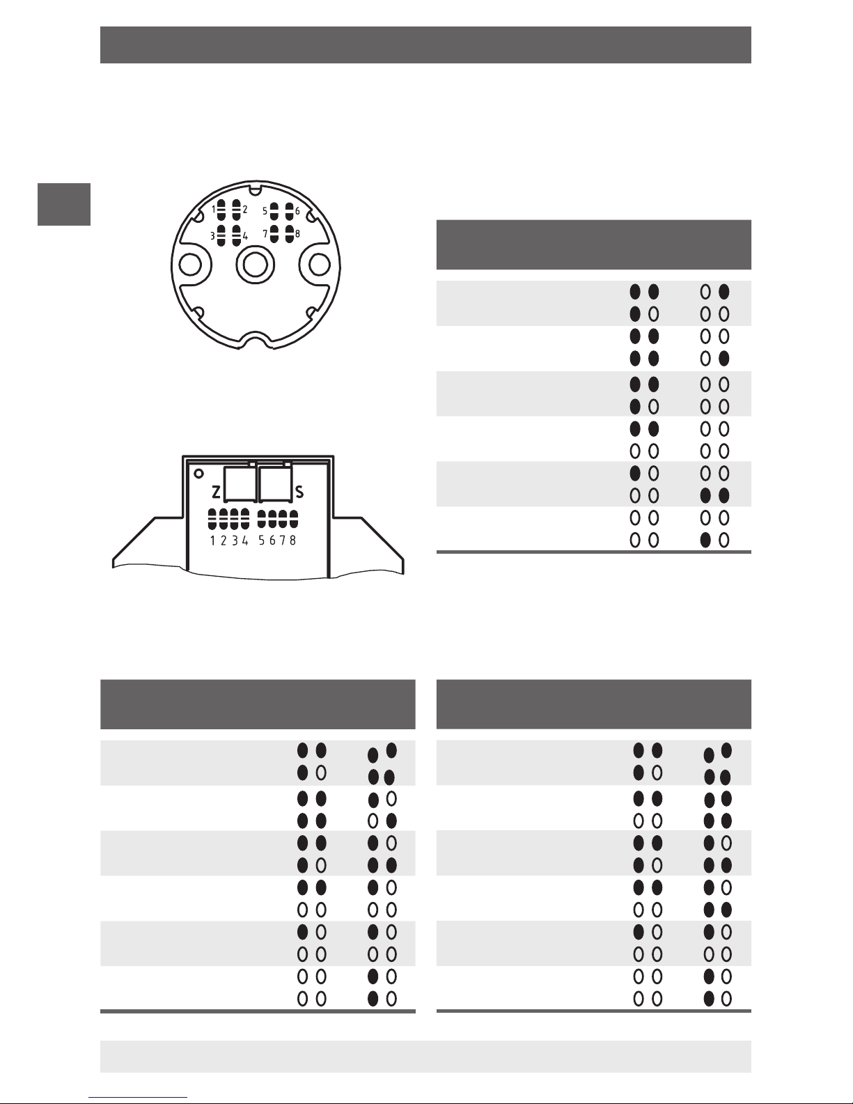
3.2 Position of solder bridges with Pt100
Head mounting:
Table 1: Model T19.10-1P0-1
Model T19.30-1P0-1
Table 2: Model T19.10-1P0-2
Model T19.30-1P0-2
Table 3: Model T19.10-1P0-3
Model T19.30-1P0-3
Rail mounting:
3. Conguration
1 2 5 6
3 4 7 8
1 2 5 6
3 4 7 8
1 2 5 6
3 4 7 8
1 2 5 6
3 4 7 8
1 2 5 6
3 4 7 8
1 2 5 6
3 4 7 8
1
2 5 6
3 4 7 8
1 2 5 6
3 4 7 8
1 2 5 6
3 4 7 8
1 2 5 6
3 4 7 8
1 2 5 6
3 4 7 8
1 2 5 6
3 4 7 8
1 2 5 6
3 4 7 8
1 2 5 6
3 4 7 8
1 2 5 6
3 4 7 8
1 2 5 6
3 4 7 8
1 2 5 6
3 4 7 8
1 2 5 6
3 4 7 8
Page 7

7
2143014.04 05/2010 GB/D
GB
WIKA Operating Instructions Temperature Transmitter T19
4. Mounting
4.1 Mounting for head mounting version
The transmitters for head mounting (Model T19.10) are designed to be
mounted on a measuring insert in a DIN connecting head with form B.
The connecting wires of the measuring insert must be approx. 50 mm
long and insulated.
Insert the measuring insert with the mounted transmitter in the protective
sheath and ax in the connecting head using screws in pressure springs.
2257521.022257521.03
4. Mounting
Mounting example:
Page 8

8
2143014.04 05/2010 GB/D
GB
WIKA Operating Instructions Temperature Transmitter T19
4.2 Mounting for rail mounting version
The transmitters for rail mounting (Model T19.30) are designed for
mounting on a standard rail or for wall mounting.
■
Rail mounting
The transmitter is axed without the use of auxiliary parts by sliding
onto a 35 mm top hat rail (DIN EN 50022-35).
De-mounting is done by freeing the snap parts.
■
Wall mounting
Lever the snap parts outwards with a screwdriver until they lock into
place. Mount case to the wall by means of two screws.
5. Electrical connections
In the case of the transmitters described here there is an
internal galvanic connection between the sensor input and
analogue output.
No external conducting is to be made (for example, by
earthing) between the connected temperature sensor and
analogue output!
We recommend the use of crimped connector sleeves in the
case of exible leads.
For Model T19.30 the connection cable of a temperature
probe must be shielded and grounded.
To connect a Pt100 sensor in a 2-wire connecting circuit:
Set a jumper between the input terminals 2 and 3 in accordance with
section 5.1.!
4. Mounting / 5. Electrical connections
Page 9

9
2143014.04 05/2010 GB/D
GB
WIKA Operating Instructions Temperature Transmitter T19
5.1 Sensor input Pt100/Pt1000
Head mounting version: Rail mounting version:
5.2 Connect 4 ... 20 mA-loop
The electrical connection of Model T19.10 (head mounting version) is
made through the ⊕ and ⊖ terminals, while Model T19.30 (rail mounting
version) is connected through the terminals 4 and 5 (please refer to
page 10).
■
Maximum permissible terminal voltage: 30 V
■
Maximum permissible load RA (dependent upon the loop power
supply voltage U
B
) 1000 Ω at 30 V power supply U
B
700 Ω at 24 V power supply U
B
RA ≤ (UB - 10 V ) / 0.02 A with RA in Ω and UB in V
6. Maintenance
The temperature transmitters described here are maintenance-free!
The electronics incorporate no components which could be repaired or
replaced. Depending upon operating conditions, it may be advisable to
check the adjustment yearly. Adjustment as per section 7.
InputInput
4 ... 20 mA-loop
5. Electrical connections / 6. Maintenance
Page 10

10
2143014.04 05/2010 GB/D
GB
WIKA Operating Instructions Temperature Transmitter T19
7. Adjustment of transmitter
The adjustment of the zero point and the span is carried out with
potentiometers. In order to adjust the transmitter output to optimal values
please adjust to the desired value by turning the potentiometer in one
direction only.
Example
Adjust the potentiometer in a clockwise direction.
The potentiometer has to be turned clockwise (the output current gets
higher) until the signal shows the desired value.
If the potentiometer is turned too much (the output current is too high),
the potentiometer must be turned back again until a value below the
desired value is reached (output current is too low). Adjust the potentiometer in a clockwise direction again until the desired value is reached.
Repeat steps as necessary.
Head mounting version: Rail mounting version:
Z S
Potentiometer
Z for zero point
S for span
7. Adjustment of transmitter
Page 11

11
2143014.04 05/2010 GB/D
GB
WIKA Operating Instructions Temperature Transmitter T19
7.1 Preparation
■
Connect a suitable simulation source to the input of the T19 (Pt100).
When simulating a Pt100 connect the simulator in a 3-wire connecting
circuit. We recommend the use of passive resistances. Electronical
simulation sources can cause incorrect measurement values.
■
Connect a mA meter in 4 ... 20 mA-loop according to section 5 (with
R
i
≤ max. permissible load!) to measure the output signal.
■
Connect a suitable power supply to the transmitter.
7.2 Adjustment
Carry out steps
through in the order given.
Set the lower value of the measurement range with the simulator, e.g.
-30 °C for measurement range -30 ... +50 °C.
Turn the zero potentiometer Z, until the output signal shows the
desired value.
Set the end value of the measurement range with the simulator, e.g.
+50 °C for measurement range -30 ... +50 °C.
Turn the span potentiometer S, until the output signal shows the
desired value.
High output currents (for example 20 mA) should therefore not exist
longer than 1 minute (in total) when doing adjustment. If adjustment
has to be repeated then allow the transmitter to cool down for approx.
20 minutes (disconnect the transmitter from the power supply).
Repeat step and check output signal of zero point.
Repeat step and check output signal of span.
7.3 Closing steps
Disconnect the simulator, the mA meter, and the power supply.
7. Adjustment of transmitter
Page 12

12
2143014.04 05/2010 GB/D
GB
WIKA Operating Instructions Temperature Transmitter T19
Page 13

D
WIKA Betriebsanleitung Temperatur-Transmitter T19
13
2143014.04 05/2010 GB/D
1. Sicherheitshinweise 14
1
2. Vor der Montage 14
3. Kongurieren 15
4. Montage 17
5. Elektrische Anschlüsse 18
6. Wartung 19
7.
Justieren 20
Inhalt
Inhalt
Warnung!
Dieses Symbol warnt Sie vor Handlungen, die Schäden an
Personen oder am Gerät verursachen können.
Page 14

D
WIKA Betriebsanleitung Temperatur-Transmitter T19
14
2143014.04 05/2010 GB/D
1. Sicherheitshinweise
Beachten Sie unbedingt bei Montage, Inbetriebnahme und
Betrieb dieser Transmitter die jeweils gültigen nationalen
Sicherheitsvorschriften (z. B.: VDE 100). Bei Nichtbeachten
der entsprechenden Vorschriften können schwere Körperverletzungen und/oder Sachschäden auftreten.
Nur entsprechend qualiziertes Personal darf an diesem
Gerät arbeiten.
Überprüfen Sie vor Inbetriebnahme die Eignung für die jeweilige
Anwendung. Beachten Sie insbesondere die im WIKA Datenblatt
TE 19.03 genannten zulässigen Umgebungs- und Betriebsbedingungen.
Verwenden Sie nur kongurierte Transmitter.
2. Vor der Montage
2.1 Transmitter mit Standardmessbereichen
Transmitter der Serie T19 mit Standardmessbereichen sind kongurierbar durch Lötbrücken. Die Lötbrücken sind zugänglich nach Abnahme
des Gehäusebodens. Montierte Transmitter müssen erst demontiert
werden, bevor konguriert werden kann.
Damit der Transmitter ordnungsgemäß arbeitet, muss er
konguriert sein. Bitte vergewissern Sie sich vor der Montage,
dass der Transmitter konguriert ist. Gegebenenfalls Konguration durchführen nach Kapitel 3.
Standardmessbereiche können optional werkseitig konguriert sein,
dann ist auf dem Typenschild der entsprechende Messbereich aufgedruckt. Werkseitig kongurierte Transmitter mit Standardmessbereich
können sofort an der Messstelle eingebaut und in Betrieb genommen
werden.
1. Sicherheitshinweise / 2. Vor der Montage
Page 15

D
WIKA Betriebsanleitung Temperatur-Transmitter T19
15
2143014.04 05/2010 GB/D
2.2 Transmitter mit Sondermessbereich
Transmitter der Serie T19 mit Sondermessbereich können nicht umkonguriert werden. Sondermessbereiche sind gekennzeichnet durch eine 9
an der letzten Stelle der Typbezeichnung: T19.x0-xx0-9
Sondermessbereiche sind werkseitig konguriert und können sofort an
der Messstelle eingebaut und in Betrieb genommen werden.
3. Kongurieren
3.1 Reihenfolge der Arbeitsschritte
Typ T19.10 Kopfversion:
Gehäuseboden abnehmen
Typ T19.30 Schienenversion:
Gehäusedeckel abnehmen
Lötbrücken für gewünschten
Messbereich setzen gemäß der
Tabellen 1 – 7. Die wählbaren
Messbereiche sind abhängig vom
Typ des Transmitters.
Typ T19.10: Gehäuseboden wieder aufsetzen
Typ T19.30: Gehäusedeckel wieder aufsetzen, Deckel mit seiner
Längsseite in das Gehäuse einsetzen, dann Deckel bis zum Einrasten aufdrücken
Nullpunkt und Spanne mit Potentiometer justieren gemäß Kapitel 7!
Messbereich auf Typenschild notieren (z. B. mit wasserfestem
Faserschreiber)
2. Vor der Montage / 3. Kongurieren
Darstellung: Typ T19.30
Mit kleinem Schraubendreher:
in Markierung einstechen
beide Einrastungen der Snap-In
Verbindung entriegeln
Page 16

Pt100-Messbereiche klein
Messbereich Lötbrücke
-50 ... +50 °C
0 ... +50 °C
0 ... +100 °C
0 ... +120 °C
0 ... +150 °C
0 ... +200 °C
Pt100-Messbereiche groß
Messbereich Lötbrücke
-50 ... +200 °C
0 ... +200 °C
0 ... +250 °C
0 ... +300 °C
0 ... +350 °C
0 ... +400 °C
Pt100-Messbereiche für HKL
Messbereich Lötbrücke
-30 ... +30 °C
-30 ... +50 °C
0 ... +60 °C
0 ... +80 °C
0 ... +100 °C
0 ... +120 °C
D
WIKA Betriebsanleitung Temperatur-Transmitter T19
16
2143014.04 05/2010 GB/D
3.2 Lage der Lötbrücken bei Pt100
Kopfversion:
1 2 5 6
3 4 7 8
1 2 5 6
3 4 7 8
1 2 5 6
3 4 7 8
1 2 5 6
3 4 7 8
1 2 5 6
3 4 7 8
1 2 5 6
3 4 7 8
Tabelle 1: Typ T19.10-1P0-1
Typ T19.30-1P0-1
Tabelle 2: Typ T19.10-1P0-2
Typ T19.30-1P0-2
1 2 5 6
3 4 7 8
1 2 5 6
3 4 7 8
1 2 5 6
3 4 7 8
1 2 5 6
3 4 7 8
1 2 5 6
3 4 7 8
1 2 5 6
3 4 7 8
1 2 5 6
3 4 7 8
1 2 5 6
3 4 7 8
1 2 5 6
3 4 7 8
1 2 5 6
3 4 7 8
1 2 5 6
3 4 7 8
1 2 5 6
3 4 7 8
Tabelle 3: Typ T19.10-1P0-3
Typ T19.30-1P0-3
Schienenversion:
3. Kongurieren
Page 17

D
WIKA Betriebsanleitung Temperatur-Transmitter T19
17
2143014.04 05/2010 GB/D
4. Montage
4.1 Montage bei Ausführung Kopfversion
Die Transmitter in Ausführung Kopfversion (Typ T19.10) sind vorgesehen
zur Montage auf einem Messeinsatz im DIN-Anschlusskopf der Form B.
Die Anschlussdrähte des Messeinsatzes müssen ca. 50 mm lang und
isoliert ausgeführt sein.
Messeinsatz mit montiertem Transmitter in die Schutzarmatur einstecken
und im Anschlusskopf mit Schrauben federnd befestigen.
2257521.022257521.03
4. Montage
Montagebeispiel:
Page 18

D
WIKA Betriebsanleitung Temperatur-Transmitter T19
18
2143014.04 05/2010 GB/D
4.2 Montage bei Ausführung Schienenversion
Die Transmitter in Ausführung Schienenversion (Typ T19.30) sind vorgesehen zur Montage auf einer Normschiene.
■
Montage auf Normschiene
Das Befestigen erfolgt ohne Hilfsmittel durch Aufrasten auf eine
35 mm Hutschiene (DIN EN 50022-35).
Demontage durch Entriegeln der Rastelemente.
■
Wandmontage
Mit Schraubendreher die Rastelemente bis zum Einrasten nach außen
hebeln. Gehäuse mit zwei Schrauben an der Wand montieren.
5. Elektrische Anschlüsse
Bei den hier beschriebenen Transmittern besteht intern
eine galvanische Verbindung von Sensoreingang und
Analogausgang.
Es darf keine äußere leitende Verbindung (z. B. über Erde)
zwischen angeschlossenem Temperatursensor und Analogausgang geben!
Bei Litzenadern empfehlen wir das Verwenden von
gecrimpten Adernendhülsen.
Das Anschlusskabel des Temperaturfühlers muss bei Typ
T19.30 geschirmt und geerdet sein.
Bei Anschluss eines Pt100-Sensors in 2-Leiter-Anschlussschaltung:
Setzen Sie eine Drahtbrücke zwischen den Eingangsklemmen 2 und 3
gemäß Kapitel 5.1!
4. Montage / 5. Elektrische Anschlüsse
Page 19

D
WIKA Betriebsanleitung Temperatur-Transmitter T19
19
2143014.04 05/2010 GB/D
5.1 Sensoreingang Pt100/Pt1000
Kopfversion: Schienenversion:
5.2 Anschluss der 4 ... 20 mA-Schleife
Der elektrische Anschluss erfolgt bei der Kopfversion Typ T19.10 über
die Anschlussklemmen ⊕ und ⊖ bzw. bei der Schienenversion Typ
T19.30 über die Klemmen 4 und 5 (siehe Seite 20).
■
Maximal zulässige Klemmenspannung: 30 V
■
Maximal zulässige Bürde RA (abhängig von Spannung UB der
Schleifenversorgung) 1000 Ω bei 30 V Hilfsenergie U
B
700 Ω bei 24 V Hilfsenergie U
B
RA ≤ (UB - 10 V) / 0,02 A mit RA in Ω und UB in V
6. Wartung
Die hier beschriebenen Temperatur-Transmitter sind wartungsfrei!
Die Elektronik enthält keinerlei Bauteile, welche repariert oder ausgetauscht werden könnten. Je nach Einsatzbedingungen empfehlen wir
eine jährliche Überprüfung der Justage gemäß Kapitel 7.
EingangEingang
4 ... 20 mA - Schleife
5. Elektrische Anschlüsse / 6. Wartung
Page 20

D
WIKA Betriebsanleitung Temperatur-Transmitter T19
20
2143014.04 05/2010 GB/D
7. Justieren der Transmitter
Die Justage von Nullpunkt und Spanne wird mit Potentiometern durchgeführt. Um die Transmitter optimal zu justieren empfehlen wir, den Sollwert
einseitig anzufahren.
Beispiel
Potentiometer im Uhrzeigersinn anfahren:
Potentiometer in Uhrzeigersinn drehen (Ausgangsstrom wird größer), bis
Ausgangssignal den gewünschten Wert hat.
Wurde das Potentiometer zu weit gedreht (Ausgangsstrom zu
groß), dann zuerst das Potentiometer wieder deutlich zurück drehen
(Ausgangsstrom ist jetzt wieder deutlich zu klein), anschließend den
gewünschten Ausgangsstrom erneut durch Drehen im Uhrzeigersinn
anfahren.
Kopfversion: Schienenversion:
Z S
Potentiometer
Z für Nullpunkt
S für Spanne
7. Justieren der Transmitter
Page 21

D
WIKA Betriebsanleitung Temperatur-Transmitter T19
21
2143014.04 05/2010 GB/D
7.1 Vorbereiten
■
An den Eingang des T19 eine geeignete Sensor-Simulationsquelle
anschließen (Pt100).
Bei Simulaton eines Pt 100-Sensors den Simulator in 3-Leiter-technik
anschließen. Wir empfehlen hierzu passive Widerstandsdekaden.
Elektronische Simulationsquellen können zu einer Verfälschung der
Messwerte führen.
■
In die 4 ... 20 mA-Schleife gemäß Kapitel 5 ein mA-Meter (mit
R
i
≤ max. zulässige Bürde!) zum Messen des Ausgangssignals
anschließen.
■
Transmitter mit Hilfsenergie versorgen.
7.2 Justieren
Arbeitsschritte
bis nacheinander durchführen.
Anfangswert des Messbereiches am Simulator einstellen, z. B. -30 °C
bei Messbereich -30 ... +50 °C.
Nullpunkts-Potentiometer Z solange drehen, bis Ausgangssignal den
gewünschten Wert hat.
Endwert des Messbereiches am Simulator einstellen, z. B. +50 °C bei
Messbereich -30 ... +50 °C.
Spanne-Potentiometer S solange drehen, bis Ausgangssignal den
gewünschten Wert hat.
Große Ausgangsströme (z. B. 20 mA) sollen bei der Justage nicht
länger als 1 Minute (in Summe) vorliegen. Muss die Justage wiederholt werden, so ist eine Abkühlzeit von ca. 20 Minuten einzuhalten
(Transmitter von der Hilfsenergie abklemmen).
Schritt wiederholen und Ausgangssignal des Nullpunktes
kontrollieren.
Schritt
wiederholen und Ausgangssignal der Spanne kontrollieren
.
7.3 Nachbereiten
Simulator, mA-Meter und Hilfsenergie abklemmen.
7. Justieren der Transmitter
Page 22

22
WIKA Operating Instructions Temperature Transmitter T19
2143014.04 05/2010 GB/D
WIKA Global
Europe
Austria
WIKA Messgerätevertrieb
Ursula Wiegand
GmbH & Co. KG
1230 Vienna
Tel. (+43) 1 86916-31
Fax: (+43) 1 86916-34
E-Mail: info@wika.at
www.wika.at
Benelux
WIKA Benelux
6101 WX Echt
Tel. (+31) 475 535-500
Fax: (+31) 475 535-446
E-Mail: info@wika.nl
www.wika.nl
Bulgaria
WIKA Bulgaria EOOD
Bul. „Al. Stamboliiski“ 205
1309 Soa
Tel. (+359) 2 82138-10
Fax: (+359) 2 82138-13
E-Mail: t.antonov@wika.bg
Croatia
WIKA Croatia d.o.o.
Hrastovicka 19
10250 Zagreb-Lucko
Tel. (+385) 1 6531034
Fax: (+385) 1 6531357
E-Mail: info@wika.hr
www.wika.hr
Finland
WIKA Finland Oy
00210 Helsinki
Tel. (+358) 9-682 49 20
Fax: (+358) 9-682 49 270
E-Mail: info@wika.
www.wika.
France
WIKA Instruments s.a.r.l.
95610 Eragny-sur-Oise
Tel. (+33) 1 343084-84
Fax: (+33) 1 343084-94
E-Mail: info@wika.fr
www.wika.fr
Germany
WIKA Alexander Wiegand
SE & Co. KG
63911 Klingenberg
Tel. (+49) 9372 132-0
Fax: (+49) 9372 132-406
E-Mail: info@wika.de
www.wika.de
Italy
WIKA Italia Srl & C. sas
20020 Arese (Milano)
Tel. (+39) 02 9386-11
Fax: (+39) 02 9386-174
E-Mail: info@wika.it
www.wika.it
Poland
WIKA Polska S.A.
87-800 Wloclawek
Tel. (+48) 542 3011-00
Fax: (+48) 542 3011-01
E-Mail: info@wikapolska.pl
www.wikapolska.pl
Romania
WIKA Instruments
Romania S.R.L.
Bucuresti, Sector 5
Calea Rahovei Nr.
266-268
Corp 61, Etaj 1
Tel. (+40) 21 4048327
Fax: (+40) 21 4563137
E-Mail: m.anghel@wika.ro
Russia
ZAO WIKA MERA
127015 Moscow
Tel. (+7) 495-648 01 80
Fax: (+7) 495-648 01 81
E-Mail: info@wika.ru
www.wika.ru
Serbia
WIKA Merna Tehnika
d.o.o.
Sime Solaje 15
11060 Belgrade
Tel. (+381) 11 2763722
Fax: (+381) 11 753674
E-Mail: info@wika.co.yu
www.wika.co.yu
Spain
Instrumentos WIKA, S.A.
C/Josep Carner, 11-17
08205 Sabadell
(Barcelona)
Tel. (+34) 902 902577
Fax: (+34) 933 938666
E-Mail: info@wika.es
www.wika.es
Page 23

23
WIKA Operating Instructions Temperature Transmitter T19
2143014.04 05/2010 GB/D
WIKA Global
Switzerland
Manometer AG
6285 Hitzkirch
Tel. (+41) 41 91972-72
Fax: (+41) 41 91972-73
E-Mail:
info@manometer.ch
www.manometer.ch
Turkey
WIKA Instruments Istanbul
Basinc ve Sicaklik Ölcme
Cihazlari
Ith. Ihr. ve Tic. Ltd. Sti.
Bayraktar Bulvari No. 21
34775 Yukari Dudullu Istanbul
Tel. (+90) 216 41590-66
Fax: (+90) 216 41590-97
E-Mail: info@wika.com.tr
www.wika.com.tr
Ukraine
WIKA Pribor GmbH
83016 Donetsk
Tel. (+38) 062 34534-16
Fax: (+38) 062 34534-17
E-Mail: info@wika.ua
www.wika.ua
United Kingdom
WIKA Instruments Ltd
Merstham, Redhill
RH13LG
Tel. (+44) 1737 644-008
Fax: (+44) 1737 644-403
E-Mail: info@wika.co.uk
www.wika.co.uk
North America
Canada
WIKA Instruments Ltd.
Head Oce
Edmonton, Alberta,
T6N 1C8
Tel. (+1) 780 46370-35
Fax: (+1) 780 46200-17
E-Mail: info@wika.ca
www.wika.ca
Mexico
Instrumentos WIKA
Mexico S.A.
de C.V.
01210 Mexico D.F.
Tel. (+52) 55 55466329
E-Mail: ventas@wika.com
www.wika.com.mx
USA
WIKA Instrument
Corporation
Lawrenceville, GA 30043
Tel. (+1) 770 5138200
Fax: (+1) 770 3385118
E-Mail: info@wika.com
www.wika.com
WIKA Instrument Corp.
Electrical Temperature
Division
950 Hall Court
Deer Park, TX 77536
Tel. (+1) 713 47500-22
Fax (+1) 713 47500-11
E-Mail:
info@wikaetemp.com
www.wika.com
Mensor Corporation
201 Barnes Drive
San Marcos, TX 78666
Tel. (+1) 512 3964200-15
Fax (+1) 512 3961820
E-Mail:
sales@mensor.com
www.mensor.com
South America
Argentina
WIKA Argentina S.A.
Buenos Aires
Tel. (+54) 11 47301800
Fax: (+54) 11 47610050
E-Mail: info@wika.com.ar
www.wika.com.ar
Brazil
WIKA do Brasil Ind. e
Com. Ltda.
CEP 18560-000 Iperó - SP
Tel. (+55) 15 34599700
Fax: (+55) 15 32661650
E-Mail:
marketing@wika.com.br
www.wika.com.br
Page 24

24
WIKA Alexander Wiegand SE & Co. KG
Alexander-Wiegand-Straße 30
63911 Klingenberg • Germany
Tel. (+49) 9372/132-0
Fax (+49) 9372/132-406
E-Mail info@wika.de
www.wika.de
2143014.04 05/2010 GB/D
WIKA Operating Instructions Temperature Transmitter T19
Technical alteration rights reserved.
Technische Änderungen vorbehalten.
Asia
China
WIKA International
Trading (Shanghai)
Co., Ltd.
200001 Shanghai
Tel. (+86) 21 538525-72
Fax: (+86) 21 538525-75
E-Mail: info@wika.com.cn
www. wika.com.cn
India
WIKA Instruments India
Pvt. Ltd.
Village Kesnand, Wagholi
Pune - 412 207
Tel. (+91) 20 66293-200
Fax: (+91) 20 66293-325
E-Mail: sales@wika.co.in
www.wika.co.in
Japan
WIKA Japan K. K.
Tokyo 105-0023
Tel. (+81) 3 543966-73
Fax: (+81) 3 543966-74
E-Mail:
t-shimane@wika.co.jp
Weitere WIKA Niederlassungen weltweit nden Sie online unter
www.wika.de.
Further WIKA subsidiaries worldwide can be found online at
www.wika.de.
WIKA Global
Kazakhstan
TOO WIKA Kazakhstan
050050 Almaty
Tel. (+7) 32 72330848
Fax: (+7) 32 72789905
E-Mail: info@wika.kz
www.wika.kz
Korea
WIKA Korea Ltd.
#569-21 Gasan-dong
Seoul 153-771 Korea
Tel. (+82) 2 869 05 05
Fax (+82) 2 869 05 25
E-Mail: info@wika.co.kr
www.wika.co.kr
 Loading...