

Page 1
Operating instructions
Betriebsanleitung
EN
DE
Digital temperature transmitter, model T16
Digitaler Temperaturtransmitter, Typ T16
Head mounting version, model T16.H Rail mounting version, model T16.R
Page 2

EN
DE
2
14147933.02 10/2018 EN/DE
WIKA operating instructions model T16
Operating instructions model T16 Page 3 - 36
Betriebsanleitung Typ T16 Seite 37 - 65
Further languages can be found at www.wika.com.
© 06/2017 WIKA Alexander Wiegand SE & Co. KG
All rights reserved. / Alle Rechte vorbehalten.
WIKA
®
is a registered trademark in various countries.
WIKA
®
ist eine geschützte Marke in verschiedenen Ländern.
Prior to starting any work, read the operating instructions!
Keep for later use!
Vor Beginn aller Arbeiten Betriebsanleitung lesen!
Zum späteren Gebrauch aufbewahren!
Page 3

EN
Contents
Contents
1. General information 5
2. Design and function 6
2.1 Description. . . . . . . . . . . . . . . . . . . . . . . . . . . 6
2.2 Dimensions in mm . . . . . . . . . . . . . . . . . . . . . . . . 6
2.3 Scope of delivery . . . . . . . . . . . . . . . . . . . . . . . . 7
3. Safety 8
3.1 Explanation of symbols . . . . . . . . . . . . . . . . . . . . . . 8
3.2 Intended use . . . . . . . . . . . . . . . . . . . . . . . . . . 8
3.3 Responsibility of the operator . . . . . . . . . . . . . . . . . . . . 9
3.4 Personnel qualification. . . . . . . . . . . . . . . . . . . . . . . 9
3.5 Labelling, safety marks . . . . . . . . . . . . . . . . . . . . . . 10
3.6 Ex marking. . . . . . . . . . . . . . . . . . . . . . . . . . . 11
4. Transport, packaging and storage 12
4.1 Transport . . . . . . . . . . . . . . . . . . . . . . . . . . . 12
4.2 Packaging and storage . . . . . . . . . . . . . . . . . . . . . . 12
5. Commissioning, operation 13
5.1 Grounding . . . . . . . . . . . . . . . . . . . . . . . . . . . 13
5.2 Mounting . . . . . . . . . . . . . . . . . . . . . . . . . . . 15
5.2.1 Transmitter in head mounting version (model T16.H) . . . . . . . . . . . 15
5.2.2 Transmitter in rail mounting version (model T16.R) . . . . . . . . . . . . 16
5.3 Electrical connection . . . . . . . . . . . . . . . . . . . . . . . 16
5.3.1 Power supply, 4 ... 20 mA current loop . . . . . . . . . . . . . . . . 17
5.3.2 Sensors . . . . . . . . . . . . . . . . . . . . . . . . . . . 18
5.4 Configuration . . . . . . . . . . . . . . . . . . . . . . . . . . 19
5.4.1 Configurable monitoring functionality . . . . . . . . . . . . . . . . . 19
5.4.2 Configuration via the PC . . . . . . . . . . . . . . . . . . . . . 19
5.4.3 Programming unit model PU-548 . . . . . . . . . . . . . . . . . . 20
5.4.4 Configuration software WIKAsoft-TT . . . . . . . . . . . . . . . . . 20
6. Special conditions for safe use (X conditions) 21
6.1 Approval ATEX und IECEx . . . . . . . . . . . . . . . . . . . . . 21
6.1.1 Models T16.x-AC, T16.x-AI . . . . . . . . . . . . . . . . . . . . 21
6.1.2 Model T16.x-AN . . . . . . . . . . . . . . . . . . . . . . . . 21
6.1.3 Model T16.x-AE . . . . . . . . . . . . . . . . . . . . . . . . 21
6.2 Approval FM . . . . . . . . . . . . . . . . . . . . . . . . . . 22
6.2.1 Models T16.x-AC, T16.x-AI . . . . . . . . . . . . . . . . . . . . 22
6.2.2 Model T16.x-AN . . . . . . . . . . . . . . . . . . . . . . . . 22
6.2.3 Model T16.x-AE . . . . . . . . . . . . . . . . . . . . . . . . 22
14147933.02 10/2018 EN/DE
WIKA operating instructions model T16
3
Page 4

EN
Contents
Declarations of conformity can be found online at www.wika.com.
7. Conguration software WIKAsoft-TT 23
7.1 Starting the software . . . . . . . . . . . . . . . . . . . . . . . 23
7.2 Configuration procedure . . . . . . . . . . . . . . . . . . . . . . 24
7.3 Fault diagnosis . . . . . . . . . . . . . . . . . . . . . . . . . 24
7.4 Measured values. . . . . . . . . . . . . . . . . . . . . . . . . 24
7.5 Configuring several instruments identically . . . . . . . . . . . . . . . . 24
8. Faults 25
9. Maintenance 27
10. Return and disposal 27
10.1 Return . . . . . . . . . . . . . . . . . . . . . . . . . . . . 27
10.2 Disposal . . . . . . . . . . . . . . . . . . . . . . . . . . . 27
11. Specications 28
11.1 Safety-related characteristic values for models T16.x-AI, T16.x-AC. . . . . . . . 29
11.2 Safety-related characteristic values for models T16.x-AN, T16.x-AE . . . . . . . 30
11.3 Versioning per NAMUR NE53 . . . . . . . . . . . . . . . . . . . . 31
12. Accessories 31
Appendix 1: Control drawing CSA/FM 32
Appendix 2: EU declaration of conformity 36
14147933.02 10/2018 EN/DE
WIKA operating instructions model T16
4
Page 5

EN
1. General information
14147933.02 10/2018 EN/DE
WIKA operating instructions model T16
5
1. General information
■
The temperature transmitter described in the operating instructions has been designed
and manufactured using state-of-the-art technology. All components are subject
to stringent quality and environmental criteria during production. Our management
systems are certified to ISO 9001 and ISO 14001.
■
These operating instructions contain important information on handling the instrument.
Working safely requires that all safety instructions and work instructions are observed.
■
Observe the relevant local accident prevention regulations and general safety
regulations for the instrument's range of use.
■
The operating instructions are part of the product and must be kept in the immediate
vicinity of the instrument and readily accessible to skilled personnel at any time. Pass
the operating instructions on to the next operator or owner of the instrument.
■
Skilled personnel must have carefully read and understood the operating instructions
prior to beginning any work.
■
The general terms and conditions contained in the sales documentation shall apply.
■
Subject to technical modifications.
■
Further information:
- Internet address: www.wika.de / www.wika.com
- Relevant data sheet:
TE 16.01
- Application consultant:
Tel.: +49 9372 132-0
Fax: +49 9372 132-406
info@wika.de
Page 6

EN
2. Design and function
14147933.02 10/2018 EN/DE
WIKA operating instructions model T16
6
2. Design and function
2.1 Description
The model T16 temperature transmitter is used for converting a thermoelectric voltage into
a proportional current signal (4 ... 20 mA). Thus the sensors are permanently monitored for
their fault-free operation.
The temperature transmitter meets the requirements for:
■
Explosion protection (depending on the version)
■
Electromagnetic compatibility in accordance with NAMUR recommendation NE21
■
Signalling at the analogue output in accordance with NAMUR recommendation NE43
■
Sensor break signalling in accordance with NAMUR recommendation NE89 (corrosion
monitoring sensor connection)
2.2 Dimensions in mm
■
Head mounting version, model T16.H
14263238.01
Page 7

EN
2. Design and function
14147933.02 10/2018 EN/DE
WIKA operating instructions model T16
7
■
Rail mounting version, model T16.R
14263238.01
2.3 Scope of delivery
Cross-check scope of delivery with delivery note.
Page 8

EN
3. Safety
14147933.02 10/2018 EN/DE
WIKA operating instructions model T16
8
3. Safety
3.1 Explanation of symbols
WARNING!
... indicates a potentially dangerous situation that can result in serious injury
or death, if not avoided.
CAUTION!
... indicates a potentially dangerous situation that can result in light injuries or
damage to property or the environment, if not avoided.
DANGER!
... identifies hazards caused by electrical power. Should the safety
instructions not be observed, there is a risk of serious or fatal injury.
DANGER!
... indicates a potentially dangerous situation in the hazardous area that can
result in serious injury or death, if not avoided.
Information
... points out useful tips, recommendations and information for efficient and
trouble-free operation.
3.2 Intended use
The model T16 temperature transmitter is a universal transmitter, configurable via a PC, for
use with thermocouples.
The instrument has been designed and built solely for the intended use described here,
and may only be used accordingly.
The technical specifications contained in these operating instructions must be observed.
Improper handling or operation of the instrument outside of its technical specifications
requires the instrument to be taken out of service immediately and inspected by an
authorised WIKA service engineer.
The manufacturer shall not be liable for claims of any type based on operation contrary to
the intended use.
Page 9

EN
3. Safety
14147933.02 10/2018 EN/DE
WIKA operating instructions model T16
9
3.3 Responsibility of the operator
The instrument is used in the industrial sector. The operator is therefore responsible for
legal obligations regarding safety at work.
The safety instructions within these operating instructions, as well as the safety, accident
prevention and environmental protection regulations for the application area must be
maintained.
The operator is obliged to maintain the product label in a legible condition.
The responsibility for classification of zones lies with the plant operator and not the
manufacturer/supplier of the equipment.
3.4 Personnel qualification
WARNING!
Risk of injury should qualification be insufficient
Improper handling can result in considerable injury and damage to
equipment.
▶
The activities described in these operating instructions may only be
carried out by skilled electrical personnel who have the qualifications
described below.
Skilled electrical personnel
Skilled electrical personnel are understood to be personnel who, based on their technical
training, know-how and experience as well as their knowledge of country-specific
regulations, current standards and directives, are capable of carrying out work on
electrical systems and independently recognising and avoiding potential hazards. The
skilled electrical personnel have been specifically trained for the work environment they
are working in and know the relevant standards and regulations. The skilled electrical
personnel must comply with current legal accident prevention regulations.
Special knowledge for working with instruments for hazardous areas:
The skilled electrical personnel must have knowledge of ignition protection types,
regulations and provisions for equipment in hazardous areas.
Special operating conditions require further appropriate knowledge, e.g. of aggressive
media.
Page 10
EN
3. Safety
T16.H-AIZZZ
0158
S# 1106FIDB159
V 1.0.0 2015-12
DC 8 ... 30 V
TAG-NR.
WIKA A. Wiegand SE & Co. KG D-63911 Klingenberg
Pt100/3 -150 ... +180 °C
Made in Germany
BVS 15 ATEX E 139 X
IECEx BVS 15.0112X
II 1 G Ex ia IIC T6...T4 Ga
II 1 D Ex ia IIIC T135 °C Da
Tamb T4/T5/T6: -40 ... +85/70/55 °C
T16.R-AIZZZ
S# 1106FIDB159
V 1.0.0
DC 8 ... 30 V
TAG-NR.
Pt100/3 -150 ... +180 °C
Sensor
mA-Loop
T16.H-AIZZZ
0158
S# 1106FIDB159
V 1.0.0 2015-12
DC 8 ... 30 V
TAG-NR.
WIKA A. Wiegand SE & Co. KG D-63911 Klingenberg
Pt100/3 -150 ... +180 °C
Made in Germany
BVS 15 ATEX E 139 X
IECEx BVS 15.0112X
II 1 G Ex ia IIC T6...T4 Ga
II 1 D Ex ia IIIC T135 °C Da
Tamb T4/T5/T6: -40 ... +85/70/55 °C
T16.H-AIZZZ
0158
S# 1106FIDB159
V 1.0.0 2015-12
DC 8 ... 30 V
TAG-NR.
WIKA A. Wiegand SE & Co. KG D-63911 Klingenberg
Pt100/3 -150 ... +180 °C
Made in Germany
BVS 15 ATEX E 139 X
IECEx BVS 15.0112X
II 1 G Ex ia IIC T6...T4 Ga
II 1 D Ex ia IIIC T135 °C Da
Tamb T4/T5/T6: -40 ... +85/70/55 °C
T16.R-AIZZZ
S# 1106FIDB159
V 1.0.0
DC 8 ... 30 V
TAG-NR.
Pt100/3 -150 ... +180 °C
Sensor
mA-Loop
T16.R-AIZZZ
0158
S# 1106FIDB159
V 1.0.0 2015-12
DC 8 ... 30 V
TAG-NR.
WIKA A. Wiegand SE & Co. KG D-63911 Klingenberg
Pt100/3
-150 ... +180 °C
Made in Germany
BVS 15 ATEX E 139 X
IECEx BVS 15.0112X
II 2(1)G Ex ia [ia Ga] IIC T6...T4 Ga
II 2(1)D Ex ia [ia Da] IIIC T135 °C Da
Tamb T4/T5/T6: -40 ... +85/70/55 °C
1
2
3
4
2
3
4
2
3
Resistance sensor
14147933.02 10/2018 EN/DE
WIKA operating instructions model T16
10
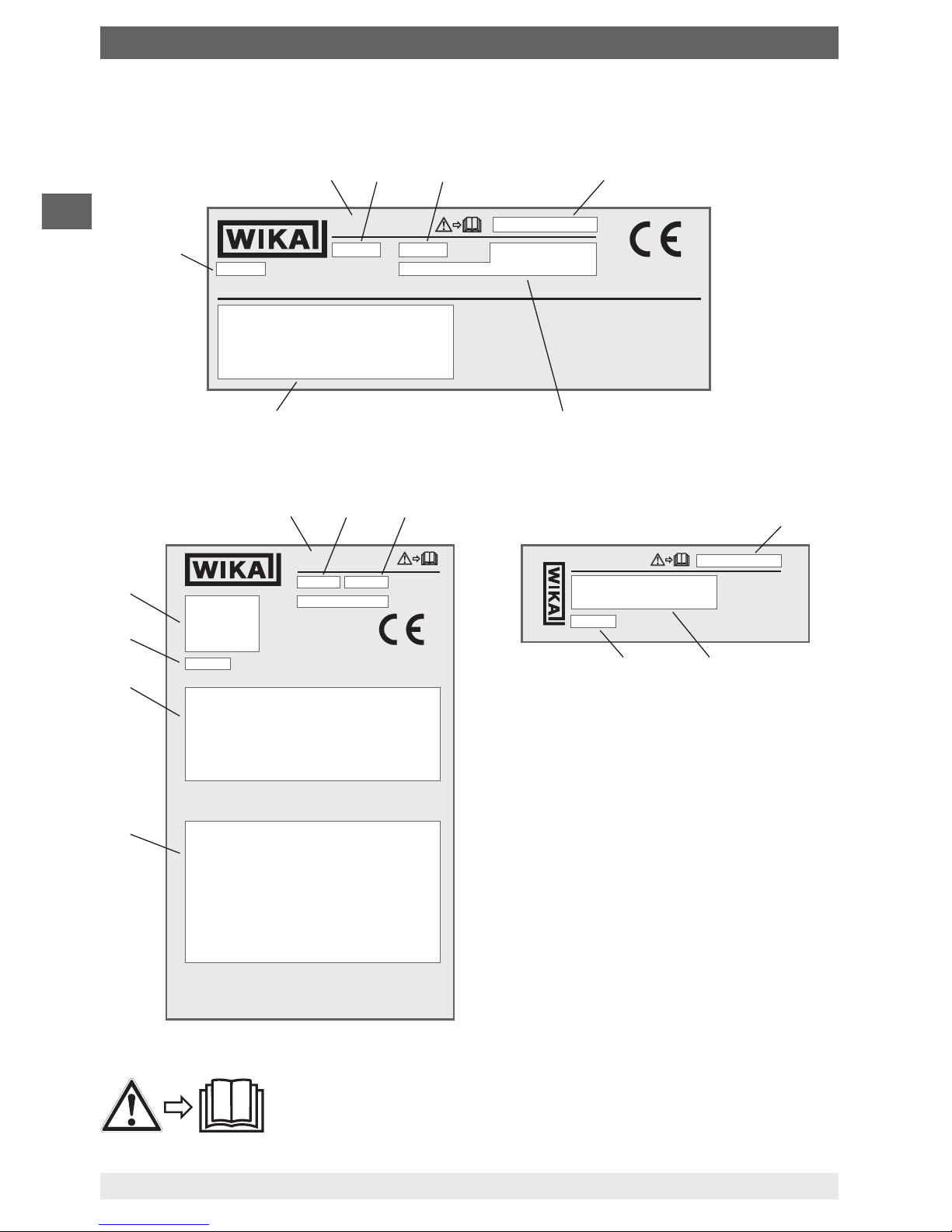
3.5 Labelling, safety marks
■
Head mounting version, model T16.H
■
Rail mounting version, model T16.R
Before mounting and commissioning the instrument, ensure you
read the operating instructions!
Model
Firmware
Date of manufacture (year-month)
Serial number
Sensor information (model, connection
method, power supply, measuring range)
Approval-related data
TAG no.
Pin assignment
Page 11

EN
3. Safety
14147933.02 10/2018 EN/DE
WIKA operating instructions model T16
11
3.6 Ex marking
DANGER!
Danger to life due to loss of explosion protection
Non-observance of these instructions and their contents may result in the
loss of explosion protection.
▶
Observe the safety instructions and further explosion instructions in these
operating instructions.
▶
Follow the requirements of the ATEX directive.
▶
Observe the information given in the applicable type examination
certificate and the relevant country-specific regulations for installation and
use in hazardous areas (e.g. IEC 60079-14, NEC, CEC).
Check whether the classification is suitable for the application. Observe the relevant
national regulations.
Model overview of European approvals
Model Ex marking Ignition protection type
BVS 17
ATEX E039 X
IECEx BVS 17.0033X
T16.H-AI
(Head mounting version)
II 1G
II 1D
Ex ia IIC T6 ... T4 Ga
Ex ia IIIC T135 °C Da
Intrinsically safe equipment
T16.R-AI
(Rail mounting version)
II 2(1)G
II 2(1)D
Ex ia [ia Ga] IIC T6 ... T4 Gb
Ex ia [ia Da] IIIC T135 °C Db
Intrinsically safe equipment
T16.x-AC II 3G Ex ic IIC T6 ... T4 Gc X Intrinsically safe equipment
T16.x-AN II 3G Ex nA IIC T6 ... T4 Gc X Non-incendive equipment
T16.x-AE II 3G Ex ec IIC T6 ... T4 Gc Non-incendive equipment
Page 12

EN
4. Transport, packaging and storage
14147933.02 10/2018 EN/DE
WIKA operating instructions model T16
12
4. Transport, packaging and storage
4.1 Transport
Check the instrument for any damage that may have been caused by transport.
Obvious damage must be reported immediately.
CAUTION!
Damage through improper transport
With improper transport, damage to property can occur.
▶
Do not use transmitters with any damage to the exterior!
If the instrument is transported from a cold into a warm environment, the formation of
condensation may result in instrument malfunction. Before putting it back into operation,
wait for the instrument temperature and the room temperature to equalise.
4.2 Packaging and storage
Do not remove packaging until just before mounting.
Permissible conditions at the place of storage:
■
Storage temperature: -40 ... +85 °C
■
Humidity: 95 % r. h. (condensation permitted)
Avoid exposure to the following factors:
■
Direct sunlight or proximity to hot objects
■
Mechanical vibration, mechanical shock (putting it down hard)
■
Soot, vapour, dust and corrosive gases
Page 13

EN
5. Commissioning, operation
14147933.02 10/2018 EN/DE
WIKA operating instructions model T16
13
5. Commissioning, operation
Personnel: Skilled electrical personnel
Tools: Screwdriver (see chapter 5.3 “Electrical connection”)
DANGER!
Danger to life from explosion!
Through working in flammable atmospheres, there is a risk of explosion
which can cause death.
▶
Only carry out set-up work in non-hazardous environments!
▶
In hazardous areas, only use temperature transmitters that are approved
for those hazardous areas. Observe the approvals on the product label.
5.1 Grounding
WARNING!
Prevention of electrostatic discharge
When working during a running process operation, measures to prevent
electrostatic discharge from the connection terminals should be taken, as a
discharge could lead to temporary corruption of the measured value.
▶
Only use model T16.H temperature transmitters in grounded thermometer
heads!
▶
Connection of a thermocouple (e.g. type K) to the T16.R with a shielded
cable. The shield must be electrically connected to the case of the
grounded thermometer.
Connection head BSZ
grounded
Loop cable
Only use the model T16
temperature transmitter in
grounded thermometers!
Page 14
EN
5. Commissioning, operation
14147933.02 10/2018 EN/DE
WIKA operating instructions model T16
14
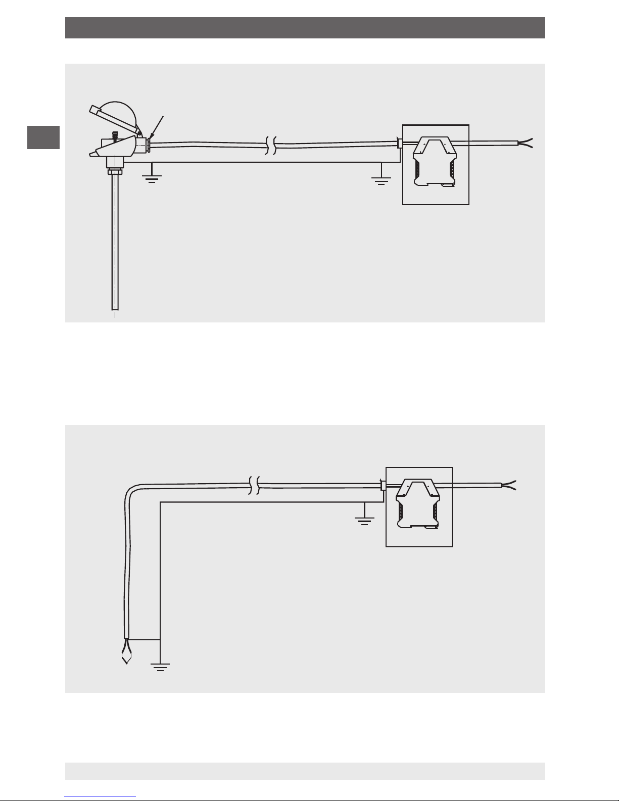
In applications with higher EMC requirements, using a shielded cable between the
transmitter and the sensor is recommended, especially in connection with long leads to the
sensor. For an exemplary illustration, see drawing.
With the rail mounting version (T16.R) and cable lengths greater than 30 m, shielded cable
must be used.
grounded
grounded shield
Sensor wire
Equipotential bonding
Field case/
Control cabinet
Sensor
T16
Connection head BSZ
grounded
grounded shield
Thermowell
with sensor
grounded
Sensor wire
Equipotential bonding
T16
Field case/
Control cabinet
Page 15
EN
5. Commissioning, operation
14147933.02 10/2018 EN/DE
WIKA operating instructions model T16
15
5.2 Mounting
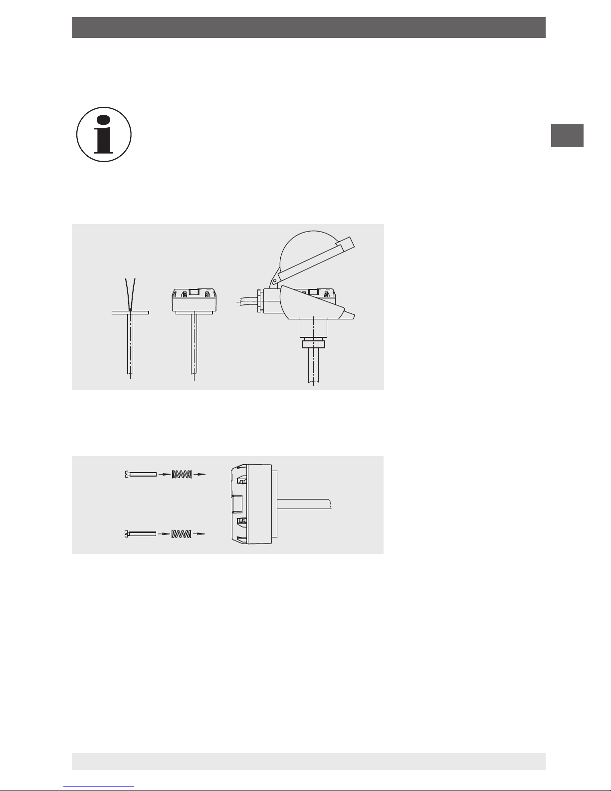
5.2.1 Transmitter in head mounting version (model T16.H)
When fitting the head-mounted version of the transmitter, do not exceed a
torque of 1 Nm!
The transmitters for head mounting version are designed to be mounted on a measuring
insert within a form B, DIN connection head. The connection wires of the measuring insert
must be approx. 50 mm long and insulated.
Mounting in connection head
Insert the measuring insert with the mounted transmitter into the protective components
and secure into the connection head using screws in pressure springs.
Mounting in the connection head cover
When mounting in the cover of a connection head, use suitable screws and matching
washers.
Installing with DIN rail adapter
With the mechanical adapter, available as an accessory, the T16.H head-mounted
transmitters can also be fixed on a DIN rail (see chapter 12 “Accessories”).
Mounting example
14139114.01
14139114.01
Page 16
EN
5. Commissioning, operation
14147933.02 10/2018 EN/DE
WIKA operating instructions model T16
16
5.2.2 Transmitter in rail mounting version (model T16.R)
The rail mounting case will fasten onto a 35 mm DIN rail (EN 60175) by simply locking it
into place without the need for any tools.
Disassembly involves unlocking the detent element.
5.3 Electrical connection
DANGER!
Danger to life caused by electric current
Upon contact with live parts, there is a direct danger to life.
▶
The instrument may only be installed and mounted by skilled personnel.
▶
Operation using a defective power supply unit (e.g. short circuit from the
mains voltage to the output voltage) can result in life-threatening voltages
at the instrument!
▶
Carry out mounting work only with power disconnected.
▶
The connected wires must be checked to ensure they are connected
properly. Only well-secured wires can guarantee a fault-free operation.
This is protection class 3 equipment for connection at low voltages, which are separated
from the power supply or voltages of greater than AC 50 V or DC 120 V. Preferably, a
connection to an SELV or PELV circuit is recommended; alternatively protective measures
from HD 60346-4-41 (DIN VDE 0100-410).
Alternatively for North America
The connection can be made in line with “Class 2 Circuits” or “Class 2 Power Units” in
accordance with CEC (Canadian Electrical Code) or NEC (National Electrical Code).
The functional galvanic isolation present in the instrument does not ensure sufficient
protection against electrical impulses in the sense of EN 61140.
Recommended tool for screw terminals
Model Screwdriver Tightening torque
T16.H Cross head (Pozidriv tip), size 2 (ISO 8764) 0.5 Nm
T16.R Slotted, 3 x 0.5 mm (ISO 2380) 0.5 Nm
Page 17
EN
5. Commissioning, operation
14147933.02 10/2018 EN/DE
WIKA operating instructions model T16
17
5.3.1 Power supply, 4 ... 20 mA current loop
The model T16 is a 2-wire, powered temperature transmitter. Depending on the version, it
can be supplied with various types of power supply.
With flexible leads we recommend the use of crimped connector sleeves.
The integrated reverse polarity protection (wrong polarity on the terminals ⊕ and ⊖)
prevents the transmitter from being damaged.
Maximum values
■
Model T16.x-ZZ: DC 35 V
■
Model T16.x-AI: DC 30 V
■
Model T16.x-AC: DC 30 V
■
Model T16.x-AN: DC 35 V
■
Model T16.x-AE: DC 35 V
Minimum terminal voltage
DC 10 V
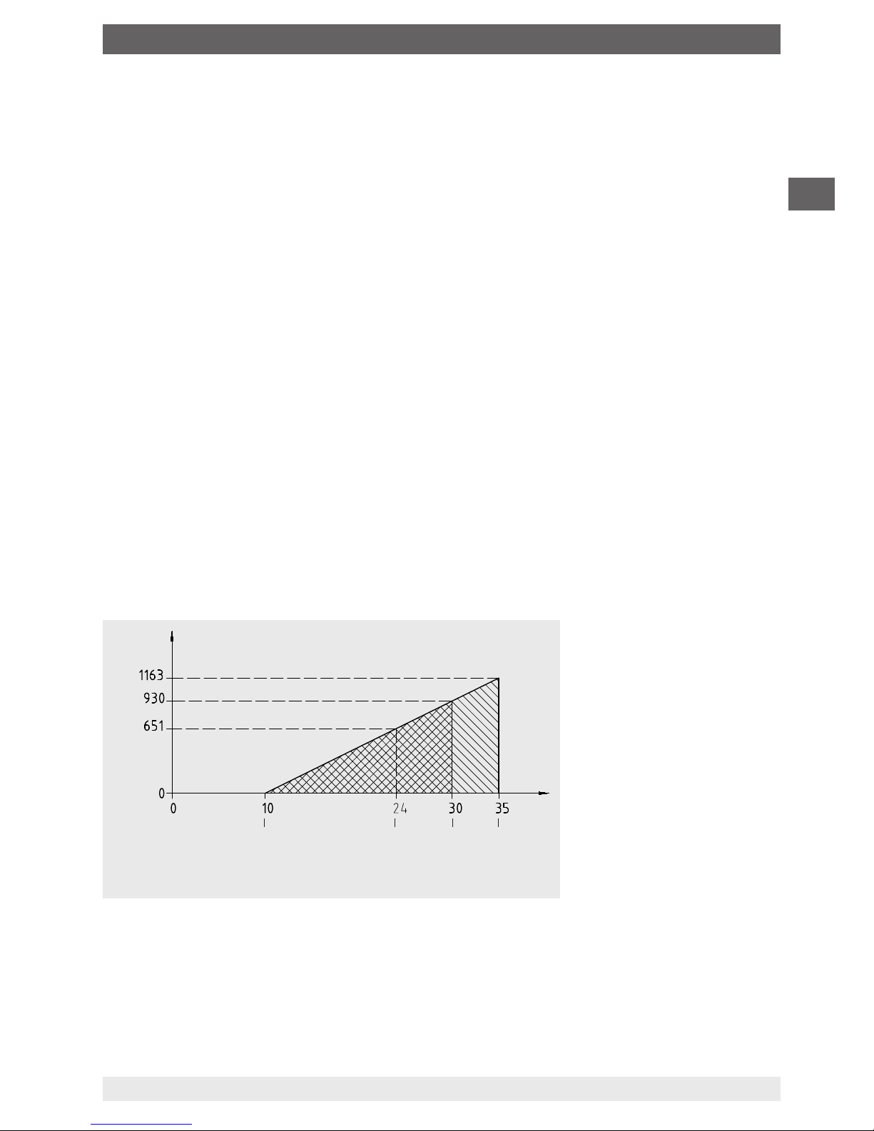
The load must not be too high, as otherwise, in the case of relatively high currents, the
terminal voltage at the transmitter will be too low.
Maximum permissible load depending on the supply voltage
Load diagram
Voltage UB in V
Load R
A
in Ω
14222396.01
Min. voltage
Operating
voltage
Ex instruments
Non-Ex
instruments
Page 18

EN
5. Commissioning, operation
14147933.02 10/2018 EN/DE
WIKA operating instructions model T16
18
5.3.2 Sensors
Designation of connection terminals
Thermocouples (TC)
It is possible to connect a thermocouple in a 2-wire connection.
The T16 transmitter always uses the internal cold junction.
For the safety-relevant maximum values for the connection of the voltage
supply and the sensors, see chapter 11 “Specifications”.
Thermocouples
Input
Output
4 ... 20 mA loop
T16.H T16.R
Connection of the
PU-548 programming unit
14151201.01
Page 19

EN
5. Commissioning, operation
14147933.02 10/2018 EN/DE
WIKA operating instructions model T16
19
5.4 Configuration
Configurable are
■
Sensor type
■
Measuring range
■
Unit
■
Signalling
■
Measuring range monitoring
■
Damping
■
Write protection
■
“Several” TAG numbers
■
2-point scaling
The temperature transmitters are delivered with a basic configuration (see data sheet
TE 16.01) or configured according to customer specifications. If the configuration is
changed afterwards, the modifications must be noted on the product label using a waterresistant fibre-tip pen.
A simulation of the input value is not required to configure the T16. A sensor
simulation is only required for the functional test.
5.4.1 Configurable monitoring functionality
Measuring range monitoring:
If this function is activated, an error is signalled on the current loop if the measured value is
either below or over the limits of the measuring range.
5.4.2 Configuration via the PC
Configuration is carried out using a USB interface with a PC via the model PU-548
programming unit (see chapter 12 “Accessories”) and the WIKAsoft-TT configuration
software.
The required Windows device driver for the PU-548 is a component of the
current Windows
®
operating system.
Windows® is a registered trademark of Microsoft Corporation in the United States and other countries.
Page 20

EN
5. Commissioning, operation
14147933.02 10/2018 EN/DE
WIKA operating instructions model T16
20
5.4.3 Programming unit model PU-548
■
Easy to use
■
LED status indicator
■
Compact design
■
No further voltage supply is needed for either the
programming unit or for the transmitter
■
No driver installation needed (Windows® standard drivers are used)
(replaces programming unit model PU-448)
Connection of the PU-548
5.4.4 Configuration software WIKAsoft-TT
The WIKAsoft-TT configuration software is regularly updated and adapted to the firmware
extensions of the T16. Thus, full access to all functionalities and parameters of the
transmitter is permanently ensured (see chapter 7 “Configuration software WIKAsoft-TT”).
Free download of the current version of the WIKAsoft-TT software at
www.wika.com.
Head mounting version,
model T16.H
Rail mounting version, model T16.R
Page 21

EN
6. Special conditions for safe use (X conditions)
14147933.02 10/2018 EN/DE
WIKA operating instructions model T16
21
6. Special conditions for safe use (X conditions)
The influence of power dissipation of other devices placed beside the transmitter has
to be taken into account with regard to a temperature rise of the transmitter’s ambient
temperature.
General information:
Transmitters with “ia” marking may also be used in supply circuits of type “ib” with the same
connection parameters. Thus the entire measuring circuit (including the sensor circuit) is an
“ib” circuit. Transmitters were operated with supply circuits of type “ib” may not be re-used
with supply circuits of type “ia”.
6.1 Approval ATEX and IECEx
6.1.1 Models T16.x-AC, T16.x-AI
■
The transmitter shall be mounted in an enclosure in accordance with IEC 60079-11
suitable for the relevant installation area. The enclosure has to fulfil at least IP20 for
areas requiring EPL Ga, Gb or Gc and IP54 in accordance with IEC 60079-0 for areas
requiring EPL Db or Dc.
■
During the installation internal wiring, clearances, creepage distances and separations
have to be considered according to IEC 60079-11.
6.1.2 Model T16.x-AN
■
The transmitter shall be mounted in an enclosure fulfilling at least IP54 in accordance
with IEC 60079-0 and IEC 60079-15.
■
During the installation clearances, creepage distances and separations have to be
considered according to IEC 60079-15.
■
The equipment shall only be used in an area of at least pollution degree 2, as defined in
IEC 60664-1.
■
Maximum overvoltage category II according to IEC 60664-1 is permitted for the circuits.
6.1.3 Model T16.x-AE
■
The transmitter shall be mounted in an enclosure fulfilling at least IP54 in accordance
with IEC 60079-0 and IEC 60079-7.
■
During the installation clearances, creepage distances and separations have to be
considered according to IEC 60079-7.
■
The equipment shall only be used in an area of at least pollution degree 2, as defined in
IEC 60664-1.
■
Maximum overvoltage category II according to IEC 60664-1 is permitted for the circuits.
Page 22

EN
6. Special conditions for safe use (X conditions)
14147933.02 10/2018 EN/DE
WIKA operating instructions model T16
22
6.2 Approval FM
6.2.1 Models T16.x-AC, T16.x-AI
■
The transmitters shall be mounted in an enclosure in accordance with
ANSI/ISA 60079-11 suitable for the relevant installation area. The enclosure has to fulfil
at least IP20.
■
During the installation internal wiring, clearances, creepage distances and separations
have to be considered according to ANSI/ISA 60079-11.
6.2.2 Model T16.x-AN
■
The transmitters shall be mounted in an enclosure fulfilling at least IP54 in accordance
with ANSI/ISA 60079-0 and ANSI/ISA 60079-15.
■
During the installation clearances, creepage distances and separations have to be
considered according to ANSI/ISA 60079-15.
■
The equipment shall only be used in an area of at least pollution degree 2, as defined in
ANSI/ISA 61010-1 resp. IEC 60664-1.
■
Maximum overvoltage category II in accordance with ANSI/ISA 61010-1 resp.
IEC 60664-1 is permitted for the circuits.
6.2.3 Model T16.x-AE
■
The transmitters shall be mounted in an enclosure fulfilling at least IP54 in accordance
with ANSI/ISA 60079-0 and ANSI/ISA 60079-7.
■
During the installation clearances, creepage distances and separations have to be
considered according to ANSI/ISA 60079-7.
■
The equipment shall only be used in an area of at least pollution degree 2, as defined in
ANSI/ISA 61010-1 resp. IEC 60664-1.
■
Maximum overvoltage category II in accordance with ANSI/ISA 61010-1 resp.
IEC 60664-1 is permitted for the circuits.
Page 23

EN
7. Configuration software WIKAsoft-TT
14147933.02 10/2018 EN/DE
WIKA operating instructions model T16
23
7. Configuration software WIKAsoft-TT
For installation please follow the instructions of the installation routine.
7.1 Starting the software
Start the configuration software by double-clicking on the WIKAsoft TT icon.
After starting the software, the language
can be changed by selecting the flag of the
country in question.
The selection of the COM port is made
automatically.
After the connection of a transmitter (using
the PU-548), on pressing the “Start” button,
the configuration interface is loaded.
The configuration interface can only be loaded when an instrument is
connected.
Page 24

EN
7. Configuration software WIKAsoft-TT
14147933.02 10/2018 EN/DE
WIKA operating instructions model T16
24
7.2 Configuration procedure
Steps 1 and 2 are carried out automatically when starting the software
1. “Loading instrument data”
2. “Loading configuration”
3. [optional] Cancel write protection (“key” symbol at the bottom right)
4. Change the required parameters
→ Sensor/Measuring range/Error signalling etc.
5. “Save to the instrument”
6. [optional] Activate write protection
7. [optional] Print configuration history
8. [optional] Test: “Loading configuration” → Check configuration
7.3 Fault diagnosis
Here, in the event of an “error detected by the transmitter”, the error message is displayed.
Examples: Sensor break, permitted highest temperature exceeded, etc.
In normal operation, “No fault - No maintenance requirement” is displayed here.
7.4 Measured values
Line recorder - Here the measured value progression is represented in the format of a
chart recorder with a constant sampling rate in a defined time interval (180 seconds) and a
variable temperature axis.
The display purely serves as a functional check and for information.
An export of the data is not possible.
7.5 Configuring several instruments identically
■
First instrument
1. “Loading configuration”
2. [optional] Cancel write protection (“key” symbol at the bottom right)
3. Change the required parameters
4. “Save to the instrument”
5. [optional] Activate write protection
■
All following instruments
1. “Loading instrument data”
2. [optional] Cancel write protection
3. [optional] Change the required parameters, e.g. TAG number
4. “Save to the instrument”
5. [optional] Activate write protection
For further information see chapter 1 “General information” “Contact data” or
the back page of these operating instructions
Page 25

EN
8. Faults
14147933.02 10/2018 EN/DE
WIKA operating instructions model T16
25
8. Faults
DANGER!
Danger to life from explosion
Through working in flammable atmospheres, there is a risk of explosion
which can cause death.
▶
Only rectify faults in non-flammable atmospheres!
CAUTION!
Physical injuries and damage to property and the environment
If faults cannot be eliminated by means of the listed measures, the instrument
must be taken out of operation immediately.
▶
Ensure that there is no longer any signal present and protect against being
put into operation accidentally.
▶
Contact the manufacturer.
▶
If a return is needed, please follow the instructions given in chapter 10.1
“Return” and enclose a short description of the problem, details of ambient
conditions as well as the time of use before the problem occurred with the
temperature transmitter.
For contact details see chapter 1 “General information” or the back page of
the operating instructions.
Page 26

EN
8. Faults
14147933.02 10/2018 EN/DE
WIKA operating instructions model T16
26
Fault tree
Current loop disconnected
Voltage supply connected
incorrectly (wrong polarity)
Transmitter not connected
Wrong sensor type
Thermocouple
reversed
Wrong temperature
range
Wrong compensation
Sensor
= TC
Sensor
= TC
l > 20 mA
l < 4 mA
Current value is correct, but a temperature
drift is noticeable while transmitter is heating
up or cooling down
Process temperature out of
measuring range
Sensor break
Capacitive or inductive
coupling via the sensor
Capacitive or inductive
coupling via the current loop
4 mA < l < 20 mA
but wrong values
l = 0 mA
Sensor connected incorrectly
Wrong transmitter
configuration
Wrong polarity of
thermocouple
Load too high
Electromagnetic
interferences
Current value falls while the measured
temperature rises (and the other way around)
Current value is okay at low temperature
values, but too low at higher temperatures
Current value is unstable and changes within
seconds
Page 27

EN
9. Maintenance / 10. Return and disposal
14147933.02 10/2018 EN/DE
WIKA operating instructions model T16
27
9. Maintenance
For contact details see chapter 1 “General information” or the back page of
the operating instructions.
The temperature transmitter described in these operating instructions is maintenance-free.
The electronics are completely encapsulated and incorporate no components which could
be repaired or replaced.
Repairs must only be carried out by the manufacturer.
Only use original parts.
10. Return and disposal
10.1 Return
Strictly observe the following when shipping the instrument:
All instruments delivered to WIKA must be free from any kind of hazardous substances
(acids, bases, solutions, etc.) and must therefore be cleaned before being returned.
When returning the instrument, use the original packaging or a suitable transport
packaging.
To avoid damage:
1. Place the instrument, along with shock-absorbent material, in the packaging.
Place shock-absorbent material evenly on all sides of the transport packaging.
2. If possible, place a bag containing a desiccant inside the packaging.
3. Label the shipment as carriage of a highly sensitive measuring instrument.
Information on returns can be found under the heading “Service” on our local
website.
10.2 Disposal
Incorrect disposal can put the environment at risk.
Dispose of instrument components and packaging materials in an environmentally
compatible way and in accordance with the country-specific waste disposal regulations.
Do not dispose of with household waste. Ensure a proper disposal in accordance with national regulations.
Page 28

EN
11. Specifications
14147933.02 10/2018 EN/DE
WIKA operating instructions model T16
28
11. Specifications
DANGER!
Danger to life due to loss of explosion protection
The non-observance of the instructions for use in hazardous areas can lead
to the loss of the explosion protection.
▶
Adhere to the following limit values and instructions.
Specifications Model T16
Permissible ambient temperature range {-50} -40 ... +85 {+105} °C
{-58} -40 ... +185 {+221} °F
Climate class per IEC 654-1:1993 Cx (-40 ... +85 °C / -40 ... +185 °F, 5 ... 95 % r. h.)
Maximum permissible humidity
■
Model T16.H
per IEC 60068-2-38:2009
■
Model T16.R
per IEC 60068-2-30:2005
Test max. temperature variation 65 °C (177 °F) /
-10 °C (-18 °F), 93 % ±3 % r. h.
Test max. temperature 55 °C (131 °F), 95 % r. h.
Vibration resistance
per IEC 60068-2-6:2008
Test Fc: 10 ... 2,000 Hz; 10 g,
amplitude 0.75 mm (0.03 in)
Shock resistance
per IEC 68-2-27:2009
Acceleration / Shock width
Model T16.H: 100 g / 6 ms
Model T16.R: 30 g / 11 ms
Salt fog
per IEC 68-2-52:1996, IEC 60068-2-52:1996
Severity level 1
Condensation Model T16.H: Acceptable
Model T16.R: Acceptable in vertical mounting
position
Free fall
in line with IEC 60721-3-2:1997,
DIN EN 60721-3-2:1998
Drop height 1.5 m (4.9 ft)
Electromagnetic compatibility (EMC)
per DIN EN 55011:2010, DIN EN 61326-2-3:2013,
NAMUR NE21:2012, GL 2012 VI Part 7
EN 61326 emission (group 1, class B) and
interference immunity (industrial application)
[HF field, HF cable, ESD, Burst, Surge]
{ } Items in curved brackets are options for an additional price, not for ATEX versions of the head mounting version and not for
T16.R rail mounting version
Page 29

EN
11. Specifications
14147933.02 10/2018 EN/DE
WIKA operating instructions model T16
29
11.1 Safety-related characteristic values for models T16.x-AI, T16.x-AC
Intrinsically safe connection values for the current loop (4 ... 20 mA)
Protection level Ex ia IIC/IIB/IIA, Ex ia IIIC or Ex ic IIC/IIB/IIA
Parameters Models T16.x-AI, T16.x-AC Models T16.x-AI
Gas hazardous application Dust hazardous
application
Terminals + / - + / -
Voltage U
i
DC 30 V DC 30 V
Current l
i
130 mA 130 mA
Power P
i
800 mW 750/650/550 mW
Effective internal capacitance C
i
18.4 nF 18.4 nF
Effective internal inductance L
i
800 µH 800 µH
Sensor circuit
Parameters Models T16.x-AI Model T16.x-AC
Ex ia IIC/IIB//IIA
Ex ia IIIC
Ex ic IIC/IIB//IIA
Terminals 1 - 2 1 - 2
Voltage U
o
DC 6.6 V DC 6.6 V
Current I
o
4 mA 4 mA
Power P
o
10 mW 10 mW
Max. external
capacitance C
o
IIC 21 µF
1)
280 µF
1)
IIB IIIC 495 µF
1)
995 µF
1)
IIA 995 µF
1)
995 µF
1)
Max. external
inductance L
o
IIC 95 mH 95 mH
IIB IIIC 95 mH 95 mH
IIA 95 mH 95 mH
Characteristics Linear
Comments:
U
o
: Maximum voltage of any conductor against the other three conductors
I
o
: Maximum output current for the least favourable connection of the internal current limiting resistors
P
o
: Uo x Io divided by 4 (linear characteristic)
1) Internal L and C have already been considered
Due to distance requirements of the applied standards, the IS power and signal circuit as well
as the IS sensor circuit shall be considered as being galvanically connected to each other.
The electrical parameters of the head and rail mounting versions are identical.
Page 30

EN
11. Specifications
14147933.02 10/2018 EN/DE
WIKA operating instructions model T16
30
Models T16.x-AI
The intrinsically safe sensor circuit (optional 2-wire, 3-wire or 4-wire configuration) for both
versions is intended for the supply of equipment in areas with 1G or 1D requirements.
The version T16.H-AI has been designed for installation in cases or connection heads in
areas with 1G, 2G or 1D, 2D requirements.
The version T16.R-AI is intended for installation in a case which guarantees at least IP20
ingress protection (2G application or installation outside the hazardous area) or IP6X
(2D application).
Ambient temperature range
Application Ambient temperature range Temperature class Power P
i
Group II
-40 °C (-40 °F) ≤ T
a
≤ +85 °C (+185 °F)
T4 800 mW
-40 °C (-40 °F) ≤ T
a
≤ +70 °C (+158 °F)
T5 800 mW
-40 °C (-40 °F) ≤ T
a
≤ +55 °C (+131 °F)
T6 800 mW
Group IIIC
-40 °C (-40 °F) ≤ T
a
≤ +40 °C (+104 °F)
N / A 750 mW
-40 °C (-40 °F) ≤ T
a
≤ +75 °C (+167 °F)
N / A 650 mW
-40 °C (-40 °F) ≤ T
a
≤ +85 °C (+185 °F)
N / A 550 mW
N / A = not applicable
11.2 Safety-related characteristic values for models T16.x-AN, T16.x-AE
Power and signal circuit (4 ... 20 mA loop)
Protection level Ex nA IIC/IIB/IIA
Parameters Models T16.x-AN, T16.x-AE
Gas hazardous application
Terminals + / -
Voltage U
i
DC 35 V
Current I
i
21.5 mA
Sensor circuit
Protection level Ex nA IIC/IIB/IIA
Parameters Models T16.x-AN, T16.x-AE
Terminals 1 - 2
Power P
o
2.575 V x 0.1 mA → 0.256 mW
DC 2.575 V
0.1 mA
Page 31

EN
11. Specifications / 12. Accessories
14147933.02 10/2018 EN/DE
WIKA operating instructions model T16
31
Ambient temperature range
Application Ambient temperature range Temperature class
Group II -40 °C (-40 °F) ≤ Ta ≤ +85 °C (+185 °F) T4
-40 °C (-40 °F) ≤ T
a
≤ +70 °C (+158 °F) T5
-40 °C (-40 °F) ≤ T
a
≤ +55 °C (+131 °F) T6
N / A = not applicable
11.3 Versioning per NAMUR NE53
Firmware version Comments WIKAsoft-TT Modem
V 1.0.0 First “Launch” version
of the T16
v 1.5 PU-448 (S. no. >10000) or
PU-548
For further specifications see WIKA data sheet TE 16.01 and the order documentation.
12. Accessories
Model Special features Order no.
Programming unit
Model PU-548
■
Simple operation
■
LED status display
■
Compact design
■
No further voltage supply is needed for either the
programming unit or for the transmitter
■
No driver installation needed (Windows® standard
drivers are used)
■
2 mm banana plug
■
Incl. 1 model magWIK magnetic quick connector
(replaces programming unit model PU-448)
14231581
Magnetic quick
connector
magWIK
■
Replacement for fine alligator clips and HART® terminals
■
Fast, safe and tight electrical connection
■
For all configuration and calibration processes
■
2 mm socket
■
Incl. 2 adapters (2 mm to 4 mm socket)
14026893
Adapter
■
Suitable for TS 35 per DIN EN 60715 (DIN EN 50022)
or TS 32 per DIN EN 50035
■
Material: Plastic / stainless steel
■
Dimensions: 60 x 20 x 41.6 mm (2.3 x 0.7 x 1.6 in)
3593789
Adapter
■
Suitable for TS 35 per DIN EN 60715 (DIN EN 50022)
■
Material: Steel, tin-plated
■
Dimensions: 49 x 8 x 14 mm (1.9 x 0.3 x 0.5 in)
3619851
Page 32

EN
14147933.02 10/2018 EN/DE
WIKA operating instructions model T16
32
Appendix 1: Control drawing CSA/FM
Page 33

EN
14147933.02 10/2018 EN/DE
WIKA operating instructions model T16
33
Appendix 1: Control drawing CSA/FM
Page 34

EN
14147933.02 10/2018 EN/DE
WIKA operating instructions model T16
34
Appendix 1: Control drawing CSA/FM
Page 35

EN
14147933.02 10/2018 EN/DE
WIKA operating instructions model T16
35
Appendix 1: Control drawing CSA/FM
Page 36

EN
Appendix 2: EU declaration of conformity
14147933.02 10/2018 EN/DE
WIKA operating instructions model T16
36
Page 37

DE
Inhalt
Inhalt
1. Allgemeines 39
2. Aufbau und Funktion 40
2.1 Beschreibung . . . . . . . . . . . . . . . . . . . . . . . . . . 40
2.2 Abmessungen in mm . . . . . . . . . . . . . . . . . . . . . . . 40
2.3 Lieferumfang . . . . . . . . . . . . . . . . . . . . . . . . . . 41
3. Sicherheit 42
3.1 Symbolerklärung. . . . . . . . . . . . . . . . . . . . . . . . . 42
3.2 Bestimmungsgemäße Verwendung . . . . . . . . . . . . . . . . . . 42
3.3 Verantwortung des Betreibers . . . . . . . . . . . . . . . . . . . . 43
3.4 Personalqualifikation . . . . . . . . . . . . . . . . . . . . . . . 43
3.5 Beschilderung, Sicherheitskennzeichnungen . . . . . . . . . . . . . . . 44
3.6 Ex-Kennzeichnung . . . . . . . . . . . . . . . . . . . . . . . . 45
4. Transport, Verpackung und Lagerung 46
4.1 Transport . . . . . . . . . . . . . . . . . . . . . . . . . . . 46
4.2 Verpackung und Lagerung . . . . . . . . . . . . . . . . . . . . . 46
5. Inbetriebnahme, Betrieb 47
5.1 Erdung . . . . . . . . . . . . . . . . . . . . . . . . . . . . 47
5.2 Montage . . . . . . . . . . . . . . . . . . . . . . . . . . . 49
5.2.1 Transmitter in Kopfversion (Typ T16.H) . . . . . . . . . . . . . . . . 49
5.2.2 Transmitter in Schienenversion (Typ T16.R). . . . . . . . . . . . . . . 50
5.3 Elektrischer Anschluss. . . . . . . . . . . . . . . . . . . . . . . 50
5.3.1 Hilfsenergie, 4 ... 20 mA-Stromschleife . . . . . . . . . . . . . . . . 51
5.3.2 Sensoren . . . . . . . . . . . . . . . . . . . . . . . . . . 52
5.4 Konfiguration . . . . . . . . . . . . . . . . . . . . . . . . . . 53
5.4.1 Konfigurierbare Überwachungsfunktionen . . . . . . . . . . . . . . . 53
5.4.2 Konfigurieren mit dem PC. . . . . . . . . . . . . . . . . . . . . 53
5.4.3 Programmiereinheit Typ PU-548 . . . . . . . . . . . . . . . . . . 54
5.4.4 Konfigurationssoftware WIKAsoft-TT . . . . . . . . . . . . . . . . . 54
6. Besondere Bedingungen für die sichere Anwendung (X-Conditions) 55
6.1 Zulassung ATEX und IECEx . . . . . . . . . . . . . . . . . . . . . 55
6.1.1 Typen T16.x-AC, T16.x-AI. . . . . . . . . . . . . . . . . . . . . 55
6.1.2 Typ T16.x-AN . . . . . . . . . . . . . . . . . . . . . . . . . 55
6.1.3 Typ T16.x-AE . . . . . . . . . . . . . . . . . . . . . . . . . 55
6.2 Zulassung FM . . . . . . . . . . . . . . . . . . . . . . . . . 56
6.2.1 Typen T16.x-AC, T16.x-AI. . . . . . . . . . . . . . . . . . . . . 56
6.2.2 Typ T16.x-AN . . . . . . . . . . . . . . . . . . . . . . . . . 56
6.2.3 Typ T16.x-AE . . . . . . . . . . . . . . . . . . . . . . . . . 56
WIKA Betriebsanleitung Typ T16
37
14147933.02 10/2018 EN/DE
Page 38

DE
Inhalt
Konformitätserklärungen finden Sie online unter www.wika.de.
7. Konfigurationssoftware WIKAsoft-TT 57
7.1 Starten der Software . . . . . . . . . . . . . . . . . . . . . . . 57
7.2 Ablauf Konfiguration . . . . . . . . . . . . . . . . . . . . . . . 58
7.3 Fehlerdiagnose . . . . . . . . . . . . . . . . . . . . . . . . . 58
7.4 Messwerte . . . . . . . . . . . . . . . . . . . . . . . . . . . 58
7.5 Mehrere Geräte identisch konfigurieren . . . . . . . . . . . . . . . . . 58
8. Störungen 59
9. Wartung 61
10. Rücksendung und Entsorgung 61
10.1 Rücksendung . . . . . . . . . . . . . . . . . . . . . . . . . . 61
10.2 Entsorgung . . . . . . . . . . . . . . . . . . . . . . . . . . 61
11. Technische Daten 62
11.1 Sicherheitstechnische Kennwerte Typen T16.x-AI, T16.x-AC . . . . . . . . . . 63
11.2 Sicherheitstechnische Kennwerte Typen T16.x-AN, T16.x-AE . . . . . . . . . 64
11.3 Versionierung nach NAMUR NE53 . . . . . . . . . . . . . . . . . . 65
12. Zubehör 65
Anlage 1: Control drawing CSA/FM 32
Anlage 2: EU-Konformitätserklärung 36
WIKA Betriebsanleitung Typ T16
38
14147933.02 10/2018 EN/DE
Page 39

DE
1. Allgemeines
WIKA Betriebsanleitung Typ T16
39
14147933.02 10/2018 EN/DE
1. Allgemeines
■
Der in der Betriebsanleitung beschriebene Temperaturtransmitter wird nach dem aktuellen Stand der Technik konstruiert und gefertigt. Alle Komponenten unterliegen während
der Fertigung strengen Qualitäts- und Umweltkriterien. Unsere Managementsysteme
sind nach ISO 9001 und ISO 14001 zertifiziert.
■
Diese Betriebsanleitung gibt wichtige Hinweise zum Umgang mit dem Gerät. Voraussetzung für sicheres Arbeiten ist die Einhaltung aller angegebenen Sicherheitshinweise
und Handlungsanweisungen.
■
Die für den Einsatzbereich des Gerätes geltenden örtlichen Unfallverhütungsvorschriften und allgemeinen Sicherheitsbestimmungen einhalten.
■
Die Betriebsanleitung ist Produktbestandteil und muss in unmittelbarer Nähe des
Gerätes für das Fachpersonal jederzeit zugänglich aufbewahrt werden. Betriebsanleitung an nachfolgende Benutzer oder Besitzer des Gerätes weitergeben.
■
Das Fachpersonal muss die Betriebsanleitung vor Beginn aller Arbeiten sorgfältig
durchgelesen und verstanden haben.
■
Es gelten die allgemeinen Geschäftsbedingungen in den Verkaufsunterlagen.
■
Technische Änderungen vorbehalten.
■
Weitere Informationen:
- Internet-Adresse: www.wika.de / www.wika.com
- zugehöriges Datenblatt:
TE 16.01
- Anwendungsberater:
Tel.: +49 9372 132-0
Fax: +49 9372 132-406
info@wika.de
Page 40

DE
2. Aufbau und Funktion
WIKA Betriebsanleitung Typ T16
40
14147933.02 10/2018 EN/DE
2. Aufbau und Funktion
2.1 Beschreibung
Der Temperaturtransmitter Typ T16 dient zur Umwandlung einer Thermospannung in ein
proportionales Stromsignal (4 ... 20 mA). Dabei werden die Sensoren permanent auf ihre
einwandfreie Funktion überwacht.
Der Temperaturtransmitter erfüllt die Anforderungen an:
■
Explosionsschutz (je nach Version)
■
Elektromagnetische Verträglichkeit nach NAMUR-Empfehlung NE21
■
Die Signalisierung am Analogausgang gemäß NAMUR-Empfehlung NE43
■
Eine Fühlerbruchsignalisierung gemäß NAMUR-Empfehlung NE89 (Korrosionsüberwachung Sensoranschluss)
2.2 Abmessungen in mm
■
Kopfversion, Typ T16.H
14263309.01
Page 41

DE
2. Aufbau und Funktion
WIKA Betriebsanleitung Typ T16
41
14147933.02 10/2018 EN/DE
■
Schienenversion, Typ T16.R
14263309.01
2.3 Lieferumfang
Lieferumfang mit dem Lieferschein abgleichen.
Page 42

DE
3. Sicherheit
WIKA Betriebsanleitung Typ T16
42
14147933.02 10/2018 EN/DE
3. Sicherheit
3.1 Symbolerklärung
WARNUNG!
... weist auf eine möglicherweise gefährliche Situation hin, die zum Tod oder
zu schweren Verletzungen führen kann, wenn sie nicht gemieden wird.
VORSICHT!
... weist auf eine möglicherweise gefährliche Situation hin, die zu geringfügigen oder leichten Verletzungen bzw. Sach- und Umweltschäden führen kann,
wenn sie nicht gemieden wird.
GEFAHR!
... kennzeichnet Gefährdungen durch elektrischen Strom. Bei Nichtbeachtung der Sicherheitshinweise besteht die Gefahr schwerer oder tödlicher
Verletzungen.
GEFAHR!
... weist auf eine möglicherweise gefährliche Situation im explosionsgefährdeten Bereich hin, die zum Tod oder zu schweren Verletzungen führen kann,
wenn sie nicht gemieden wird.
Information
... hebt nützliche Tipps und Empfehlungen sowie Informationen für einen
effizienten und störungsfreien Betrieb hervor.
3.2 Bestimmungsgemäße Verwendung
Der Temperaturtransmitter Typ T16 ist ein universeller, via PC konfigurierbarer Transmitter
für Thermoelemente.
Das Gerät ist ausschließlich für den hier beschriebenen bestimmungsgemäßen Verwendungszweck konzipiert und konstruiert und darf nur dementsprechend verwendet werden.
Die technischen Spezifikationen in dieser Betriebsanleitung sind einzuhalten. Eine
unsachgemäße Handhabung oder ein Betreiben des Gerätes außerhalb der technischen
Spezifikationen macht die sofortige Stilllegung und Überprüfung durch einen autorisierten
WIKA-Servicemitarbeiter erforderlich.
Ansprüche jeglicher Art aufgrund von nicht bestimmungsgemäßer Verwendung sind
ausgeschlossen.
Page 43

DE
3. Sicherheit
WIKA Betriebsanleitung Typ T16
43
14147933.02 10/2018 EN/DE
3.3 Verantwortung des Betreibers
Das Gerät wird im gewerblichen Bereich eingesetzt. Der Betreiber unterliegt daher den
gesetzlichen Pflichten zur Arbeitssicherheit.
Die Sicherheitshinweise dieser Betriebsanleitung, sowie die für den Einsatzbereich des
Gerätes gültigen Sicherheits-, Unfallverhütungs- und Umweltschutzvorschriften einhalten.
Der Betreiber ist verpflichtet das Typenschild lesbar zu halten.
Die Verantwortung über die Zoneneinteilung unterliegt dem Anlagenbetreiber und nicht
dem Hersteller/Lieferanten der Betriebsmittel.
3.4 Personalqualifikation
WARNUNG!
Verletzungsgefahr bei unzureichender Qualifikation
Unsachgemäßer Umgang kann zu erheblichen Personen- und Sachschäden
führen.
▶
Die in dieser Betriebsanleitung beschriebenen Tätigkeiten nur durch
Elektrofachpersonal nachfolgend beschriebener Qualifikation durchführen
lassen.
Elektrofachpersonal
Das Elektrofachpersonal ist aufgrund seiner fachlichen Ausbildung, Kenntnisse und
Erfahrungen sowie Kenntnis der landesspezifischen Vorschriften, geltenden Normen
und Richtlinien in der Lage, Arbeiten an elektrischen Anlagen auszuführen und mögliche Gefahren selbstständig zu erkennen und zu vermeiden. Das Elektrofachpersonal ist
speziell für das Arbeitsumfeld, in dem es tätig ist, ausgebildet und kennt die relevanten
Normen und Bestimmungen. Das Elektrofachpersonal muss die Bestimmungen der
geltenden gesetzlichen Vorschriften zur Unfallverhütung erfüllen.
Besondere Kenntnisse bei Arbeiten mit Geräten für explosionsgefährdete Bereiche:
Das Elektrofachpersonal muss Kenntnisse haben über Zündschutzarten, Vorschriften und
Verordnungen für Betriebsmittel in explosionsgefährdeten Bereichen.
Spezielle Einsatzbedingungen verlangen weiteres entsprechendes Wissen, z. B. über
aggressive Medien.
Page 44

DE
3. Sicherheit
T16.H-AIZZZ
0158
S# 1106FIDB159
V 1.0.0 2015-12
DC 8 ... 30 V
TAG-NR.
WIKA A. Wiegand SE & Co. KG D-63911 Klingenberg
Pt100/3 -150 ... +180 °C
Made in Germany
BVS 15 ATEX E 139 X
IECEx BVS 15.0112X
II 1 G Ex ia IIC T6...T4 Ga
II 1 D Ex ia IIIC T135 °C Da
Tamb T4/T5/T6: -40 ... +85/70/55 °C
T16.R-AIZZZ
S# 1106FIDB159
V 1.0.0
DC 8 ... 30 V
TAG-NR.
Pt100/3 -150 ... +180 °C
Sensor
mA-Loop
T16.H-AIZZZ
0158
S# 1106FIDB159
V 1.0.0 2015-12
DC 8 ... 30 V
TAG-NR.
WIKA A. Wiegand SE & Co. KG D-63911 Klingenberg
Pt100/3 -150 ... +180 °C
Made in Germany
BVS 15 ATEX E 139 X
IECEx BVS 15.0112X
II 1 G Ex ia IIC T6...T4 Ga
II 1 D Ex ia IIIC T135 °C Da
Tamb T4/T5/T6: -40 ... +85/70/55 °C
T16.H-AIZZZ
0158
S# 1106FIDB159
V 1.0.0 2015-12
DC 8 ... 30 V
TAG-NR.
WIKA A. Wiegand SE & Co. KG D-63911 Klingenberg
Pt100/3 -150 ... +180 °C
Made in Germany
BVS 15 ATEX E 139 X
IECEx BVS 15.0112X
II 1 G Ex ia IIC T6...T4 Ga
II 1 D Ex ia IIIC T135 °C Da
Tamb T4/T5/T6: -40 ... +85/70/55 °C
T16.R-AIZZZ
S# 1106FIDB159
V 1.0.0
DC 8 ... 30 V
TAG-NR.
Pt100/3 -150 ... +180 °C
Sensor
mA-Loop
T16.R-AIZZZ
0158
S# 1106FIDB159
V 1.0.0 2015-12
DC 8 ... 30 V
TAG-NR.
WIKA A. Wiegand SE & Co. KG D-63911 Klingenberg
Pt100/3
-150 ... +180 °C
Made in Germany
BVS 15 ATEX E 139 X
IECEx BVS 15.0112X
II 2(1)G Ex ia [ia Ga] IIC T6...T4 Ga
II 2(1)D Ex ia [ia Da] IIIC T135 °C Da
Tamb T4/T5/T6: -40 ... +85/70/55 °C
1
2
3
4
2
3
4
2
3
Resistance sensor
WIKA Betriebsanleitung Typ T16
44
14147933.02 10/2018 EN/DE
3.5 Beschilderung, Sicherheitskennzeichnungen
■
Kopfversion, Typ T16.H
■
Schienenversion, Typ T16.R
Vor Montage und Inbetriebnahme des Gerätes unbedingt die
Betriebsanleitung lesen!
Typ
Firmware
Herstellungsdatum (Jahr-Monat)
Seriennummer
Sensorangaben (Typ, Schaltungsart,
Hilfsenergie, Messbereich)
Zulassungsrelevante Daten
TAG-Nr.
Anschlussbelegung
Page 45

DE
3. Sicherheit
WIKA Betriebsanleitung Typ T16
45
14147933.02 10/2018 EN/DE
3.6 Ex-Kennzeichnung
GEFAHR!
Lebensgefahr durch Verlust des Explosionsschutzes
Die Nichtbeachtung dieser Inhalte und Anweisungen kann zum Verlust des
Explosionsschutzes führen.
▶
Sicherheitshinweise sowie Explosionshinweise in dieser Betriebsanleitung
beachten.
▶
Die Anforderungen der ATEX-Richtlinie beachten.
▶
Die Angaben der geltenden Baumusterprüfbescheinigung sowie die jeweiligen landesspezifischen Vorschriften zur Installation und Einsatz in explosionsgefährdeten Bereichen (z. B. IEC 60079-14, NEC, CEC) einhalten.
Überprüfen, ob die Klassifizierung für den Einsatzfall geeignet ist. Die jeweiligen nationalen
Vorschriften und Bestimmungen beachten.
Typenübersicht der europäischen Zulassungen
Ty p Ex-Kennzeichnung Zündschutzart
BVS 17
ATEX E039 X
IECEx BVS 17.0033X
T16.H-AI
(Kopfversion)
II 1G
II 1D
Ex ia IIC T6 ... T4 Ga
Ex ia IIIC T135 °C Da
Eigensicheres Betriebsmittel
T16.R-AI
(Schienenversion)
II 2(1)G
II 2(1)D
Ex ia [ia Ga] IIC T6 ... T4 Gb
Ex ia [ia Da] IIIC T135 °C Db
Eigensicheres Betriebsmittel
T16.x-AC II 3G Ex ic IIC T6 ... T4 Gc X Eigensicheres Betriebsmittel
T16.x-AN II 3G Ex nA IIC T6 ... T4 Gc X Nicht-funkende Einrichtung
T16.x-AE II 3G Ex ec IIC T6 ... T4 Gc Nicht-funkende Einrichtung
Page 46

DE
4. Transport, Verpackung und Lagerung
WIKA Betriebsanleitung Typ T16
46
14147933.02 10/2018 EN/DE
4. Transport, Verpackung und Lagerung
4.1 Transport
Gerät auf eventuell vorhandene Transportschäden untersuchen.
Offensichtliche Schäden unverzüglich mitteilen.
VORSICHT!
Beschädigungen durch unsachgemäßen Transport
Bei unsachgemäßem Transport können Sachschäden entstehen.
▶
Äußerlich beschädigte Transmitter nicht verwenden!
Wird das Gerät von einer kalten in eine warme Umgebung transportiert, so kann durch
Kondensatbildung eine Störung der Gerätefunktion eintreten. Vor einer erneuten Inbetriebnahme die Angleichung der Gerätetemperatur an die Raumtemperatur abwarten.
4.2 Verpackung und Lagerung
Verpackung erst unmittelbar vor der Montage entfernen.
Zulässige Bedingungen am Lagerort:
■
Lagertemperatur: -40 ... +85 °C
■
Feuchtigkeit: 95 % r. F. (Betauung zulässig)
Folgende Einflüsse vermeiden:
■
Direktes Sonnenlicht oder Nähe zu heißen Gegenständen
■
Mechanische Vibration, mechanischer Schock (hartes Aufstellen)
■
Ruß, Dampf, Staub und korrosive Gase
Page 47

DE
5. Inbetriebnahme, Betrieb
WIKA Betriebsanleitung Typ T16
47
14147933.02 10/2018 EN/DE
5. Inbetriebnahme, Betrieb
Personal: Elektrofachpersonal
Werkzeuge: Schraubendreher (siehe Kapitel 5.3 „Elektrischer Anschluss“)
GEFAHR!
Lebensgefahr durch Explosion!
Durch Arbeiten in entzündlichen Atmosphären besteht Explosionsgefahr, die
zum Tod führen kann.
▶
Rüstarbeiten nur in nicht-explosionsgefährdeter Umgebung durchführen!
▶
Im explosionsgefährdeten Bereich nur Temperaturtransmitter einsetzen,
die für diesen explosionsgefährdeten Bereich zugelassen sind. Zulassungen auf dem Typenschild beachten.
5.1 Erdung
WARNUNG!
Vermeidung elektrostatischer Entladung
Bei Arbeiten während eines laufenden Prozessbetriebes Maßnahmen zur
Vermeidung elektrostatischer Entladung auf die Anschlussklemmen treffen,
da Entladungen zu vorübergehenden Verfälschungen des Messwertes
führen können.
▶
Den Temperaturtransmitter Typ T16.H nur in geerdeten ThermometerKöpfen einsetzen!
▶
Anschluss eines Thermoelementes (z. B. Typ K) an den T16.R mit einem
geschirmten Kabel. Der Schirm muss elektrisch leitend mit dem Gehäuse
des geerdeten Thermometers verbunden werden.
Anschlusskopf BSZ
geerdet
Schleifenleitung
Den Temperaturtransmitter
Typ T16 nur in geerdeten
Thermometern einsetzen!
Page 48

DE
5. Inbetriebnahme, Betrieb
WIKA Betriebsanleitung Typ T16
48
14147933.02 10/2018 EN/DE
In Applikationen mit erhöhten EMV-Anforderungen empfiehlt sich, v. a. in Verbindung mit
langen Zuleitungen zum Sensor, der Einsatz einer geschirmten Leitung zwischen Transmitter und Sensor. Beispielhafte Darstellung siehe Zeichnung.
Bei der Schienenversion (T16.R) und Zuleitungslängen größer 30 m ist eine geschirmte
Leitung zwingend erforderlich.
geerdet
Schirm geerdet
Sensorleitung
Potentialausgleich
Feldgehäuse/
Schaltschrank
Sensor
T16
Anschlusskopf BSZ
geerdet
Schirm geerdet
Schutzrohr
mit Sensor
geerdet
Sensorleitung
Potentialausgleich
T16
Feldgehäuse/
Schaltschrank
Page 49

DE
5. Inbetriebnahme, Betrieb
WIKA Betriebsanleitung Typ T16
49
14147933.02 10/2018 EN/DE
5.2 Montage
5.2.1 Transmitter in Kopfversion (Typ T16.H)
Bei der Montage des Transmitters in Kopfversion ein Drehmoment von 1 Nm
nicht überschreiten!
Die Transmitter in Ausführung Kopfversion sind vorgesehen zur Montage auf einem
Messeinsatz im DIN-Anschlusskopf der Form B. Die Anschlussdrähte des Messeinsatzes
müssen ca. 50 mm lang und isoliert ausgeführt sein.
Montage im Anschlusskopf
Messeinsatz mit montiertem Transmitter in die Schutzarmatur einstecken und im
Anschlusskopf mit Schrauben federnd befestigen.
Montage im Anschlusskopfdeckel
Bei der Montage im Deckel eines Anschlusskopfes entsprechende Schrauben und
passende Unterlegscheiben verwenden.
Montage mit Hutschienenadapter
Mit dem als Zubehör erhältlichen mechanischen Adapter können auch die Kopftransmitter
T16.H auf einer Hutschiene befestigt werden (siehe Kapitel 12 „Zubehör“).
Montagebeispiel
14139114.01
14139114.01
Page 50

DE
5. Inbetriebnahme, Betrieb
WIKA Betriebsanleitung Typ T16
50
14147933.02 10/2018 EN/DE
5.2.2 Transmitter in Schienenversion (Typ T16.R)
Das Schienengehäuse wird ohne Hilfsmittel durch einfaches „Aufrasten“ auf eine 35 mm
Hutschiene (EN 60175) befestigt.
Die Demontage erfolgt durch das Entriegeln des Rastelementes.
5.3 Elektrischer Anschluss
GEFAHR!
Lebensgefahr durch elektrischen Strom
Bei Berührung mit spannungsführenden Teilen besteht unmittelbare
Lebensgefahr.
▶
Einbau und Montage des Gerätes dürfen nur durch Fachpersonal
erfolgen.
▶
Bei Betrieb mit einem defekten Netzgerät (z. B. Kurzschluss von Netzspannung zur Ausgangsspannung) können am Gerät lebensgefährliche
Spannungen auftreten!
▶
Montagen im spannungslosen Zustand durchführen.
▶
Die angeschlossenen Drähte auf festen Sitz kontrollieren. Nur fest
angeschlossene Leitungen gewährleisten eine volle Funktionalität.
Dies ist ein Betriebsmittel der Schutzklasse 3 zum Anschluss an Kleinspannungen, die
von der Netzspannung oder Spannung größer AC 50 V bzw. DC 120 V getrennt sind. Zu
bevorzugen ist ein Anschluss an SELV- oder PELV-Stromkreise; alternativ ist eine Schutzmaßnahme aus HD 60346-4-41 (DIN VDE 0100-410) zu empfehlen.
Alternativ für Nordamerika
Der Anschluss kann auch an „Class 2 Circuits“ oder „Class 2 Power Units“ gemäß CEC
(Canadian Electrical Code) oder NEC (National Electrical Code) erfolgen.
Die im Gerät vorhandene funktionale galvanische Trennung ist nicht geeignet einen Schutz
gegen elektrischen Schlag im Sinne der EN 61140 sicherzustellen.
Empfohlenes Werkzeug für Schraubklemmen
Ty p Schraubendreher Anzugsdrehmoment
T16.H Kreuzschlitz (Pozidriv-Spitze), Größe 2 (ISO 8764) 0,5 Nm
T16.R Schlitz, 3 x 0,5 mm (ISO 2380) 0,5 Nm
Page 51

DE
5. Inbetriebnahme, Betrieb
WIKA Betriebsanleitung Typ T16
51
14147933.02 10/2018 EN/DE
5.3.1 Hilfsenergie, 4 ... 20 mA-Stromschleife
Der Typ T16 ist ein in 2-Leiter gespeister Temperaturtransmitter und kann je nach Ausführung, mit unterschiedlicher Hilfsenergie versorgt werden.
Empfohlen wird bei Litzenadern die Verwenden von Crimpkontakten.
Der integrierte Verpolungsschutz (verpolte Spannung an den Klemmen ⊕ und ⊖) verhindert die Zerstörung des Transmitters.
Maximale Werte
■
Typ T16.x-ZZ: DC 35 V
■
Typ T16.x-AI: DC 30 V
■
Typ T16.x-AC: DC 30 V
■
Typ T16.x-AN: DC 35 V
■
Typ T16.x-AE: DC 35 V
Minimale Klemmenspannung
DC 10 V
Die Bürde darf nicht zu groß sein, da sonst die Klemmenspannung am Transmitter bei
höheren Strömen zu klein wird.
Maximal zulässige Bürde in Abhängigkeit der Speisespannung
Bürdendiagramm
Spannung UB in V
Bürde R
A
in Ω
14222396.01
min. Spannung
Betriebsspannung
ExGeräte
Nicht-ExGeräte
Page 52

DE
5. Inbetriebnahme, Betrieb
WIKA Betriebsanleitung Typ T16
52
14147933.02 10/2018 EN/DE
5.3.2 Sensoren
Belegung der Anschlussklemmen
Thermoelemente (TC)
Möglich ist der Anschluss eines Thermoelementes in 2-Leiter-Anschlussschaltung.
Der Transmitter T16 verwendet immer die interne Vergleichsstelle.
Sicherheitstechnische Maximalwerte für den Anschluss der Spannungsversorgung und der Sensoren siehe Kapitel 11 „Technische Daten“.
Thermoelemente
Eingang
Ausgang
4 ... 20 mA-Schleife
T16.H T16.R
Anschluss Programmiereinheit
PU-548
14151201.01
Page 53

DE
5. Inbetriebnahme, Betrieb
WIKA Betriebsanleitung Typ T16
53
14147933.02 10/2018 EN/DE
5.4 Konfiguration
Konfigurierbar sind
■
Sensortyp
■
Messbereich
■
Einheit
■
Signalisierung
■
Messbereichsüberwachung
■
Dämpfung
■
Schreibschutz
■
„Mehrere“ TAG-Nummern
■
2-Punkt-Skalierung
Ausgeliefert werden die Temperaturtransmitter mit einer Grundkonfiguration (siehe Datenblatt TE 16.01) oder konfiguriert nach Kundenvorgabe. Nachträgliche Änderungen der
Konfiguration mit einem wasserfesten Faserschreiber auf dem Typenschild notieren.
Zur Konfiguration des T16 ist eine Simulation des Eingangswertes nicht
erforderlich. Lediglich zur Funktionsüberprüfung ist eine Simulation des
Sensors notwendig.
5.4.1 Konfigurierbare Überwachungsfunktionen
Messbereichsüberwachung:
Ist diese aktiviert, erfolgt im Falle einer Messbereichsüberschreitung/-unterschreitung eine
Fehlersignalisierung auf der Stromschleife.
5.4.2 Konfigurieren mit dem PC
Das Konfigurieren erfolgt über die USB-Schnittstelle eines PC‘s via Programmiereinheit
Typ PU-548 (siehe Kapitel 12 „Zubehör“) und der Konfigurationssoftware WIKAsoft-TT.
Der benötigte Windows-Gerätetreiber für die PU-548 ist Bestandteil jedes
aktuellen Windows
®
-Betriebssystems.
Windows® ist eine eingetragene Marke der Microsoft Corporation in den Vereinigten Staaten und weiteren Ländern.
Page 54

DE
5. Inbetriebnahme, Betrieb
WIKA Betriebsanleitung Typ T16
54
14147933.02 10/2018 EN/DE
5.4.3 Programmiereinheit Typ PU-548
■
Einfache Bedienung
■
LED-Statusanzeige
■
Kompakte Bauform
■
Keine zusätzliche Spannungsversorgung notwendig, weder
für die Programmiereinheit noch für den Transmitter
■
Keine Treiberinstallation notwendig (Windows® Standardtreiber werden genutzt)
(ersetzt Programmiereinheit Typ PU-448)
Anschluss der PU-548
5.4.4 Konfigurationssoftware WIKAsoft-TT
Die Konfigurationssoftware WIKAsoft-TT wird ständig aktualisiert und den FirmwareErweiterungen des T16 angepasst. Somit ist immer der volle Zugriff auf alle Funktionalitäten und Parameter des Transmitters gewährleistet (siehe Kapitel 7 „Konfigurationssoftware WIKAsoft-TT“).
Kostenfreier Download der aktuellen Version der WIKAsoft-TT Software unter
www.wika.de.
Kopfversion, Typ T16.H
Schienenversion, Typ T16.R
Page 55

DE
6. Besondere Bedingungen für die sichere Anwendung ..
WIKA Betriebsanleitung Typ T16
55
14147933.02 10/2018 EN/DE
6. Besondere Bedingungen für die sichere Anwendung
(X-Conditions)
Der Einfluss der Verlustleistung anderer Geräte, welche neben dem Transmitter installiert
werden, müssen im Hinblick auf eine Temperaturerhöhung der Umgebungstemperatur des
Transmitters berücksichtigt werden.
Allgemeine Hinweise:
Transmitter mit „ia“-Markierung können auch in Versorgungsstromkreisen des Typs „ib“ mit
den gleichen Anschlussparametern verwendet werden. Somit ist der gesamte Messstromkreis (inklusive dem Sensorkreis) ein „ib“-Stromkreis. Transmitter, die in Versorgungsstromkreisen vom Typ „ib“ betrieben wurden, dürfen nicht in Versorgungsstromkreisen vom
Typ „ia“ wiederverwendet werden.
6.1 Zulassung ATEX und IECEx
6.1.1 Typen T16.x-AC, T16.x-AI
■
Der Transmitter muss in einem für den jeweiligen Installationsbereich geeigneten
Gehäuse nach IEC 60079-11 eingebaut werden. Das Gehäuse muss mindestens IP20
erfüllen für Bereiche, die EPL Ga, Gb oder Gc erfordern und IP54 nach IEC 60079-0 für
Bereiche, die EPL Ga, Gb oder Gc erfordern.
■
Bei der Montage die innere Verdrahtung, Luft- und Kriechstrecken, sowie Trennabstände nach IEC 60079-11 berücksichtigen.
6.1.2 Typ T16.x-AN
■
Der Transmitter muss in ein Gehäuse eingebaut werden, das mindestens IP54 nach
IEC 60079-0 und IEC 60079-15 erfüllt.
■
Bei der Montage Luft- und Kriechstrecken und Trennabstände nach IEC 60079-15
berücksichtigen.
■
Wie in IEC 60664-1 festgelegt, darf das Gerät nur in einem Bereich mit mindestens
Verschmutzungsgrad 2 eingesetzt werden.
■
Die Stromkreise dürfen maximal die Überspannungskategorie II nach IEC 60664-1
besitzen.
6.1.3 Typ T16.x-AE
■
Der Transmitter muss in ein Gehäuse eingebaut werden, das mindestens IP54 nach
IEC 60079-0 und IEC 60079-7 erfüllt.
■
Bei der Montage Luft- und Kriechstrecken und Trennabstände nach IEC 60079-7
berücksichtigen.
■
Wie in IEC 60664-1 festgelegt, darf das Gerät nur in einem Bereich mit mindestens
Verschmutzungsgrad 2 eingesetzt werden.
■
Die Stromkreise dürfen maximal die Überspannungskategorie II nach IEC 60664-1
besitzen.
Page 56

DE
6. Besondere Bedingungen für die sichere Anwendung ...
WIKA Betriebsanleitung Typ T16
56
14147933.02 10/2018 EN/DE
6.2 Zulassung FM
6.2.1 Typen T16.x-AC, T16.x-AI
■
Die Transmitter müssen in einem für den jeweiligen Installationsbereich geeigneten
Gehäuse nach ANSI/ISA 60079-11 eingebaut werden. Das Gehäuse muss mindestens
IP20 erfüllen.
■
Bei der Montage die innere Verdrahtung, Luft- und Kriechstrecken, sowie Trennabstände nach ANSI/ISA 60079-11 berücksichtigen.
6.2.2 Typ T16.x-AN
■
Die Transmitter müssen in ein Gehäuse eingebaut werden, das mindestens IP54 nach
ANSI/ISA 60079-0 und ANSI/ISA 60079-15 erfüllt.
■
Bei der Montage Luft- und Kriechstrecken und Trennabstände nach ANSI/ISA 60079-15
berücksichtigen.
■
Wie in ANSI/ISA 61010-1 bzw. IEC 60664-1 festgelegt, darf das Gerät nur in einem
Bereich mit mindestens Verschmutzungsgrad 2 eingesetzt werden.
■
Die Stromkreise dürfen maximal die Überspannungskategorie II nach ANSI/ISA 61010-1
bzw. IEC 60664-1 besitzen.
6.2.3 Typ T16.x-AE
■
Die Transmitter müssen in ein Gehäuse eingebaut werden, das mindestens IP54 nach
ANSI/ISA 60079-0 und IEC 60079-7 erfüllt.
■
Bei der Montage Luft- und Kriechstrecken und Trennabstände nach ANSI/ISA 60079-7
berücksichtigen.
■
Wie in ANSI/ISA 61010-1 bzw. IEC 60664-1 festgelegt, darf das Gerät nur in einem
Bereich mit mindestens Verschmutzungsgrad 2 eingesetzt werden.
■
Die Stromkreise dürfen maximal die Überspannungskategorie II nach ANSI/ISA 61010-1
bzw. IEC 60664-1 besitzen.
Page 57

DE
7. Konfigurationssoftware WIKAsoft-TT
WIKA Betriebsanleitung Typ T16
57
14147933.02 10/2018 EN/DE
7. Konfigurationssoftware WIKAsoft-TT
Zur Installation den Anweisungen der Installationsroutine folgen.
7.1 Starten der Software
Die Konfigurationssoftware mit einem Doppelklick auf das WIKAsoft-TT Icon starten.
Nach dem Starten der Software kann die
Sprache über Auswahl der entsprechenden
Länderflagge geändert werden.
Die Auswahl des COM-Ports erfolgt
automatisch.
Nach dem Anschluss eines Transmitters (mit
PU-548) kann durch Aktivieren des StartButtons die Konfigurationsoberfläche geladen
werden.
Die Konfigurationsoberfläche kann nur mit einem angeschlossenen Gerät
geladen werden.
Page 58

DE
7. Konfigurationssoftware WIKAsoft-TT
WIKA Betriebsanleitung Typ T16
58
14147933.02 10/2018 EN/DE
7.2 Ablauf Konfiguration
Die Schritte 1 und 2 erfolgen beim Start der Software automatisch.
1. „Gerätedaten laden“
2. „Konfiguration laden“
3. [optional] Schreibschutz aufheben (Schlosssymbol unten rechts)
4. Ändern der gewünschten Parameter
→ Sensor/Messbereich/Fehlersignalisierung etc.
5. „In das Gerät speichern“
6. [optional] Schreibschutz aktivieren
7. [optional] Konfigurationsprotokoll ausdrucken
8. [optional] Test: „Konfiguration laden“ → Konfiguration überprüfen
7.3 Fehlerdiagnose
Hier wird im Fall eines „vom Transmitter detektierten Fehlers“ die Fehlermeldung angezeigt.
Beispiele: Sensorbruch, zulässige Höchsttemperatur überschritten etc.
Im Betriebsfall wird hier „Kein Fehler - Kein Wartungsbedarf“ ausgegeben.
7.4 Messwerte
Linienschreiber – Hier wird der Messwertverlauf mit einer konstanten Abtastrate in einem
definierten Zeitraster (180 Sekunden) und einer variablen Temperaturachse in Form eines
Linienschreiber dargestellt.
Die Anzeige dient rein zur Funktionsprüfung und zur Information.
Ein Export der Daten ist nicht möglich.
7.5 Mehrere Geräte identisch konfigurieren
■
Erstes Gerät
1. “Konfiguration laden”
2. [optional] Schreibschutz aufheben (Schlosssymbol unten rechts)
3. Ändern der gewünschten Parameter
4. “In das Gerät speichern”
5. [optional] Schreibschutz aktivieren
■
Alle folgenden Geräte
1. “Gerätedaten laden”
2. [optional] Schreibschutz aufheben
3. [optional] Ändern der gewünschten Parameter, z. B. TAG-Nummer
4. “In das Gerät speichern”
5. [optional] Schreibschutz aktivieren
Für weitere Informationen siehe Kontaktdaten Kapitel 1 „Allgemeines“ oder
Rückseite der Betriebsanleitung
Page 59

DE
8. Störungen
WIKA Betriebsanleitung Typ T16
59
14147933.02 10/2018 EN/DE
8. Störungen
GEFAHR!
Lebensgefahr durch Explosion
Durch Arbeiten in entzündlichen Atmosphären besteht Explosionsgefahr, die
zum Tod führen kann.
▶
Störungen nur in nicht-entzündlichen Atmosphären beseitigen!
VORSICHT!
Körperverletzungen, Sach- und Umweltschäden
Können Störungen mit Hilfe der aufgeführten Maßnahmen nicht beseitigt
werden, Gerät unverzüglich außer Betrieb setzen.
▶
Sicherstellen, dass kein Signal mehr anliegt und gegen versehentliche
Inbetriebnahme schützen.
▶
Kontakt mit dem Hersteller aufnehmen.
▶
Bei notwendiger Rücksendung die Hinweise unter Kapitel 10.1 „Rücksendung“ beachten und dem Temperaturtransmitter eine kurze Fehlerbeschreibung, Angaben zu Umgebungsbedingungen sowie Einsatzdauer bis
zum Auftreten des Fehlers beifügen.
Kontaktdaten siehe Kapitel 1 „Allgemeines“ oder Rückseite der Betriebsanleitung.
Page 60

DE
8. Störungen
WIKA Betriebsanleitung Typ T16
60
14147933.02 10/2018 EN/DE
Fehlerbaum
Stromschleife nicht geschlossen
Spannungsversorgung falsch
angeschlossen (verpolt)
Transmitter nicht angeschlossen
Falscher Sensortyp
Thermoelement
verpolt
Falscher Temperaturbereich
Falsche Kompensation
Sensor
= TC
Sensor
= TC
l > 20 mA
l < 4 mA
Stromwert ist korrekt, während sich jedoch
der Transmitter erwärmt oder abkühlt, ist eine
Temperaturdrift beobachtbar
Prozesstemperatur außerhalb
des Messbereiches
Sensorbruch
Kapazitive oder induktive
Kopplung über den Sensor
Kapazitive oder induktive
Kopplung über die Stromschleife
Stromwert fällt obwohl die gemessene
Temperatur steigt (und umgekehrt)
Stromwert ist bei niedrigen Temperaturwerten korrekt, jedoch zu niedrig
bei höheren Temperaturwerten
Stromwert ist nicht stabil und wechselt
innerhalb von Sekunden
4 mA < l < 20 mA
jedoch falsche Werte
l = 0 mA
Sensor falsch angeschlossen
Falsche
Transmitterkonfiguration
Thermoelement ist falsch
angeschlossen
Bürde zu hoch
Elektromagnetische
Störungen
Page 61

DE
9. Wartung / 10. Rücksendung und Entsorgung
WIKA Betriebsanleitung Typ T16
61
14147933.02 10/2018 EN/DE
9. Wartung
Kontaktdaten siehe Kapitel 1 „Allgemeines“ oder Rückseite der
Betriebsanleitung.
Der hier beschriebene Temperaturtransmitter ist wartungsfrei.
Die Elektronik ist vollständig vergossen und enthält keinerlei Bauteile, welche repariert
oder ausgetauscht werden könnten.
Reparaturen sind ausschließlich vom Hersteller durchzuführen.
Nur Originalteile verwenden.
10. Rücksendung und Entsorgung
10.1 Rücksendung
Beim Versand des Gerätes unbedingt beachten:
Alle an WIKA gelieferten Geräte müssen frei von Gefahrstoffen (Säuren, Laugen, Lösungen, etc.) sein und sind daher vor der Rücksendung zu reinigen.
Zur Rücksendung des Gerätes die Originalverpackung oder eine geeignete Transportverpackung verwenden.
Um Schäden zu vermeiden:
1. Das Gerät mit dem Dämmmaterial in der Verpackung platzieren.
Zu allen Seiten der Transportverpackung gleichmäßig dämmen.
2. Wenn möglich einen Beutel mit Trocknungsmittel der Verpackung beifügen.
3. Sendung als Transport eines hochempfindlichen Messgerätes kennzeichnen.
Hinweise zur Rücksendung befinden sich in der Rubrik „Service“ auf unserer
lokalen Internetseite.
10.2 Entsorgung
Durch falsche Entsorgung können Gefahren für die Umwelt entstehen.
Gerätekomponenten und Verpackungsmaterialien entsprechend den landesspezifischen
Abfallbehandlungs- und Entsorgungsvorschriften umweltgerecht entsorgen.
Nicht mit dem Hausmüll entsorgen. Für eine geordnete Entsorgung gemäß
nationaler Vorgaben sorgen.
Page 62

DE
11. Technische Daten
WIKA Betriebsanleitung Typ T16
62
14147933.02 10/2018 EN/DE
11. Technische Daten
GEFAHR!
Lebensgefahr durch Verlust des Explosionsschutzes
Das Nichtbeachten der Angaben für den Einsatz in explosionsgefährdeten
Bereichen führt zum Verlust des Explosionsschutzes.
▶
Nachfolgende Grenzwerte und technische Angaben einhalten.
Technische Daten Typ T16
Zulässiger Umgebungstemperaturbereich {-50} -40 ... +85 {+105} °C
{-58} -40 ... +185 {+221} °F
Klimaklasse nach IEC 654-1:1993 Cx (-40 ... +85 °C / -40 ... +185 °F, 5 ... 95 % r. F.)
Maximal zulässige Feuchte
■
Typ T16.H
nach IEC 60068-2-38:2009
■
Typ T16.R
nach IEC 60068-2-30:2005
Prüfung max. Temperaturwechsel 65 °C (177 °F) /
-10 °C (-18 °F), 93 % ±3 % r. F.
Prüfung max. Temperatur 55 °C (131 °F), 95 % r. F.
Vibrationsbeständigkeit
nach IEC 60068-2-6:2008
Prüfung Fc: 10 ... 2.000 Hz; 10 g,
Amplitude 0,75 mm (0,03 in)
Schockfestigkeit
nach IEC 68-2-27:2009
Beschleunigung / Schockbreite
Typ T16.H: 100 g / 6 ms
Typ T16.R: 30 g / 11 ms
Salznebel
nach IEC 68-2-52:1996, IEC 60068-2-52:1996
Schärfegrad 1
Betauung Typ T16.H: Zulässig
Typ T16.R: Zulässig in senkrechter Einbaulage
Freifall
in Anlehnung an IEC 60721-3-2:1997,
DIN EN 60721-3-2:1998
Fallhöhe 1,5 m (4,9 ft)
Elektromagnetische Verträglichkeit (EMV)
nach DIN EN 55011:2010,
DIN EN 61326-2-3:2013, NAMUR NE21:2012,
GL 2012 VI Teil 7
EN 61326 Emission (Gruppe 1, Klasse B) und
Störfestigkeit (industrieller Bereich)
[HF Feld, HF Leitung, ESD, Burst, Surge]
{ } Angaben in geschweiften Klammern beschreiben gegen Mehrpreis lieferbare Sonderheiten, nicht für ATEX-Versionen der
Kopfversion und nicht für Schienenversion T16.R
Page 63

DE
11. Technische Daten
WIKA Betriebsanleitung Typ T16
63
14147933.02 10/2018 EN/DE
11.1 Sicherheitstechnische Kennwerte Typen T16.x-AI, T16.x-AC
Eigensichere Anschlusswerte für die Stromschleife (4 ... 20 mA)
Schutzniveau Ex ia IIC/IIB/IIA, Ex ia IIIC oder Ex ic IIC/IIB/IIA
Kenngrößen Typen T16.x-AI, T16.x-AC Typ T16.x-AI
Gas-Ex-Anwendung Staub-Ex-Anwendung
Klemmen + / - + / -
Spannung U
i
DC 30 V DC 30 V
Stromstärke l
i
130 mA 130 mA
Leistung P
i
800 mW 750/650/550 mW
Innere wirksame Kapazität C
i
18,4 nF 18,4 nF
Innere wirksame Induktivität L
i
800 µH 800 µH
Sensorstromkreis
Kenngrößen Typ T16.x-AI Typ T16.x-AC
Ex ia IIC/IIB//IIA
Ex ia IIIC
Ex ic IIC/IIB//IIA
Klemmen 1 - 2 1 - 2
Spannung U
o
DC 6,6 V DC 6,6 V
Stromstärke I
o
4 mA 4 mA
Leistung P
o
10 mW 10 mW
Max. externe
Kapazität C
o
IIC 21 µF
1)
280 µF
1)
IIB IIIC 495 µF
1)
995 µF
1)
IIA 995 µF
1)
995 µF
1)
Max. externe
Induktivität L
o
IIC 95 mH 95 mH
IIB IIIC 95 mH 95 mH
IIA 95 mH 95 mH
Kenndaten Linear
Anmerkungen:
U
o
: Maximale Spannung eines beliebigen Leiters gegen die übrigen drei Leiter
I
o
: Maximale Ausgangsstrom für die ungünstigste Verbindung der internen Strombegrenzungswiderstände
P
o
: Uo x Io geteilt durch 4 (Lineare Charakteristik)
1) Internes L und C ist bereits berücksichtigt
Aufgrund der in den angewendeten Normen vorgeschriebenen Trennabstände ist der
IS-Versorgungs- und Signalstromkreis sowie der IS-Sensorstromkreis als galvanisch
miteinander verbunden anzusehen.
Die elektrischen Kenngrößen der Kopf- und Schienenversion sind identisch.
Page 64

DE
11. Technische Daten
WIKA Betriebsanleitung Typ T16
64
14147933.02 10/2018 EN/DE
Typ T16.x-AI
Der eigensichere Sensorstromkreis (optional 2-Leiter-, 3-Leiter- oder 4-Leiter-Konfiguration) beider Ausführungen ist zur Versorgung von Betriebsmitteln in Bereichen mit 1G- oder
1D-Anforderungen bestimmt.
Die Version T16.H-AI ist für den Einbau in Gehäuse oder Anschlussköpfe in Bereichen mit
1G-, 2G- oder 1D-, 2D-Anforderungen ausgelegt.
Die Version T16.R-AI ist für den Einbau in ein Gehäuse bestimmt, das mindestens die
Schutzart IP20 (2G-Anwendung oder Errichtung außerhalb des Ex-Bereiches) bzw. IP6x
(2D-Anwendung) gewährleistet.
Umgebungstemperaturbereich
Anwendung Umgebungstemperaturbereich Temperaturklasse Leistung P
i
Gruppe II
-40 °C (-40 °F) ≤ T
a
≤ +85 °C (+185 °F)
T4 800 mW
-40 °C (-40 °F) ≤ T
a
≤ +70 °C (+158 °F)
T5 800 mW
-40 °C (-40 °F) ≤ T
a
≤ +55 °C (+131 °F)
T6 800 mW
Gruppe IIIC
-40 °C (-40 °F) ≤ T
a
≤ +40 °C (+104 °F)
N / A 750 mW
-40 °C (-40 °F) ≤ T
a
≤ +75 °C (+167 °F)
N / A 650 mW
-40 °C (-40 °F) ≤ T
a
≤ +85 °C (+185 °F)
N / A 550 mW
N / A = nicht anwendbar
11.2 Sicherheitstechnische Kennwerte Typen T16.x-AN, T16.x-AE
Versorgungs- und Signalstromkreis (4 ... 20 mA-Schleife)
Schutzniveau Ex nA IIC/IIB/IIA
Kenngrößen Typen T16.x-AN, T16.x-AE
Gas-Ex-Anwendung
Klemmen + / -
Spannung U
i
DC 35 V
Strom I
i
21,5 mA
Sensorstromkreis
Schutzniveau Ex nA IIC/IIB/IIA
Kenngrößen Typen T16.x-AN, T16.x-AE
Klemmen 1 - 2
Leistung P
o
2,575 V x 0,1 mA → 0,256 mW
DC 2,575 V
0,1 mA
Page 65

DE
11. Technische Daten / 12. Zubehör
WIKA Betriebsanleitung Typ T16
65
14147933.02 10/2018 EN/DE
Umgebungstemperaturbereich
Anwendung Umgebungstemperaturbereich Temperaturklasse
Gruppe II -40 °C (-40 °F) ≤ Ta ≤ +85 °C (+185 °F) T4
-40 °C (-40 °F) ≤ T
a
≤ +70 °C (+158 °F) T5
-40 °C (-40 °F) ≤ T
a
≤ +55 °C (+131 °F) T6
N / A = nicht anwendbar
11.3 Versionierung nach NAMUR NE53
Firmware-Version Bemerkungen WIKAsoft-TT Modem
V 1.0.0 Erste „Launch“-Version
des T16
v 1.5 PU-448 (S.Nr. >10000) oder
PU-548
Weitere technische Daten siehe WIKA-Datenblatt TE 16.01 und Bestellunterlagen.
12. Zubehör
Ty p Besonderheiten Bestell-Nr.
Programmiereinheit
Typ PU-548
■
Einfache Bedienung
■
LED-Statusanzeige
■
Kompakte Bauform
■
Keine zusätzliche Spannungsversorgung notwendig,
weder für die Programmiereinheit noch für den
Transmitter
■
Keine Treiberinstallation notwendig (Windows®
Standardtreiber werden genutzt)
■
2 mm-Bananenstecker
■
Inkl. 1 magnetischer Schnellkontakt Typ magWIK
(ersetzt Programmiereinheit Typ PU-448)
14231581
Magnetischer
Schnellkontakt
magWIK
■
Ersatz für Fliegenbein- und HART®-Klemmen
■
Schnelle, sichere und feste Kontaktierung
■
Für alle Konfigurations- und Kalibrierprozesse
■
2 mm-Buchsen
■
Inkl. 2 Adapter (2 mm auf 4 mm Buchse)
14026893
Adapter
■
Passend zu TS 35 nach DIN EN 60715
(DIN EN 50022) bzw. TS 32 nach DIN EN 50035
■
Werkstoff: Kunststoff / CrNi-Stahl
■
Abmessungen: 60 x 20 x 41,6 mm (2,3 x 0,7 x 1,6 in)
3593789
Adapter
■
Passend zu TS 35 nach DIN EN 60715
(DIN EN 50022)
■
Werkstoff: Stahl verzinnt
■
Abmessungen: 49 x 8 x 14 mm (1,9 x 0,3 x 0,5 in)
3619851
Page 66

66
14147933.02 10/2018 EN/DE
WIKA operating instructions model T16
Page 67

67
14147933.02 10/2018 EN/DE
WIKA operating instructions model T16
Page 68

14147933.02 10/2018 EN/DE
WIKA subsidiaries worldwide can be found online at www.wika.com.
WIKA-Niederlassungen weltweit finden Sie online unter www.wika.de.
WIKA Alexander Wiegand SE & Co. KG
Alexander-Wiegand-Strasse 30
63911 Klingenberg • Germany
Tel. +49 9372 132-0
Fax +49 9372 132-406
info@wika.de
www.wika.de
68
WIKA operating instructions model T16
 Loading...