

Page 1
Operating Instructions
Betriebsanleitung
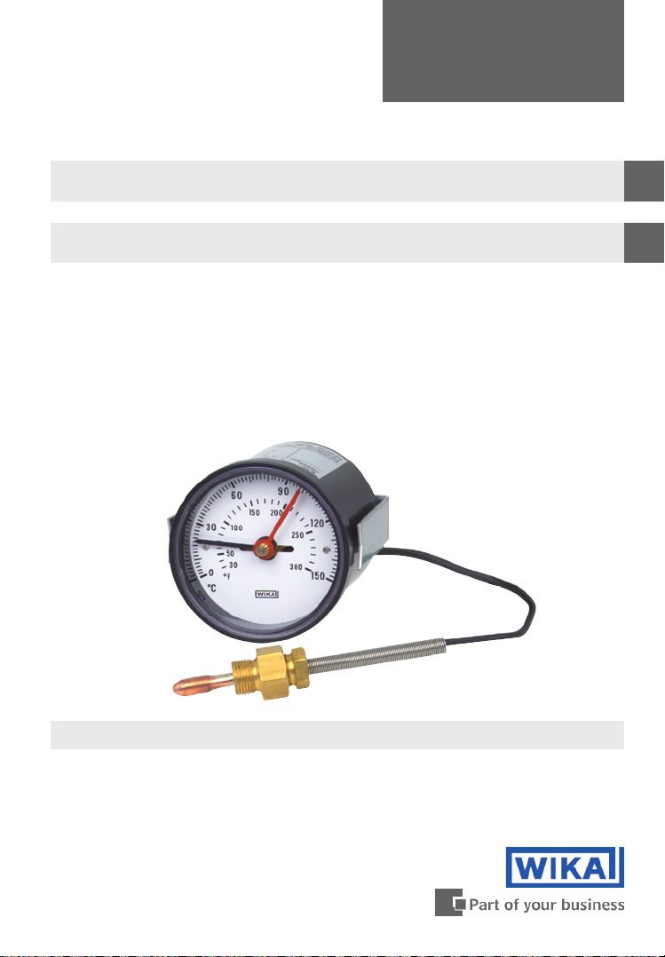
Safety Temperature Alerter Model SW15
Sicherheitstemperaturwächter Typ SW15
GB
D
Safety Temperature Alerter Model SW15
Page 2

Operating Instructions
GB
Safety Temperature Alerter Model SW15 Page 3 - 8
Betriebsanleitung
D
Sicherheitstemperaturwächter Typ SW15 Seite 9 - 17
11433116 03/2009 GB/D
2
Page 3
Contents
Contents
1. Safety instructions
GB
4
2. Application
Design and operating principle 4
3.
Technical data 5
4.
Installation, commissioning and operation 6
5.
6. Maintenance
Enclosure 1: TÜV CERT EC-type examination certificate
per directive 97/23/EG (german)
Enclosure 2: DIN CERTO DIN EN 14 597 (german)
Information
This symbol provides you with information, notes and tips.
4
7
14 - 15
16 - 17
Warning!
This Symbol warns you against actions that can cause injury to
people or damage to the instrument.
11433116 03/2009 GB/D
WIKA Operating Instructions Safety Temperature Alerter Model SW15 3
Page 4

1. Safety instructions / 2. Application / 3. Design, operating principle
1. Safety instructions
The appropriate national safety regulations (e.g. VDE 0100) must
be observed when installing, commissioning and operating
GB
Serious injuries and/or damage can occur should the appropriate
regulations not be observed.
Only appropriately qualified personnel should carry out the connection
work.
Any connection work may only be carried out once the equipment has
been isolated.
2. Application
Universally applicable safety temperature alerter for gaseous, liquid and highlyviscous process media.
3. Design and operating principle
these devices.
The fluid-filled, closed measuring system consists of a temperature sensor, a
measuring capillary and a bourdon tube. Heating the temperature sensor leads
to a volume change in the closed system and thus a change in the pressure.
This is transferred through a measuring capillary to the bourdon tube and,
through the angular motion of the pointer shaft, to the dial on the display.
When the switch point is passed, the switch disc (cam disc), fitted to the
pointer shaft, triggers the micro switch.
The fixed switching point is indicated by an additional pointer and is written on
the instrument label. The devices are equipped with capillary-break monitoring
and switch if the pressure decreases.
WIKA Operating Instructions Safety Temperature Alerter Model SW154
11433116 03/2009 GB/D
Page 5

4. Technical Data
4. Technical Data
Ingress protection
Case IP 53, terminals IP 00 (EN 60 529 / IEC 529)
Display accuracy
Max. +4 % of the measuring range at the reference temperature of 23 °C at the
case and capillary.
Scale ranges
0 °C ... 400 °C
Permissible temperatures
Case: +60 °C
Capillary:
plastic sheathed -40 °C ... +100 °C
copper braided -40 °C ... +350 °C
Scale limits
Max. 270 °
Measuring principle
Bourdon tube system
Capillary
Plastic sheathed or copper braided,
capillary of copper or stainless steel 1.4571 depending on scale range
Capillary length
Max. 5 m
Capillary outlet
Lower back
p
GB
Contact
1 Micro switch (fixed setting)
Load data
5 A, 250 V AC
There is no overcurrent protection fitted to these instruments. In order to
prevent the switches being welded through overload, a suitable protection
device should be fitted by the user.
11433116 03/2009 GB/D
WIKA Operating Instructions Safety Temperature Alerter Model SW15 5
Page 6

4. Technical data / 5. Installation, commissioning and operation
Adjustable range:
Fixed, factory pre-set to customer requirements
Standard switch differential
< 2 % of measuring range
GB
Electrical connection
0.8 x 0.63 mm terminal block or AMP plug connection
Case
Plastic (ABS), black or steel
Type of mounting
Panel mounting with clamp
Option
Panel mounting flange
5. Installation, commissioning and operation
When fitting and using the instruments, the following
fundamental requirements must be followed:
The display range of the safety temperature alerter should be chosen
so that the maximum temperature at the sensor does not exceed the
display range. Also, after the switchpoint has been exceeded, a
resultant reheating process has to be taken into account.
In operation the equipment should not be subjected to strong vibration
or impact loads.
Contamination and high ambient temperature fluctuations should be
avoided.
Any break in the capillary will destroy the instrument and result in it
switching off.
Electrical connection
The connection diagram is shown on the instrument label on the
outer rim of the case.
WIKA Operating Instructions Safety Temperature Alerter Model SW156
11433116 03/2009 GB/D
Page 7

5. Installation, commissioning and operation / 6. Maintenance
Temperature sensors for heating generation plants
Temperature sensor Sheath Operating medium
Ø
Model
SF 91 6 Brass - - x
SF 91 6 Brass SH16 Brass x
SF 91 6 Brass SH16 1.4571 x x x
SF 91 8 Brass - - x x x
SF 91 8 Brass SH16 Brass x x x
SF 91 8 Brass SH16 1.4571 x x x x x
SF 91 10 Brass - - x x x
SF 91 6 1.4571 - - x x x x x x
SF 91 6 1.4571 SH16 1.4571 x x x x x x
SF 91 8 1.4571 - - x x x x x x
SF 91 8 1.4571 SH16 1.4571 x x x x x x
SF 91 10 1.4571 - - x x x x x x
SF 91 = Design of connection 2 (WIKA data sheet TV 28.04)
6. Maintenance
The instruments require no maintenance!
We recommend that their function should be checked annually.
in mm
Material
Model
Material
Water Oil Air
p = 16 bar
p = 32 bar
T = 350 °C
p = 16 bar
T = 200 °C
T = 150 °C
p = 32 bar
T = 350 °C
unpressured
T = 350 °C
unpressured
T = 400 °C
GB
11433116 03/2009 GB/D
WIKA Operating Instructions Safety Temperature Alerter Model SW15 7
Page 8

GB
11433116 03/2009 GB/D
WIKA Operating Instructions Safety Temperature Alerter Model SW158
Page 9

Inhalt
Inhalt
1. Sicherheitshinweise
2. Anwendung
3. Aufbau und Wirkungsweise
4. Technische Daten
5. Montage, Inbetriebnahme und Betrieb
6. Wartung
Anhang 1: TÜV CERT EG-Baumusterprüfbescheinigung
nach Richtlinie 97/23/EG
Anhang 2: DIN CERTO DIN EN 14 597
Information
Dieses Zeichen gibt Ihnen Informationen, Hinweise oder Tipps.
10
10
D
10
11
12
13
14 - 15
16 - 17
Warnung!
Dieses Symbol warnt Sie vor Handlungen, die Schäden an
Personen oder am Gerät verursachen können.
11433116 03/2009 GB/D
WIKA Betriebsanleitung Sicherheitstemperaturwächter Typ SW15 9
Page 10

1. Sicherheitshinweise / 2. Anwendung / 3. Aufbau, Wirkungsweise
1. Sicherheitshinweise
Beachten Sie unbedingt bei Montage, Inbetriebnahme und
Betrieb dieser Geräte die entsprechenden nationalen Sicherheitsvorschriften (z. B. VDE 0100).
Bei Nichtbeachten der entsprechenden Vorschriften können schwere
Körperverletzungen und/oder Sachschäden auftreten.
D
Nur entsprechend qualifiziertes Personal darf die Anschlussarbeiten
durchführen.
Alle Anschlussarbeiten dürfen nur im spannungslosen Zustand durch-
geführt werden.
2. Anwendung
Universell einsetzbarer Sicherheitstemperaturwächter für gasförmige, flüssige
und hochviskose Messstoffe
3. Aufbau und Wirkungsweise
Das flüssigkeitsgefüllte, geschlossene Messsystem besteht aus einem
Temperaturfühler, Messleitung und Bourdonfeder. Die durch die Wärmebeaufschlagung am Temperaturfühler erzeugte Volumenänderung und somit auch
die Druckänderung im geschlossenen System wird durch die Messleitung zur
Bourdonfeder übertragen und über den Winkelausschlag der Zeigerwelle auf
dem Zifferblatt zur Anzeige gebracht.
Die auf der Zeigerwelle angeordnete Schaltscheibe (Kurvenscheibe) löst bei
Erreichen des Schaltpunktes den Schaltvorgang am Mikroschalter aus.
Der festeingestellte Schaltpunkt wird über einen zusätzlichen Zeiger angezeigt
und ist auf dem Typenschild vermerkt. Die Geräte sind mit einer Messleitungsbruchüberwachung ausgestattet und schalten bei Druckabfall ab.
10
WIKA Betriebsanleitung Sicherheitstemperaturwächter Typ SW15
11433116 03/2009 GB/D
Page 11

4. Technische Daten
4. Technische Daten
Schutzart
Gehäuse IP 53, Klemmen IP 00 (EN 60 529 / IEC 529)
Anzeigeabweichung
Max. +4 % des Messbereiches bei Referenztemperatur von 23 °C auf Gehäuse
und Messleitung
Anzeigebereich
0 °C ... 400 °C
Zulässige Temperaturen
Gehäuse: +60 °C
Messleitung:
kunststoffummantelt -40 °C ... +100 °C
kupferumsponnen -40 °C ... +350 °C
Skalenlänge
Max. 270 °
Messprinzip
Bourdonfedersystem
p
D
Messleitung
Kunststoffummantelt oder kupferumsponnen,
Kapillare aus Kupfer oder CrNi-Stahl 1.4571 je nach Anzeigebereich
Messleitungslänge
Max. 5 m
Messleitungsaustritt
Rückseitig exzentrisch
Kontakt
1 Mikroschalter (fest eingestellt)
Lastdaten
5 A, 250 V AC
In den Geräten sind keine Überstrom-Schutzeinrichtungen eingebaut. Um
ein Verschweißen der Schalter durch Überlast zu verhindern sind geeignete
Schutzeinrichtungen vom Anwender vorzusehen.
11433116 03/2009 GB/D
WIKA Betriebsanleitung Sicherheitstemperaturwächter Typ SW15 11
Page 12
4. Technische Daten / 5. Montage, Inbetriebnahme und Betrieb
Einstellbereich
Fest eingestellt, werkseitig nach Kundenvorgabe
Standardschaltdifferenz
< 2 % vom Messbereich
Elektrischer Anschluss
Flachstecker 0,8 x 0,63 mm oder Klemmanschluss
D
Gehäuse
Kunststoff (ABS), schwarz oder Stahl
Befestigungsart
Tafeleinbau mit Befestigungsbügel
Option
Befestigungsrand vorne
5. Montage, Inbetriebnahme und Betrieb
Für die Montage und den Betrieb der Geräte sind folgende,
grundsätzliche Anforderungen zu beachten:
Der Anzeigebereich des Temperaturwächters sollte so gewählt werden,
dass die maximal am Fühler anliegende Temperatur den Anzeigebereich
nicht überschreitet. Dabei sind auch nach überschreiten des Schaltpunktes auf-tretende Nachheizvorgänge zu beachten.
In Betrieb sollte das Gerät keinen starken Schwingungen und Stoß-
belastungen ausgesetzt sein.
Verschmutzungen und hohe Umgebungstemperaturschwankungen sind
zu vermeiden.
Ein Durchtrennen der Messleitung führt zur Zerstörung des Gerätes und
zur Abschaltung.
Elektrischer Anschluss
Die Klemmenbelegung ist auf dem Typenschild am Gehäuseumfang
angegeben.
WIKA Betriebsanleitung Sicherheitstemperaturwächter Typ SW1512
11433116 03/2009 GB/D
Page 13
5. Montage, Inbetriebnahme und Betrieb / 6. Wartung
Wärmefühler für Wärmeerzeugungsanlagen
Wärmefühler Tauchhülse Betriebsmedien
Ø
Typ
SF 91 6 Messing - - x
SF 91 6 Messing SH16 Messing x
SF 91 6 Messing SH16 1.4571 x x x
SF 91 8 Messing - - x x x
SF 91 8 Messing SH16 Messing x x x
SF 91 8 Messing SH16 1.4571 x x x x x
SF 91 10 Messing - - x x x
SF 91 6 1.4571 - - x x x x x x
SF 91 6 1.4571 SH16 1.4571 x x x x x x
SF 91 8 1.4571 - - x x x x x x
SF 91 8 1.4571 SH16 1.4571 x x x x x x
SF 91 10 1.4571 - - x x x x x x
SF 94 = Anschlussbauform 1 mit Schutzhülse SF 91 = Anschlussbauform 2 (WIKA Datenblatt TV 28.04)
6. Wartung
Die Geräte sind wartungsfrei!
Wir empfehlen eine jährliche Funktionskontrolle.
in mm
Werkstoff
Typ
Werkstoff
Wasser Öl Luft
p = 16 bar
T = 150 °C
p = 32 bar
T = 350 °C
p = 16 bar
T = 200 °C
p = 32 bar
T = 350 °C
drucklos
T = 350 °C
drucklos
T = 400 °C
D
11433116 03/2009 GB/D
WIKA Betriebsanleitung Sicherheitstemperaturwächter Typ SW15 13
Page 14

Anhang 1
D
14
11433116 03/2009 GB/D
WIKA Betriebsanleitung Sicherheitstemperaturwächter Typ SW15
Page 15

Anhang 1
D
11433116 03/2009 GB/D
WIKA Betriebsanleitung Sicherheitstemperaturwächter Typ SW15 15
Page 16

Anhang 2
D
16
11433116 03/2009 GB/D
WIKA Betriebsanleitung Sicherheitstemperaturwächter Typ SW15
Page 17

Anhang 2
D
11433116 03/2009 GB/D
WIKA Betriebsanleitung Sicherheitstemperaturwächter Typ SW15 17
Page 18

WIKA Global
Europe
Austria
WIKA Messgerätevertrieb
Ursula Wiegand
GmbH & Co. KG
1230 Vienna
Phone: (+43) 1-86 91 631
Fax: (+43) 1-86 91 634
E-mail: info@wika.at
www.wika.at
Benelux
WIKA Benelux
6101 WX Echt
Phone: (+31) 475-535 500
Fax: (+31) 475-535 446
E-mail: info@wika.nl
www.wika.nl
Bulgaria
WIKA Bulgaria EOOD
1309 Sofia
Phone: (+359) 2 82138-10
Fax: (+359) 2 82138-13
E-mail: t.antonov@wika.bg
Croatia
WIKA Croatia d.o.o.
Hrastovička 19
10250 Zagreb-Lučko
Phone: (+385) 1 6531034
Fax: (+385) 1 6531357
E-mail: info@wika.hr
Finland
WIKA Finland Oy
00210 Helsinki
Phone: (+358) 9-682 49 20
Fax: (+358) 9-682 49 270
E-mail: info@wika.fi
www.wika.fi
France
WIKA Instruments s.a.r.l.
95610 Eragny-sur-Oise
Phone: (+33) 1-34 30 84 84
Fax: (+33) 1-34 30 84 94
E-mail: info@wika.fr
www.wika.fr
18
Germany
WIKA Alexander Wiegand
GmbH & Co. KG
63911 Klingenberg
Phone: (+49) 93 72-13 20
Fax: (+49) 93 72-13 24 06
E-mail: info@wika.de
www.wika.de
Italy
WIKA Italiana SRL
20020 Arese (Milano)
Phone: (+39) 02-93 86 11
Fax: (+39) 02-93 86 174
E-mail: info@wika.it
www.wika.it
Poland
WIKA Polska S.A.
87-800 Wloclawek
Phone: (+48) 542 30 11 00
Fax: (+48) 542 30 11 01
E-mail: info@wikapolska.pl
www.wikapolska.pl
Romania
WIKA Instruments Romania
S.R.L.
Bucuresti, Sector 5
Calea Rahovei Nr. 266-268
Corp 61, Etaj 1
Phone: (+40) 21 4563138
Fax: (+40) 21 4563137
E-mail: m.anghel@wika.ro
Russia
ZAO „WIKA Mera“
127015 Moscow
Phone: (+7) 495-648 01 80
Fax: (+7) 495-648 01 81
E-mail: info@wika.ru
www.wika.ru
Serbia
WIKA Merna Tehnika d.o.o.
Sime Solaje 15
11060 Belgrade
Phone: (+381) 11 27 63 722
Fax: (+381) 11 75 36 74
E-mail: info@wika.co.yu
www.wika.co.yu
Spain
Instrumentos WIKA, S.A.
C/Josep Carner, 11-17
08205 Sabadell (Barcelona)
Phone: (+34) 902 902 577
Fax: (+34) 933 938 666
E-mail: info@wika.es
www.wika.es
Switzerland
Manometer AG
6285 Hitzkirch
Phone: (+41) 41-919 72 72
Fax: (+41) 41-919 72 73
E-mail: info@manometer.ch
www.manometer.ch
Turkey
WIKA Alexander Wiegand
GmbH & Co. KG
Türkiye (Istanbul) irtibat
bürosu
Zümrütevler Mah.
Hanimeli Cad. No. 4 Kat: 4
Maltepe - Istanbul
Phone: (+90) 216/305 46 24
Fax: (+90) 216/305 36 19
E-mail: info@wika.com.tr
www.wika.com.tr
Ukraine
WIKA Pribor GmbH
83016 Donetsk
Phone: (+38) 062 345 34 16
Fax: (+38) 062 345 34 17
E-mail: info@wika.ua
www.wika.ua
United Kingdom
WIKA Instruments Ltd
Merstham, Redhill RH13LG
Phone: (+44) (0) 1737 644 008
Fax: (+44) (0) 1737 644 403
E-mail: info@wika.co.uk
www.wika.co.uk
North America
Canada
WIKA Instruments Ltd.
Head Office
Edmonton, Alberta, T6N 1C8
Phone: (+1) 780-463 70 35
Fax: (+1) 780-462 00 17
E-mail: info@wika.ca
www.wika.ca
11433116 03/2009 GB/D
Page 19

WIKA Global
Mexico
Instrumentos WIKA Mexico
S.A. de C.V.
01210 Mexico D.F.
Phone: (+52) 555 020 53 00
Fax: (+52) 555 020 53 01
E-mail: ventas@wika.com
www.wika.com.mx
USA
WIKA Instrument Corporation
Lawrenceville, GA 30043
Phone: (+1) 770-513 82 00
Fax: (+1) 770-338 51 18
E-mail: info@wika.com
www.wika.com
South America
Argentina
WIKA Argentina S.A.
Buenos Aires
Phone: (+54) 11-4730 18 00
Fax: (+54) 11-4761 00 50
E-mail: info@wika.com.ar
www.wika.com.ar
Brazil
WIKA do Brasil Ind. e Com.
Ltda.
CEP 18560-000 Iperó - SP
Phone: (+55) 15-3459 97 00
Fax: (+55) 15-3266 16 50
E-mail: marketing@wika.
com.br
www.wika.com.br
Africa / Middle East
Egypt
WIKA Alexander Wiegand
GmbH & Co. KG
El-Serag City Towers
Tower #2, Office#67
Nasr City, Cairo
Phone: (+20) 2 2287 6219
Fax: (+20) 2 2273 3140
E-mail: ahmed.azab@wika.de
11433116 03/2009 GB/D
South Africa
WIKA Instruments (Pty.) Ltd.
Gardenview, Johannesburg
2047
Phone: (+27) 11-621 00 00
Fax: (+27) 11-621 00 59
E-mail: sales@wika.co.za
www.wika.co.za
United Arab Emirates
WIKA Middle East FZE
Jebel Ali, Dubai
Phone: (+971) 4 - 883 90 90
Fax: (+971) 4 - 883 91 98
E-mail: wikame@emirates.
net.ae
Asia
China
WIKA International Trading
(Shanghai) Co., Ltd.
200001 Shanghai
Phone: (+86) 21 - 53 85 25 72
Fax: (+86) 21 - 53 85 25 75
E-mail: info@wika.com.cn
India
WIKA Instruments India Pvt. Ltd.
Village Kesnand, Wagholi
Pune - 412 207
Phone: (+91) 20 - 66 29 32 00
Fax: (+91) 20 - 66 29 33 25
E-mail: sales@wika.co.in
www.wika.co.in
Japan
WIKA Japan K. K.
Tokyo 105-0023
Phone: (+81) 3-54 39 66 73
Fax: (+81) 3-54 39 66 74
E-mail: t-shimane@wika.co.jp
Kazakhstan
TOO WIKA Kazakhstan
050050 Almaty
Phone: (+7) 32 72 33 08 48
Fax: (+7) 32 72 78 99 05
E-mail: info@wika.kz
Korea
WIKA Korea Ltd.
Seoul 153-023
Phone: (+82) 2 - 8 69 05 05
Fax: (+82) 2 - 8 69 05 25
E-mail: info@wika.co.kr
Malaysia
WIKA Instrumentation (M)
Sdn. Bhd.
47100 Puchong, Selangor
Phone: (+03) 80 63 10 80
Fax: (+03) 80 63 10 70
E-mail: info@wika.com.my
www.wika.com.my
Singapore
WIKA Instrumentation Pte. Ltd.
569625 Singapore
Phone: (+65) 68 44 55 06
Fax: (+65) 68 44 55 07
E-mail: info@wika.com.sg
www.wika.com.sg
Taiwan
WIKA Instrumentation Taiwan
Ltd.
Pinjen, Taoyuan
Phone: (+886) 3 420 6052
Fax: (+886) 3 490 0080
E-mail: info@wika.com.tw
www.wika.com.tw
Australia
Australia
WIKA Australia Pty. Ltd.
Rydalmere, NSW 2116
Phone: (+61) 2 - 88 45 52 22
Fax: (+61) 2 - 96 84 47 67
E-mail: sales@wika.com.au
www.wika.com.au
New Zealand
Process Instruments Limited
Unit 7 / 49 Sainsbury Road
St Lukes - Auckland 1025
Phone: (+64) 9 - 847 90 20
Fax: (+64) 9 - 846 59 64
E-mail: info@wika.co.nz
www.wika.co.nz
19
Page 20

Technical alteration rights reserved.
Technische Änderungen vorbehalten.
20
WIKA Alexander Wiegand GmbH & Co. KG
Alexander-Wiegand-Strasse 30
63911 Klingenberg • Germany
Tel (+49) 9372/132-0
Fax (+49) 9372/132-406
E-Mail info@wika.de
www.wika.de
11433116.02 03/2009 GB/D
 Loading...