

Page 1
WIKA Global
Australia WIKA Australia Pty. Ltd.
Tel.: (+61) 2-88 45 52 22
E-Mail: sales@wika.com.au
Brazil WIKA do Brasil Ind. e Com. Ltda
Tel.: (+55) 15-34 599 700
E-Mail: marketing@wika.com.br
China WIKA International Trading
(Shanghai) Co., Ltd.
Tel.: (+86) 21 53 85 25 72
E-Mail: info@wika.com.cn
India WIKA Instruments India Pvt. Ltd.
Tel.: (+91) 20 66293-200
E-Mail: sales@wika.co.in
South Africa WIKA Instruments (Pty.) Ltd.
Tel.: (+27) 11/6 21 00 00
E-Mail: sales@wika.co.za
U.S.A. WIKA Instrument Corporation
Tel.: (+1) 770 / 5 13 82 00
E-Mail: info@wika.com
For WIKA's subsidiaries throughout the world please refer to...
Weitere WIKA-Niederlassungen weltweit finden Sie unter...
Vous trouvez l'adresse d'autres filiales de WIKA à l'échelle
mondiale sous...
...www.wika.de
WIKA Alexander Wiegand SE & Co. KG
Alexander-Wiegand-Straße 30
63911 Klingenberg/Germany
Tel. (+49) 9372/132-8976
Fax (+49) 9372/132-8008976
E-Mail support-tronic@wika.de
www.wika.de
2488791.07 GB/D/F 06/2010
Operating instructions
Betriebsanleitung
Mode d’emploi
SL-1
Pressure transmitter /
Druckmessumformer /
Transmetteur de pression
Page 2

Contents / Inhalt / Contenu
Contents Page 3-15 GB
1. Important details for your information
2. A quick overview for you
3. Signs, symbols and abbreviations
4. Function
5. For your safety
6. Packaging
7.
Starting, operation
8. Adjustment of zero point / span
9. Maintenance, accessories
10. Trouble shooting
11. Storage, disposal
Contenu Page 28-40 F
1. Informations inportantes
2. Aperçu rapide
3. Explication des symboles, abréviations
4. Fonction
5. Pour votre sécurité
6. Emballage
7.
Mise en service, exploitation
8. Réglage du zéro / gain
9. Entretien, accessoires
10. Elimination de perturbations
11. Stockage, mise au rebut
Inhalt Seite 16-28 D
1. Wichtiges zu Ihrer Information
2. Der schnelle Überblick für Sie
3. Zeichenerklärungen, Abkürzungen
4. Funktion
5. Zu Ihrer Sicherheit
6. Verpackung
7.
Inbetriebnahme, Betrieb
8. Einstellung Nullpunkt / Spanne
9. Wartung, Zubehör
10. Störbeseitigung
11. Lagerung, Entsorgung
2
WIKA Operating instructions/Betriebsanleitung/Mode d'emploi SL-1
Current terms and conditions apply.
Details are available on ...
Es gelten unsere aktuellen Verkaufsund Lieferbedingungen siehe unter ...
Toute commande est assujettie à nos
conditions de ventes et de fournitures
dans leur dernière version en vigueur, voir
sous ...
www.wika.de
GB D
F
1. Important details for your information / 2. A quick overview for you
1. Important details for your information
Read these operating instructions before installing and starting the pressure transmitter. Keep
the operating instructions in a place that is accessible to all users at any time.
The following installation and operating instructions have been compiled by us with great care
but it is not feasible to take all possible applications into consideration. These installation and
operation instructions should meet the needs of most pressure measurement applications. If
questions remain regarding a specific application, you can obtain further information:
With special model number, e.g. SL-10000, please note specifications in the delivery note.
If the serial number and/or the 2D code on the hexagon gets illegible (e.g. by mechanical
damage or repainting), the retraceability of the instrument is not possible any more.
WIKA pressure transmitters are carefully designed and manufactured using state-of-the-art
technology. Every component undergoes strict quality and environmental inspection before
assembly and each instrument is fully tested prior to shipment. Our environmental management system is certified to DIN EN ISO 14001.
Use of the product in accordance with the intended use SL-1:
Use the pressure transmitter to transform the pressure into an electrical signal.
Knowledge required
Install and start the pressure transmitter only if you are familiar with the relevant regulations
and directives of your country and if you have the qualification required. You have to be
acquainted with the rules and regulations on measurement and control technology and electric circuits. Depending on the operating conditions of your application you have to have the
corresponding knowledge, e.g. of aggressive media.
2. A quick overview for you
If you want to get a quick overview, read Chapters 3, 5, 7 and 11. There you will get some
short safety instructions and important information on your product and its starting. Read
these chapters in any case.
WIKA Operating instructions/Betriebsanleitung/Mode d'emploi SL-1
2488791.07 GB/D/F 06/2010
2488791.07 GB/D/F 06/2010
GB
Via our Internet address www.wika.de / www.wika.com
The product data sheet is designated as PE 81.36
Contact WIKA for additional technical support (+49) 9372 / 132-8976
3
Page 3

3. Signs, symbols and abbreviations / 4. Function / 5. For your safety
GB
3. Signs, symbols and abbreviations
Potential danger of life or of
!
Warning
Caution
2-wire Two connection lines are intended for the voltage supply.
The supply current is the measurement signal.
3-wire Two connection lines are intended for the voltage supply.
One connection line is intended for the measurement signal.
severe injuries.
Potential danger of burns
due to hot surfaces.
Notice, important information, malfunction.
The product complies with
the applicable European
directives.
4. Function
The pressure prevailing within the application is transformed into a standardised electrical
signal through the deflection of the diaphragm, which acts on the sensor element with the
power supply fed to the transmitter. This electric signal changes in proportion to the pressure
and can be evaluated correspondingly.
5. For your safety
Select the appropriate pressure transmitter with regard to scale range,
!
Warning
Please note that the pressure measuring instrument is suitable for clean, dry,
non-aggressive gases only.
Open pressure connections only after the system is without pressure!
performance and specific measurement conditions prior to installing and
starting the instrument.
Observe the relevant national regulations and observe the applicable stan-
dards and directives for special applications.
If you do not observe the appropriate regulations, serious injuries and/
or damage can occur!
5. For your safety / 6. Packaging / 7. Starting, operation
Please make sure that the pressure transmitter is only used within the over-
!
Warning
Ensure that the pressure transmitter is only operated in accordance with the provisions i.e.
as described in the following instructions.
Do not interfere with or change the pressure transmitter in any other way than described in
these operating instructions.
Remove the pressure transmitter from service and mark it to prevent it from being used
again accidentally, if it becomes damaged or unsafe for operation.
Take precautions with regard to remaining media in removed pressure transmitter. Remai-
ning media in the pressure port may be hazardous or toxic!
Have repairs performed by the manufacturer only.
load threshold limit all the time!
Observe the ambient and working conditions outlined in section 7 „Technical
data”.
6. Packaging
Has everything been supplied?
Check the scope of supply:
Completely assembled pressure transmitters
Inspect the pressure transmitter for possible damage during transportation. Should
there be any obvious damage, inform the transport company and WIKA without delay.
Keep the packaging, as it offers optimal protection during transportation (e.g. chan-
ging installation location, shipment for repair).
Ensure that the pressure connection thread and the connection contacts will not be
damaged.
7. Starting, operation
Required tools: wrench (flats 27), screw driver
GB
4
WIKA Operating instructions/Betriebsanleitung/Mode d'emploi SL-1
WIKA Operating instructions/Betriebsanleitung/Mode d'emploi SL-1
2488791.07 GB/D/F 06/2010
2488791.07 GB/D/F 06/2010
5
Page 4

7. Starting, operation
GB
Diaphragm test for your safety
It is necessary that before starting the pressure transmitter you test the diaphragm, as this is
a safety-relevant component.
Use the pressure transmitter only if the diaphragm is undamaged.
!
Warning
Use the pressure transmitter only if it is in a faultless condition as far as the
safety-relevant features are concerned.
7. Starting, operation
Screw in or unscrew the instrument only via the flats using a suitable tool and the
prescribed torque. The appropriate torque depends on the dimension of the pressure
connection and on the sealing element used (form/material). Do not use the case as
working surface for screwing in or unscrewing the instrument.
When screwing the transmitter in, ensure that the threads are not jammed.
For tapped holes and welding sockets please see Technical Information IN 00.14 for
download at www.wika.de
GB
Mechanical connection
max.
50 Nm
Sealing
If there is no serial number on the product label, the number on the hexagon will apply.
Product label (example)
Signal
Power Supply
Serial No.
S #
Product No.
P #
PIN assignment
Coded manufacture date
You have to provide for a sealing element; exceptions are instruments with self-
sealing threads (e.g. NPT thread).
Please refer to our data sheet “Pressure gauge sealing washers AC 09.08” in WIKA’s
product catalog Pressure and Temperature Measurement or our website
www.wika.de for details about sealing washers.
When mounting the instrument, ensure that the sealing faces of the instrument and
the measuring point are clean and undamaged.
6
WIKA Operating instructions/Betriebsanleitung/Mode d'emploi SL-1
Electrical connection
Connect the instrument to earth via the pressure connection.
This equipment of protection class 3 is designed for connection to safety low voltages
that are separated from the mains voltage or from a voltage greater than AC 50 V or
DC 120 V. It is preferred to connect it to SELV or PELV electric circuits; alternatively, a
safety measure from HD 60346-4-41 (DIN VDE 0100-410) is recommended.
Alternative for North America: The connection may also be made to „Class 2 Circuits“
or „Class 2 Power Units“ according to CEC (Canadian Electrical Code) or NEC (Nati-
onal Electrical Code).
Operate the pressure transmitter with a shielded cable and earth the shield at least
on one side of the cable, if the cable is longer than 30 m or if it is run outside of the
building.
Ingress protection per IEC 60529 (The ingress protection classes specified only apply
while the pressure transmitter is connected with female connectors that provide the
corresponding ingress protection).
Ensure that the cable diameter you select fits to the cable gland of the connector.
Ensure that the cable gland of the mounted connector is positioned correctly and
that the sealings are available and undamaged. Tighten the threaded connection and
check the correct position of the sealings in order to ensure the ingress protection.
Please make sure that the ends of cables with flying leads do not allow any ingress of
moisture.
WIKA Operating instructions/Betriebsanleitung/Mode d'emploi SL-1
2488791.07 GB/D/F 06/2010
2488791.07 GB/D/F 06/2010
7
Page 5

7. Starting, operation
Power supply
Load (e.g. display)
UB+/Sig+ Positive supply / measurement connection
OV/Sig- Negative supply / measurement connection
L-Connector,
DIN EN 175301-803, Form A
for conducter cross section up
to max. 1.5 mm², conducter
outer diameter 6 to 8 mm
IP 65
Circular connector
M 12x1,
IP 67
Flying leads with 1.5 m of cable,
conducter cross section up
to max. 0.5 mm ², AWG 20
with end splices, conducter outer
diameter 6.8 mm;
cable screen: grey
IP 67
8
WIKA Operating instructions/Betriebsanleitung/Mode d'emploi SL-1
brown
green
GB
7. Starting, operation
GB
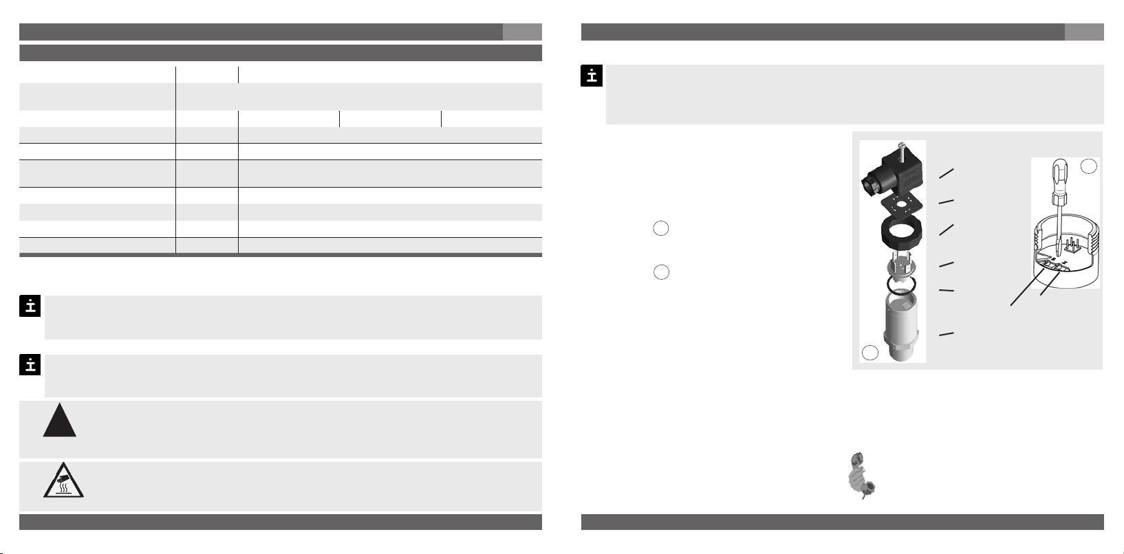
Assembly of L-connector DIN EN 175301-803
(D) Mounting hole
(2)
(3)
3-wire2-wire
1. Loosen the screw (1).
2. Loosen the cable gland (2).
(4)
(1)
(5)
Female
connector
(6)
Sealing
3. Pull the angle housing (5), with the
terminal block (6) inside, away from the
instrument.
4. Using the head of a small screwdriver in
Clamping nut,
Male connector,
Case with
pressure connection
the mounting hole (D), lever the terminal
block (6) out of the angle housing (5).
In order not to damage the sealing of the angle housing, do not try to push the terminal
block (6) out using the screw hole (1) or the cable gland (2).
5. Ensure that the conductor outer diameter you select is matched to the angle housing’s
cable gland. Slide the cable through the cable gland nut (2), washer (3), gland seal (4) and
angle housing (5).
6. Connect the flying leads to the screw terminals on the terminal block (6) in accordance
with the pin-assignment drawing.
brown
7. Press the terminal block (6) back into the angle housing (5).
8. Tighten the cable gland (2) around the cable. Make sure that the sealing isn’t damaged
and that the cable gland and seals are assembled correctly in order to ensure ingress
white
green
protection.
9. Place the flat, square gasket over the connection pins on the top of the instrument
housing.
10. Slide the terminal block (6) onto the connection pins.
11. Secure the angle housing (5) and terminal block (6) to the instrument with the screw (1).
WIKA Operating instructions/Betriebsanleitung/Mode d'emploi SL-1
2488791.07 GB/D/F 06/2010
2488791.07 GB/D/F 06/2010
9
Page 6
7. Starting, operation
Specifications Model SL-1
Pressure ranges mbar 25 40 60
Over pressure safety mbar 500 500 500
Pressure ranges mbar 1000 1000 1000
Type of Pressure Relative pressure
Materials
Wetted parts Stainless steel, silicon, aluminium, gold, silicone
Case Stainless steel
Power supply U
Signal output and R
maximum ohmic load R
Adjustability zero/span %
Insulation voltage DC 500 V *
Accuracy **
Non-linearity % of span
Non-repeatability % of span
1-year stability % of span
Permissible temperature of
Medium -30 ... +80 °C -22 ... +176 °F
Ambience -20 ... +80 °C -4 ... +176 °F
Storage -40 ... +80 °C -40 ... +176 °F
B DC 10 ... 30 V (DC 14 … 30 V with signal output 0 … 10 V)
A in Ohm 4 … 20 mA, 2-wire RA ≤ (UB – 10 V) / 0.02 A
A {0 … 5 V, 3-wire} RA > 5000
{0 … 10 V, 3-wire} R
{other signal output on request}
A > 10000
± 5 using potentiometers inside the instrument
)
*) Use NEC Class 02 power supply (low voltage and low current max. 100 VA even
)
under fault conditions)
% of span
)
Including non-linearity, hysteresis, zero point and full scale error (corresponds to
**
error of measurement per IEC 61298-2).
Adjusted in vertical mounting position with lower pressure connection.
0.5
≤
0.2 (BFSL) according to IEC 61298-2
≤
≤
0.1
≤
0.3 (at reference conditions)
GB
7. Starting, operation
Specifications Model SL-1
Rated temperature range 0 ... +80 °C 32 ... +176 °F
Temperature coefficients within
rated temperature range
Mean TC of zero % of span 25 mbar: 0.5 / 10 K 40 mbar: 0.4 / 10 K 60 mbar: 0.3 / 10 K
Mean TC of range % of span
RoHS-conformity Yes
CE-conformitiy
Wiring protection
Short-circuit proofness Sig+ towards 0V/Sig-
Reverse polarity protection UB+ towards 0V/Sig-
Weight kg Approx. 0.3
{ } Items in curved brackets are optional extras for additional price.
≤
0.3 / 10 K
2004/108/EC, EN 61 326 Emission (Group 1, Class B) and Immunity
(industrial locations)
When designing your plant, take into account that the stated values (e.g.burst pressure,
over pressure safety) apply depending on the material, thread and sealing element used.
Functional test
The output signal must be proportional to the pressure. If not, this might point to a
damage of the diaphragm. In that case refer to chapter 10 „Troubleshooting“.
Open pressure connections only after the system is without pressure!
!
Warning
Observe the ambient and working conditions outlined in section 7 „Technical
data".
Please make sure that the pressure transmitter is only used within the over-
load threshold limit at all times!
When touching the pressure transmitter, keep in mind that the surfaces of
the instrument components might get hot during operation.
Caution
GB
10
WIKA Operating instructions/Betriebsanleitung/Mode d'emploi SL-1
WIKA Operating instructions/Betriebsanleitung/Mode d'emploi SL-1
2488791.07 GB/D/F 06/2010
2488791.07 GB/D/F 06/2010
11
Page 7

8. Adjustment of zero point / span
GB
9. Maintenance, accessories / 10. Trouble shooting
GB
8. Adjustment of zero point / span (only for pressure transmitter with
clamping nut)
We do not recommend to adjust the span potentiometer. It is used for adjustment ex
factory and should not be adjusted by you unless you have adequate calibration equipment at your disposal (at least three times more accurate than the instrument being
tested).
Make sure wires are not cut or pinche
during disassembly and reassembly of
the connector.
Remove the female connector. Open
the pressure transmitter by detaching
the clamping nut (see Fig. A ). Carefully
remove the male connector from the
case.
Adjust the zero point (Z) (see Fig. B ) by
generating the lower limit of the pressure
range.
Adjust the span (S) by generating the
higher limit of the pressure range.
Check the zero point.
If the zero point is incorrect, repeat
procedure as required.
Reassemble the instrument carefully.
Make sure all sealings and o-rings are
not damaged and correctly installed to
assure the rated moisture ingress protec-
tion.
Recommended recalibration cycle: 1 year
A
For further information (+49) 9372/132-8976
Female
connector
Sealing
Clamping
nut
Male
connector
Sealing
Case with
pressure
connection
S = Span
Z = Zero
B
9. Maintenance, accessories
WIKA pressure transmitters require no maintenance.
Have repairs performed by the manufacturer only.
Accessories
For details about the accessories (e. g. connectors), please refer to WIKA‘s price list, WIKA‘s
product catalog on CD or or contact our sales department.
10. Trouble shooting
Open pressure connections only after the system is without pressure!
!
Warning
Take precautions with regard to remaining media in removed pressure trans-
!
Warning
Do not insert any pointed or hard objects into the pressure port for cleaning to prevent
damage to the diaphragm of the pressure connection.
Do not clean the pressure port with liquids or compressed air!
mitters. Remaining media in the pressure port may be hazardous or
toxic!
Remove the pressure transmitter from service and mark it to prevent it from
being used again accidentally, if it becomes damaged or unsafe for operation.
Have repairs performed by the manufacturer only.
12
WIKA Operating instructions/Betriebsanleitung/Mode d'emploi SL-1
WIKA Operating instructions/Betriebsanleitung/Mode d'emploi SL-1
2488791.07 GB/D/F 06/2010
2488791.07 GB/D/F 06/2010
13
Page 8

10. Trouble shooting
GB
10. Trouble shooting / 11. Storage, disposal
GB
Please verify in advance if pressure is being applied (valves/ ball valve etc. open) and if the
right voltage supply and the right type of wiring (2-wire/ 3-wire) has been chosen?
Failure Possible cause Procedure
No output signal
No/False output signal
Abnormal output signal Span incorrectly adjusted Use appropriate reference
Output signal unchanged after change
in pressure
Signal span too small Power supply too high/too low
Signal span drops off Moisture present (e.g. at the cable tail) Install the cable correctly
Signal span erratic
In case of unjustified reclamation we charge the reclamation handling expenses.
*) Make sure that after the setting the unit is working properly. In case the error continues to exist send in the instrument for reparation (or
replace the unit).
No/incorrect voltage supply or current
spike
Cable break Check connections and cable
Incorrectly wired (e.g. Connected as
2-wire instead of 3-wire system)
Zero point set wrongly
Mechanical overload through overpressure
Wrong supply voltage or current spike Replace instrument
Electromagnetic interference source in
the vicinity, e.g. inverter drive
Instrument not grounded Ground instrument
Strong fluctuations in the power supply
Adjust the voltage supply to correspond
with the Operating Instructions *)
Follow pin assignment (see Instrument
Label / Operating Instructions)
Use correct calibration equipment (at
least 3x the accuracy of the quoted
accuracy)
Replace instrument; if failure reoccurs,
consult the manufacturer *)
Correct the power supply in line with
the Operating Instructions
Shield the device; shield the cables;
remove the interference source.
Stabilise the power supply; smooth it
(i.e.; remove interferences)
If the problem persists, contact our sales department.
USA, Canada
If the problem continues, contact WIKA or an authorized agent for assistance. If the pressure transmitter must be returned obtain an RMA (return material authorization) number and
shipping instructions from the place of purchase. Be sure to include detailed information about
the problem. Pressure transmitters received by WIKA without a valid RMA number will not be
accepted.
Process material certificate (Contamination declaration for returned goods)
Clean dismounted instruments before returning them in order to protect our employees and
the environment from any hazard caused by adherent remaining media.
Service of instruments can only take place safely when a Product Return Form has been
submitted and fully filled-in. This Return Form contains information on all materials with which
the instrument has come into contact, either through installation, test purposes, or cleaning.
You can find the Product Return Form on our internet site (www.wika.de / www.wika.com).
11. Storage, disposal
When storing or disposing of the pressure transmitter, take precautions with
!
Warning
Disposal
Dispose of instrument components and packaging materials in accordance with the
respective waste treatment and disposal regulations of the region or country to which
the instrument is supplied.
regard to remaining media in removed pressure transmitters. We recommend cleaning the transmitter properly and carefully. Remaining media in
the pressure port may be hazardous or toxic!
14
WIKA Operating instructions/Betriebsanleitung/Mode d'emploi SL-1
WIKA reserves the right to alter these technical specifications.
WIKA Operating instructions/Betriebsanleitung/Mode d'emploi SL-1
2488791.07 GB/D/F 06/2010
2488791.07 GB/D/F 06/2010
15
Page 9

1. Wichiges zu Ihrer Information/ 2. Schneller Überblick
D
1. Wichtiges zu Ihrer Information
Lesen Sie diese Betriebsanleitung vor Montage und Inbetriebnahme des Druckmessgerätes.
Bewahren Sie die Betriebsanleitung an einem für alle Benutzer jederzeit zugänglichen Ort auf.
Die nachfolgenden Einbau- und Betriebshinweise haben wir mit Sorgfalt zusammengestellt.
Es ist jedoch nicht möglich, alle erdenklichen Anwendungsfälle zu berücksichtigen. Sollten Sie
Hinweise für Ihre spezielle Aufgabenstellung vermissen, können Sie hier weitere Informationen
finden:
Über unsere Internet-Adresse www.wika.de / www.wika.com
Die Bezeichnung des zugehörigen Datenblattes ist PE 81.36
Anwendungsberater: (+49) 9372/132-8976
Bei Sondertypennummer, z.B. SL-10000 beachten Sie die Spezifikationen gemäß Lieferschein.
Wird die Seriennummer und/oder der 2D-Code auf dem Sechskant unleserlich (z. B. durch
mechanische Beschädigung oder Übermalen), ist eine Rückverfolgbarkeit nicht mehr möglich.
Die in der Betriebsanleitung beschriebenen WIKA-Druckmessgeräte werden nach den
neuesten Erkenntnissen konstruiert und gefertigt. Alle Komponenten unterliegen während der
Fertigung strengen Qualitäts- und Umweltkriterien. Unser Umweltmanagementsystem ist nach
DIN EN ISO 14001 zertifiziert.
3. Zeichenerklärungen, Abkürzungen / 4. Funktion / 5. Zu Ihrer Sicherheit
D
3. Zeichenerklärungen, Abkürzungen
Mögliche Gefahr für Ihr
!
Warnung
Vorsicht
2-Leiter Zwei Anschlussleitungen dienen zur Spannungsversorgung.
Der Speisestrom ist das Mess-Signal.
3-Leiter Zwei Anschlussleitungen dienen zur Spannungsversorgung.
Eine Anschlussleitung dient für das Mess-Signal.
Leben oder schwerer
Verletzungen.
Mögliche Gefahr von
Verbrennungen durch
heisse Oberflächen.
Hinweis, wichtige Information, Funktionsstörung.
Das Produkt stimmt mit den
zutreffenden europäischen
Richtlinien überein.
4. Funktion
Mittels Sensorelement und unter Zuführung von Hilfsenergie wird über die Verformung einer
Membran der anstehende Druck in Ihrer Anwendung in ein verstärktes standardisiertes elektrisches Signal umgewandelt. Dieses elektrische Signal verändert sich proportional zum Druck
und kann entsprechend ausgewertet werden.
Bestimmungsgemäße Produktverwendung SL-1:
Verwenden Sie den Druckmessumformer, um Druck in ein elektrisches Signal zu wandeln.
Ihre erforderlichen Kenntnisse
Montieren und nehmen Sie das Druckmessgerät nur in Betrieb, wenn Sie mit den zutreffenden
landesspezifischen Richtlinien vertraut sind und die entsprechende Qualifikation besitzen. Sie
müssen mit den Kenntnissen von Mess- und Regeltechnik sowie elektrischen Stromkreisen
vertraut sein. Je nach Einsatzbedingung müssen Sie über entsprechendes Wissen verfügen, z.
B. über agressive Medien.
2. Der schnelle Überblick für Sie
Wollen Sie sich einen schnellen Überblick verschaffen, lesen Sie Kapitel 3, 5, 7 und 11. Dort
erhalten Sie kurze Hinweise zu Ihrer Sicherheit und wichtige Informationen über Ihr Produkt
und zur Inbetriebnahme. Lesen Sie diese unbedingt.
16
WIKA Operating instructions/Betriebsanleitung/Mode d'emploi SL-1
5. Zu Ihrer Sicherheit
Wählen Sie das richtige Druckmessgerät hinsichtlich Messbereich, Ausfüh-
!
Warnung
Bitte beachten Sie, dass das Druckmessgerät nur für saubere, trockene, nicht
aggressive Gase geeignet ist.
Öffnen Sie Anschlüsse nur im drucklosen Zustand!
Betreiben Sie das Druckmessgerät immer innerhalb des Überlastgrenzbereiches!
Beachten Sie die Betriebsparameter gemäß Punkt 7 „Technische Daten“.
WIKA Operating instructions/Betriebsanleitung/Mode d'emploi SL-1
2488791.07 GB/D/F 06/2010
2488791.07 GB/D/F 06/2010
rung und spezifischen Messbedingungen vor Montage oder Inbetriebnahme.
Halten Sie die entsprechenden landesspezifischen Vorschriften ein und
beachten Sie bei speziellen Anwendungen die geltenden Normen und Richtlinien.
Wenn Sie die entsprechenden Vorschriften nicht beachten, können
schwere Körperverletzungen und Sachschäden entstehen!
17
Page 10

5. Zu Ihrer Sicherheit / 6. Verpackung / 7. Inbetriebnahme, Betrieb
Stellen Sie sicher, dass das Druckmessgerät nur bestimmungsgemäß -also
!
Warnung
Setzen Sie das Druckmessgerät außer Betrieb und schützen Sie es gegen versehentliche
Inbetriebnahme, wenn Sie Störungen nicht beseitigen können.
Ergreifen Sie Vorsichtsmaßnahmen für Messstoffreste in ausgebauten Druckmessgeräten.
Messstoffreste können zur Gefährdung von Menschen, Umwelt und Einrichtung führen!
Lassen Sie Reparaturen nur vom Hersteller durchführen
wie in der folgenden Anleitung beschrieben- betrieben wird.
Unterlassen Sie unzulässige Eingriffe und Änderungen am Druckmessgerät,
welche nicht in dieser Betriebsanleitung beschrieben sind.
6. Verpackung
Wurde alles geliefert?
Überprüfen Sie den Lieferumfang: Komplett montierte Druckmessgeräte
Untersuchen Sie das Druckmessgerät auf eventuell entstandene Transportschäden.
Sind offensichtlich Schäden vorhanden, teilen Sie dies dem Transportunternehmen
und WIKA unverzüglich mit.
Bewahren Sie die Verpackung auf, denn diese bietet bei einem Transport einen opti-
malen Schutz (z. B. wechselnder Einbauort, Reparatursendung).
Achten sie darauf, dass das Druckanschluss-Gewinde und die Anschlusskontakte
nicht beschädigt werden.
7. Inbetriebnahme, Betrieb
Membran-Prüfung zu Ihrer Sicherheit
Benötigtes Werkzeug: Maulschlüssel SW 27, Schraubendreher
D
7. Inbetriebnahme, Betrieb
Es ist erforderlich, dass Sie vor Inbetriebnahme des Druckmessgerätes die Membran prüfen,
denn sie ist ein sicherheitsrelevantes Teil.
Setzen Sie das Druckmessgerät nur ein, wenn die Membran unbeschädigt
!
Warnung
Montage mechanischer Anschluss
Befindet sich keine Seriennummer auf dem Typenschild, so gilt die Nummer auf dem Sechskant.
Sie müssen eine Dichtung vorsehen; Ausnahme sind Geräte mit selbstdichtendem
Gewinde (z. B. NPT-Gewinde).
Hinweise zu Dichtungen entnehmen Sie bitte unserer Information “Zubehör Dich-
tungen AC 09.08” im Gesamtkatalog Druck- und Temperaturmesstechnik oder
unserer Internet-Seite unter www.wika.de.
Achten Sie bei der Montage auf saubere und unbeschädigte Dichtflächen am Gerät
und Messstelle.
ist.
Setzen Sie das Druckmessgerät nur in sicherheitstechnisch einwandfreiem-
Zustand ein.
Typenschild (Beispiel)
max.
50 Nm
Dichtung
Signal
Spannungsversorgung
Fabrik Nr.
S #
P #
Erzeugnis-Nr.
Anschlussbelegung
Codiertes Herstelldatum
D
18
WIKA Operating instructions/Betriebsanleitung/Mode d'emploi SL-1
WIKA Operating instructions/Betriebsanleitung/Mode d'emploi SL-1
2488791.07 GB/D/F 06/2010
2488791.07 GB/D/F 06/2010
19
Page 11

7. Inbetriebnahme, Betrieb
Schrauben Sie das Gerät nur über die Schlüsselflächen mit einem geeigneten Werk-
zeug und dem vorgeschriebenen Drehmoment ein bzw. aus. Das richtige Drehmoment ist abhängig von der Dimension des Druckanschlusses sowie der verwendeten
Dichtung (Form/Werkstoff). Verwenden Sie zum Ein- bzw. Ausschrauben nicht das
Gehäuse als Angriffsfläche.
Beachten Sie beim Einschrauben, dass die Gewindegänge nicht verkantet werden.
Angaben zu Einschraublöchern und Einschweißstutzen entnehmen Sie bitte unserer
Technischen Information IN 00.14 unter www.wika.de
Montage elektrischer Anschluss
Erden Sie das Gerät über den Druckanschluss.
Dies ist ein Betriebsmittel der Schutzklasse 3 zum Anschluss an Kleinspannungen, die
von der Netzspannung oder Spannung größer AC 50 V bzw. DC 120 V getrennt sind.
Zu bevorzugen ist ein Anschluss an SELV- oder PELV-Stromkreise; alternativ ist eine
Schutzmaßnahme aus HD 60346-4-41 (DIN VDE 0100-410) zu empfehlen.
Alternativ für Nordamerika: Der Anschluss kann auch an „Class 2 Circuits“ oder
„Class 2 Power Units“ gemäß CEC (Canadian Electrical Code) oder NEC (National
Electrical Code) erfolgen.
Betreiben Sie den Druckmessumformer mit geschirmter Leitung und erden Sie den
Schirm auf mindestens einer Leitungsseite, wenn die Leitungen länger als 30 m sind
oder das Gebäude verlassen.
Schutzart IP nach IEC 60 529 (Die angegebenen Schutzarten gelten nur im gesteckten
Zustand mit Leitungsteckern (Buchsen) entsprechender Schutzart).
Wählen Sie den Kabeldurchmesser passend zur Kabeldurchführung des Steckers.
Achten Sie darauf, dass die Kabelverschraubung des montierten Steckers korrekt
sitzt und dass die Dichtungen vorhanden und nicht beschädigt sind. Ziehen Sie die
Verschraubung fest und überprüfen Sie den korrekten Sitz der Dichtungen, um die
Schutzart zu gewährleisten.
Stellen Sie bei Kabelausgängen sicher, dass am Ende des Kabels keine Feuchtigkeit
eintritt.
20
WIKA Operating instructions/Betriebsanleitung/Mode d'emploi SL-1
D
UB+/Sig+ Positiver Versorgungs- / Messanschluss
OV/Sig- Negativer Versorgungs- / Messanschluss
2488791.07 GB/D/F 06/2010
2488791.07 GB/D/F 06/2010
7. Inbetriebnahme, Betrieb
Spannungsversorgung
Winkelsteckverbinder
DIN 175301-803, Form A
für Leitungsquerschnitt bis
max. 1,5 mm ², Leitungsaußendurchmesser 6 - 8 mm
IP 65
Rundsteckverbinder
M 12x1,
IP 67
Kabelausgang mit 1,5 m Länge,
Leitungsquerschnitt 0,5 mm²,
AWG 20 mit Aderendhülsen,
Leitungsaußendurchmesser
6,8 mm;
Kabelschirm: grau
IP 67
WIKA Operating instructions/Betriebsanleitung/Mode d'emploi SL-1
Verbraucher
braun
grün
D
3-Leiter2-Leiter
braun
weiß
grün
21
Page 12

7. Inbetriebnahme, Betrieb
D
Montage des Winkelsteckverbinder nach DIN EN 175301-803
(D) Montageöffnung
1. Lösen Sie die Schraube (1).
2. Lösen Sie die Kabelverschraubung (2).
(2)
(3)
(4)
(1)
(5)
Leitungsstecker
(Buchse)
(6)
Dichtung
3. Ziehen Sie Winkelgehäuse (5)mit Klemm block (6) vom Gerät ab.
4. Hebeln Sie mit dem Schraubendreher in
die Montageöffnung (D), so dass Sie den
Griffring,
Gerätestecker(Stift),
Gehäuse mit
Druckanschluss
Klemmblock (6) aus dem Winkelgehäuse (5)
herausdrücken. Drücken Sie nicht den
Klemmblock (6) durch die Schraubenöffnung (1) bzw. Kabelverschraubung (2) heraus,
sonst beschädigen Sie die Dichtungen des Winkelgehäuses.
5. Wählen Sie den Leitungsaußendurchmesser passend zur Kabeldurchführung des Winkel
gehäuses. Schieben Sie das Kabel durch Kabelverschraubung (2), Ring (3), Dichtung (4)
und Winkelgehäuse (5).
6. Schließen Sie die Kabelenden entsprechend der Belegungszeichnung in den Anschluß
klemmen des Klemmblocks (6) an.
7. Drücken Sie das Winkelgehäuse (5) auf den Klemmblock (6).
8. Verschrauben Sie das Kabel mit der Kabelverschraubung (2). Achten Sie darauf, dass die
Dichtungen unbeschädigt sind und Kabelverschraubung und Dichtungen korrekt sitzen,
um die Schutzart zu gewährleisten.
9. Legen Sie die quadratische Flachdichtung über die Anschlußpins im Gehäuse.
10. Schieben Sie den Klemmblock (6) auf die Anschlußpins im Gehäuse.
11. Verschrauben Sie mit der Schraube (1) das Winkelgehäuse (5) mit dem Klemmblock (6) im
Gerät.
22
WIKA Operating instructions/Betriebsanleitung/Mode d'emploi SL-1
7. Inbetriebnahme, Betrieb
Technische Daten Typ SL-1
Messbereich mbar 25 40 60
Überlastgrenze mbar 500 500 500
Berstdruck mbar 1000 1000 1000
Relativdruck
Werkstoff
Messstoffberührte Teile CrNi-Stahl, Silizium, Aluminium, Gold, Silikon
Gehäuse CrNi-Stahl
Hilfsenergie U
Ausgangssignal und zulässige R
max. ohmsche Bürde R
Einstellbarkeit Nullpunkt/Spanne %
Isolationsspannung DC 500 V *
Genauigkeit **
Nichtlinearität % d. Spanne
Nichtwiederholbarkeit % d. Spanne
Stabilität pro Jahr % d. Spanne
Zulässige Temperaturbereiche
Messstoff °C -30 … +80
Umgebung °C -20 ... +80
Lagerung °C -40 ... +80
WIKA Operating instructions/Betriebsanleitung/Mode d'emploi SL-1
2488791.07 GB/D/F 06/2010
2488791.07 GB/D/F 06/2010
B DC 10 ... 30 V (DC 14 … 30 V bei Ausgang 0 … 10 V)
A in Ohm 4 … 20 mA, 2-Leiter RA ≤ (UB – 10 V) / 0,02 A
A {0 … 5 V, 3-Leiter} RA > 5.000
{0 … 10 V, 3-Leiter} R
{andere Ausgangssignale auf Anfrage}
± 5 durch Potentiometer im Gerät
)
*) NEC Class 02 Spannungsversorgung (Leistungsbegrenzung max. 100 VA
)
auch im Fehlerzustand)
% d. Spanne
)
Einschließlich Nichtlinearität, Hysterese, Nullpunkt- und Endwertabweichung
**
(entspricht Messabweichung nach IEC 61298-2).
Kalibriert bei senkrechter Einbaulage Druckanschluss nach unten.
0,5
≤
0,2 (BFSL) nach IEC 61298-2
≤
≤
0,1
≤
0,3 (bei Referenzbedingungen)
D
A > 10.000
23
Page 13
7. Inbetriebnahme, Betrieb
Technische Daten Typ SL-1
Nenntemperaturbereich °C 0 ... +80
Temperaturkoeffizienten im
Nenntemperaturbereich
Mittlerer TK des Nullpunktes % d. Spanne 25 mbar: 0,5 / 10 K 40 mbar: 0,4 / 10 K 60 mbar: 0,3 / 10 K
Mittlerer TK der Spanne % d. Spanne
RoHS-Konformität Ja
CE-Konformität
Elektrische Schutzarten
Kurzschlussfestigkeit Sig+ gegen 0V/Sig-
Verpolschutz UB+ gegen 0V/Sig-
Masse kg Ca. 0,3
{ } Angaben in geschweiften Klammern beschreiben gegen Mehrpreis lieferbare Sonderheiten.
≤
0,3 / 10 K
2004/108/EG, EN 61326 Emission (Gruppe 1, Klasse B) und
Störfestigkeit (industrieller Bereich)
Beachten Sie bei der Auslegung Ihrer Anlage, dass die angegebenen Werte (z. B.
Berstdruck, Überlastgrenze) in Abhängigkeit vom verwendeten Material, Gewinde und
Dichtung gelten.
Funktionsprüfung
Das Ausgangssignal muss sich dem anstehenden Druck proportional verhalten. Wenn
dies nicht so ist, kann das ein Hinweis auf eine Beschädigung der Membran sein. Lesen
Sie in diesem Fall in Kapitel 10 „Störbeseitigung“ nach.
Öffnen Sie Anschlüsse nur im drucklosen Zustand!
!
Warnung
Beachten Sie die Betriebsparameter gemäß Punkt 7„Technische Daten“.
Betreiben Sie das Druckmessgerät immer innerhalb des Überlastgrenzbe-
reichs!
Beachten Sie beim Berühren des Druckmessgerätes, dass die Oberflächen
der Gerätekomponenten während des Betriebes heiß werden können.
Vorsicht
24
WIKA Operating instructions/Betriebsanleitung/Mode d'emploi SL-1
D
8. Einstellung Nullpunkt / Spanne (nur bei Geräten mit Griffring)
Empfohlener Nachkalibrier-Zyklus: 1 Jahr
2488791.07 GB/D/F 06/2010
2488791.07 GB/D/F 06/2010
8. Einstellung Nullpunkt / Spanne
Wir empfehlen Ihnen, das Spannepotentiometer nicht zu verstellen. Es dient zur werkseitigen Justage und sollte nur von Ihnen verstellt werden, wenn Sie über die ausreichende Kalibrierausstattung (mindestens 3x genauer als die angegebene Genauigkeit)
verfügen.
Achten Sie bei der Steckerdemontage /-
montage darauf, dass keine Litzen
abgerissen bzw. eingequetscht werden.
Ziehen Sie den Leitungstecker(Buchse)
ab. Öffnen Sie das Druckmessgerät,
Leitungsstecker
(Buchse)
Dichtung
indem Sie den Griffring lösen (siehe
Abbildung A ). Ziehen Sie vorsichtig den
Gerätestecker(Stift) aus dem Gehäuse.
Stellen Sie den Nullpunkt (Z) ein (siehe
Abbildung B ), indem Sie den Druckan-
fangswert anfahren.
Stellen Sie die Spanne (S) ein, indem
Sie den Druckendwert anfahren.
Überprüfen Sie den Nullpunkt.
Wenn der Nullpunkt nicht stimmt ggf.
A
Griffring
Gerätestecker
(Stift)
Dichtung
S = Spanne
Gehäuse
mit Druckanschluss
Prozedur wiederholen.
Schließen Sie das Druckmessgerät wieder
sorgfältig. Achten Sie darauf, dass die
Dichtungen unbeschädigt und sauber
sind und auf die korrekte Lage der Dich-
tungen, um die Schutzart zu gewährleisten.
Bei Rückfragen (+49) 9372/132-8976
WIKA Operating instructions/Betriebsanleitung/Mode d'emploi SL-1
D
B
Z = Nullpunkt
25
Page 14

9. Wartung, Zubehör / 10. Störbeseitigung
D
9. Wartung, Zubehör
WIKA Druckmessgeräte sind wartungsfrei.
Lassen Sie Reparaturen nur vom Hersteller durchführen.
Zubehör
Entnehmen Sie bitte Zubehörangaben (z. B. Stecker) unserer aktuellen Standardpreisliste, dem
CD-Katalog oder setzen Sie sich mit unserem Vertriebsmitarbeiter in Verbindung.
10. Störbeseitigung
Öffnen Sie Anschlüsse nur im drucklosen Zustand!
Warnung
Ergreifen Sie Vorsichtsmaßnahmen für Messstoffreste in ausgebauten
!
Warnung
Verwenden Sie keine spitzen bzw. harten Gegenstände zur Reinigung, denn die
Membran des Druckanschlusses darf nicht beschädigt werden.
Reinigen Sie den Druckkanal nicht mit Flüssigkeiten oder Druckluft!
Prüfen Sie bitte vorab, ob Druck ansteht (Ventile/Kugelhahn usw. offen) und ob Sie die richtige
Spannungsversorgung und die richtige Verdrahtungsart (2-Leiter/3-Leiter) gewählt haben.
26
WIKA Operating instructions/Betriebsanleitung/Mode d'emploi SL-1
Druckmessgeräten. Messstoffreste können zur Gefährdung von Menschen,
Umwelt und Einrichtung führen!
Setzen Sie das Druckmessgerät außer Betrieb und schützen Sie es gegen
versehentliche Inbetriebnahme, wenn Sie Störungen nicht beseitigen
können.
Lassen Sie Reparaturen nur vom Hersteller durchführen.
10. Störbeseitigung
Störung Mögliche Ursache Maßnahme
Kein Ausgangssignal
Kein/Falsches Ausgangssignal
Abweichendes Ausgangssignal Bei Justage Spanne verstellt Geeignete Referenz benutzen
Gleichbleibendes Ausgangssignal bei
Druckänderung
Signalspanne zu klein Versorgungsspannung zu hoch/niedrig
Signalspanne fällt ab
Signalspanne schwankend
Im unberechtigtem Reklamationsfall berechnen wir die Reklamationsbearbeitungs-Kosten.
*) Überprüfen Sie nach dem Justieren die korrekte Arbeitsweise des Systems. Besteht der Fehler weiterhin, senden Sie das Gerät zur
Reparatur ein (oder tauschen Sie das Gerät aus).
Keine/Falsche Versorgungsspannung
oder Stromstoß
Leitungsbruch Durchgang überprüfen
Verdrahtungsfehler (z. B. 2-Leiter als
3-Leiter verdrahtet)
Nullpunkt verstellt
Mechanische Überlastung durch
Überdruck
Falsche Versorgungsspannung oder
Stromstoß
Feuchtigkeit eingetreten (z. B. am
Kabelende)
EMV-Störquellen in Umgebung, z. B.
Frequenzumrichter
Gerät nicht geerdet Gerät erden
Versorgungsspannung gemäß Betriebsanleitung korrigieren *)
Anschlussbelegung beachten (siehe
Typenschild / Betriebsanleitung)
Ausreichende Kalibrierausstattung
benutzen (mindestens 3x genauer als
angegebene Genauigkeit)
Gerät austauschen; bei wiederholtem
Ausfall Rücksprache mit Hersteller *)
Gerät austauschen
Versorgungsspannung gemäß Betriebsanleitung korrigieren
Kabel korrekt montieren
Gerät abschirmen; Leitungsabschirmung; Störquelle entfernen
Wenn das Problem bestehen bleibt, setzen Sie sich mit unserem Vertriebsmitarbeiter in
Verbindung.
Prozess Material Zertifikat (Kontaminationserklärung im Servicefall)
Säubern Sie ausgebaute Geräte vor der Rücksendung, um unsere Mitarbeiter und die Umwelt
vor Gefährdung durch anhaftende Messstoffreste zu schützen.
Eine Überprüfung ausgefallener Geräte kann nur sicher erfolgen, wenn das vollständig ausgefüllte Rücksendeformular vorliegt.
WIKA Operating instructions/Betriebsanleitung/Mode d'emploi SL-1
2488791.07 GB/D/F 06/2010
2488791.07 GB/D/F 06/2010
D
27
Page 15

10. Störbeseitigung / 11. Lagerung, Entsorgung // 1. Informations importantes
Eine solche Erklärung beinhaltet alle Materialien, welche mit dem Gerät in Berührung kamen,
auch solche, die zu Testzwecken, zum Betrieb oder zur Reinigung eingesetzt wurden.
Das Rücksendeformular ist über unsere Internet-Adresse (www.wika.de / www.wika.com)
verfügbar.
FD
11. Lagerung, Entsorgung
Ergreifen Sie bei Lagerung und Entsorgung Vorsichtsmaßnahmen für Mess-
!
Warnung
Entsorgung
Entsorgen Sie Gerätekomponenten und Verpackungsmaterialien entsprechend den
einschlägigen landesspezifischen Abfallbehandlungs- und Entsorgungsvorschriften des
Anliefergebietes.
Technische Änderungen vorbehalten.
stoffreste in ausgebauten Druckmessgeräten. Wir empfehlen eine geeignete
und sorgfältige Reinigung. Messstoffreste können zur Gefährdung von
Menschen, Umwelt und Einrichtung führen!
1. Informations importantes
Veuillez lire ce mode d’emploi avant le montage et la mise en service de transmetteur de pression. Conservez ce mode d’emploi dans un endroit accessible en tout temps pour tous les
utilisateurs. Les instructions de montage et de service présentées ci-après ont été établi avec
grand soin. Il reste toutefois impossible d’envisager tous les cas d’applications possibles.
Dans le cas où vous constateriez des lacunes dans ces instructions pour les tâches spéciales
qu’il vous faut exécuter, vous avez la possibilité de recevoir des compléments d’informations:
Sous notre adresse internet www.wika.de / www.wika.com
La fiche technique de ce produit a la désignation PE 81.36
Par contact direct avec notre conseiller applications (+49) 9372/132-8976
Pour les modèles avec numéros spéciaux comme par exemple SL-10000 veuillez prendre en
considération les spécifications selon le bordereau de livraison.
Si le numéro de série et/ou la codification 2D sur l’hexagone du raccord n’est (ne sont) plus
lisible (s) (par exemple par endommagement mécanique ou si le numéro est recouvert de peinture), la traçabilité n’est plus assurée.
28
WIKA Operating instructions/Betriebsanleitung/Mode d'emploi SL-1
1. Informations importantes / 2. Aperçu rapide / 3. Explication des symboles, abréviations
La conception et la fabrication des transmetteurs de mesure WIKA, tels que décrits dans les
instructions de service, satisfont aux toutes dernières règles de l’art. Tous les composants
sont soumis à un contrôle strict des critères de qualité et d’environnement en cours de fabrication. Notre système de gestion de l’environnement est certifié selon DIN EN ISO 14001.
Définition conforme d’utilisation du produit SL-1
Utilisez le transmetteur de pression afin de transformer la presssion en signal électrique.
Vos connaissances nécessaires
N’installez et ne mettez en service le transmetteur de pression que si vous avez les connaissances exactes des directives spécifiques nationales et si vous êtes en possession de la
qualification en rapport. Vous devez posséder des connaissances des prescriptions pour la
technique de mesure et régulation et des circuits électriques étant donné. Suivant les conditions d’utilisation vous devez disposer de connaissances parti-culières, par exemple sur les
fluides agressifs.
2. Aperçu rapide
Si vous voulez vous procurer un résumé rapide, veuillez lire les chapitres 3, 5, 7 et 11. Là
vous trouverez des indications concernant votre sécurité et des informations importantes sur
votre produit et sa mise en service. Veuillez absolument en prendre connaissance.
3. Explication des symboles, abréviations
Risque de danger de mort
!
Avertissement
Attention
2-fils Deux conducteurs servent à l’alimentation.
Le courant de l’alimentation est le signal de mesure.
3-fils Deux conducteurs servent à l’alimentation.
Un conducteur servent au signal de mesure.
WIKA Operating instructions/Betriebsanleitung/Mode d'emploi SL-1
2488791.07 GB/D/F 06/2010
2488791.07 GB/D/F 06/2010
ou de blessures graves.
Possibilité de danger de
brûlures par surfaces
brûlantes.
Remarques, informations
importantes, dérangement
de fonction.
Ce produit est conforme
aux directives européennes
correspondantes.
F
29
Page 16

4. Fonction / 5. Pour votre sécurité
F
4. Fonction
A l'aide d'un capteur et sous alimentation électrique, on obtient la transformation en un signal
amplifié, normalisé et électrique de la pression appliquée, par la déformation d'une membrane. Ce signal électrique varie proportionnellement par rapport à la pression et peut être
exploité en rapport.
5. Pour votre sécurité
Choisissez le transmetteur de pression adéquat, avant le montage et la mise
!
Avertissement
Veuillez prendre en considération que l'appareil de mesure de pression n'est appro-
prié que pour des gaz propres, secs et non aggessifs.
N’ouvrez les raccords que hors pression!
N'utilisez le transmetteur de pression qu'à l'intérieur de la zone limite!
Prenez en considération les paramètres de service selon le chapitre 7 „Caractéristiques
techniques”.
Assurez-vous que le transmetteur de pression ne soit utilisé qu’en accord avec le règle-
ment, c’est-à-dire comme décrit dans la directive suivante.
Abstenez-vous d’effectuer des empiétements et changements inadmissibles sur le tran-
metteur de pression n’étant pas décrits dans le mode d’emploi.
Si vous ne pouvez pas éliminer des dérangements sur le transmetteur de pression, mettez
celui-ci hors service et protégez le contre une remise en service par inadvertance.
Prenez des mesures de sécurité pour les restes de fluides se trouvant dans les trans-
metteurs de pression démontés. Ces restes de fluides peuvent mettrent en danger les
personnes, l’environnement ainsi que l’installation!
Ne faites effectuer les réparations que par le fabricant.
en service, en rapport à l’étendue de mesure, l’exécution et les conditions
de mesure spécifiques
Respectez les prescriptions de sécurité nationales et observez lors
d’applications spéciales les normes et règlements en rigueur.
Si vous ne respectez pas les prescriptions correspodantes, de graves
lésions corporelles et dégâts matériels peuvent en résulter!
6. Emballage / 7. Mise en service, exploitation
F
6. Emballage
Est-ce que la livraison est complète ?
Contrôlez le volume de la livraison:
Transmetteurs de pression complets
Examinez le transmetteur de pression en vue de dommages éventuels résultant du
transport. Si des dommages sont évidents, veuillez en informer immédiatement
i’entreprise de transport et WIKA.
Conservez l’emballage, celui-ci offre lors d’un transport une protection optimale (par
exemple changement du lieu d’utilisation, renvoi pour réparation).
Veillez à ce que le filetage du raccord pression ainsi que les contacts de branchement
ne soient pas détériorés.
7. Mise en service, exploitation
Outillage nécessaire: clé à fourche de 27, tournevis
Pour votre sécurité contrôler la membrane
Il est nécessaire que, avant la mise en service de transmetteur de pression, vous contrôlez la
membrane, car celle-ci est une pièce élémentaire de sécurité.
N’utilisez le transmetteur de pression que si la membrane est intacte.
!
Avertissement
Utilisez le transmetteur de pression uniquement s’il est dans un état parfait
quant à la sécurité technique.
30
WIKA Operating instructions/Betriebsanleitung/Mode d'emploi SL-1
WIKA Operating instructions/Betriebsanleitung/Mode d'emploi SL-1
2488791.07 GB/D/F 06/2010
2488791.07 GB/D/F 06/2010
31
Page 17

7. Mise en service, exploitation
Montage du raccord Plaque de fabrication (exemple)
max.
50 Nm
Joint d’etanchéité
S‘il n‘y a pas de numéro de série sur la plaque d‘identification, le numéro sur l‘hexagone est valable.
Signal de sortie
Alimentation
S #
No Série
P #
Code Article
Position des connections
Date de fabrication (Code)
N’enlevez le capuchon de protection que juste avant le montage et faites absolument
attention à ne pas endommager la membrane lors du montage.
Veuillez prévoir un joint; à l’exception des appareils avec filetage autoétanchéifiant
(par exemple filetage NPT).
Les renseignements concernant les joints figurent dans notre information ”acces-
soires joints AC 09.08” dans le Catalogue Général Mesure de Pression et Température
ou sur notre site internet www.wika.de
Veuillez faire attention lors du montage à ce que les surfaces d’étanchéité de
l’appareil et du point de mesure ne soient pas détériorées ou malpropres.
Serrez ou desserrez l’appareil uniquement par l’intermédiaire des surfaces pour clés
à l’aide d’un outil approprié en respectant le couple de serrage. Le couple de serrage
correct dépend de la dimension du raccord de pression ainsi que du joint utilisé
(forme / matière). Pour visser ou dévisser l’appareil, n’utilisez pas le boîtier en tant que
surface d’attaque.
Prenez garde lors du vissage de l’appareil, que le pas de vis ne se coince pas.
Pour les taraudages et les embases à souder voir Information Technique IN 00.14
sous www.wika.de
32
WIKA Operating instructions/Betriebsanleitung/Mode d'emploi SL-1
F
7. Mise en service, exploitation
Montage branchement électrique
Connecteur coudé
DIN 175301-803, Form A
pour section de conducteur
jusqu’à un maximum de 1,5 mm²,
diamètre extérieur du conducteur
de 6 à 8 mm
IP 65
WIKA Operating instructions/Betriebsanleitung/Mode d'emploi SL-1
2488791.07 GB/D/F 06/2010
2488791.07 GB/D/F 06/2010
F
Veuillez mettre l'appareil à la terre par l'intermédiaire du raccord pression.
C'est un matériel de la classe de protection 3 pour le raccordement à des faibles
tensions qui sont séparées de la tension du secteur ou de la tension supérieure à AC
50 V ou DC 120 V. Il faut privilégier un raccordement à des circuits SELV ou PELV;
une mesure de protection de HD 60346-4-41 (DIN VDE 0100-410) est recommandée
comme alternative. Ou pour l’Amérique du Nord : Le raccordement peut aussi
s’effectuer sur « Class 2 Circuits » ou « Class 2 Power Units» selon CEC (Canadian
Electrical Code) ou NEC (National Electrical Code).
Utilisez le transducteur de pression avec un câble blindé et mettez-le à la terre au
moins d’un côté si la longueur du câble dépasse 30 m ou si vous sortez le câble d’un
bâtiment.
Protection IP selon IEC 60 529 (les degrés de protection indiqués ne sont valables
que pour les connecteurs enfichés avec connecteurs femelles possédant l’indice de
protection correspondant).
Choisissez le diamètre du câble en rapport au presse étoupe du connecteur. Faites
attention à ce que le serre-câble du connecteur assemblé soit bien positionné et que
les joints soient tous présents et non endommagés. Serrez les raccords à fond et
contrôlez la position correcte des joints afin d’assurer l’indice de protection.
En cas d’utilisation de sorties par câble, veuillez vous assurer qu’aucune humidité ne
puisse entrer à la sortie du câble.
Alimentation
Recépteur
UB+/Sig+ Alimentation positive/ raccord mesure
OV/Sig- Alimentation négative/raccord mesure
3-fils2-fils
33
Page 18

7. Mise en service, exploitation
2-fils
Connecteur M 12x1,
IP 67
Sortie câble avec 1,5 m longleur,
section de conducteur jusqu'à un
maximum de 0,5 mm², AWG 20
avec des embouts, diamètre extérieur du conducteur de 6,8 mm;
Gaine de câble: gris
IP 67
Montage de Connecteur coudé DIN EN 175301-803
(D) Fente
(2)
1. Desserrez la vis (1).
2. Desserrez le presse-étoupe (2).
3. Retirez le connecteur femelle (5) de
l’appareil y compris le porte-contact (6).
4. A l’aide d’un tournevis introduit dans la
fente (D), dégagez le porte-contact du
boîtier du connecteur.
34
WIKA Operating instructions/Betriebsanleitung/Mode d'emploi SL-1
brun
vert
(3)
(4)
(1)
F
3-fils2-fils
7. Mise en service, exploitation
F
N’essayez pas de dégager le porte-contact (6) en introduisant le tournevis dans le trou de
la vis (1) ou dans le presse-étoupe (2), vous endommageriez les joints du boîtier.
5. Choisissez le diamètre du câble par rapport au presse-étoupe du boîtier. Introduisez le
câble dans le presse-étoupe (2), l’anneau (3), le joint (4) et le boîtier (5).
6. Branchez les conducteurs conformément au plan de câblage sur les bornes de branche
ment du porte-contact (6).
7. Pressez le porte-contact (6) dans le boîtier (5).
8. Vissez le presse-étoupe (2) avec le câble. Afin de garantir le degré de protection, veillez à
ce que les joints ne soient pas endommagés et que ceux-ci et le presse-étoupe soient
brun
blanc
vert
(5)
Connecteur
femelle
(6)
Joint
d’etanchéité
Anneau moleté,
Connecteur mâle,
Boîtier avec
raccord de pression
correctement positionnés.
9. Enfilez le joint carré plat sur les contacts du boîtier.
10. Connectez le porte-contact (6) sur l’embase mâle du boîtier.
11. A l’aide de la vis (1), vissez le boîtier (5) avec le porte-contact (6) sur l’appareil.
Données techniques Type SL-1
Etendue de mesure mbar 25 40 60
Limites de surcharge mbar 500 500 500
Pression de destruction mbar 1000 1000 1000
Pression relative
Matériaux
Parties en contact avec le
fluide
Boîtier Acier inox
Alimentation U
Signal d. sortie et R
charge ohmique max autorisée R
Réglage: point zero, gain %
WIKA Operating instructions/Betriebsanleitung/Mode d'emploi SL-1
2488791.07 GB/D/F 06/2010
2488791.07 GB/D/F 06/2010
B DC 10 ... 30 V (DC 14 … 30 V avec signal de sortie 0 … 10 V)
A en Ohm 4 … 20 mA, 2-fils RA ≤ (UB – 10 V) / 0,02 A
A {0 … 5 V, 3-fils} RA > 5.000
Acier inox, silicium, aluminium, or, silicone
{0 … 10 V, 3-fils} R
{Autres signaux de sortie sur demande}
± 5 par potentiomètres dans l‘instrument
A > 10.000
35
Page 19

7. Mise en service, exploitation
F
Données techniques Type SL-1
Tension d’isolement DC 500 V *
*) Tension d’alimentation selon NEC Class 02 (basse tension et courant maxi 100 VA
Précision **
Non-linéarité % du gain
Non-répétabilité % du gain
Stabilité sur un an % du gain
Température autorisée
Du fluide °C -30 … +80
De l’environnement °C -20 ... +80
De stockage °C -40 ... +100
Plage de température nominale °C 0 ... +80
Coefficient de température sur
plage nominale
Conormité RoHS Oui
Conformité -CE
Protection électrique La protection court-circuits et fausse polarité se trouve dans l’appareil
inversa
Poids kg Environ 0,3
{ } Les données entre accolades précisent les options disponibles contre supplément de prix.
36
)
Coef. de temp. moy. du point 0 % du gain 25 mbar: 0,5 / 10 K 40 mbar: 0,4 / 10 K 60 mbar: 0,3 / 10 K
Coef. de temp. moy. % du gain
Resistencia a cortocircuitos Sig+ con 0V/Sig-
Protección contra polaridad
WIKA Operating instructions/Betriebsanleitung/Mode d'emploi SL-1
également en situation d’erreur).
% du gain
)
**
Inclusif non-linéarité, hystérésis, zéro et déviation de l’étendue de mesure
(correspond à l’erreur de mesure selon IEC 61298-2).
Calibré en position verticale, raccord de pression vers le bas.
≤
0,5
≤
0,2 (BFSL) selon IEC 61298-2
≤
0,1
≤
0,3 (pour les conditions de référence)
≤
0,3 / 10 K
2004/108/CE, Emission de perturbations (group 1, classe B) et
résistance aux perturbations
U+ con 0V/Sig-
)
7. Mise en service, exploitation / 8. Réglage du zéro/gain
Veuillez prendre en considération lors de la conception de votre installation, que les
valeurs indiquées (par exemple pression d’éclatement, limite de surcharge) dépendent
de la matière utilisée, du filetage et du joint utilisé.
Vérification du fonctionnement
Le signal de sortie doit se comporter proportionnellement à la pression présente. Si ce
n’est pas le cas, ceci peut être une indication que la membrane est endommagée. Dans
ce cas veuillez lire “élimination de perturbations” dans le chapitre 10.
N’ouvrez les raccords que hors pression!
!
Avertissement
Prenez en considération les paramètres de service selon le chapitre 7
“Caractéristiques techniques”.
N'utilisez le transmetteur de pression qu'à l'intérieur de la zone limite de
surcharge!
Considérez que quand vous touchez le transmetteur de pression en fonctionnement, la surface des composants des appareils peut être brûlante.
Attention
8. Réglage du zéro / gain (uniquement pour appareils à anneau moleté)
Nous vous recommandons de ne pas dérégler le potentiomètre de gain. Il sert au
réglage d’usine et ne devrait être réajusté de votre part que si vous disposez d’un équipement de calibration suffisant (au minimum 3x plus précis que la précision donnée).
WIKA Operating instructions/Betriebsanleitung/Mode d'emploi SL-1
2488791.07 GB/D/F 06/2010
2488791.07 GB/D/F 06/2010
F
37
Page 20

8. Réglage du zéro/gain / 9.Entretien, accessoires / 10. Elimination de perturbations
Veillez lors du montage et démontage
du connecteur à ce qu’aucun fil ne soit
arraché ou pincé.
Débranchez le connecteur femelle. Ouvrez
l’appareil de mesure de pression (voir
image A ) en dévissant l’anneau moleté.
Retirez le connecteur mâle du boîtier avec
précaution.
Réglez le zéro (Z) (voir image B ) en
appliquant la valeur de pression de départ.
Réglez le gain (S) en appliquant la valeur
de pression finale.
Contrôlez le zéro.
Au cas où le zéro n'est pas correct, répéter
la procédure.
Refermez soigneusement l’appareil de
mesure de pression. Faites attention à ce
que les joints ne soient pas endommagés
et à leur position correcte afin d’assurer
l’indice de protection.
A
Il est recommandé de procédur à un réétalonnage tous les ans.
En cas de problèms (+49) 9372/132-8976
Connecteur
femelle
Joint
d’etanchéité
Anneau
moleté
Connecteur
mâle
Joint
d’etanchéité
Boîtier avec
raccord de
pression
S = Gain
Z = Point zéro
9. Entretien, accessoires
Les transmetteurs WIKA ne demandent aucune maintenance.
Ne faites effectuer les réparations que par le fabricant.
Accessoires: Les renseignements concernant les accessoires (par exemple connecteurs)
figurent dans le tarif de stock actuel, le ”Product Catalog” en CD-Rom ou veuillez prendre
contact avec notre département commercial.
10. Elimination de perturbations
N’ouvrez les raccords que hors pression!
!
Avertissement
38
WIKA Operating instructions/Betriebsanleitung/Mode d'emploi SL-1
F
B
10. Elimination de perturbations
Avertissement
Veuillez contrôler au préalable si la pression est présente (vannes / robinets à boisseau sphérique, etc. ouvert) et si vous avez choisi la tension d’alimentation correcte et le système de
câblage correspondant (2 fils / 3 fils).
Perturbations Cause Mesures à prendre
Pas de signal de sortie
Pas de / ou faux signal de sortie
Signal de sortie divergent Lors du réglage déréglé le gain Utiliser une référence appropriée
Lors d‘une variation de pression le
signal de sortie reste constant
Gain du signal trop faible
WIKA Operating instructions/Betriebsanleitung/Mode d'emploi SL-1
2488791.07 GB/D/F 06/2010
2488791.07 GB/D/F 06/2010
Prenez des mesures de sécurité pour les restes de fluides se trouvant dans
!
les transmetteurs de pression démontés. Ces restes de fluides peuvent
mettrent en danger les personnes, l’environnement ainsi que l’installation !
Si vous ne pouvez pas éliminer des dérangements sur le transmetteur de
pression, mettez celui-ci hors service et protégez le contre une remise en
service par inadvertance.
Ne faites effectuer les réparations que par le fabricant.
N’utilisez aucun objet pointu ou dur pour le nettoyage, car la membrane du raccord
pression ne doit en aucun cas être endommagée.
Ne nettoyez pas le canal de pression à l'aide de liquides ou d'air comprimé.
Tension d‘alimentation manquante /
fausse ou pointe de surtension
Rupture de conducteur Contrôler le passage du courant
Erreur de câblage (par ex. systeme a
deux fils connecté en systeme a trois
fils)
Déréglage du zéro
Surcharge mécanique par pression
excessive
Fausse tension d‘alimentation ou
pointe de surtension
Tension d‘alimentation trop élevée /
trop basse
Corriger la tension d‘alimentation selon
le mode d‘emploi *)
Respecter la position des raccords (voir
plaquette signalétique / mode d‘emploi)
Utiliser un équipement de calibration
adéquat (au moins 3x plus précis que la
précision indiquée)
Remplacer l‘appareil; en cas de panne
répétitive consulter le fabricant *)
Remplacer l‘appareil
Corriger la tension d‘alimentation selon
le mode d‘emploi
F
39
Page 21

10. Elimination de perturbations / 11. Stockage, mise au rebut
F
Perturbations Cause Mesures à prendre
Gain du signal tombe
Gain du signal fluctuant
En cas de réclamation non justifiée, nous mettrons en facture les coûts de traitement de celle-ci.
*) Contrôlez après le réglage le fonctionnement correct du système. Au cas où l’erreur persiste, renvoyez l’appareil pour réparation (ou
remplacez l’appareil).
Humidité s‘est insinuée (par ex. a
l‘extrémité du câble
Source de compabilité électromagnétique aux environs, par ex. convertisseur de fréquence
Appareil non mis a la terre Mettre l‘appareil a la terre
Monter le câble correctement
Blinder l‘appareil; blinder les
conducteurs; éliminer la source de
parasites
Si un problème reste présent, veuillez prendre contact avec notre département commercial.
Certificat de matière de processus (déclaration de contamination en cas de réparation)
Veuillez laver ou nettoyer les appareils démontés avant de les renvoyer afin de protéger nos
employés et l’environnement des risques présentés par les résidus de fluide adhérents.
Un contrôle des appareils en panne ne peut être effectué de façon sure que si la déclaration
de contamination est complète. Cette déclaration comporte toutes les matières ayant été en
contact avec l’appareil, également celles ayant été utilisées lors d’essais, en service ou lors
du nettoyage. La "Product Return Form" peut être déchargée de notre adresse Internet (www.
wika.de / www.wika.com)
11. Stockage, mise au rebut
Veuillez prendre les précautions de sécurité pour la mise au rebut et pour
!
Avertissement
Mise au rebut
Mettez les composants des appareils et les emballages au rebut en respectant les
prescriptions nationales pour le traitement et la mise au rebut des régions de livraison.
le stockage des fluides se trouvant dans les transmetteurs de pression
démontés. Nous recommandons un nettoyage approprié et méticuleux. Ces
restes de fluides peuvent mettrent en danger les personnes, environnement
ainsi que l’installation!
WIKA se réserve le droit de modifier les présentes spécifications.
40
WIKA Operating instructions/Betriebsanleitung/Mode d'emploi SL-1
2488791.07 GB/D/F 06/2010
 Loading...