

Page 1
Operating Instructions
Betriebsanleitung
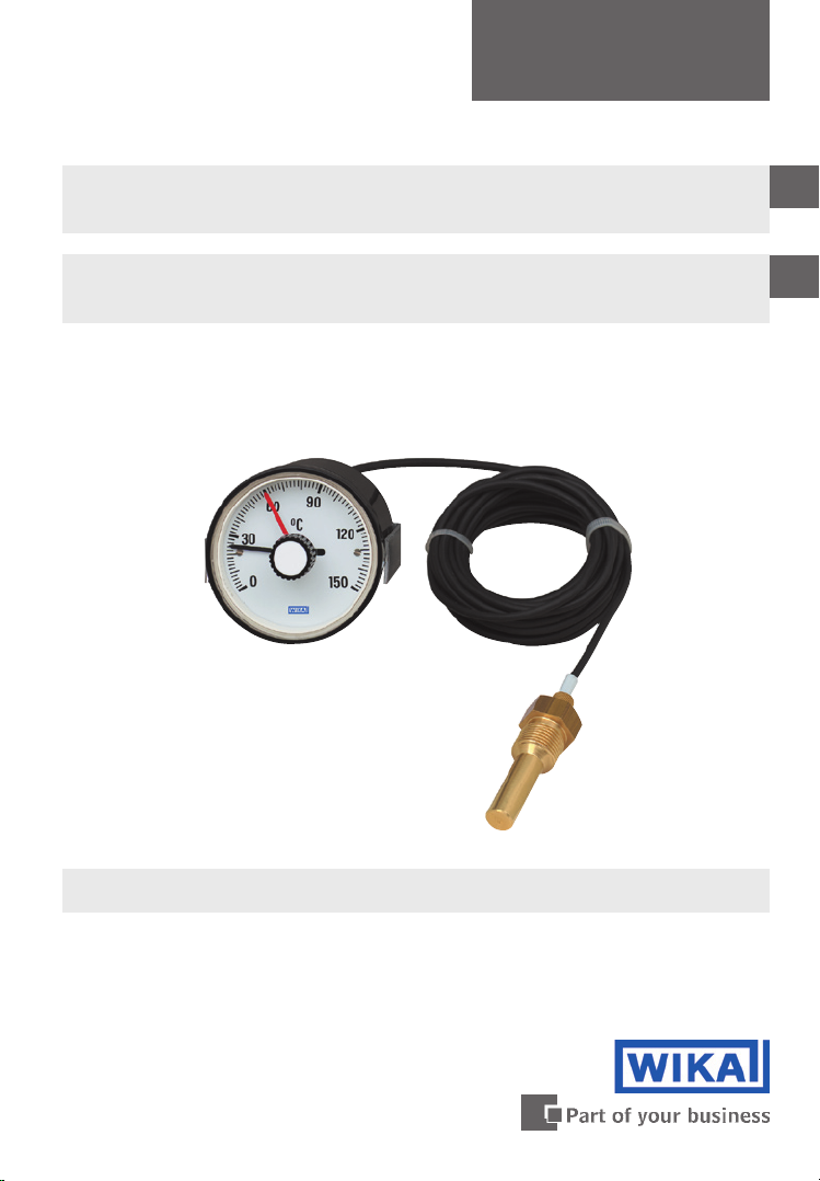
Combistat, mechanical Temperature Regulator
Model SC
Combistat, anzeigender Temperaturregler
Typ SC
GB
D
Combistat, Mechanical Temperature Regulator SC15
Page 2

Operating Instructions Combistat,
GB
mechanical Temperature Regulator Model SC Page 3 - 10
Betriebsanleitung Combistat,
D
anzeigender Temperaturregler Typ SC Seite 11 - 18
11482690 09/2009 GB/D
2
WIKA Operating Instructions Combistat Model SC
Page 3

Contents
Contents
1. Safety instructions 4
2. Application 4
3. Design and operating principle 4
4. Technical data 5
5. Installation, commissioning and operation 6
6. Troubleshooting 8
7. Indicator check 8
8. Indicator correction 9
9. Maintenance and servicing / Cleaning 10
10. Repairs 10
11. Disposal 10
GB
Information
This symbol provides you with information, notes and tips.
Warning!
This Symbol warns you against actions that can cause injury to
people or damage to the instrument.
11482690 09/2009 GB/D
WIKA Operating Instructions Combistat Model SC 3
Page 4

1. Safety instructions / ... / 3. Design, operating principle
1. Safety instructions
The appropriate national safety regulations (e.g. VDE 0100)
GB
Serious injuries and/or damage can occur should the appropriate
regulations not be observed.
Only appropriately qualified personnel should carry out the connection
work.
Any connection work may only be carried out once the equipment has
been isolated.
must be observed when installing, commissioning and
operating these devices.
2. Application
Universally applicable safety temperature regulator for gaseous, liquid and
highly-viscous process media.
3. Design and operating principle
The fluid-filled, closed measuring system consists of a temperature sensor, a
measuring capillary and a bourdon tube. Heating the temperature sensor leads
to a volume change in the closed system and thus a change in the pressure.
This is transferred through a measuring capillary to the bourdon tube and,
through the angular motion of the pointer shaft, to the dial on the display.
When the switch point is passed, the switch disc (cam disc), fitted to the
pointer shaft, triggers the micro switch.
Apart from the standard version with 1 or 2 adjustable micro switches there are
further combinations such as:
1 or 2 non-adjustable micro switches
1 non-adjustable and 1 variable adjustable micro switch
Case steel with 3 or 4 fixed switches
The switch points of the non-adjustable micro switches are printed on the
product label.
WIKA Operating Instructions Combistat Model SC4
11482690 09/2009 GB/D
Page 5

4. Technical Data
4. Technical Data
Ingress protection
Case IP 53, terminals IP 00 (EN 60 529 / IEC 529)
Scale range
100 °C ... 400 °C
Permissible temperatures
Case: +60 °C
Capillary:
plastic sheathed -40 °C ... +100 °C
copper braided -40 °C ... +350 °C
Scale limits
Max. 270 °
Measuring principle
Bourdon tube system
System filling
Xylol, silicon oil, syltherm or nitrogen
Capillary
Plastic sheathed or copper braided,
capillary of copper or stainless steel 1.4571 depending on scale range
p
GB
Capillary length
Max. 10 m
Capillary outlet
Lower back
Contact
Micro switches (fixed or adjustable)
Load data
5 A, 250 V AC
There is no overcurrent protection fitted to these instruments. In order to
prevent the switches being welded through overload, a suitable protection
device should be fitted by the user.
11482690 09/2009 GB/D
WIKA Operating Instructions Combistat Model SC 5
Page 6

4. Technical data / 5. Installation, commissioning, operation
Standard switch differential
< 2 % of the measuring range at the reference temperature of 23 °C at the case
and capillary
GB
Electrical connection
0.8 x 0.63 mm terminal block or AMP plug connection
Case
Plastic (ABS), black or steel
Type of mounting
Panel mounting with clamp
(NS 100: steel case with panel mounting flange)
Options
Panel mounting flange
Protection cap IP 51 or IP 54
Case steel with 3 or 4 fixed micro switches
5. Installation, commissioning and operation
When fitting and using the instruments, the following
fundamental requirements must be followed:
The display range of the safety temperature regulator should be chosen
so that the maximum temperature at the sensor does not exceed the
display range. Also, after the switchpoint has been exceeded, a
resultant reheating process has to be taken into account.
In operation the equipment should not be subjected to strong vibration
or impact loads.
Contamination and high ambient temperature fluctuations should be
avoided.
Any break in the capillary will destroy the instrument and result in it
switching off.
WIKA Operating Instructions Combistat Model SC6
11482690 09/2009 GB/D
Page 7

5. Installation, commissioning and operation
Electrical connection
The connection diagram is shown on the instrument label on the
outer rim of the case.
5.1 Installation condition
Before installing the probe, check whether the probe material used (specified
in the delivery note) is chemically resistant/neutral to the medium being
measured. This also applies to thermowells.
Ensure that all the necessary accessories for the mounting method ordered
have been supplied e.g. instrument mounting brackets, clamp straps for panel
mounting, contact adjustment buttons, etc..
The accessories will be either on the instrument or supplied in a separate bag,
which in most cases will be attached to the thermometer.
If possible, the entire length of the stem should be exposed to the tempera-
ture to be measured, but, if not, it should at least be the length of the active
part (active length), which corresponds to the length of the expansion vessel.
In pipelines or other measuring points the temperature probe should be
directed as far towards the flow as possible.
If a thermowell is used, the stem must not be allowed to touch the bottom of
the thermowell.
GB
Capillaries must be kink protected. The minimum bending radius for
capillaries should not be less than 6 mm. Any kinks or discontinuities in the
capillary may result in the failure of the instrument.
If the probe is installed in a location which is exposed to shock and vibration,
it is essential that the capillary is coiled in several loops, and free of tension
between the last attachment point and the probe. Any excess length should
also be coiled into loops, as cutting the cable would make the instrument
unserviceable.
Any welding or soldering of the capillary, as well as any permanent fastening
of the capillary, must be avoided, as this can severely damage the capillary,
and impair the operation of the instrument.
11482690 09/2009 GB/D
WIKA Operating Instructions Combistat Model SC 7
Page 8

5. Installation, commissioning, operation ... 7. Indicator check
5.2 Ambient conditions
Unless the ingress protection of the thermometer's case is specifically identified
in the order confirmation, the instrument must be protected from humid air and
other aggressive atmospheres.
GB
The ambient temperature at the indicator case should be between 0 °C ... + 40 °C
in order to ensure the best possible measuring accuracy. Higher or lower ambient
temperatures can lead to indication errors
.
6. Troubleshooting
Expansion thermometers with micro switch sare maintenance-free instruments
according to their basic design. As measuring instruments, their measuring
accuracy should be checked at application-specific intervals.
The wear condition of probes exposed to a permanent thermal stress (even
if this stress is very low), of electro-mechanical contacts and of capillaries
exposed to vibratory stress must be checked from time to time.
If any visible damage is found, the instrument must be replaced.
7. Indicator check
Indicator checks should only be carried out in comparison with a more accurate
instrument or, if possible, with a calibrated instrument. The temperature during
the check must remain constant. Fluctuating temperatures can lead to reading
errors caused by the different response times of the probes.
Before checking the indicators of thermometers without thermowells, a waiting
time of at least 5 minutes with the stem‘s full length properly inserted is
required to allow temperature equalisation.
Temperature checks using thermometers with probes assembled with thermowells can, in many cases, only result in a reference temperature at the
instrument under test, due to permanent heat dissipation caused by the
thermowell. In temperature applications fitted with static checking thermometers (e.g. pipeline systems), permanent offsets in reference temperatures can
also be caused by the heat transfer path.
Ambient temperatures around the indicator housing which differ substantially
from room temperature can lead to steady indication errors with constant
ambient temperatures and to varying indication errors with fluctuating ambient
temperatures.
Permanent indication errors caused by the ageing of the measuring system can
be ignored, as they only account for a fraction of the indication accuracy.
WIKA Operating Instructions Combistat Model SC8
11482690 09/2009 GB/D
Page 9

8. Indicator correction
8. Indicator correction
Any interference with or modification to the instrument will
invalidate the warranty!
Indicator corrections may only be carried out by the manufacturer or in
adequately equipped workshops by qualified persons.
Electrical connection should only be carried out by qualified electricians
The switches are terminated on screw terminals or spade plug
Conductor cross-section max. 1.5 mm
The terminal assignment is stated on the connection plate of the thermometer
To adjust red set pointers
The red set pointers are adjustable via the adjustment lock on the window.
The red set pointers for the micro switches are adjustable over the full range
of the instrument. Switching points should be set in the range between 10 %
und 90 % of the full scale, to ensure switching accuracy and the long life of the
measuring mechanism.
The non-adjustable switching points to customer specifications are not
changeable afterwards.
Surface oxidation at the contact areas may lead to malfunction, which can
result in contact-arcing, particularly in the case of intrinsically safe circuits (low
voltages and currents), and in the case of relatively high contact loads.
2
GB
11482690 09/2009 GB/D
WIKA Operating Instructions Combistat Model SC 9
Page 10

9. Maintenance and servicing, cleaning ... 11. Disposal
9. Maintenance and servicing / cleaning
The instruments require no maintenance or servicing.
The indicator and switching function should be checked once or twice every
GB
12 months. For this the instrument must be disconnected from the process and
checked using a temperature calibrator.
The instruments should be cleaned with a damp cloth, moistened with soap
solution. When cleaning the mains power must be disconnected. All parts must
be dry before the power is reconnected.
10. Repairs
Repairs are only to be carried out by the manufacturer or appropriately trained
personnel.
For further details see WIKA data sheet TV 28.02.
11. Disposal
Disposal of instrument components and packaging materials should be in
accordance with the respective waste treatment and disposal regulations of the
region or country to which the instrument is supplied.
10
11482690 09/2009 GB/D
WIKA Operating Instructions Combistat Model SC
Page 11

Inhalt
Inhalt
1. Sicherheitshinweise 12
2. Anwendung 12
3. Aufbau und Wirkungsweise 12
4. Technische Daten 13
5. Montage, Inbetriebnahme und Betrieb 14
6. Maßnahmen zur Störungsbeseitigung 16
7. Anzeigekontrolle 16
8. Anzeigekorrektur 17
9. Wartung 18
10. Reparaturen 18
11. Entsorgung 18
D
Information
Dieses Zeichen gibt Ihnen Informationen, Hinweise oder Tipps.
Warnung!
Dieses Symbol warnt Sie vor Handlungen, die Schäden an
Personen oder am Gerät verursachen können.
11482690 09/2009 GB/D
WIKA Betriebsanleitung Combistat Typ SC 11
Page 12

1. Sicherheitshinweise ... 3. Aufbau und Wirkungsweise
1. Sicherheitshinweise
Beachten Sie unbedingt bei Montage, Inbetriebnahme und
Betrieb dieser Geräte die entsprechenden nationalen Sicherheitsvorschriften (z. B. VDE 0100).
Bei Nichtbeachten der entsprechenden Vorschriften können schwere
D
Körperverletzungen und/oder Sachschäden auftreten.
Nur entsprechend qualifiziertes Personal darf die Anschlussarbeiten
durchführen.
Alle Anschlussarbeiten dürfen nur im spannungslosen Zustand durch-
geführt werden.
2. Anwendung
Universell einsetzbarer anzeigender Temperaturregler für gasförmige, flüssige
und hochviskose Messstoffe.
3. Aufbau und Wirkungsweise
Das flüssigkeitsgefüllte, geschlossene Messsystem besteht aus einem
Temperaturfühler, Messleitung und Bourdonfeder. Die durch die Wärmebeaufschlagung am Temperaturfühler erzeugte Volumenänderung und somit
auch die Druckänderung im geschlossenen System wird durch die Messleitung
zur Bourdonfeder übertragen und über den Winkelausschlag der Zeigerwelle
auf dem Zifferblatt zur Anzeige gebracht.
Die auf der Zeigerwelle angeordnete Schaltscheibe (Kurvenscheibe) löst bei
Erreichen des Schaltpunktes den Schaltvorgang am Mikroschalter aus.
Neben der Standardversion mit 1 oder 2 verstellbaren Mikroschaltern gibt es
weitere Kombinationen wie:
1 oder 2 fest eingestellte Mikroschalter
1 fest und 1 variabel eingestellter Mikroschalter
Blechgehäuse mit 3 oder 4 fest eingestellten Mikroschaltern
Die Schaltpunkte der fest eingestellten Mikroschalter sind auf dem Typenschild
vermerkt.
WIKA Betriebsanleitung Combistat Typ SC12
11482690 09/2009 GB/D
Page 13

4. Technische Daten
4. Technische Daten
Schutzart
Gehäuse IP 53, Klemmen IP 00 (EN 60 529 / IEC 529)
Anzeigebereich
100 °C ... 400 °C
Zulässige Temperaturen
Gehäuse: +60 °C
Messleitung:
kunststoffummantelt -40 °C ... +100 °C
kupferumsponnen -40 °C ... +350 °C
Skalenlänge
Max. 270 °
Messprinzip
Bourdonfedersystem
Füllmedium
Xylol, Silikonöl, Syltherm oder Stickstoff
Messleitung
Kunststoffummantelt oder kupferumsponnen,
Kapillare aus Kupfer oder CrNi-Stahl 1.4571 je nach Anzeigebereich
p
D
Messleitungslänge
Max. 10 m
Messleitungsaustritt
Rückseitig exzentrisch
Kontakt
Mikroschalter (fest oder einstellbar)
Lastdaten
5 A, 250 V AC
In den Geräten sind keine Überstrom-Schutzeinrichtungen eingebaut. Um
ein Verschweißen der Schalter durch Überlast zu verhindern sind geeignete
Schutzeinrichtungen vom Anwender vorzusehen.
11482690 09/2009 GB/D
WIKA Betriebsanleitung Combistat Typ SC 13
Page 14

4. Technische Daten / 5. Montage, Inbetriebnahme, Betrieb
Standardschaltdifferenz
< 2 % des Messbereiches bei Referenztemperatur von 23 °C auf Gehäuse und
Messleitung
Elektrischer Anschluss
Flachstecker 0,8 x 0,63 mm oder Klemmanschluss
Gehäuse
D
Kunststoff (ABS), schwarz oder Stahl
Befestigungsart
Tafeleinbau mit Befestigungsbügel
(NG 100: Stahlblechgehäuse mit Befestigungsrand vorne)
Optionen
Befestigungsrand vorne
Schutzkappe IP 51 oder IP 54
Blechgehäuse mit 3 oder 4 festen Mikroschaltern
5. Montage, Inbetriebnahme und Betrieb
Für die Montage und den Betrieb der Geräte sind folgende,
grundsätzliche Anforderungen zu beachten:
Der Anzeigebereich des Temperatrurregelgerätes sollte so gewählt
werden, dass die maximal am Fühler anliegende Temperatur den
Anzeigebereich nicht überschreitet. Dabei sind auch nach überschreiten
des Schaltpunktes auftretende Nachheizvorgänge zu beachten.
In Betrieb sollte das Gerät keinen starken Schwingungen und Stoß-
belastungen ausgesetzt sein.
Verschmutzungen und hohe Umgebungstemperaturschwankungen sind
zu vermeiden.
Ein Durchtrennen der Messleitung führt zur Zerstörung des Gerätes und
zur Abschaltung.
14
WIKA Betriebsanleitung Combistat Typ SC
11482690 09/2009 GB/D
Page 15

5. Montage, Inbetriebnahme und Betrieb
Elektrischer Anschluss
Die Klemmenbelegung ist auf dem Typenschild am Gehäuseumfang
angegeben.
5.1 Einbaubedingungen
Vor der Montage des Fühlers ist zu prüfen, ob der verwendete Fühlerwerkstoff
(aus dem Lieferschein ersichtlich) gegenüber dem Messmedium chemisch
beständig/neutral ist. Dies gilt auch für Schutzrohre.
Es ist darauf zu achten, dass das je nach Gehäusebefestigungsart notwendige
Zubehör für die Tafeleinbaubefestigung vorhanden ist.
Das Zubehör ist angebaut oder befindet sich in einem am Thermometer
befestigten Beutel.
Der Tauschaft soll möglichst mit seiner ganzen Länge der zu messenden
Temperatur ausgesetzt sein. Mindestens aber die Länge des aktiven Teils,
welche der Länge der Ausdehnungsgefäßes entspricht (aktive Länge).
Der Temperaturfühler muss in Rohrleitungen oder sonstigen Messstellen der
Strömungsrichtung möglichst schräg entgegengerichtet stehen.
Bei der Verwendung von Schutzrohren ist zu beachten, dass der Tauchschaft
nicht den Boden des Schutzrohres berühren darf.
D
Fernleitungen sind vor Knickungen zu schützen. Der kleinste Biegeradius der
Fernleitung sollte 6 mm nicht unterschreiten. Knickung oder Unterbrechung
der Fernleitung führen zum Ausfall des Gerätes.
Ist der Fühler an einer erschütterten oder vibrierenden Stelle eingebaut, so
ist die Fernleitung unbedingt zwischen dem letzten Befestigungspunkt und
dem Fühler in mehreren Schlaufen freischwingend zu verlegen. Überlängen
sind ebenfalls als Schlaufen zu verlegen, da das Abschneiden das Gerät
unbrauchbar macht.
Das Anschweißen oder Löten der Fernleitung, sowie alle unlösbaren Befesti-
gungen der Fernleitung sind zu vermeiden, da hierbei die Fernleitung stark
beschädigt und die Funktion des Gerätes beeinträchtigt werden kann.
11482690 09/2009 GB/D
WIKA Betriebsanleitung Combistat Typ SC 15
Page 16

6. Maßnahmen zur Störungsbeseitigung / 7. Anzeigekontrolle
5.2 Umgebungsbedingungen
Thermometer, deren Gehäuseschutzart nicht besonders in der Auftragsbestätigung gekennzeichnet ist, sind vor feuchter Luft und sonstiger
aggressiver Atmosphäre zu schützen.
Die Umgebungstemperatur am Anzeigegehäuse sollte sich innerhalb von
0 °C … +40 °C bewegen, um die größte Messgenauigkeit zu gewährleisten.
Höhere bzw. niedrigere Umgebungstemperaturen können zu Anzeigefehlern
D
führen.
6. Maßnahmen zur Störungsbeseitigung
Tensions-Thermometer mit Mikroschalter sind ihrer Grundkonstruktion
entsprechend wartungsfreie Geräte. Als messende Geräte sollte man sie in
applikationsabhängigen Zeitabständen auf Messgenauigkeit kontrollieren.
Temperaturfühler, die einer dauernden, wenn auch geringfügigen thermischen
Beanspruchung unterworfen sind, elektromechanische Kontakte, sowie
bewegte Kapillarleitungen sind von Zeit zu Zeit auf den Verschleißzustand zu
kontrollieren.
Bei sichtbarer Beschädigung ist das Gerät auszutauschen.
7. Anzeigekontrolle
Die Anzeigekontrolle sollte nur im Vergleich zu einem genaueren oder möglichst
kalibrierten Gerät erfolgen. Die Kontrolltemperatur muss konstant sein.
Bei veränderlichen Temperaturen entstehen Ablesefehler, die ihre Ursache in
unterschiedlichen Ansprechzeiten der Fühler haben.
Bei Thermometern ohne Schutzrohr muss bei voller ordnungsgemäßer
Eintauchlänge eine Mindestwartezeit von 5 Minuten zum Temperaturausgleich
eingehalten werden.
Temperaturkontrollen, bei denen die Fühler in Schutzrohren eingebaut sind,
können in vielen Fällen nur eine Bezugstemperatur am Prüfling ergeben, da
durch das Schutzrohr bleibende Wärmeableitungen entstehen. In Temperaturfeldern, die mit stationären Kontrollthermometern ausgerüstet sind (z. B.
Rohrleitungssysteme) können ebenfalls Bezugstemperaturen mit bleibender
Abweichung entstehen, deren Ursache in der Messstrecke liegt. Sehr stark
von der Raumtemperatur abweichende Umgebungstemperaturen am Anzeigegehäuse können bei konstanten Umgebungstemperaturen zu bleibenden,
bei veränderlichen Umgebungstemperaturen zu wechselnden Anzeigefehlern
führen.
Bleibende Anzeigefehler durch Nachalterung des Messsystems sind vernachlässigbar, da sie nur einen Bruchteil der Anzeigegenauigkeit betragen.
16
WIKA Betriebsanleitung Combistat Typ SC
11482690 09/2009 GB/D
Page 17

8. Anzeigekorrektur
8. Anzeigekorrektur
Bei Eingriffen jeglicher Art in das Gerät erlischt der Garantieanspruch!
Eine Anzeigekorrektur kann nur beim Hersteller bzw. in entsprechend eingerichteten Werkstätten durch qualifiziertes Personal erfolgen.
Der elektrische Anschluss darf nur durch qualifiziertes Personal erfolgen
Anschluss der Schalter über Schraubklemmen oder Flachstecker
D
Leitungsquerschnitt max. 1,5 mm
Klemmenbelegung auf Anschlussschild am Thermometer
Einstellen der Sollwertzeiger
Das Einstellen der Sollwerte erfolgt über das Verstellschloss in der Sichtscheibe.
Die Sollwertzeiger der Mikroschalter sind im gesamten Skalenbereich frei
einstellbar. Aus Gründen der Schaltgenauigkeit und der Lebensdauer der
mechanischen Messsysteme sollen die Schaltpunkte zwischen 10 % und 90 %
der Messspanne liegen.
Die auf Kundenwunsch fest eingestellten Schaltpunkte sind nachträglich nicht
mehr veränderbar.
Infolge von Oberflächenoxydation an den Kontaktflächen können sich
Störungen ergeben, die besonders bei eigensicheren Schaltungen (kleine
Spannungen und geringe Ströme) infolge des entstehenden lsolationswiderstandes und bei höheren Kontaktbelastungen zu Kontaktbrand führen können.
2
11482690 09/2009 GB/D
WIKA Betriebsanleitung Combistat Typ SC 17
Page 18

9. Wartung, Reinigung / 10. Reparaturen / 11. Entsorgung
9. Wartung / Reinigung
Die Geräte sind wartungsfrei.
Eine Überprüfung der Anzeige und der Schaltfunktion sollte etwa 1 bis 2 mal
pro Jahr erfolgen. Dazu ist das Gerät vom Prozess zu trennen und mit einem
Temperaturkalibrator zu kontrollieren.
Reinigen der Geräte mit einem (in Seifenlauge) angefeuchteten Tuch.
D
Zur Reinigung sind die Leitungen vom Netz zu trennen. Vor Wiedereinschalten
des Stromes ist sicherzustellen, dass alle Teile abgetrocknet sind.
10. Reparaturen
Reparaturen sind ausschließlich vom Hersteller oder entsprechend qualifiziertes
Personal durchzuführen.
Weitere technische Daten siehe WIKA Datenblatt TV 28.02.
11. Entsorgung
Entsorgen Sie Gerätekomponenten und Verpackungsmaterialien entsprechend
den einschlägigen landesspezifischen Abfallbehandlungs- und Entsorgungsvorschriften des Anliefergebietes.
18
11482690 09/2009 GB/D
WIKA Betriebsanleitung Combistat Typ SC
 Loading...