

Page 1
Electronic
Pressure Measurement
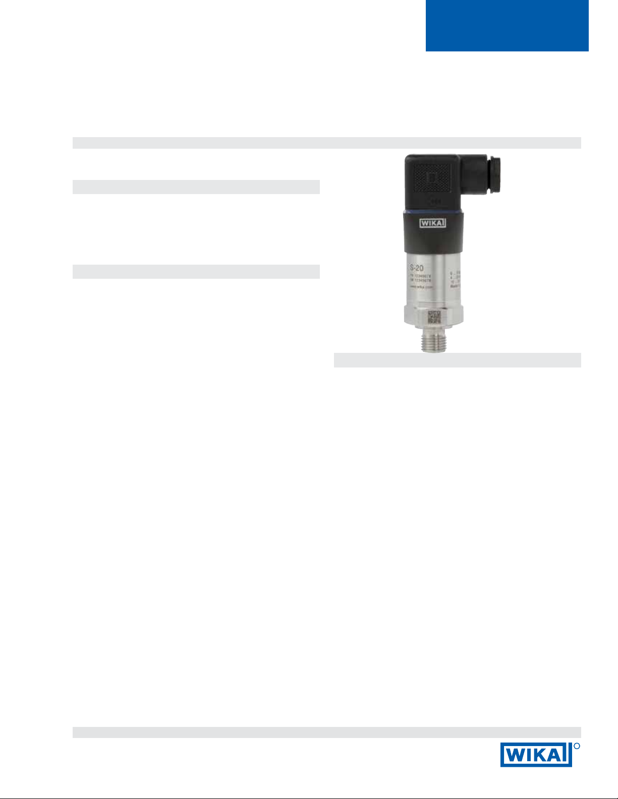
Model S-20
High Performance Pressure Transmitter
for General Industrial Applications
WIKA Datasheet S-20
Applications
■
General industrial applications
■
Demanding research and development applications
■
Harsh industrial environments
Special Features
■
Measuring ranges from 0…10 to 0…20,000 psi (0 ... 0.4
to 0 ... 1,600 bar)
■
Non-linearity of up to 0.125 % B.F.S.L.
■
Available output signals include 4 ... 20 mA, 0 ... 10 VDC,
1 ... 5 VDC and many others
■
Industry standard electrical connections including
DIN 175301-803A L- connector, cables, housings and
many others
■
Common USA and international process connections
available
Model S-20 Pressure Transmitter
Description
The model S-20 pressure transmitter is the ideal solution for
customers with demanding performance requirements in
many industrial applications.
It features high accuracy, a robust design and is available with
an exceptional number of options that make it suitable for an
extremely broad range of pressure measurement applications.
.
High versatility
The model S-20 oers continuous measuring ranges between
0…10 psi and 0…20,000 psi (0 ... 0.4 and 0 ... 1,600 bar) in
all common engineering units. Vacuum and compound ranges
are also available.
These measuring ranges can be combined with virtually any
standard industry output signal, common international process
connections and a wide variety of electrical connections.
A large number of options are available including dierent
accuracy classes, extended temperature ranges and
customer specic pin assignments to provide compatibility
with most industrial applications.
Data sheets showing similar products:
Pressure transmitter for general industrial applications; model A-10; see data sheet PE 81.60
High quality
The rugged design makes the model S-20 a highly reliable
transmitter that is not aected by most adverse environmental
conditions. This transmitter meets most application
performance requirements when exposed to very low outdoor
temperatures, extreme shock and vibration and aggressive
media.
Availability
Variations of the S-20 described in this data sheet are usually
available with short lead times. Inventory of popular designs
are usually available for particularly urgent requirements.
Page 1 of 15WIKA Datasheet S-20 · 4/2013
R
Page 2
Measuring ranges
Relative pressure ranges
psi 0 … 10 0 … 15 0 … 25 0 … 30 0 … 50 0 … 60 0 … 100
0 … 150 0 … 160 0 … 200 0 … 250 0 … 300 0 … 400 0 … 500
0 … 600 0 … 750 0 … 1,000 0 … 1,500 0 … 2,000 0 … 3,000 0 … 4,000
0 … 5,000 0 … 6,000 0 … 7,500 0 … 10,000 0 … 15,000 0 … 20,000
bar 0 ... 0.4 0 ... 0.6 0 … 1 0 … 1.6 0 … 2.5 0 … 4 0 … 6
0 … 10 0 … 16 0 … 25 0 … 40 0 … 60 0 … 100 0 … 160
0 … 250 0 …. 400 0 … 600 0 … 1,000 0 … 1,600
Absolute pressure ranges
psi 0 … 10 0 … 15 0 … 25 0 … 30 0 … 50 0 … 60 0 … 100
0 … 150 0 … 160 0 … 200 0 … 250 0 … 300 0 … 400 0 … 500
bar 0 … 0.4 0 … 0.6 0 … 1 0 … 1.6 0 … 2.5 0 … 4 0 … 6
0 … 10 0 … 16 0 … 25 0 … 40
Vacuum and compound ranges
psi -30 inHg ... 0 -30 inHg ... +15 -30 inHg ... +30 -30 inHg ... +45 -30 inHg ... +60
-30 inHg ... +100 -30 inHg ... +160 -30 inHg ... +200 -30 inHg ... +300 -30 inHg ... +500
bar -0.4 … 0 -0.6 … 0 -1 … 0 -1 … +0.6 -1 … +1.5
-1 … +3 -1 … +5 -1 … +9 -1 … +15 -1 … +24
-1 … +39 -1 … +59
The listed pressure ranges are also available in kg/cm2, kPa and MPa.
Special measuring ranges between 0 ... 10 and 0 ... 20,000 psi ( 0.4…1600 bar) are available on request.
Special pressure ranges may have reduced long-term stability and increased temperature errors.
Overpressure limit
The overpressure limit depends on the specic sensor element used for the selected pressure range. A reduction in the
overpressure safety rating may occur depending on the specic process connection and seal selected. A higher overpressure
limit may provide a greater temperature error.
Measuring range < 150 psi/10 bar ≥ 150 psi/10 bar
3 times (standard) 2 times
5 times 3 times
1) Restriction: max. 60 bar/870 psi with absolute pressure
2) Only possible for relative pressure measuring ranges ≤ 400 bar or 5,800 psi
3) Only possible for absolute pressure measuring ranges < 16 bar or 220 psi
1)
(standard)
2) 3)
Vacuum resistance
Ye s
(No damage to sensor when vacuum is applied)
Page 2 of 15 WIKA Datasheet S-20 · 4/2013
Page 3

Output signal
Signal type Signal
Current (2-wire) 4 ... 20 mA
20 ... 4 mA
Voltage (3-wire) DC 0 ... 10 V
DC 0 ... 5 V
DC 1 ... 5 V
DC 0.5 ... 4.5 V
DC 1 ... 6 V
DC 10 ... 0 V
Ratiometric (3-wire) DC 0.5 ... 4.5 V
Other output signals on request.
Permissible load in Ω
■
Current output (2-wire): ≤ (power supply - 7.5 V) / 0.023 A
≤ (power supply - 11.5 V) / 0.023 A (with optional settling time of 1 ms)
■
Voltage output (3-wire): > maximum output voltage / 1 mA
■
Ratiometric output (3-wire): > 4.5k
Optional output signal limits
■
4 ... 20 mA signal: Minimum zero point setting: 3.6 mA 1), 3.8 mA, 4.0 mA
Maximum full scale setting: 20 mA, 21.5 mA, 23 mA
■
DC 0 ... 10 V signal: Full scale: 10 VDC or 11.5 VDC
1) Not available with the zero point adjustment option
Voltage supply
Power supply
Maximum allowable power supply rating for cULus approval: 35 VDC (32 VDC with heavy-duty connector)
■
Current output (2-wire)
4 ... 20 mA: 8 ... 36 VDC (12 ... 36 VDC with optional 1 ms settling time)
20 ... 4 mA (reverse output): 8 ... 36 VDC
■
Voltage output (3-wire)
0 ... 10 VDC: 12 ... 36 VDC
0 ... 5 VDC: 8 ... 36 VDC
1 ... 5 VDC: 8 ... 36 VDC
0.5 ... 4.5 VDC: 8 ... 36 VDC
1 ... 6 VDC: 9 ... 36 VDC
10 ... 0 VDC: 12 ... 36 VDC
■
3-wire ratiometric output:
0.5 ... 4.5 VDC: 5 VDC ±10 %
Power dissipation (loss)
■
Current output (2-wire): 828 mW (22 mW/K derating of the power dissipation when ambient temperatures
are ≥ 212 ° F/100 °C)
■
Voltage output (3-wire): 432 mW
Maximum current consumption
■
Current output (2-wire): Current signal, max. 25 mA
■
Voltage output (3-wire): max. 12 mA
Page 3 of 15WIKA Datasheet S-20 · 4/2013
Page 4

Reference conditions (per IEC 61298-1)
Temperature
59…77ºF (15…25ºC)
Barometric pressure
860 ... 1,060 mbar
Humidity
45 ... 75 % relative
Power supply
■
24 VDC
■
5 VDC for ratiometric output
Mounting position
Calibrated in vertical position with pressure connection facing down
Response time
Signal type Settling time per IEC 62594 Signal damping
Standard
Current (2-wire) 3 ms 1 ms 10, 50, 100, 500, 1,000, 5,000 ms
Voltage (3-wire) 2 ms 1 ms 10, 50, 100, 500, 1,000, 5,000 ms
Ratiometric (3-wire) 2 ms 1 ms 10, 50, 100, 500, 1,000, 5,000 ms
1) 3 dB limit frequency: 500 Hz
2) 3 dB limit frequency: 1,000 Hz
3) Alternative specications for 4 ... 20 mA output signal:
Load: ≤ (power supply - 11.5 V) / 0.023 A
Power supply: DC 12 ... 36 V
1)
Option 1
2) 3)
Option 2
Switch-on time (from power up to output signal)
150 ms
Switch-on drift time
5 s to reach stated accuracy (60 s with optional 0.1 % zero point adjustment)
Page 4 of 15 WIKA Datasheet S-20 · 4/2013
Page 5
Accuracy data
Non-linearity (per IEC 61298-2)
Accuracy at calibration temperature
BFSL Terminal method
≤ ±0.5 % of span (standard) ≤ ±1.0 % of span ≤ ±1.0 % of span
≤ ±0.25 % of span ≤ ±0.5 % of span ≤ ±0.5 % of span
≤ ±0.125 % of span
1) Restrictions for the non-linearity of 0.125 % BFSL or 0.25 % with terminal method:
Available output signals: 4 ...20 mA and DC 0 ... 10 V
Available measuring ranges: All measuring ranges specied in the data sheet
For further output signals or measuring ranges, please ask the manufacturer
1)
≤ ±0.25 % of span
1)
≤ ±0.25 % of span
Calibration temperature
15 ... 25 °C (standard)
4 °C ±5 °C
40 °C ±5 °C
60 °C ±5 °C
80 °C ±5 °C
Zero point adjustment
≤ ±0.2 % of span, factory setting (standard)
≤ ±0.1 % of span, factory setting
±10 % of span, in 0.05 % increments, customer setting
1) Restrictions for the optional factory set 0.1 % zero point adjustment:
Only available with 4 ...20 mA and 0 ... 10 VDC output signals
Available measurement ranges: All relative pressure ranges specied in the
data sheet. Not available in combination with the optional calibration temperature.
2) The “optional zero point adjustment access” is not available with every electrical
connection, see “Electrical connections” for details.
1)
2)
1)
Eect of mounting position on zero oset
For measuring ranges < 15 psi ( 1 bar), an additional zero oset of up to 0.15 % applies
Non-repeatability
≤ ±0.1 % of span
Temperature hysteresis
0.1 % of span at > 176 °F (80 °C)
Long-term drift (per IEC 61298-2)
■
≤ ±0.1 % of span
■
≤ ±0.2 % of span (with special measuring ranges)
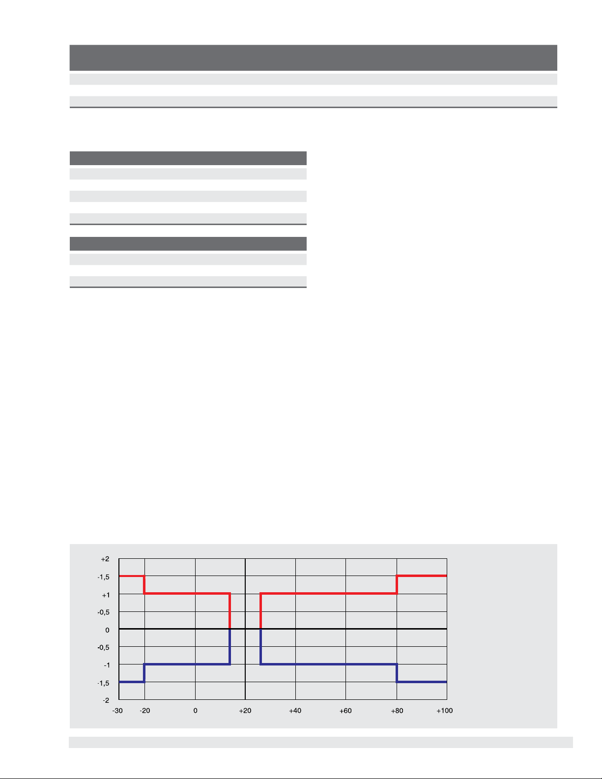
Temperature error (for calibration temperature of 59…77 °F (15 ... 25 °C))
For measuring ranges < 15 psi (1 bar), special measuring ranges and instruments with an increased overpressure limit the
temperature error increases by 0.5 % of span
Temperature error [%]
Medium temperature [°C]
Page 5 of 15WIKA Datasheet S-20 · 4/2013
Page 6

Operating conditions
Permissible temperature ranges
Medium Ambient Design maximum permissible pressure
-30 ... +100 °C (standard) -30 ... +100 °C - -
-40 ... +125 °C -40 ... +125 °C - -
-40 ... +150 °C -40 ... +125 °C
-40 ... +200 °C -40 ... +125 °C
-20 ... +60 °C -20 ... +60 °C Oxygen applications -
1) Derating curve and formula (see following diagram)
There may be other media and ambient temperature limitations depending upon the sealing material used with the process
connection and the specic electrical connection selected.
For restrictions see "Process connections, sealings" and "Electrical connections".
1)
1)
with integrated cooling element 5800 psi (400 bar)
with integrated cooling element 5800 psi (400 bar)
Ambient temperature [°C]
Medium temperature [°C]
Maximum permissible ambient temperature
T
(T
amb
T
amb
T
= ambient temperature [°C]
amb
= medium temperature [°C]
T
med
< 125 °C) = 125 °C
med
(T
≥ 125 °C) = -0.62 x T
med
med
+ 202 °C
Maximum permissible medium temperature
T
(T
< 80 °C) = 200 °C
amb
(T
≥ 80 °C) = -1.61 x T
amb
amb
+ 326 °C
T
med
med
Storage and transport conditions
■
Permissible temperature range: -40…158° F (-40 ... +70 °C)
■
Maximum humidity (per IEC 68-2-78): 67 % r.h. at 104 F (40 °C) (in accordance with 4K4H per EN 60721-3-4)
Vibration resistance (per IEC 68-2-6)
20 g, 10 ... 2,000 Hz, (40 g, 10 ... 2,000 Hz for heavy-duty connector)
For instruments with cooling elements a limited vibration resistance of 10 g applies (10 ... 2,000 Hz)
Continuous vibration resistance (per IEC 68-2-6)
10 g
Shock resistance (per IEC 68-2-27)
100 g, 6 ms (500 g, 1 ms for heavy-duty connector)
Service life
100 million load cycles (10 million load cycles for measuring ranges > 7,500 psi /600 bar)
Free-fall test (following IEC 60721-3-2)
■
Individual packaging: 5 ft (1.5 m)
■
Multiple packaging: 1.6 ft (0.5 m)
■
PE bag: 1.6 ft (0.5 m)
Page 6 of 15 WIKA Datasheet S-20 · 4/2013
Page 7

Process connections
Available connections
Process connection per Thread size Maximum overpressure limit
EN 837 G ⅛ B 11,600 psi (800 bar)
G ¼ B 20,300 psi (1,400 bar)
G ¼ B female 20,300 psi (1,400 bar)
G ½ B 26,100 psi (1,800 bar) (1.4404)
46,400 psi (3,200 bar) (1.4542)
G ⅜ B 20,300 psi (1,400 bar)
DIN 3852-E G ¼ A 8700 psi (600 bar)
G ½ A 8700 psi (600 bar)
M14 x 1.5 8700 psi (600 bar)
ISO 228 M20 x 1.5 26,100 psi (1,800 bar) (1.4404)
47,800 psi (3,300 bar) (1.4542)
M12 x 1.5 8700 psi (600 bar)
SAE J514 E 7/16-20 UNF BOSS 8700 psi (600 bar)
7/16-20 UNF J514 sealing cone 74° 15,900 psi (1,100 bar)
9/16-18 UNF BOSS 8700 psi (600 bar)
ANSI/ASME B1.20.1 ⅛ NPT 15,900 psi (1,100 bar)
¼ NPT 21,700 psi (1,500 bar)
¼ NPT female 21,700 psi (1,500 bar)
½ NPT 21,700 psi (1,500 bar) (1.4404)
40,600 psi (2,800 bar) (1.4542)
KS PT ¼ 23,200 psi (1,600 bar)
PT ½ 21,700 psi (1,500 bar)
PT ⅜ 20,300 psi (1,400 bar)
ISO 7 R ¼ 23,200 psi (1,600 bar)
R ⅜ 21,700 psi (1,500 bar)
R ½ 20,300 psi (1,400 bar) (1.4404)
41,200 psi (2,840 bar) (1.4542)
Other process connections available on request.
Pressure port diameter
Pressure port diameter Available for thread sizes
2.5 mm (standard) all thread sizes
0.3 mm G ¼ A, G ½ A, ¼ NPT, ½ NPT, R ¼, 7/16-20 UNF BOSS
0.6 mm G ¼ A, G ½ A, ¼ NPT, ½ NPT, R ¼, 7/16-20 UNF BOSS
6 mm* G ¼ A, ¼ NPT, R ¼, 7/16-20 UNF BOSS
12 mm* G ½ A, ½ NPT
*6 or 12 mm enlarged pressure port is only available for measuring ranges up to and including 0 ... 500 psi (0 ... 40 bar).
Sealing rings
Process connection per Copper Stainless steel NBR FKM
-40 ... +125 °C -40 ... +125 °C -20 ... +100 °C -15 ... +125 °C
EN 837 Standard Option - DIN 3852-E - - Standard Option
ISO 228 Standard Option - SAE J514 E
-
- Standard Option
Page 7 of 15WIKA Datasheet S-20 · 4/2013
Page 8

Electrical connections
Available connections
Electrical connection Ingress
protection
Wire
cross-sec-
Cable ∅ Cable
material
maximum permissible
temperature
tion
L-connector DIN 175301-803 A
L-connector DIN 175301-803 C
Circular connector M12 x 1 (4-pin)
Circular connector M12 x 1 (4-pin, metallic) IP 67 - - - -40 ... +125 °C (cULus: +85 °C)
Bayonet connector (6-pin) IP 67 - - - -40 ... +125 °C
Field case IP 6K9K - - - -25 ... +100 °C
Heavy-duty connector
Cable outlet IP 67
2)
1)
Cable outlet ½ NPT conduit IP 67 6 x 0.35 mm
Cable outlet IP 68 IP 68 6 x 0.35 mm
Cable outlet IP 68, FEP IP 68 6 x 0.39 mm
Cable outlet IP 6K9K IP 6K9K 6 x 0.35 mm
1) Customer zero point adjustment available as an option.
2) max. DC 32 V with cULus approval
1)
1)
1)
IP 65 - - - -30 ... +100 °C
IP 65 - - - -30 ... +100 °C
IP 67 - - - -30 ... +100 °C
IP 68 - - - -40 ... +125 °C
IP 67 3 x 0.34 mm25.5 mm PUR -30 ... +100 °C
2
6.1 mm PUR -30 ... +100 °C (cULus: +90 °C)
2
6.1 mm PUR -30 ... +125 °C (cULus: +90 °C)
2
5.8 mm FEP -40 ... +125 °C (cULus: +105 °C)
2
6.1 mm PUR -30 ... +125 °C (cULus: +90 °C)
Other connections on request.
Assembly congurations of the mating connectors
Mating connector for electrical
connection
L-connector DIN 175301-803 A
■
Mating connector IP 65 max. 1.5 mm26 ... 8 mm - -40 ... +125 °C -
■
Mating connector (conduit) IP 65 max. 1.5 mm2- - -40 ... +125 °C -
■
Mating connector with molded
cable
■
Mating connector with molded
cable, shielded
L-connector DIN 175301-803 C
■
Mating connector IP 65 max. 0.75 mm24.5 ... 6 mm - -40 ... +125 °C -
■
Mating connector with molded
cable
Circular connector M12 x 1 (4-pin)
■
Mating connector, straight, with
molded cable
■
Straight mating connector, with
molded cable, shielded
■
Mating connector, angled, with
molded cable
Heavy-duty connector
■
Mating connector with cable IP 68 6 x 0.14 mm26.5 mm PUR -40 ... +125 °C
Ingress
protection
IP 65 3 x 0.75 mm26 mm PUR -40 ... +125 °C
Wire
cross-section
Cable ∅ Cable
material
max. permissible
temperature
Cable ends
no nishing
(cULus: -25 ... +85°C)
IP 65 6 x 0.5 mm
2
6.8 mm PUR -25 ... +85 °C End splices
IP 65 4 x 0.75 mm25.9 mm PUR -25 ... +85 °C no nishing
IP 67 3 x 0.34 mm24.3 mm PUR -25 ... +80 °C no nishing
IP 67 3 x 0.34 mm24.3 mm PUR -25 ... +80 °C no nishing
IP 67 3 x 0.34 mm25.5 mm PUR -25 ... +80 °C no nishing
no nishing
(cULus: -30 ... +90°C)
Assembly congurations of the cable outlets
Electrical connection Unnished wire ends Tinned wire ends with end splices
Cable outlet IP 67 Standard Option Option
Cable outlet ½ NPT conduit - Option Standard
Cable outlet IP 68 - Option Standard
Cable outlet IP 68, FEP - Option Standard
Cable outlet IP 6K9K - Option Standard
Cable lengths of 6 ft, 15 ft, 2 m or 5 m are available, other cable lengths on request.
Page 8 of 15 WIKA Datasheet S-20 · 4/2013
Page 9

Connection diagrams
L-connector DIN 175301-803 A
U
+
U
-
S
+
Shield (option) 4 4
L-connector DIN 175301-803 C
U
+
U
-
S
+
Shield (option) 4 4
Bayonet connector (6-pin)
U
+
U
-
S
+
Shield Case Case
2-wire 3-wire
1 1
2 2
- 3
2-wire 3-wire
1 1
2 2
- 3
2-wire 3-wire
A A
B B
- C
Heavy-duty connector
U
+
U
-
S
+
Shield Case Case
Circular connector M12 x 1 (4-pin)
U
+
U
-
S
+
Shield (option) Case Case
Field case
U
+
U
-
S
+
Shield 5 5
2-wire 3-wire
1 1
2 2
- 3
2-wire 3-wire
1 1
3 3
- 4
2-wire 3-wire
1 1
2 2
- 3
Cable outlet
incl. mating connector with molded cable
2-wire 3-wire
U
+
U
-
S
+
Shield grey (GY) grey (GY)
brown (BN) brown (BN)
blue (BU) blue (BU)
- black (BK)
Cable outlet
(US code)
Other pin assignments on request.
Electrical protection
The electrical protection measures below do not apply to ratiometric output signals.
■
Short-circuit protection: S+ vs. U
■
Reverse polarity protection: U+ vs. U
■
Overvoltage protection: 40 VDC
■
Insulation voltage: 750 VDC
-
-
2-wire 3-wire
U
+
U
-
S
+
Shield grey (GY) grey (GY)
red (RD) red (RD)
black (BK)
- white (WH)
black (BK)
Page 9 of 15WIKA Datasheet S-20 · 4/2013
Page 10

Materials
Wetted parts
■
Relative measuring ranges:
- Measuring ranges ≤ 150 psi / 10 bar: 316L
- Measuring ranges > 150 psi / 10 bar: 316L + 13-8 PH
■
Absolute pressure measuring ranges:
- Measuring ranges ≤ 10,000 psi / 1,000 bar: ASTM 630 and 13-8 PH
- Measuring ranges > 10,000 psi / 1,000 bar: 316L + 13-8 PH
■
Sealing materials: see "Process connections"
Non-wetted parts
■
Case: 316 Ti
■
Zero point adjustment ring: PBT/PET GF30
■
Electrical connections:
L-connector DIN 175301-803 A: PBT/PET GF30
L-connector DIN 175301-803 C: PBT/PET GF30
Circular connector M12 x 1 (4-pin): PBT/PET GF30
Circular connector M12 x 1 (4-pin, metallic): 316L
Bayonet connector (6-pin) 316L + Al
Field case: 316L, 316Ti
Heavy-duty connector: 316L
Cable outlet IP 67: PA66
Cable outlet ½ NPT conduit: 316L
Cable outlet IP 68: 316L
Cable outlet IP 68, FEP: 316L
Cable outlet IP 6K9K: 316L
Pressure transmission uid
Synthetic oil (for measuring ranges < 150 psi / 10 bar relative and absolute pressure)
Options for specic media
Medium Option
Food Food-compatible transmission uid
Oil and grease free Residual hydrocarbon: < 1,000 mg/m
Packaging: Protection cap on the process connection
Oxygen, oil and grease free Residual hydrocarbon (measuring range < 30 bar): < 500 mg/m
Residual hydrocarbon (measuring range > 30 bar): < 200 mg/m
Packaging:
Maximum permissible temperature -20 ... +60 °C
Elastomer sealing: oly FKM possible, max. -15 ... +60 °C and max. 30 bar measuring range.
Not possible with process connections with female thread
Hydrogen On request
Measuring ranges: from 25 bar relative
Wetted parts: 316L and Elgiloy
Maximum permissible temperature: -30 ... +30 °C
Protection cap on the process connection, instrument sealed in a PE bag
2
(2.4711)
2
2
Page 10 of 15 WIKA Datasheet S-20 · 4/2013
Page 11

CE conformity
Pressure equipment directive
97/23/EC
EMC directive
2004/108/EC, EN 61326 emission (group 1, class B) and interference immunity (industrial application)
EM eld
30 V/m (80 ... 1,000 MHz)
RoHS conformity
Directive 2002/95/EC
Performance level (per EN ISO 13849-1:2008)
■
Performance level: PL = C
■
Category: Cat. = 1
■
Diagnostic coverage: DC = none
■
MTTF: > 100 years
Certicates (optional)
Available certicates
2.2 test report State-of-the-art manufacturing
Wetted metallic parts
Conrmation of the class and indication accuracy
3.1 inspection certicate Wetted metallic parts
Wetted metallic parts with suppliers' certicate
Conrmation of the class and indication accuracy
List of single measured values
DKD/DAkkS calibration certicate
Approvals and certicates, see website
Scope of delivery
Test report
■
Non-linearity 0.5 % (B.F.S.L.)
■
Non-linearity 0.25 % (B.F.S.L.)
■
Non-linearity 0.125 % (B.F.S.L.)
Packaging
Individual packaging (standard)
Multiple packaging (up to 20 pieces)
Instrument labeling
WIKA laser-etched label (standard)
Customer-specic label on request
3 points
5 points
5 points
Page 11 of 15WIKA Datasheet S-20 · 4/2013
Page 12

Dimensions in mm
Pressure transmitter model S-20
with L-connector DIN 175301-803 A
Weight: approx. 150 g
with circular connector M12 x 1 (4-pin)
with L-connector DIN 175301-803 C
Weight: approx. 150 g
with circular connector M12 x 1
(4-pin, metallic)
with bayonet connector (6-pin)
Weight: approx. 150 g
with heavy-duty connector
Weight: approx. 150 g
with eld case
Weight: approx. 290 g
Page 12 of 15 WIKA Datasheet S-20 · 4/2013
Weight: approx. 150 g
with cable outlet IP 68, FEP, IP 6K9K
Weight: approx. 220 g
Weight: approx. 150 g
with cable outlet ½ NPT conduit
Weight: approx. 220 g
Page 13

with L-connector DIN 175301-803 A and
cooling element
Weight: approx. 360 g Weight: approx. 150 gWeight: approx. 150 g
with cable outlet IP 67
with L-connector DIN 175301-803 A and
zero point adjustment
Page 13 of 15WIKA Datasheet S-20 · 4/2013
Page 14

Process connections
G L1
G ¼ A 14
G ½ A 17
M14 x 1.5 14
G L1
7/16-20 UNF J514 sealing cone 74° 15
G L1
G ⅛ B 10
G D1 L1 L2 L3
G ¼ B female 25 20 13 10
G L1
7/16-20 UNF BOSS 12.06
9/16-18 UNF BOSS 12.85
G D1 L1 L2
¼ NPT female 25 20 14
G L1
⅛ NPT 10
¼ NPT 13
½ NPT 19
PT ¼ 13
PT ½ 19
PT ⅜ 15
R ¼ 13
R ½ 19
R ⅜ 15
G L1
G ¼ B 13
G ½ B 20
G ⅜ B 16
M12 x 1.5 15
M20 x 1.5 20
For information on tapped holes and welding sockets, see Technical information IN 00.14 at www.wika.com.
Page 14 of 15 WIKA Datasheet S-20 · 4/2013
Page 15

Accessories and spare parts
Mating connector
Designation Order number
without cable with 2 m cable with 5 m cable with 2 m cable, shielded
L-connector DIN 175301-803 A
■
with gland, metric 11427567 11225793 11250186 2242656
■
with gland, conduit 11022485 - - -
L-connector DIN 175301-803 C 1439081 11225823 11250194 -
Circular connector M12 x 1 (4-pin)
■
straight - 11250780 11250259 14056584
■
angled - 11250798 11250232 -
Sealings for mating connectors
Mating connector Order number
Blue (WIKA) Brown (neutral)
L-connector DIN 175301-803 A 1576240 11437902
L-connector DIN 175301-803 C 11169479 11437881
Sealings for process connection
Thread size Order number
Copper Stainless steel NBR FKM
G ⅛ B 11251051 - - G ¼ B 11250810 11250844 - G ½ B 11250861 11251042 - G ⅜ B 14065101 - - M12 x 1.5 11250810 11250844 - M20 x 1.5 11250861 11251042 - G ¼ A - - 1537857 1576534
G ½ A - - 1039067 1039075
M14 x 1.5 - - 1537857 1576534
7/16-20 UNF BOSS - - 14057554 11472022
9/16-18 UNF BOSS - - 14057555 2063240
Ordering information
Model / Measuring range / Overpressure limit / Output signal / Non-linearity / Calibration temperature / Zero point adjustment
/ Process connection / Pressure channel / Sealing / Electrical connection / Assembly / Cable length / Shielding / Certicates /
Packaging / Instrument labeling / Accessories and spare parts
© 2013 WIKA Alexander Wiegand SE & Co. KG, all rights reserved.
The specications given in this document represent the state of engineering at the time of publishing.
We reserve the right to make modications to the specications and materials.
WIKA Datasheet S-20 · 4/2013Page 15 of 15
© Copyright 2013 WIKA Instrument, LP. All Rights Reserved.
WIKA Instrument, LP
1000 Wiegand Boulevard
Lawrenceville, GA 30043-5868
Tel: 888-WIKA-USA • 770-513-8200
Fax: 770-338-5118
E-Mail: info@wika.com
www.wika.com
R
 Loading...