

Page 1
General Purpose Pressure Transmitters
Model S-10, S-11
Applications
■ Hydraulics and pneumatics
■ Test equipment
■ Pump and compressor control
■ Liquid level measurement
Special Features
■ Standard ranges available from stock
■ 4-20 mA 2-wire output signal, others available
■ Highly resistant to pressure spikes and vibration
■ Stainless steel case and wetted parts
■ Can be assembled to diaphragm seals for special
applications
Electronic
Pressure Measurement
Datasheet S-10, S-11
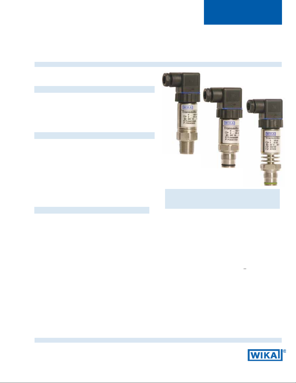
Description
WIKA S-10 and S-11 pressure transmitters are precision
engineered to t most industrial pressure measurement
applications. The compact, rugged design makes these
instruments suitable for applications including hydraulics and
pneumatics, vacuum, test equipment, liquid level measurement, press
control, compressor control, pump protection and
numerous other processing and control operations. A wide range
of electrical connection and process connection options are available to meet almost any requirement.
Rugged construction
The S-10 features an all-welded stainless steel measuring cell for
improved media compatibility. There are no internal soft sealing
materials that may react with the media or deteriorate over time.
The compact case is also made of stainless steel and is available
with environmental protection ratings up to NEMA 6P / IP 68.
Left: S-10 with NPT process connection
Center: S-11 with ush diaphragm process connection
Right: S-11 with ush diaphragm process connection and
integral cooling element
The S-11 transmitter features a ush diaphragm process
connection. The S-11 is specically designed for the
measurement of viscous uids or media containing solids
that may clog a NPT process connection. Flush diaphragm
pressure transmitters are available in pressure ranges
from 50 InWC to 8,000 psi. For high temperature media, an
integral cooling element is available on the S-11. This option
increases the maximum media temperature to 300
Each instrument undergoes extensive quality control testing
and calibration to achieve an accuracy of < 0.25% full scale.
The printed circuit boards use state-of-the-art surface mount
technology and are potted in silicone gel for protection
against mechanical shock, vibration and moisture. Each is
individually temperature compensated to assure accuracy
and long-term stability even when exposed to severe
ambient temperature variations.
O
F.
Datasheet S-10, S-11 1/2011
Page 1 of 4
R
Page 2

Specications Type S-10 / S-11
Pressure range 50 InWC 5 psi 10 psi 25 psi 30 psi 60 psi 100 psi 160 psi 200 psi
Maximum pressure* 14 psi 29 psi 58 psi 145 psi 145 psi 240 psi 500 psi 1,160 psi 1,160 psi
Burst pressure** 29 psi 35 psi 69 psi 170 psi 170 psi 290 psi 600 psi 1,390 psi 1,390 psi
Pressure range 300 psi 500 psi 1,000 psi 2,000 psi 3,000 psi 5,000 psi 8,000 psi 10,000 psi
Maximum pressure* 1,160 psi 1,160 psi 1,740 psi 4,600 psi 7,200 psi 11,600 psi 17,400 psi 17,400 psi 21,750 psi
Burst pressure** 1,390 psi 5,800 psi 7,970 psi 14,500 psi 17,400 psi 24,650 psi 34,800 psi 34,800 psi
{vacuum, gauge pressure, compound ranges, and absolute pressure references are available}
1)
Ranges only available with Model S-10
2)
For Model S-11 the burst pressure is limited to 21,000psi unless the pressure seal is accomplished by using the sealing ring underneath the hex.
*Pressure applied up to the maximum rating will cause no permanent change in specications but may lead to zero and span shifts
**Exceeding the burst pressure may result in destruction of the transmitter and possible loss of media
Materials
Wetted parts
Model S-10
Model S-11
Case
Internal transmission uid
Power supply U
Signal output and R
B
maximum load R
4)
3)
O-ring made of Viton or EPDM for Model S-11 with integral cooling element.
4)
Not available with Model S-10 in pressure ranges >300 psi.
5)
Media temperature for oxygen version: -4 ... +140 °F (-20....+60°C). Oxygen version is
6)
A
not available in vacuum and absolute pressure ranges or with S-11 > 500 psi
UB in DC V 10 < UB 30 (14 ... 30 with signal output 0 ... 10 V)
in Ohm 4 ... 20 mA, 2-wire RA < (UB - 10 V) / 0.02 A
A
Adjustability zero/span % ± 10 using potentiometers inside the instrument
Response time (10 ... 90 %) ms
(other materials see WIKA diaphragm seal program)
Stainless steel
Stainless steel
O-ring: NBR
Stainless steel
Synthetic oil {Halocarbon® oil for oxygen applications}
3)
{Viton® or EPDM}
5)
{Listed by FDA for food applications}}
≤
0 ... 20 mA, 3-wire RA < (UB - 3 V) / 0.02 A
{0 ... 5 V, 3-wire} R
{0 ... 10 V, 3-wire} R
> 5000
A
> 10,000 {other signal outputs available}
A
< 1 (< 10 ms at media temperatures below –22°F (-30°C) for ranges < 300 psi
or with ush diaphragm process connection)
Isolation voltage DC V 500
Accuracy
7)
6)
NEC Class 02 power supply (low voltage and low current max. 100 VA even under fault conditions)
% of span ≤ 0.25 {0.125}
% of span ≤ 0.5 {0.25}
7)
Including linearity, hysteresis and repeatability.
Limit point calibration performed in vertical mounting position with pressure connection facing down.
8)
Improved accuracy is available for pressure ranges > 100 InWC
8)
(BFSL)
8)
(limit point calibration)
Non-repeatability % of span ≤ 0.05
1-year stability % of span ≤ 0.2 (at reference conditions)
Permissible temperature of
Medium
Ambient
Storage
Compensated temperature range
9)
9)
9)
9)
Also complies with EN 50178, Tab. 7, Type C, Class 4KH Operation, 1K4 Storage, 1K3 Transport
-22 ... +212 °F {-40 ... +257 °F} -30 ... +100 °C {-40 ... +125 °C}
S-11 with cooling element: -4 ... +302 °F S-11 with cooling element: -20 ... +150 °C
-4 ... +176 °F -20 ... +80 °C
S-11 with cooling element: -4 ... +176 °F S-11 with cooling element: -20 ... +80 °C
-40 ... +212 °F -40 ... +100 °C
S-11 with cooling element: -4 ... +212°F S-11 with cooling element: -20 ... +100 °C
32 ... +176 °F 0 ... +80 °C
Temperature coecients (TC) within
compensated temp range:
Mean TC of zero
Mean TC of range
% of span ≤ 0.2 / 10 K (< 0.4 for pressure range < 100 InWC)
% of span ≤ 0.2 / 10 K
CE - conformity
Pressure equipment directive
EMC directive
97/23/EC
2004/108/EEC, EN 61 326 Emission Group (Group 1, Class B) and
Immunity )industrial locations
Shock resistance g 1000 according to IEC 60068-2-27 (mechanical shock)
Vibration resistance g 20 according to IEC 60068-2-6 (vibration under resonance)
Wiring protection Protected against reverse polarity, overvoltage and short circuit
Weight lb Approx. 0.4
1
15,000 psi
43,500 psi
1
{ } Items in curved brackets { } are optional extras for additional price.
Page 2 of 4 Datasheet S-10, S-11 · 1/2011
Page 3

Dimensions in inches(mm)
Electrical connections
L-connector, DIN EN
175301-803, Form A
(DIN 43 650) for conductor
cross section up to max.
1.5 mm² , conductor outer
diameter 0.3“ (6-8 mm),
NEMA 5 / IP 65
Order code: A4
1.89”(48mm)
1.14”(20mm)
Circular connector
M 12x1, 5 pin,
NEMA 4 / IP 67
Order code: M5
)see note
*
1.69”(43mm)
Cable with free ends
conductor cross section up
to max. 0.5 mm² /
AWG 20 with end splices,
conductor outer diameter
6.8 mm, NEMA 4 / IP 67
Order code: DL
Cable with free ends, adjustable
zero and span
conductor cross section up to max.
0.5 mm² / AWG 20 with end splices,
conductor outer diameter 6.8 mm,
NEMA 6 P / IP 68
Order code: XM
Case
1.79”(45.5mm)
1.06”(27mm)
S-10 pressure connections (others available)
1/2 NPT male
Order code: ND
.75”
(19mm)
1.08”(27.5mm)
1/2NPT
1/4 NPT male
Order code: NB
.51”(13mm)
.85”(21.5mm)
S-11 ush diaphragm pressure connections
G 1 B
with or without cooling element
50 InWC to 25 psi
Order code: 85
G 1/2 B
with or without cooling element
30 psi to 8000 psi
Order code: 86
1.12”(28.5mm)
.79”(20mm)
0.71”(18mm)
G1/2B male
Order code: GD
.12”(3mm)
.12”(3mm)
0.91”(23mm)
1.52”(38.5mm)
1.06”(27mm)
G1/4B male
Order code: GB
.24”
(6mm)
.85”(21.5mm)
O
.08”(2mm)
.08”(2mm)
.51”(13mm)
G1B according to EHEDG
**)
ø.20”
(5mm)
ø.37”
(9.5mm)
with cooling element , up to 302°F (150°C)
100 InWC to 250 psi
Order code: 84
1.79”(45.5mm)
1.26”(31.9mm)
.39”(10mm)
.80”(20.5mm)
) Mating connector not included
*
Sealing ring
29,7x35,7x2,0
O-ring 26x2
1.79”(45.5mm)
1.22”(30.9mm)
.81”(20.5mm)
.39”(10mm)
Sealing ring
18,5x23,9x1,5
O-ring 15x2
Sealing ring
29,7x35,7x2,0
1.98”(50.5mm)
.98”(25mm)
** European Hygenic Equipment Design Group
O-ring
21,82 x 3,53
Page 3 of 4Datasheet S-10, S-11 · 1/2011
Page 4
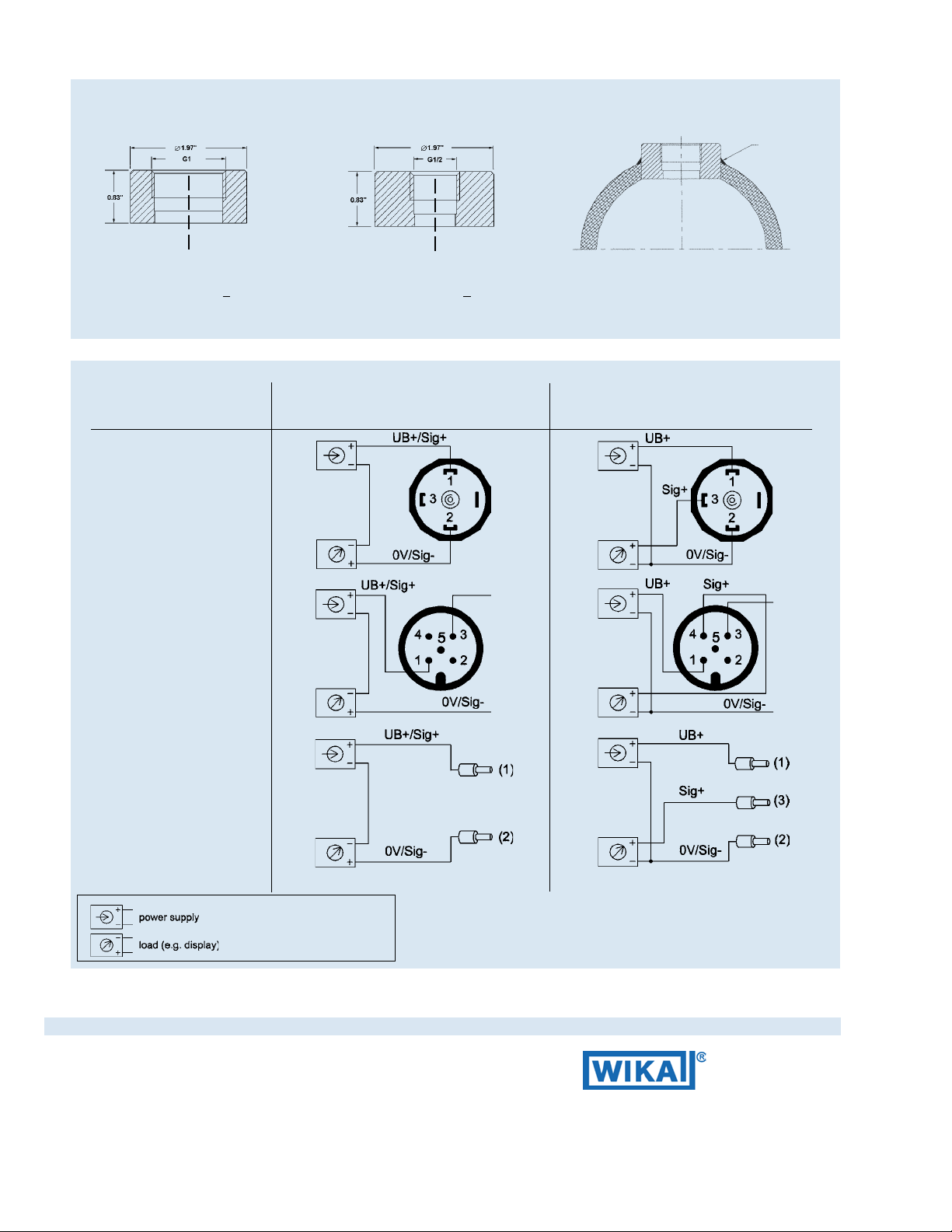
Matching P-1 weld insert adapters for S-11 pressure transmitters
weld
P-1 G1 weld insert adapter
Part # 1206974
for pressure ranges < 30 psi
Wiring
L-Connector,
DIN EN 175301-803, Form A
(DIN 43 650)
M12x1 Circular connector
5 pin
2-wire system
P-1 G1/2 weld insert adapter
Part # 1097008
for pressure ranges > 50 psi
Cross section view of P-1
adapter installed in pipe.
3-wire system
Vented cable with free ends
Legend:
Sig+ output signal positive
UB+ power supply positive
0V power supply negative
Sig - output signal negative
brown
green
brown
white
green
Datasheet S-10, S-11 · 1/2011Page 4 of 4
WIKA Instrument Corporation
1000 Wiegand Boulevard
Lawrenceville, Georgia 30043-5868
Tel: 770-513-8200 Fax: 77-338-5118
wika.com e-mail: info@wika.com
Page 4 of 4WIKA Data Sheet PE 81.01 · 02/2004
 Loading...