

Page 1
DE
EN
Operating instructions
Betriebsanleitung
Mode d‘emploi
Manual de instrucciones
ES
FR
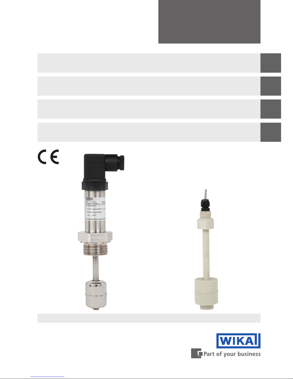
Level sensor with reed measuring chain
Models RLT-1000, RLT-2000, RLT-3000
Niveau-Messwertgeber mit Reed-Messkette
Typen RLT-1000, RLT-2000, RLT-3000
Capteur de niveau avec chaîne de mesure Reed
Types RLT-1000, RLT-2000, RLT-3000
Transmisores de nivel con cadena de medición Reed
Modelos RLT-1000, RLT-2000, RLT-3000
Model RLT-1000 Model RLT-2000
Page 2

2
14235428.01 07/2018 EN/DE/FR/ES
WIKA operating instructions models RLT
DE
EN
ES
FR
Operating instructions models RLT-1000,
RLT-2000, RLT-3000 Page 3 - 22
Betriebsanleitung Typen RLT-1000, RLT-2000,
RLT-3000 Seite 23 - 42
Mode d‘emploi types RLT-1000, RLT-2000,
RLT-3000 Page 43 - 62
Manual de instrucciones modelos RLT-1000,
RLT-2000, RLT-3000 Página 63 - 81
© 07/2018 WIKA Alexander Wiegand SE & Co. KG
All rights reserved. / Alle Rechte vorbehalten.
WIKA® is a registered trademark in various countries.
WIKA® ist eine geschützte Marke in verschiedenen Ländern.
Prior to starting any work, read the operating instructions!
Keep for later use!
Vor Beginn aller Arbeiten Betriebsanleitung lesen!
Zum späteren Gebrauch aufbewahren!
Lire le mode d‘emploi avant de commencer toute opération !
A conserver pour une utilisation ultérieure !
¡Leer el manual de instrucciones antes de comenzar cualquier trabajo!
¡Guardar el manual para una eventual consulta!
Page 3

EN
WIKA operating instructions models RLT
14235428.01 07/2018 EN/DE/FR/ES
3
Contents
Contents
Declarations of conformity can be found online at www.wika.com.
1. General information 4
2. Design and function 5
3. Safety 6
4. Transport, packaging and storage 11
5. Commissioning, operation 11
6. Faults 15
7. Maintenance and cleaning 16
8. Dismounting, return and disposal 17
9. Specications 18
Page 4

EN
14235428.01 07/2018 EN/DE/FR/ES
4
WIKA operating instructions models RLT
1. General information
■
The level sensors described in the operating instructions have been
designed and manufactured using state-of-the-art technology. All
components are subject to stringent quality and environmental
criteria during production. Our management systems are certied to
ISO 9001 and ISO 14001.
■
These operating instructions contain important information on
handling the instrument. Working safely requires that all safety
instructions and work instructions are observed.
■
Observe the relevant local accident prevention regulations and
general safety regulations for the instrument's range of use.
■
The operating instructions are part of the product and must be kept
in the immediate vicinity of the instrument and readily accessible to
skilled personnel at any time. Pass the operating instructions onto the
next user or owner of the instrument.
■
Skilled personnel must have carefully read and understood the
operating instructions prior to beginning any work.
■
The general terms and conditions contained in the sales
documentation shall apply.
■
Subject to technical modications.
■
Further information:
- Internet address: www.wika.de / www.wika.com
- Relevant data sheet: LM 50.01 (model RLT-2000)
LM 50.02 (model RLT-1000)
LM 50.05 (model RLT-3000)
- Application consultant: Tel.: +49 9372 132-0
Fax: +49 9372 132-406
info@wika.de
1. General information
Page 5

EN
WIKA operating instructions models RLT
14235428.01 07/2018 EN/DE/FR/ES
5
2.2 Scope of delivery
■
Level sensor
■
Operating instructions
Cross-check scope of delivery with delivery note.
2. Design and function
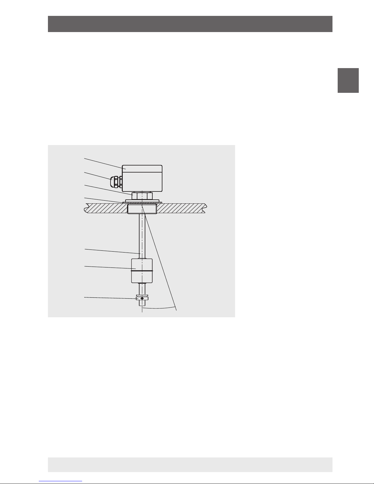
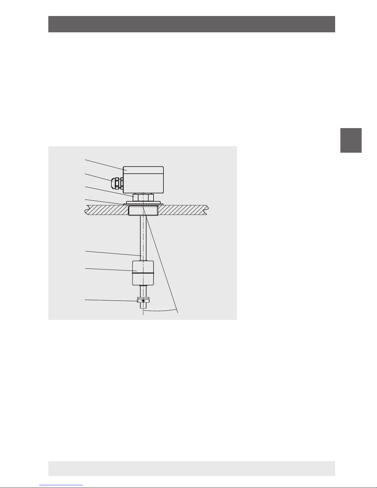
2.1 Functional description
Level sensors work on the oat principle with magnetic transmission.
A permanent magnet built into the oat triggers, with its magnetic
eld, the resistance measuring chain built into the guide tube .
The entire assembly corresponds to a 3-wire potentiometer circuit.
The oat changes its height with the level of the medium it is
monitoring. The measured resistance signal is proportional to the level.
The measurement voltage is very nely stepped due to the contact
separation of the resistance measuring chain and is thus virtually
continuous.
≤ 30°
Connection housing
Cable gland
Spanner ats for screwing in
Sealing
Guide tube
Float
Float stop
2. Design and function
Page 6
EN
14235428.01 07/2018 EN/DE/FR/ES
6
WIKA operating instructions models RLT
3. Safety
3.1 Explanation of symbols
DANGER!
... indicates a directly dangerous situation resulting in
serious injury or death, if not avoided.
WARNING!
... indicates a potentially dangerous situation that can result
in serious injury or death, if not avoided.
CAUTION!
... indicates a potentially dangerous situation that can result
in light injuries or damage to property or the environment, if
not avoided.
Information
... points out useful tips, recommendations and information
for ecient and trouble-free operation.
3.2 Intended use
Level sensors are used exclusively for monitoring the levels of liquid
media. The scope of application is dened by the technical performance
limits and materials.
■
The liquids must not have any large contamination or coarse particles
and must not have a tendency to crystallise. Ensure that the wetted
materials of the level sensor are suciently resistant to the medium
being monitored. Not suitable for dispersions, abrasive liquids, highly
viscous media and colours.
3. Safety
Page 7

EN
WIKA operating instructions models RLT
14235428.01 07/2018 EN/DE/FR/ES
7
■
This instrument is not permitted to be used in hazardous areas!
■
Do not operate the instrument in the direct vicinity of ferromagnetic
environments (min. distance 100 mm).
■
Do not operate the instrument in the immediate vicinity of strong
electromagnetic elds or in the immediate vicinity of equipment that
can be aected by magnetic elds (min. clearance 1 m).
■
The level sensors must not be exposed to heavy mechanical strain
(impact, bending, vibration).
■
The technical specications contained in these operating instructions
must be observed. Improper handling or operation of the instrument
outside of its technical specications requires the instrument to be
taken out of service immediately and inspected by an authorised
WIKA service engineer.
The instrument has been designed and built solely for the intended use
described here, and may only be used accordingly.
The manufacturer shall not be liable for claims of any type based on
operation contrary to the intended use.
DANGER!
Work on containers involves the danger of intoxication and
suocation. No work is allowed to be carried out unless by
taking suitable personal protective measures (e.g. respiratory
protection apparatus, protective outt etc.).
3. Safety
Page 8

EN
14235428.01 07/2018 EN/DE/FR/ES
8
WIKA operating instructions models RLT
3.3 Improper use
Improper use is dened as any application that exceeds the technical
performance limits or is not compatible with the materials.
WARNING!
Injuries through improper use
Improper use of the instrument can lead to hazardous
situations and injuries.
▶
Refrain from unauthorised modifications to the instrument.
▶
Do not use the instrument within hazardous areas.
Any use beyond or dierent to the intended use is considered as
improper use.
Do not use this instrument in safety or emergency stop devices.
3.4 Responsibility of the operator
The instrument is used in the industrial sector. The operator is therefore
responsible for legal obligations regarding safety at work.
The safety instructions within these operating instructions, as well as the
safety, accident prevention and environmental protection regulations for
the application area must be maintained.
To ensure safe working on the instrument, the operating company must
ensure
■
that suitable rst-aid equipment is available and aid is provided
whenever required.
■
that the operating personnel are regularly instructed in all topics
regarding work safety, rst aid and environmental protection
and know the operating instructions and in particular, the safety
instructions contained therein.
■
that the instrument is suitable for the particular application in
accordance with its intended use.
■
that following testing, improper use of the instrument is excluded.
3. Safety
Page 9

EN
WIKA operating instructions models RLT
14235428.01 07/2018 EN/DE/FR/ES
9
3.5 Personnelqualication
WARNING!
Riskofinjuryshouldqualicationbeinsucient
Improper handling can result in considerable injury and
damage to equipment.
▶
The activities described in these operating instructions
may only be carried out by skilled personnel who have the
qualifications described below.
Skilled personnel
Skilled personnel, authorised by the operator, are understood to
be personnel who, based on their technical training, knowledge
of measurement and control technology and on their experience
and knowledge of country-specic regulations, current standards
and directives, are capable of carrying out the work described and
independently recognising potential hazards.
3.6 Personal protective equipment
The personal protective equipment is designed to protect the skilled
personnel from hazards that could impair their safety or health during
work. When carrying out the various tasks on and with the instrument, the
skilled personnel must wear personal protective equipment.
Follow the instructions displayed in the work area regarding
personal protective equipment!
The requisite personal protective equipment must be provided by the
operating company.
3. Safety
Page 10

EN
14235428.01 07/2018 EN/DE/FR/ES
10
WIKA operating instructions models RLT
3.7 Labelling, safety marks
Product label (example)
3. Safety
Model
P# product number
S# serial number
Electrical connection
Before mounting and commissioning the instrument, ensure
you read the operating instructions!
Page 11

EN
WIKA operating instructions models RLT
14235428.01 07/2018 EN/DE/FR/ES
11
4. Transport, packaging and storage
4.1 Transport
Check the level sensor for any damage that may have been caused by
transport. Obvious damage must be reported immediately.
CAUTION!
With improper transport, a high level of damage to property
can occur.
▶
Observe the symbols on the packaging.
▶
Handle packed goods with care.
4.2 Packaging and storage
Do not remove packaging until just before commissioning.
Permissible conditions at the place of storage:
Storage temperature: -30 … +80 °C (-22 … +176 °F)
5. Commissioning, operation
■
Observe all instructions given on the shipment packaging for
removing the transportation safety devices.
■
Remove the level sensor carefully from the packaging!
■
When unpacking, check all components for any external damage.
5.1 Functional check
Prior to installation, a functional check of the level sensor can be
carried out with a resistance measuring instrument or a multimeter (for
instruments with 4 ... 20 mA output signal) and manual movement of the
oat.
4. Transport ... / 5. Commissioning, operation
Page 12

EN
14235428.01 07/2018 EN/DE/FR/ES
12
WIKA operating instructions models RLT
The following table describes the 3-wire resistance measurement and
the expected measured values for the movement of the oat, starting
from the oat stop in the direction of the tank opening.
Resistance measurement
of the wire colours
Measured value
BN―GN(R1)
Brown ― green
Resistance value rises proportionally with the
position of the oat.
WH―BN(R2)
White ― brown
Resistance value drops in inverse proportion
to the position of the oat.
GN―WH(Ri)
Green ― white
Overall resistance of the measuring chain
remains almost constant, irrespective of the
position of the oat
WARNING!
Ensure that the functional check does not start any
unintended processes.
5.2 Mounting preparation
Ensure that the sealing faces of the vessel or level sensor are clean and
do not show any mechanical damage.
5.3 Mounting
■
Observe the torque values of screws specied in pipetting work.
■
In the selection of the mounting material (sealings, screws, washers
and nuts), take the process conditions into account. The suitability
of the sealing must be specied with regard to the medium and
its vapours. In addition, ensure it has corresponding corrosion
resistance.
■
The guide tube should not be inclined more than a maximum of
30° to the vertical.
■
Mount the level sensor correctly for the design of the process
connection.
5. Commissioning, operation
Page 13
≤ 30°
EN
WIKA operating instructions models RLT
14235428.01 07/2018 EN/DE/FR/ES
13
■
If the opening of the process connection is too small for the oat, the
oat must be removed before mounting.
- Before removal, mark the position of the oat stop with a
waterproof pen
- Mark the mounting position of the oat (e.g. “Up”)
- After the level sensor has been mounted, the oat should be
re-attached within the inside of the tank (pay attention to the
mounting position!).
- Secure the oat stop again at the marked point.
5. Commissioning, operation
Page 14

EN
14235428.01 07/2018 EN/DE/FR/ES
14
WIKA operating instructions models RLT
5.4 Electrical connection
■
The electrical connection must only be made by qualied skilled
personnel.
■
Wire the level sensor in accordance with the connection diagram of
the electrical output (see product label). The connection terminals are
appropriately marked.
Electrical output Connection diagram
3-wire potentiometer
circuit
4 ... 20 mA
R
I
A
4 ... 20 mA
+
–
DC 12 ... 32 V
■
Seal the cable bushing at the connection housing (see
illustration in chapter 5.3 “Mounting”).
WARNING!
Malfunctions through voltage spikes due to running cables
together with mains connection leads or due to large cable
lengths.
This can lead to a malfunction in the plant and thus lead to
injury to personnel or damage to equipment.
▶
Use shielded connection leads.
▶
Ground connection leads at one end.
Always observe the mounting and operating instructions of accessories
when commissioning them.
GN
BN
WH
5. Commissioning, operation
Page 15

EN
WIKA operating instructions models RLT
14235428.01 07/2018 EN/DE/FR/ES
15
6. Faults
The following table contains the most frequent causes of
faults and the necessary countermeasures.
Faults Causes Measures
Level sensor cannot
be mounted at the
planned place on the
vessel
Process connection of
the level sensor does
not match the process
connection of the vessel
Modication of the vessel
Process connection at
the vessel defective
Rework the thread or replace
the screwed coupling
No signal, non-linear
orundenedsignals
Electrical connection
incorrect
See chapter 5.4 “Electrical
connection”. Check
assignment with the aid of the
connection diagram.
Measuring chain or
4 ... 20 mA evaluation
electronics defective
Return to the manufacturer
PLC evaluation
defective
Functional check of the
level sensor with resistance
measuring instrument/
multimeter
Analogue transmitter
shows signal < 4 mA
or > 25 mA
Cable break or
measuring chain
damaged
Functional check of the level
sensor, replacement as
required
CAUTION!
Physical injuries and damage to property and the
environment
If faults cannot be eliminated by means of the listed
measures, the instrument must be taken out of operation
immediately.
▶
Ensure that there is no longer any pressure present and
protect against being put into operation accidentally.
▶
Contact the manufacturer.
▶
If a return is needed, please follow the instructions given
in chapter 8.2 “Return”.
6. Faults
Page 16
EN
14235428.01 07/2018 EN/DE/FR/ES
16
WIKA operating instructions models RLT
7. Maintenance and cleaning
7.1 Maintenance
When used properly, the level sensors work maintenance-free. They
must be subjected to visual inspection within the context of regular
maintenance, however, and included in the vessel pressure test.
DANGER!
Work on containers involves the danger of intoxication and
suocation. No work is allowed to be carried out unless by
taking suitable personal protective measures (e.g. respiratory
protection apparatus, protective outt etc.).
Repairs must only be carried out by the manufacturer.
Perfect functioning of the level sensors can only be
guaranteed when original accessories and spare parts are
used.
7.2 Cleaning
CAUTION!
Physical injuries and damage to property and the
environment
Improper cleaning may lead to physical injuries, damage
to property and the environment and to damage to the
instrument. Residual media in the dismounted instrument
can result in a risk to persons, the environment and
equipment.
▶
Rinse or clean the dismounted instrument.
▶
Sufficient precautionary measures must be taken.
▶
Do not use any aggressive cleaning agents.
▶
Do not use any hard or pointed objects for cleaning.
1. Prior to cleaning, properly disconnect the instrument from the
process and the power supply.
2. Clean the instrument carefully with a moist cloth.
3. Electrical connections must not come into contact with moisture!
7. Maintenance and cleaning
Page 17

EN
WIKA operating instructions models RLT
14235428.01 07/2018 EN/DE/FR/ES
17
8. Dismounting, return and disposal
WARNING!
Physical injuries and damage to property and the
environment through residual media
Residual media in the dismounted instrument can result in
a risk to persons, the environment and equipment.
▶
Wash or clean the dismounted instrument, in order to
protect persons and the environment from exposure to
residual media.
8.1 Dismounting
Only disconnect the measuring instrument once the system has been
depressurised and the power disconnected!
8.2 Return
Wash or clean the dismounted level sensor before returning it, in order to
protect personnel and the environment from exposure to residual media.
Information on returns can be found under the heading
“Service” on our local website.
8.3 Disposal
Incorrect disposal can put the environment at risk.
Dispose of instrument components and packaging materials in an
environmentally compatible way and in accordance with the country-
specic waste disposal regulations.
8. Dismounting, return and disposal
Page 18

EN
14235428.01 07/2018 EN/DE/FR/ES
18
WIKA operating instructions models RLT
9. Specications
■
Model RLT-1000
Specications
Output signal
■
Variable resistance
The overall resistance of the reed chain is
approx. 1 ... 10 kΩ, depending on the measuring
range
Max. voltage < DC 40 V
■
Current output, 4 ... 20 mA, 2-wire
Power supply: DC 12 ... 32 V
Load in Ω: ≤ (power supply - 12 V) / 0.02 A
Accuracy, resolution
■
12 mm
■
10 mm
■
6 mm
■
3 mm
Permissible temperatures
■
Medium
■
Ambient
■
Storage
-30 … +80 °C (-22 … +176 °F)
Option: -30 … +120 °C (-22 … +248 °F)
1)
-30 … +80 °C (-22 … +176 °F)
-30 … +80 °C (-22 … +176 °F)
1) Not with cable material: PVC, PUR; not with oat outer diameter ∅ D = 30 mm; not with connection housing
58 x 64 x 36 mm
9.Specications
Page 19

EN
WIKA operating instructions models RLT
14235428.01 07/2018 EN/DE/FR/ES
19
9.Specications
■
Model RLT-2000
Specications
Output signal
■
Variable resistance
The overall resistance of the reed chain is
approx. 1 ... 10 kΩ, depending on the measuring
range
Max. voltage < DC 40 V
■
Current output, 4 ... 20 mA, 2-wire
Power supply: DC 12 ... 32 V
Load in Ω: ≤ (power supply - 12 V) / 0.02 A
Accuracy, resolution
■
12 mm
■
10 mm
■
6 mm
■
3 mm
Permissible temperatures
■
Medium
■
Ambient
■
Storage
PP: -10 … +80 °C (14 … 176 °F)
PVDF (option): -10 … +80 °C (14 … 176 °F)
Option: -30 … +120 °C (-22 … +248 °F)
PP: -10 … +80 °C (14 … 176 °F)
PVDF (option): -30 … +80 °C (-22 … +176 °F)
PP: -10 … +80 °C (14 … 176 °F)
PVDF (option): -30 … +80 °C (-22 … +176 °F)
Page 20

EN
14235428.01 07/2018 EN/DE/FR/ES
20
WIKA operating instructions models RLT
■
Model RLT-3000
Specications Level Temperature
Output signal
■
Current output,
4 ... 20 mA, 2-wire
Power supply:
DC 12 ... 32 V
Load in Ω:
≤ (power supply
- 12 V) / 0.02 A
■
Pt100, 2-wire
■
Pt1000, 2-wire
■
Current output,
4 ... 20 mA, 2-wire
Power supply:
DC 12 ... 32 V
Load in Ω:
≤ (power supply - 12 V)
/ 0.02 A
Accuracy
■
12 mm
■
10 mm
■
6 mm
■
3 mm
For reed-chain
technology, the
accuracy corresponds
to the resolution.
Class B per
DIN EN 60751,
for Pt100 / Pt1000
0.5 %, for current output
4 ... 20 mA
Permissible temperatures
■
Medium
■
Ambient
■
Storage
-30 … +100 °C (-22 … +212 °F)
-30 … +80 °C (-22 … +176 °F)
-30 … +80 °C (-22 … +176 °F)
9.Specications
Page 21

EN
WIKA operating instructions models RLT
14235428.01 07/2018 EN/DE/FR/ES
21
Overviewofoats
Form Outer
∅D
Height HOperating
pressure
Medium
temperature
Density Material
Cylinder 55 mm 65 mm ≤ 3 bar
(≤ 43.5 psi)
≤ 120 °C
(≤ 248 °F)
≥ 800 kg/m³ PVDF
Cylinder 55 mm 55 mm ≤ 3 bar
(≤ 43.5 psi)
≤ 80 °C
(≤ 176 °F)
≥ 500 kg/m³ PP
Cylinder 44 mm 44 mm ≤ 3 bar
(≤ 43.5 psi)
≤ 80 °C
(≤ 176 °F)
≥ 500 kg/m³ PP
Cylinder 44 mm 52 mm ≤ 16 bar
(≤ 232 psi)
≤ 120 °C
(≤ 248 °F)
≥ 750 kg/m³ 1.4571
(316Ti)
Cylinder 30 mm 36 mm ≤ 10 bar
(≤ 145 psi)
≤ 80 °C
(≤ 176 °F)
≥ 850 kg/m³ 1.4571
(316Ti)
Cylinder 25 mm 17 mm ≤ 16 bar
(≤ 232 psi)
≤ 80 °C
(≤ 176 °F)
≥ 500 kg/m³ Buna /
NBR
Sphere 52 mm 52 mm ≤ 40 bar
(≤ 580 psi)
≤ 120 °C
(≤ 248 °F)
≥ 750 kg/m³ 1.4571
(316Ti)
For further specifications see WIKA data sheets LM 50.01, LM 50.02,
LM 50.05 and the order documentation.
9.Specications
Page 22

EN
14235428.01 07/2018 EN/DE/FR/ES
22
WIKA operating instructions models RLT
Page 23

DE
WIKA Betriebsanleitung Typen RLT
14235428.01 07/2018 EN/DE/FR/ES
23
Inhalt
Inhalt
Konformitätserklärungen nden Sie online unter www.wika.de.
1. Allgemeines 24
2. Aufbau und Funktion 25
3. Sicherheit 26
4. Transport, Verpackung und Lagerung 31
5. Inbetriebnahme, Betrieb 31
6. Störungen 35
7. Wartung und Reinigung 36
8. Demontage, Rücksendung und Entsorgung 37
9. Technische Daten 38
Page 24

DE
14235428.01 07/2018 EN/DE/FR/ES
24
WIKA Betriebsanleitung Typen RLT
1. Allgemeines
■
Die in der Betriebsanleitung beschriebenen Niveau-Messwertgeber
werden nach dem aktuellen Stand der Technik konstruiert und gefertigt. Alle Komponenten unterliegen während der Fertigung strengen
Qualitäts- und Umweltkriterien. Unsere Managementsysteme sind
nach ISO 9001 und ISO 14001 zertiziert.
■
Diese Betriebsanleitung gibt wichtige Hinweise zum Umgang mit dem
Gerät. Voraussetzung für sicheres Arbeiten ist die Einhaltung aller
angegebenen Sicherheitshinweise und Handlungsanweisungen.
■
Die für den Einsatzbereich des Gerätes geltenden örtlichen Unfallverhütungsvorschriften und allgemeinen Sicherheitsbestimmungen
einhalten.
■
Die Betriebsanleitung ist Produktbestandteil und muss in unmittelbarer Nähe des Gerätes für das Fachpersonal jederzeit zugänglich
aufbewahrt werden. Betriebsanleitung an nachfolgende Benutzer
oder Besitzer des Gerätes weitergeben.
■
Das Fachpersonal muss die Betriebsanleitung vor Beginn aller Arbeiten sorgfältig durchgelesen und verstanden haben.
■
Es gelten die allgemeinen Geschäftsbedingungen in den Verkaufsunterlagen.
■
Technische Änderungen vorbehalten.
■
Weitere Informationen:
- Internet-Adresse: www.wika.de / www.wika.com
- Zugehöriges Datenblatt: LM 50.01 (Typ RLT-2000)
LM 50.02 (Typ RLT-1000)
LM 50.05 (Typ RLT-3000)
- Anwendungsberater: Tel.: +49 9372 132-0
Fax: +49 9372 132-406
info@wika.de
1. Allgemeines
Page 25

DE
WIKA Betriebsanleitung Typen RLT
14235428.01 07/2018 EN/DE/FR/ES
25
2.2 Lieferumfang
■
Niveau-Messwertgeber
■
Betriebsanleitung
Lieferumfang mit dem Lieferschein abgleichen.
2. Aufbau und Funktion
2.1 Funktionsbeschreibung
Niveau-Messwertgeber arbeiten nach dem Schwimmerprinzip mit
magnetischer Übertragung. Ein im Schwimmer eingebauter Permanentmagnet betätigt durch sein Magnetfeld die im Gleitrohr eingebaute Widerstandsmesskette. Der gesamte Aufbau entspricht einer
3-Leiter-Potentiometerschaltung. Der Schwimmer verändert seine
Höhenlage mit dem Flüssigkeitspegel des zu überwachenden Messstoffes. Das gemessene Widerstandssignal ist proportional zum Füllstand.
Die Messspannung ist bedingt durch das Kontaktraster der Widerstands-
messkette sehr feinstug und damit quasikontinuierlich.
≤ 30°
Anschlussgehäuse
Kabelverschraubung
Schlüsseläche zum
Einschrauben
Dichtung
Gleitrohr
Schwimmer
Schwimmeranschlag
2. Aufbau und Funktion
Page 26

DE
14235428.01 07/2018 EN/DE/FR/ES
26
WIKA Betriebsanleitung Typen RLT
3. Sicherheit
3.1 Symbolerklärung
GEFAHR!
... weist auf eine unmittelbar gefährliche Situation hin, die
zum Tod oder zu schweren Verletzungen führt, wenn sie
nicht gemieden wird.
WARNUNG!
... weist auf eine möglicherweise gefährliche Situation hin,
die zum Tod oder zu schweren Verletzungen führen kann,
wenn sie nicht gemieden wird.
VORSICHT!
... weist auf eine möglicherweise gefährliche Situation hin,
die zu geringfügigen oder leichten Verletzungen bzw. Sach-
und Umweltschäden führen kann, wenn sie nicht gemieden
wird.
Information
... hebt nützliche Tipps und Empfehlungen sowie Informatio-
nen für einen ezienten und störungsfreien Betrieb hervor.
3.2 Bestimmungsgemäße Verwendung
Niveau-Messwertgeber dienen ausschließlich der Füllstandsüberwa-
chung von üssigen Messstoen. Der Einsatzbereich ergibt sich aus den
technischen Leistungsgrenzen und Werkstoen.
■
Die Flüssigkeiten dürfen keine starken Verschmutzungen oder
Grobteile aufweisen und nicht zum Auskristallisieren neigen. Es ist
sicherzustellen, dass die messstoberührten Werkstoe des NiveauMesswertgebers gegen den zu überwachenden Messsto ausrei-
chend beständig sind. Nicht geeignet für Dispersionen, abrasive
Flüssigkeiten, hochviskose Medien und Farben.
3. Sicherheit
Page 27

DE
WIKA Betriebsanleitung Typen RLT
14235428.01 07/2018 EN/DE/FR/ES
27
■
Dieses Gerät ist nicht für den Einsatz in explosionsgefährdeten
Bereichen zugelassen!
■
Gerät nicht in unmittelbarer Nähe von ferromagnetischer Umgebung
(Abstand min. 100 mm) betreiben.
■
Gerät nicht in unmittelbarer Nähe von starken elektromagnetischen
Feldern bzw. in unmittelbarer Nähe von Einrichtungen betreiben, die
durch Magnetfelder beeinusst werden können (Abstand min. 1 m).
■
Die Niveau-Messwertgeber dürfen keinen starken mechanischen
Belastungen (Stoß, Verbiegen, Vibrationen) ausgesetzt werden.
■
Die technischen Spezikationen in dieser Betriebsanleitung sind
einzuhalten. Eine unsachgemäße Handhabung oder ein Betreiben
des Gerätes außerhalb der technischen Spezikationen macht die
sofortige Stilllegung und Überprüfung durch einen autorisierten
WIKA-Servicemitarbeiter erforderlich.
Das Gerät ist ausschließlich für den hier beschriebenen bestimmungsgemäßen Verwendungszweck konzipiert und konstruiert und darf nur
dementsprechend verwendet werden.
Ansprüche jeglicher Art aufgrund von nicht bestimmungsgemäßer
Verwendung sind ausgeschlossen.
GEFAHR!
Beim Arbeiten an Behältern besteht Vergiftungs- oder
Erstickungsgefahr. Arbeiten dürfen nur unter Anwendung
geeigneter Personenschutzmaßnahmen (z. B. Atemschutzgerät, Schutzkleidung o. Ä.) durchgeführt werden.
3. Sicherheit
Page 28

DE
14235428.01 07/2018 EN/DE/FR/ES
28
WIKA Betriebsanleitung Typen RLT
3.3 Fehlgebrauch
Als Fehlgebrauch gilt jede Verwendung, die die technischen Leistungs-
grenzen überschreitet oder mit den Werkstoen unverträglich ist.
WARNUNG!
Verletzungen durch Fehlgebrauch
Fehlgebrauch des Gerätes kann zu gefährlichen Situationen
und Verletzungen führen.
▶
Eigenmächtige Umbauten am Gerät unterlassen.
▶
Gerät nicht in explosionsgefährdeten Bereichen einsetzen.
Jede über die bestimmungsgemäße Verwendung hinausgehende oder
andersartige Benutzung gilt als Fehlgebrauch.
Dieses Gerät nicht in Sicherheits- oder in Not-Aus-Einrichtungen benutzen.
3.4 Verantwortung des Betreibers
Das Gerät wird im gewerblichen Bereich eingesetzt. Der Betreiber unter-
liegt daher den gesetzlichen Pichten zur Arbeitssicherheit.
Die Sicherheitshinweise dieser Betriebsanleitung, sowie die für den
Einsatzbereich des Gerätes gültigen Sicherheits-, Unfallverhütungs- und
Umweltschutzvorschriften einhalten.
Für ein sicheres Arbeiten am Gerät muss der Betreiber sicherstellen,
■
dass eine entsprechende Erste-Hilfe-Ausrüstung vorhanden ist und
bei Bedarf jederzeit Hilfe zur Stelle ist.
■
dass das Bedienpersonal regelmäßig in allen zutreenden Fragen
von Arbeitssicherheit, Erste Hilfe und Umweltschutz unterwiesen
wird, sowie die Betriebsanleitung und insbesondere die darin enthaltenen Sicherheitshinweise kennt.
■
dass das Gerät gemäß der bestimmungsgemäßen Verwendung für
den Anwendungsfall geeignet ist.
■
dass nach Prüfung ein Fehlgebrauch des Gerätes ausgeschlossen
ist.
3. Sicherheit
Page 29

DE
WIKA Betriebsanleitung Typen RLT
14235428.01 07/2018 EN/DE/FR/ES
29
3.5 Personalqualikation
WARNUNG!
VerletzungsgefahrbeiunzureichenderQualikation
Unsachgemäßer Umgang kann zu erheblichen Personen-
und Sachschäden führen.
▶
Die in dieser Betriebsanleitung beschriebenen Tätigkeiten nur durch Fachpersonal nachfolgend beschriebener
Qualifikation durchführen lassen.
Fachpersonal
Das vom Betreiber autorisierte Fachpersonal ist aufgrund seiner
fachlichen Ausbildung, seiner Kenntnisse der Mess- und Regelungstechnik und seiner Erfahrungen sowie Kenntnis der landesspezischen Vorschriften, geltenden Normen und Richtlinien in der Lage, die
beschriebenen Arbeiten auszuführen und mögliche Gefahren selbstständig zu erkennen.
3.6 Persönliche Schutzausrüstung
Die persönliche Schutzausrüstung dient dazu, das Fachpersonal gegen
Gefahren zu schützen, die dessen Sicherheit oder Gesundheit bei der
Arbeit beeinträchtigen könnten. Beim Ausführen der verschiedenen
Arbeiten an und mit dem Gerät muss das Fachpersonal persönliche
Schutzausrüstung tragen.
Im Arbeitsbereich angebrachte Hinweise zur persönlichen Schutzausrüstung befolgen!
Die erforderliche persönliche Schutzausrüstung muss vom Betreiber zur
Verfügung gestellt werden.
3. Sicherheit
Page 30

DE
14235428.01 07/2018 EN/DE/FR/ES
30
WIKA Betriebsanleitung Typen RLT
3.7 Beschilderung, Sicherheitskennzeichnungen
Typenschild (Beispiel)
3. Sicherheit
Typ
P# Erzeugnisnummer
S# Seriennummer
Elektrischer Anschluss
Vor Montage und Inbetriebnahme des Gerätes unbedingt die
Betriebsanleitung lesen!
Page 31

DE
WIKA Betriebsanleitung Typen RLT
14235428.01 07/2018 EN/DE/FR/ES
31
4. Transport, Verpackung und Lagerung
4.1 Transport
Niveau-Messwertgeber auf eventuell vorhandene Transportschäden
untersuchen. Oensichtliche Schäden unverzüglich mitteilen.
VORSICHT!
Bei unsachgemäßem Transport können Sachschäden in
erheblicher Höhe entstehen.
▶
Symbole auf der Verpackung beachten.
▶
Packstücke vorsichtig behandeln.
4.2 Verpackung und Lagerung
Verpackung erst unmittelbar vor der Inbetriebnahme entfernen.
Zulässige Bedingungen am Lagerort:
Lagertemperatur: -30 … +80 °C (-22 … +176 °F)
5. Inbetriebnahme, Betrieb
■
Alle auf der Versandverpackung angegebenen Hinweise zum Entfernen der Transportsicherungen beachten.
■
Den Niveau-Messwertgeber vorsichtig aus der Verpackung entnehmen!
■
Beim Auspacken alle Teile auf äußerliche Beschädigungen überprüfen.
5.1 Funktionsprüfung
Vor der Montage kann eine Funktionsprüfung des Niveau-Messwertgebers mit einem Widerstandsmessgerät bzw. Multimeter bei Geräten
mit 4 ... 20 mA-Ausgangssignal und manueller Schwimmerbewegung
erfolgen.
4. Transport ... / 5. Inbetriebnahme, Betrieb
Page 32

DE
14235428.01 07/2018 EN/DE/FR/ES
32
WIKA Betriebsanleitung Typen RLT
Die nachfolgende Tabelle beschreibt die 3-Leiter-Widerstandsmessung
und die erwarteten Messwerte bei der Bewegung des Schwimmers
beginnend vom Schwimmeranschlag in Richtung Tankönung.
Widerstandsmessung
der Aderfarben
Messwert
BN―GN(R1)
Braun ― Grün
Widerstandswert steigt proportional mit der Position
des Schwimmers an.
WH―BN(R2)
Weiß ― Braun
Widerstandswert sinkt umgekehrt proportional mit
der Position des Schwimmers.
GN―WH(Ri)
Grün ― Weiß
Gesamtwiderstand der Messkette bleibt unabhängig von der Schwimmerposition nahezu konstant
WARNUNG!
Sicherstellen, dass die Funktionsprüfung keine unbeabsichtigten Prozesse startet.
5.2 Montagevorbereitung
Sicherstellen, dass die Dichtächen des Behälters bzw. des Niveau-
Messwertgebers sauber sind und keine mechanische Beschädigung
aufweisen.
5.3 Montage
■
Die im Rohrleitungsbau vorgeschriebenen Drehmomentwerte der
Schrauben einhalten.
■
Bei der Auswahl des Montagematerials (Dichtungen, Schrauben,
Unterlegscheiben und Muttern) die Prozessbedingungen beachten.
Die Eignung der Dichtung muss hinsichtlich Messsto und dessen
Dämpfen gegeben sein. Zusätzlich ist auf entsprechende Korrosionsbeständigkeit zu achten.
■
Das Gleitrohr darf maximal 30° zur Vertikalen geneigt sein.
■
Niveau-Messwertgeber je nach Ausführung des Prozessanschlusses
fachgerecht montieren.
5. Inbetriebnahme, Betrieb
Page 33

≤ 30°
DE
WIKA Betriebsanleitung Typen RLT
14235428.01 07/2018 EN/DE/FR/ES
33
■
Ist die Önung des Prozessanschlusses zu klein für den Schwimmer,
muss der Schwimmer vor der Montage entfernt werden.
- Position des Schwimmeranschlages vor dem Abbauen mit einem
wasserfesten Stift markieren
- Einbaulage des Schwimmers kennzeichnen (z. B. „Oben“)
- Nach der Montage des Niveau-Messwertgebers ist der Schwimmer
im Inneren des Tanks wieder anzubauen (Einbaulage beachten!).
- Schwimmeranschlag an der markierten Stelle wieder befestigen.
5. Inbetriebnahme, Betrieb
Page 34

DE
14235428.01 07/2018 EN/DE/FR/ES
34
WIKA Betriebsanleitung Typen RLT
5.4 Elektrischer Anschluss
■
Der elektrische Anschluss darf nur durch qualiziertes Fachpersonal
erfolgen.
■
Niveau-Messwertgeber nach Anschlussschema des elektrischen
Ausgangs (siehe Typenschild) verdrahten. Die Anschlussklemmen
sind entsprechend gekennzeichnet.
Elektrischer Ausgang Anschlussschema
3-Leiter-Potentiometerschaltung
4 ... 20 mA
R
I
A
4 ... 20 mA
+
–
DC 12 ... 32 V
■
Die Kabeldurchführung am Anschlussgehäuse abdichten (siehe
Abbildung in Kapitel 5.3 „Montage“).
WARNUNG!
Fehlfunktionen bei gemeinsamer Verlegung mit Netzanschlussleitungen oder bei großen Leitungslängen durch
Spannungsspitzen.
Dies kann zu einer Fehlfunktion der Anlage und dadurch zu
Personen- oder Sachschäden führen.
▶
Abgeschirmte Anschlussleitungen verwenden.
▶
Anschlussleitungen einseitig erden.
Zur Inbetriebnahme von Zubehör unbedingt die jeweilige Montage- und
Betriebsanleitung beachten.
GN
BN
WH
5. Inbetriebnahme, Betrieb
Page 35

DE
WIKA Betriebsanleitung Typen RLT
14235428.01 07/2018 EN/DE/FR/ES
35
6. Störungen
In der folgenden Tabelle sind die häufigsten Fehlerursachen
und erforderliche Gegenmaßnahmen aufgeführt.
Störungen Ursachen Maßnahmen
Niveau-Messwertgeber lässt sich nicht
an der vorgesehenen
Stelle am Behälter
anbauen
Prozessanschluss des
Niveau-Messwertgebers
passt nicht zu dem
Prozessanschluss des
Behälters
Umbau des Behälters
Prozessanschluss am
Behälter defekt
Nacharbeiten des Gewindes oder Austauschen der
Befestigungsmue
Keine, nicht-lineare
oderundenierte
Signale
Elektrischer Anschluss
falsch
Siehe Kapitel 5.4
„Elektrischer Anschluss“.
Belegung mit Hilfe des Anschlussschemas prüfen.
Messkette oder 4 ... 20 mAAuswerteelektronik defekt
Rücksendung ans Werk
SPS-Auswertung defekt Funktionsprüfung des
Niveau-Messwertgebers
mit Widerstandsmessgerät/Multimeter
Analogmessumformer
zeigt Signal < 4 mA
oder > 25 mA
Kabelbruch oder Messkette beschädigt
Funktionsprüfung des
Niveau-Messwertgebers,
Austausch nach Bedarf
VORSICHT!
Körperverletzungen, Sach- und Umweltschäden
Können Störungen mit Hilfe der aufgeführten Maßnahmen
nicht beseitigt werden, Gerät unverzüglich außer Betrieb
setzen.
▶
Sicherstellen, dass kein Druck mehr anliegt und gegen
versehentliche Inbetriebnahme schützen.
▶
Kontakt mit dem Hersteller aufnehmen.
▶
Bei notwendiger Rücksendung die Hinweise unter Kapitel
8.2 „Rücksendung“ beachten.
6. Störungen
Page 36

DE
14235428.01 07/2018 EN/DE/FR/ES
36
WIKA Betriebsanleitung Typen RLT
7. Wartung und Reinigung
7.1 Wartung
Die Niveau-Messwertgeber arbeiten bei bestimmungsgemäßem
Gebrauch wartungsfrei. Sie sind jedoch im Rahmen der regelmäßigen
Wartung einer Sichtkontrolle zu unterziehen und in die Druckprüfung des
Behälters mit einzubeziehen.
GEFAHR!
Beim Arbeiten an Behältern besteht Vergiftungs- oder
Erstickungsgefahr. Arbeiten dürfen nur unter Anwendung
geeigneter Personenschutzmaßnahmen (z. B. Atemschutzgerät, Schutzkleidung o. Ä.) durchgeführt werden.
Reparaturen sind ausschließlich vom Hersteller durchzuführen.
Die Funktion der Niveau-Messwertgeber kann nur bei
Verwendung von Originalzubehör und Ersatzteilen gewährleistet werden.
7.2 Reinigung
VORSICHT!
Körperverletzungen, Sach- und Umweltschäden
Eine unsachgemäße Reinigung führt zu Körperverletzun-
gen, Sach- und Umweltschäden und zur Beschädigung des
Gerätes. Messstoffreste im ausgebauten Gerät können zur
Gefährdung von Personen, Umwelt und Einrichtung führen.
▶
Ausgebautes Gerät spülen bzw. säubern.
▶
Ausreichende Vorsichtsmaßnahmen sind zu ergreifen.
▶
Keine aggressiven Reinigungmittel verwenden.
▶
Keine harten und spitzen Gegenstände zur Reinigung
verwenden.
1. Vor der Reinigung das Gerät ordnungsgemäß vom Prozess und der
Stromversorgung trennen.
2. Das Gerät vorsichtig mit einem feuchten Tuch reinigen.
3. Elektrische Anschlüsse nicht mit Feuchtigkeit in Berührung bringen!
7. Wartung und Reinigung
Page 37

DE
WIKA Betriebsanleitung Typen RLT
14235428.01 07/2018 EN/DE/FR/ES
37
8. Demontage, Rücksendung und Entsorgung
WARNUNG!
Körperverletzungen, Sach- und Umweltschäden durch
Messstoreste
Messstoffreste im ausgebauten Gerät können zur Gefähr-
dung von Personen, Umwelt und Einrichtung führen.
▶
Ausgebautes Gerät spülen bzw. säubern, um Personen
und Umwelt vor Gefährdung durch anhaftende Messstoffreste zu schützen.
8.1 Demontage
Messgerät nur im drucklosen und spannungsfreiem Zustand demontieren!
8.2 Rücksendung
Ausgebauten Niveau-Messwertgeber vor der Rücksendung spülen bzw.
säubern, um Mitarbeiter und Umwelt vor Gefährdung durch anhaftende
Messstoreste zu schützen.
Hinweise zur Rücksendung benden sich in der Rubrik
„Service“ auf unserer lokalen Internetseite.
8.3 Entsorgung
Durch falsche Entsorgung können Gefahren für die Umwelt entstehen.
Gerätekomponenten und Verpackungsmaterialien entsprechend den
landesspezischen Abfallbehandlungs- und Entsorgungsvorschriften
umweltgerecht entsorgen.
8. Demontage, Rücksendung und Entsorgung
Page 38

DE
14235428.01 07/2018 EN/DE/FR/ES
38
WIKA Betriebsanleitung Typen RLT
9. Technische Daten
■
Typ RLT-1000
Technische Daten
Ausgangssignal
■
Veränderlicher Widerstand
Gesamtwiderstand der Reed-Kette beträgt je nach
Messbereich ca. 1 ... 10 kΩ
Max. Spannung < DC 40 V
■
Stromausgang, 4 ... 20 mA, 2-Leiter
Hilfsenergie: DC 12 ... 32 V
Bürde in Ω: ≤ (Hilfsenergie - 12 V) / 0,02 A
Genauigkeit,Auösung
■
12 mm
■
10 mm
■
6 mm
■
3 mm
Zulässige Temperaturen
■
Messsto
■
Umgebung
■
Lagerung
-30 … +80 °C (-22 … +176 °F)
Option: -30 … +120 °C (-22 … +248 °F)
1)
-30 … +80 °C (-22 … +176 °F)
-30 … +80 °C (-22 … +176 °F)
1) Nicht mit Kabelmaterial: PVC, PUR; nicht mit Schwimmer-Außendurchmesser ∅ D = 30 mm; nicht mit
Anschlussgehäuse 58 x 64 x 36 mm
9. Technische Daten
Page 39

DE
WIKA Betriebsanleitung Typen RLT
14235428.01 07/2018 EN/DE/FR/ES
39
9. Technische Daten
■
Typ RLT-2000
Technische Daten
Ausgangssignal
■
Veränderlicher Widerstand
Gesamtwiderstand der Reed-Kette beträgt je nach
Messbereich ca. 1 ... 10 kΩ
Max. Spannung < DC 40 V
■
Stromausgang, 4 ... 20 mA, 2-Leiter
Hilfsenergie: DC 12 ... 32 V
Bürde in Ω: ≤ (Hilfsenergie - 12 V) / 0,02 A
Genauigkeit,Auösung
■
12 mm
■
10 mm
■
6 mm
■
3 mm
Zulässige Temperaturen
■
Messsto
■
Umgebung
■
Lagerung
PP: -10 … +80 °C (14 … 176 °F)
PVDF (Option): -10 … +80 °C (14 … 176 °F)
Option: -30 … +120 °C (-22 … +248 °F)
PP: -10 … +80 °C (14 … 176 °F)
PVDF (Option): -30 … +80 °C (-22 … +176 °F)
PP: -10 … +80 °C (14 … 176 °F)
PVDF (Option): -30 … +80 °C (-22 … +176 °F)
Page 40

DE
14235428.01 07/2018 EN/DE/FR/ES
40
WIKA Betriebsanleitung Typen RLT
■
Typ RLT-3000
Technische Daten Füllstand Temperatur
Ausgangssignal
■
Stromausgang,
4 ... 20 mA, 2-Leiter
Hilfsenergie:
DC 12 ... 32 V
Bürde in Ω:
≤ (Hilfsenergie - 12 V) /
0,02 A
■
Pt100, 2-Leiter
■
Pt1000, 2-Leiter
■
Stromausgang,
4 ... 20 mA, 2-Leiter
Hilfsenergie:
DC 12 ... 32 V
Bürde in Ω:
≤ (Hilfsenergie
- 12 V) / 0,02 A
Genauigkeit
■
12 mm
■
10 mm
■
6 mm
■
3 mm
Für die Reed-Kettentechnik enstpricht die Genauig-
keit der Auösung.
Klasse B nach
DIN EN 60751, für
Pt100 / Pt1000
0,5 %, für Stromausgang 4 ... 20 mA
Zulässige Temperaturen
■
Messsto
■
Umgebung
■
Lagerung
-30 … +100 °C (-22 … +212 °F)
-30 … +80 °C (-22 … +176 °F)
-30 … +80 °C (-22 … +176 °F)
9. Technische Daten
Page 41

DE
WIKA Betriebsanleitung Typen RLT
14235428.01 07/2018 EN/DE/FR/ES
41
Übersicht Schwimmer
Form Außen-∅DHöhe HBetriebs-
druck
Messstotemperatur
Dichte Material
Zylinder 55 mm 65 mm ≤ 3 bar
(≤ 43,5 psi)
≤ 120 °C
(≤ 248 °F)
≥ 800 kg/m³ PVDF
Zylinder 55 mm 55 mm ≤ 3 bar
(≤ 43,5 psi)
≤ 80 °C
(≤ 176 °F)
≥ 500 kg/m³ PP
Zylinder 44 mm 44 mm ≤ 3 bar
(≤ 43,5 psi)
≤ 80 °C
(≤ 176 °F)
≥ 500 kg/m³ PP
Zylinder 44 mm 52 mm ≤ 16 bar
(≤ 232 psi)
≤ 120 °C
(≤ 248 °F)
≥ 750 kg/m³ 1.4571
(316Ti)
Zylinder 30 mm 36 mm ≤ 10 bar
(≤ 145 psi)
≤ 80 °C
(≤ 176 °F)
≥ 850 kg/m³ 1.4571
(316Ti)
Zylinder 25 mm 17 mm ≤ 16 bar
(≤ 232 psi)
≤ 80 °C
(≤ 176 °F)
≥ 500 kg/m³ Buna /
NBR
Kugel 52 mm 52 mm ≤ 40 bar
(≤ 580 psi)
≤ 120 °C
(≤ 248 °F)
≥ 750 kg/m³ 1.4571
(316Ti)
Weitere technische Daten siehe WIKA-Datenblätter LM 50.01,
LM 50.02, LM 50.05 und Bestellunterlagen.
9. Technische Daten
Page 42

DE
14235428.01 07/2018 EN/DE/FR/ES
42
WIKA Betriebsanleitung Typen RLT
Page 43

FR
WIKA mode d‘emploi types RLT
14235428.01 07/2018 EN/DE/FR/ES
43
Sommaire
Sommaire
Déclarations de conformité disponibles sur www.wika.fr.
1. Généralités 44
2. Conception et fonction 45
3. Sécurité 46
4. Transport, emballage et stockage 51
5. Mise en service, utilisation 51
6. Dysfonctionnements 55
7. Entretien et nettoyage 56
8. Démontage, retour et mise au rebut 57
9. Spécications 58
Page 44

FR
14235428.01 07/2018 EN/DE/FR/ES
44
WIKA mode d‘emploi types RLT
1. Généralités
■
Les capteurs de niveau décrits dans le mode d'emploi sont conçus
et fabriqués selon les dernières technologies en vigueur. Tous les
composants sont soumis à des exigences environnementales et de
qualité strictes durant la fabrication. Nos systèmes de gestion sont
certiés selon ISO 9001 et ISO 14001.
■
Ce mode d'emploi donne des indications importantes concernant
l'utilisation de l'instrument. Il est possible de travailler en toute
sécurité avec ce produit en respectant toutes les consignes de
sécurité et d'utilisation.
■
Respecter les prescriptions locales de prévention contre les
accidents et les prescriptions générales de sécurité en vigueur pour
le domaine d'application de l'instrument.
■
Le mode d'emploi fait partie de l'instrument et doit être conservé à
proximité immédiate de l'instrument et accessible à tout moment pour
le personnel qualié. Transmettre le mode d'emploi à l'utilisateur ou
propriétaire ultérieur de l'instrument.
■
Le personnel qualié doit, avant de commencer toute opération, avoir
lu soigneusement et compris le mode d'emploi.
■
Les conditions générales de vente mentionnées dans les documents
de vente s'appliquent.
■
Sous réserve de modications techniques.
■
Pour obtenir d'autres informations :
- Consulter notre site Internet : www.wika.fr
- Fiche technique correspondante : LM 50.01 (type RLT-2000)
LM 50.02 (type RLT-1000)
LM 50.05 (type RLT-3000)
- Conseiller applications : Tel.: 0 820 951010 (0,15 €/min)
+33 1 787049-46
Fax: 0 891 035891
(0,35 €/min)
info@wika.fr
1. Généralités
Page 45

FR
WIKA mode d‘emploi types RLT
14235428.01 07/2018 EN/DE/FR/ES
45
2.2 Détail de la livraison
■
Transmetteur de niveau à otteur
■
Mode d'emploi
Comparer le détail de la livraison avec le bordereau de livraison.
2. Conception et fonction
2.1 Description fonctionnelle
Les capteurs de niveau fonctionnent selon le principe du otteur avec
transmission magnétique. Un aimant permanent placé dans le otteur
déclenche, avec son champ magnétique, la chaîne de mesure de
résistance placée dans le tube de guidage . L'assemblage complet
correspond à un circuit de potentiomètre 3 ls. Le otteur change de
hauteur avec le niveau du uide qu'il surveille. Le signal de résistance
mesuré est proportionnel au niveau. La tension de mesure ainsi produite
évolue avec le pas de la chaîne de mesure de résistance et est quasicontinue.
≤ 30°
Boîtier de connexion
Presse-étoupe
Surfaces de clé pour vissage
Etanchéité
Tube guide
Flotteur
Butée de otteur
2. Conception et fonction
Page 46

FR
14235428.01 07/2018 EN/DE/FR/ES
46
WIKA mode d‘emploi types RLT
3. Sécurité
3.1 Explication des symboles
DANGER !
... indique une situation dangereuse pouvant entraîner la
mort ou des blessures graves si elle n'est pas évitée.
AVERTISSEMENT !
… indique une situation présentant des risques susceptibles
de provoquer la mort ou des blessures graves si elle n'est
pas évitée.
ATTENTION !
… indique une situation potentiellement dangereuse et
susceptible de provoquer de légères blessures ou des
dommages pour le matériel et pour l'environnement si elle
n'est pas évitée.
Information
... met en exergue les conseils et recommandations utiles
de même que les informations permettant d'assurer un
fonctionnement ecace et normal.
3.2 Utilisation conforme à l'usage prévu
Les capteurs de niveau sont utilisés exclusivement pour surveiller les
niveaux de uides liquides. Le domaine d'application est déni par les
limites techniques de performance et les matériaux.
■
Les liquides doivent être exempts de toute contamination importante
ou de particules en suspension grossières et ne doivent pas avoir
tendance à cristalliser. Assurez-vous que les matériaux en contact
avec le uide du capteur de niveau soient susamment résistants
au uide qui est contrôlé. Ne convient pas aux milieux dispersés,
liquides abrasifs, uides hautement visqueux.
3. Sécurité
Page 47

FR
WIKA mode d‘emploi types RLT
14235428.01 07/2018 EN/DE/FR/ES
47
■
Cet instrument n'est pas certié pour être utilisé en zones explosives !
■
Ne pas utiliser l'instrument à proximité directe d'environnements
ferromagnétiques (distance min. 100 mm).
■
Ne pas utiliser l'instrument à proximité immédiate de champs
électromagnétiques puissants ou d'appareils pouvant être perturbés
par des champs magnétiques (distance min. 1 m).
■
Les capteurs de niveau ne doivent pas être exposés à de fortes
contraintes mécaniques (impacts, exions, vibrations).
■
Les spécications techniques mentionnées dans ce mode d'emploi
doivent être respectées. En cas d'utilisation non conforme ou
de fonctionnement de l'instrument en dehors des spécications
techniques, un arrêt et contrôle doivent être immédiatement eectués
par un collaborateur autorisé du service de WIKA.
Ces instruments sont conçus et construits exclusivement pour une
utilisation conforme à l'usage prévu décrit ici, et ne doivent être utilisés
qu'à cet eet.
Aucune réclamation ne peut être recevable en cas d'utilisation non
conforme à l'usage prévu.
DANGER !
Le travail sur les conteneurs implique un danger
d'intoxication et de suocation. Aucun travail ne peut
être eectué, sauf en prenant des mesures de protection
personnelle appropriées (par exemple appareil de protection
respiratoire, tenue de protection etc.).
3. Sécurité
Page 48

FR
14235428.01 07/2018 EN/DE/FR/ES
48
WIKA mode d‘emploi types RLT
3.3 Utilisation inappropriée
On dénit un usage impropre comme étant toute application qui excède
les limites techniques de performance ou étant incompatible avec les
matériaux.
AVERTISSEMENT !
Blessures causées par une utilisation inappropriée
Une utilisation inappropriée peut conduire à des situations
dangereuses et à des blessures.
▶
S'abstenir de modifications non autorisées sur l'instrument.
▶
Ne pas utiliser l'instrument en zone explosive.
Toute utilisation diérente ou au-delà de l'utilisation prévue est
considérée comme inappropriée.
Ne pas utiliser cet instrument dans des dispositifs de sécurité ou d'arrêt
d'urgence.
3.4 Responsabilité de l'opérateur
L'instrument est prévu pour un usage dans le domaine industriel.
L'opérateur est de ce fait responsable des obligations légales en matière
de sécurité du travail.
Les instructions de sécurité de ce mode d'emploi comme les
réglementations liées à la sécurité, à la prévention des accidents et à la
protection de l'environnement pour le domaine d'application doivent être
respectées.
An de travailler en toute sécurité sur l'instrument, la société exploitante
doit s'assurer
■
qu'un équipement de premier secours adapté est disponible et que
les premiers soins peuvent être dispensés sur place à tout moment
en cas de besoin.
■
que le personnel de service soit formé à intervalles réguliers sur tous
les sujets concernant la sécurité du travail, les premiers secours et
la protection de l'environnement et qu'il connaît le mode d'emploi et
particulièrement les consignes de sécurité contenues dans celui-ci.
3. Sécurité
Page 49

FR
WIKA mode d‘emploi types RLT
14235428.01 07/2018 EN/DE/FR/ES
49
■
que l'instrument est adapté à l'application en respect de l'usage
prévu de l'instrument.
■
qu'à la suite des essais, une utilisation impropre de l'instrument est
exclue.
3.5 Qualicationdupersonnel
AVERTISSEMENT !
Dangerdeblessureencasdequalicationinsusante
Une utilisation non conforme peut entraîner d'importants
dommages corporels et matériels.
▶
Les opérations décrites dans ce mode d'emploi ne
doivent être effectuées que par un personnel ayant la
qualification décrite ci-après.
Personnelqualié
Le personnel qualié, autorisé par l'opérateur, est, en raison de sa
formation spécialisée, de ses connaissances dans le domaine de
l'instrumentation de mesure et de régulation et de son expérience,
de même que de sa connaissance des réglementations nationales et
des normes en vigueur, en mesure d'eectuer les travaux décrits et
d'identier de façon autonome les dangers potentiels.
3.6 Equipement de protection individuelle
L'équipement de protection individuelle sert à protéger le personnel
qualié contre les dangers pouvant entraver la sécurité et la santé de ce
dernier durant le travail. Le personnel qualié doit porter l'équipement
de protection individuelle lors de l'exécution des diérents travaux sur et
avec l'instrument.
Respecter les indications concernant l'équipement de protection
individuelle dans la zone de travail !
L'équipement de protection individuelle requis doit être mis à disposition
par l'utilisateur.
3. Sécurité
Page 50

FR
14235428.01 07/2018 EN/DE/FR/ES
50
WIKA mode d‘emploi types RLT
3.7 Etiquetage, marquages de sécurité
Plaque signalétique (exemple)
3. Sécurité
Type
P# numéro produit
S# numéro de série
Raccordement électrique
Lire impérativement le mode d'emploi avant le montage et la
mise en service de l'instrument !
Page 51

FR
WIKA mode d‘emploi types RLT
14235428.01 07/2018 EN/DE/FR/ES
51
4. Transport, emballage et stockage
4.1 Transport
Vérier s'il existe des dégâts sur le capteur de niveau qui pourraient être
liés au transport. Communiquer immédiatement les dégâts constatés.
ATTENTION !
Un transport inapproprié peut donner lieu à des dommages
importants.
▶
Observer les symboles présents sur l'emballage.
▶
Manipuler avec soin les marchandises emballées.
4.2 Emballage et stockage
N'enlever l'emballage qu'avant la mise en service.
Conditions admissibles sur le lieu de stockage :
Température de stockage : -30 … +80 °C (-22 … +176 °F)
5. Mise en service, utilisation
■
Observer toutes les instructions données sur l'emballage d'expédition
concernant le retrait des dispositifs de sécurité pour le transport.
■
Sortir avec précaution le capteur de niveau de l'emballage !
■
Lors du déballage, vérier si les composants ne présentent aucune
détérioration externe visible.
5.1 Contrôle de fonctionnement
Avant l'installation, une vérication du fonctionnement du capteur de
niveau peut être eectuée avec un instrument de mesure de résistance
ou un multimètre (pour les instruments ayant un signal de sortie de
4 ... 20 mA) et un mouvement manuel du otteur.
4. Transport ... / 5. Mise en service, utilisation
Page 52

FR
14235428.01 07/2018 EN/DE/FR/ES
52
WIKA mode d‘emploi types RLT
Le tableau suivant décrit la mesure de résistance à 3 ls et les valeurs de
mesure attendue pour le mouvement du otteur, en partant de la butée
du otteur dans la direction de l'ouverture de la cuve.
Mesure de résistance
descouleursdel
Valeur mesurée
BN―GN(R1)
Marron ― vert
La valeur de résistance s'élève proportionnellement
à la position du otteur.
WH―BN(R2)
Blanc ― marron
La valeur de résistance baisse en proportion
inverse à la position du otteur.
GN―WH(Ri)
Vert ― blanc
La résistance totale de la chaîne de mesure
demeure presque constante, quelle que soit la
position du otteur.
AVERTISSEMENT !
Assurez-vous que la vérication de fonctionnement ne lance
pas des processus inopinés.
5.2 Préparation de l'installation
S'assurer que les surfaces d'étanchéité de la cuve ou du capteur de
niveau sont propres et ne présentent aucun dommage mécanique.
5.3 Installation
■
Observer les valeurs de couple des vis spéciées dans le travail de
tuyauterie.
■
Concernant le choix du matériel d'installation (joints d'étanchéité, vis,
rondelles et écrous), tenez compte des conditions de process. Il faut
considérer l'adéquation du joint d'étanchéité par rapport au uide et
à ses vapeurs. En outre, assurez-vous qu'il possède une résistance à
la corrosion correspondante.
■
Le tube de guidage ne doit pas être incliné de plus de 30°
maximum par rapport à la verticale.
■
Installer le capteur correctement pour la version du raccord process.
5. Mise en service, utilisation
Page 53
≤ 30°
FR
WIKA mode d‘emploi types RLT
14235428.01 07/2018 EN/DE/FR/ES
53
■
Si l'ouverture du raccord process est trop petite pour le otteur, celui-
ci doit être retiré avant l'installation.
- Avant de le retirer, marquer la position de la butée de otteur avec
un stylo résistant à l'eau
- Marquer la position d'installation du otteur (par exemple “vers le
haut”)
- Après l'installation du capteur de niveau, le otteur doit être rexé
dans l'intérieur de la cuve (attention à la position de montage !).
- Rexer la butée de otteur à l'endroit marqué.
5. Mise en service, utilisation
Page 54

FR
14235428.01 07/2018 EN/DE/FR/ES
54
WIKA mode d‘emploi types RLT
5.4 Raccordement électrique
■
Les travaux de raccordement électrique ne doivent être eectués que
par des personnels qualiés.
■
Raccorder le capteur de niveau en conformité avec le schéma de
raccordement de la sortie électrique (voir la plaque signalétique). Les
bornes de raccordement sont marquées en conséquence.
Sortie électrique Schéma de raccordement
Circuit de potentiomètre
3ls
4 ... 20 mA
R
I
A
4 ... 20 mA
+
–
DC 12 ... 32 V
■
Fixer le passage de câble sur le boîtier de connexion (voir
l'illustration au chapitre 5.3 “Installation”).
AVERTISSEMENT !
Dysfonctionnements dus à des pics de tension parce
que des câbles courent ensemble avec les lignes de
raccordement secteur ou causés par d'importantes
longueurs de câble.
Ceci peut conduire à un dysfonctionnement sur l'installation
et conduire ainsi à des blessures du personnel ou des
dommages matériels.
▶
Utiliser des câbles de raccordement blindés.
▶
Mettre à la terre les lignes de raccordement à une
extrémité.
Toujours respecter le manuel d'installation et le mode d'emploi des
accessoires avant de les mettre en service.
GN
BN
WH
5. Mise en service, utilisation
Page 55

FR
WIKA mode d‘emploi types RLT
14235428.01 07/2018 EN/DE/FR/ES
55
6. Dysfonctionnements
Le tableau suivant contient les causes de dysfonctionnements
les plus fréquentes et les contre-mesures nécessaires.
Dysfonctionnements
Raisons Mesures
Le capteur de
niveau ne peut
pas être installé à
l'endroit prévu sur
la cuve
Le raccord process du capteur
de niveau ne correspond pas
au raccord process de la cuve
Modication de la cuve
Raccord process défectueux
sur la cuve
Refaire le letage ou remplacer
la connexion vissée
Absence de signal,
signaux linéaires
ouindénis
Raccordement électrique
incorrect
Voir chapitre 5.4
“Raccordement électrique”.
Vérier l'aectation à l'aide du
schéma de raccordement
Chaîne de mesure ou
électronique d'évaluation
4 ... 20 mA défectueuse
Retour au fabricant
Evaluation PLC défectueuse Vérication de fonctionnement
du capteur de niveau avec un
instrument de mesure de la
résistance ou un multimètre
Le transmetteur
analogique envoie
un signal < 4 mA
ou > 25 mA
Rupture de câble ou
dommages sur la chaîne de
mesure
Vérication du fonctionnement
du capteur de niveau,
remplacement si nécessaire
ATTENTION !
Blessures physiques, dommages aux équipements et
à l'environnement
Si les défauts ne peuvent pas être éliminés au moyen des
mesures listées, l'instrument doit être mis hors service
immédiatement.
▶
Assurez-vous qu'il n'y a plus aucune pression présente et
empêchez toute remise en marche accidentelle.
▶
Contacter le fabricant.
▶
S'il est nécessaire de retourner l'instrument au fabricant,
prière de respecter les indications mentionnées au
chapitre 8.2 “Retour”.
6. Dysfonctionnements
Page 56
FR
14235428.01 07/2018 EN/DE/FR/ES
56
WIKA mode d‘emploi types RLT
7. Entretien et nettoyage
7.1 Entretien
Dans le cadre d'une utilisation adéquate, les capteurs de niveau ne
nécessitent pas d'entretien. Ils doivent pourtant être soumis à une
inspection visuelle dans le cadre d'un entretien régulier et être inclus
dans le test de pression de cuve.
DANGER !
Le travail sur les conteneurs implique un danger
d'intoxication et de suocation. Aucun travail ne peut
être eectué, sauf en prenant des mesures de protection
personnelle appropriées (par exemple appareil de protection
respiratoire, tenue de protection etc.).
Les réparations ne doivent être eectuées que par le fabricant.
Le bon fonctionnement du capteur de niveau peut
uniquement être garanti si des accessoires et pièces de
rechange originaux sont utilisés.
7.2 Nettoyage
ATTENTION !
Blessures physiques, dommages aux équipements et à
l'environnement
Un nettoyage inapproprié peut conduire à des blessures
physiques, à des dommages aux équipements ou à
l'environnement et à des dommages sur l'instrument.
Les restes de fluides se trouvant dans les instruments
démontés peuvent mettre en danger les personnes,
l'environnement ainsi que l'installation.
▶
Rincer ou nettoyer avec des moyens appropriés
l'instrument qui a été démonté.
▶
Des mesures de sécurité suffisantes doivent être prises.
▶
Ne pas utiliser de détergents agressifs.
▶
Ne pas utiliser d'objets pointus ou durs pour le nettoyage.
7. Entretien et nettoyage
Page 57

FR
WIKA mode d‘emploi types RLT
14235428.01 07/2018 EN/DE/FR/ES
57
1. Avant le nettoyage, débrancher correctement l'instrument du
processus et de l'alimentation.
2. Nettoyer l'instrument soigneusement avec un chiffon humide.
3. Eviter tout contact des raccords électriques avec l'humidité !
8. Démontage, retour et mise au rebut
AVERTISSEMENT !
Blessures physiques et dommages aux équipements et
àl'environnementliésauxrésidusdeuides
Les restes de fluides se trouvant dans les instruments
démontés peuvent mettre en danger les personnes,
l'environnement ainsi que l'installation.
▶
Laver et décontaminer l'instrument démonté afin de
protéger les personnes et l'environnement contre le
danger lié aux résidus de fluides.
8.1 Démontage
Déconnecter l'instrument de mesure seulement si le système a été mis
hors pression et l'alimentation électrique a été coupée !
8.2 Retour
Laver ou nettoyer le capteur de niveau démonté avant de le retourner
an de protéger le personnel et l‘environnement contre le danger lié aux
restes de uides adhérents.
Des informations relatives à la procédure de retour sont
disponibles sur notre site Internet à la rubrique “Services”.
8.3 Mise au rebut
Une mise au rebut inadéquate peut entraîner des dangers pour
l'environnement.
Eliminer les composants des instruments et les matériaux d'emballage
conformément aux prescriptions nationales pour le traitement et l'élimination
des déchets et aux lois de protection de l'environnement en vigueur.
7. Entretien ... / 8. Démontage, retour et mise au rebut
Page 58

FR
14235428.01 07/2018 EN/DE/FR/ES
58
WIKA mode d‘emploi types RLT
9. Spécications
■
Type RLT-1000
Spécications
Signal de sortie
■
Résistance variable
La résistance totale de la chaîne Reed est
d'environ 1 ... 10 kΩ, en fonction de l'étendue
de mesure
Tension maximale < 40 VDC
■
Sortie courant, 4 ... 20 mA, 2 ls
Alimentation : 12 ... 32 VDC
Charge en Ω : ≤ (alimentation - 12 V) / 0,02 A
Précision, résolution
■
12 mm
■
10 mm
■
6 mm
■
3 mm
Températures admissibles
■
Fluide
■
Ambiante
■
Stockage
-30 … +80 °C (-22 … +176 °F)
En option: -30 … +120 °C (-22 … +248 °F)
1)
-30 … +80 °C (-22 … +176 °F)
-30 … +80 °C (-22 … +176 °F)
1) Pas avec les matériaux de câble suivants : PVC, PUR ; pas avec diamètre extérieur du otteur ∅ D = 30 mm ;
pas avec un boîtier de connexion de 58 x 64 x 36 mm
9.Spécications
Page 59

FR
WIKA mode d‘emploi types RLT
14235428.01 07/2018 EN/DE/FR/ES
59
9.Spécications
■
Type RLT-2000
Spécications
Signal de sortie
■
Résistance variable
La résistance totale de la chaîne Reed est
d'environ 1 ... 10 kΩ, en fonction de l'étendue
de mesure
Tension maximale < 40 VDC
■
Sortie courant, 4 ... 20 mA, 2 ls
Alimentation : 12 ... 32 VDC
Charge en Ω : ≤ (alimentation - 12 V) / 0,02 A
Précision, résolution
■
12 mm
■
10 mm
■
6 mm
■
3 mm
Températures admissibles
■
Fluide
■
Ambiante
■
Stockage
PP : -10 … +80 °C (14 … 176 °F)
PVDF (en option) : -10 … +80 °C (14 … 176 °F)
En option : -30 … +120 °C (-22 … +248 °F)
PP : -10 … +80 °C (14 … 176 °F)
PVDF (en option): -30 … +80 °C (-22 … +176 °F)
PP : -10 … +80 °C (14 … 176 °F)
PVDF (en option): -30 … +80 °C (-22 … +176 °F)
Page 60

FR
14235428.01 07/2018 EN/DE/FR/ES
60
WIKA mode d‘emploi types RLT
■
Type RLT-3000
Spécications Niveau Température
Signal de sortie
■
Sortie courant,
4 ... 20 mA, 2 ls
Alimentation :
12 ... 32 VDC
Charge en Ω :
≤ (alimentation
- 12 V) / 0,02 A
■
Pt100, 2 ls
■
Pt1000, 2 ls
■
Sortie courant,
4 ... 20 mA, 2-wire
Alimentation :
12 ... 32 VDC
Charge en Ω :
≤ (alimentation -
12 V) / 0,02 A
Précision
■
12 mm
■
10 mm
■
6 mm
■
3 mm
Pour la technologie
de chaîne Reed, la
précision correspond à
la résolution.
Classe B selon
DIN EN 60751,
pour Pt100 / Pt1000
0,5 %, pour sortie en
courant 4 ... 20 mA
Températures admissibles
■
Fluide
■
Ambiante
■
Stockage
-30 … +100 °C (-22 … +212 °F)
-30 … +80 °C (-22 … +176 °F)
-30 … +80 °C (-22 … +176 °F)
9.Spécications
Page 61

FR
WIKA mode d‘emploi types RLT
14235428.01 07/2018 EN/DE/FR/ES
61
Vuegénéraledesotteurs
Forme ∅D
extérieur
Hauteur H
Pression
de service
Tempéra-
tureuide
Densité Matériau
Cylindre 55 mm 65 mm ≤ 3 bar
(≤ 43,5 psi)
≤ 120 °C
(≤ 248 °F)
≥ 800 kg/m³ PVDF
Cylindre 55 mm 55 mm ≤ 3 bar
(≤ 43,5 psi)
≤ 80 °C
(≤ 176 °F)
≥ 500 kg/m³ PP
Cylindre 44 mm 44 mm ≤ 3 bar
(≤ 43,5 psi)
≤ 80 °C
(≤ 176 °F)
≥ 500 kg/m³ PP
Cylindre 44 mm 52 mm ≤ 16 bar
(≤ 232 psi)
≤ 120 °C
(≤ 248 °F)
≥ 750 kg/m³ 1.4571
(316Ti)
Cylindre 30 mm 36 mm ≤ 10 bar
(≤ 145 psi)
≤ 80 °C
(≤ 176 °F)
≥ 850 kg/m³ 1.4571
(316Ti)
Cylindre 25 mm 17 mm ≤ 16 bar
(≤ 232 psi)
≤ 80 °C
(≤ 176 °F)
≥ 500 kg/m³ Buna /
NBR
Sphère 52 mm 52 mm ≤ 40 bar
(≤ 580 psi)
≤ 120 °C
(≤ 248 °F)
≥ 750 kg/m³ 1.4571
(316Ti)
Pour de plus amples spécifications, voir le fiches techniques WIKA
LM 50.01, LM 50.02, LM 50.05 et la documentation de commance.
9.Spécications
Page 62

FR
14235428.01 07/2018 EN/DE/FR/ES
62
WIKA mode d‘emploi types RLT
Page 63

ES
Manual de instrucciones WIKA modelos RLT
14235428.01 07/2018 EN/DE/FR/ES
63
Contenido
Contenido
Declaraciones de conformidad puede encontrar en www.wika.es.
1. Información general 64
2. Diseño y función 65
3. Seguridad 66
4. Transporte, embalaje y almacenamiento 71
5. Puesta en servicio, funcionamiento 71
6. Errores 75
7. Mantenimiento y limpieza 76
8. Desmontaje, devolución y eliminación de
residuos 77
9. Datos técnicos 78
Page 64

ES
14235428.01 07/2018 EN/DE/FR/ES
64
Manual de instrucciones WIKA modelos RLT
1. Información general
■
Los transmisores de nivel descritos en el manual de instrucciones
están diseñados y fabricados conforme al estado actual de la
técnica. Todos los componentes están sujetos a rigurosos criterios de
calidad y medio ambiente durante la producción. Nuestros sistemas
de gestión están certicados según ISO 9001 e ISO 14001.
■
Este manual de instrucciones proporciona indicaciones importantes
acerca del manejo del instrumento. Para un trabajo seguro, es
imprescindible cumplir con todas las instrucciones de seguridad y
manejo indicadas.
■
Cumplir siempre las normativas sobre la prevención de accidentes
y las normas de seguridad en vigor en el lugar de utilización del
instrumento.
■
El manual de instrucciones es una parte integrante del instrumento
y debe guardarse en la proximidad del mismo para que el personal
especializado pueda consultarlo en cualquier momento. Entregar
el manual de instrucciones al usuario o propietario siguiente del
instrumento.
■
El personal especializado debe haber leído y entendido el manual de
instrucciones antes de comenzar cualquier trabajo.
■
Se aplican las condiciones generales de venta incluidas en la
documentación de venta.
■
Modicaciones técnicas reservadas.
■
Para obtener más informaciones consultar:
- Página web: www.wika.es
- Hoja técnica correspondiente: LM 50.01 (modelo RLT-2000)
LM 50.02 (modelo RLT-1000)
LM 50.05 (modelo RLT-3000)
- Servicio técnico: Tel.: +34 933 938 630
Fax: +34 933 938 666
info@wika.es
1. Información general
Page 65

ES
Manual de instrucciones WIKA modelos RLT
14235428.01 07/2018 EN/DE/FR/ES
65
2.2 Alcance del suministro
■
Transmisor de nivel
■
Manual de instrucciones
Comparar mediante el albarán si se han entregado todas las piezas.
2. Diseño y función
2.1 Descripción del funcionamiento
Transmisores de nivel operan en base al principio de otación con
transmisión magnética. Un imán permanente incorporado al otador
acciona con su campo magnético una cadena de medición de
resistencias integrada en el tubo guía . Toda la estructura corresponde
a un circuito de potenciómetro de 3 hilos. El otador modica su
posición en altura en función del nivel del medio a supervisar. La señal
de resistencia medida es proporcional al nivel de llenado. La tensión de
medición es de graduación muy na y por lo tanto casi continua, debido
a la rejilla de contacto de la cadena de medición de resistencias.
≤ 30°
Cabezal
Prensaestopa
Supercie plana de ajuste para
roscar
Obturación
Tubo guía
Flotador
Tope del otador
2. Diseño y función
Page 66

ES
14235428.01 07/2018 EN/DE/FR/ES
66
Manual de instrucciones WIKA modelos RLT
3. Seguridad
3.1 Explicación de símbolos
¡PELIGRO!
... señala una situación inmediatamente peligrosa que
causa la muerte o lesiones graves si no se evita.
¡ADVERTENCIA!
... indica una situación probablemente peligrosa que puede
causar la muerte o lesiones graves si no se la evita.
¡CUIDADO!
... indica una situación probablemente peligrosa que puede
causar lesiones leves o medianas, o daños materiales y
medioambientales, si no se la evita.
Información
... destaca consejos y recomendaciones útiles así como
informaciones para una utilización eciente y libre de errores.
3.2 Uso conforme a lo previsto
Los transmisores de nivel sirven exclusivamente para vigilar el nivel de
medios líquidos. El campo de aplicación resulta de sus límites técnicos
y materiales.
■
Lo líquidos no deben contener suciedad excesiva ni partículas
gruesas, y tampoco deben ser propensos a cristalización. Debe
asegurarse que los materiales del transmisor de nivel en contacto
con el medio sean sucientemente resistentes al medio a supervisar.
No adecuado para dispersiones, líquidos abrasivos, medios de alta
viscosidad y colores.
3. Seguridad
Page 67

ES
Manual de instrucciones WIKA modelos RLT
14235428.01 07/2018 EN/DE/FR/ES
67
■
¡Este dispositivo no está homologado para aplicaciones en zonas
potencialmente explosivas!
■
No operar cerca de las inmediaciones de entornos ferromagnéticos
(distancia min. 100 mm).
■
No operar el equipo cerca de campos electromagnéticos de gran
intensidad o cerca de instalaciones que pueden verse afectadas por
campos magnéticos (distancia mín 1 m).
■
Los transmisores de nivel no deben someterse a cargas mecánicas
intensas (golpe, torsión, vibraciones).
■
Cumplir las especicaciones técnicas de este manual de
instrucciones. Un manejo no apropiado o una utilización del
instrumento no conforme a las especicaciones técnicas requiere la
inmediata puesta fuera de servicio y la comprobación por parte de un
técnico autorizado por WIKA.
El instrumento ha sido diseñado y construido únicamente para la
nalidad aquí descrita y debe utilizarse en conformidad a la misma.
No se admite ninguna reclamación debido a una utilización no conforme
a lo previsto.
¡PELIGRO!
Existe peligro de intoxicación y de asxia al trabajar en
depósitos. Los trabajos deben realizarse solo con las
medidas adecuadas de protección de las personas (p.ej.
equipo respirador, ropa protectora, etc.).
3. Seguridad
Page 68

ES
14235428.01 07/2018 EN/DE/FR/ES
68
Manual de instrucciones WIKA modelos RLT
3.3 Uso incorrecto
Se dene como mal uso cualquier utilización que supere los límites
técnicos o sea incompatible con los materiales.
¡ADVERTENCIA!
Lesiones por uso incorrecto
El uso incorrecto del dispositivo puede causar lesiones
graves o la muerte.
▶
Abstenerse realizar modificaciones no autorizadas del
dispositivo.
▶
No utilizar el dispositivo en zonas potencialmente
explosivas.
Cualquier uso que no sea el previsto para este dispositivo es
considerado como uso incorrecto.
No utilizar este instrumento en sistemas de seguridad o dispositivos de
parada de emergencia.
3.4 Responsabilidad del usuario
El dispositivo se utiliza en el sector industrial. Por lo tanto, el usuario está
sujeto a las responsabilidades legales para la seguridad en el trabajo.
Se debe cumplir las notas de seguridad en este manual de
instrucciones, así como la validez de las normas de seguridad de la
unidad, de prevención de accidentes y protección del medio ambiente.
Para realizar un trabajo seguro en el instrumento el propietario ha de
asegurarse de que,
■
esté disponible un kit de primeros auxilios que siempre esté presente
y ayuda en caso necesario.
■
los operadores reciban periódicamente instrucciones sobre todos los
temas referidos a seguridad de trabajo, primeros auxilios y protección
del medio ambiente, y conozcan además el manual de instrucciones
y en particular las instrucciones de seguridad del mismo.
■
el instrumento sea adecuado de acuerdo con el uso previsto para la
aplicación.
■
una vez examinado, quede excluido un uso no autorizado del
dispositivo.
3. Seguridad
Page 69

ES
Manual de instrucciones WIKA modelos RLT
14235428.01 07/2018 EN/DE/FR/ES
69
3.5 Cualicacióndelpersonal
¡ADVERTENCIA!
Riesgodelesionesdebidoaunainsuciente
cualicación
Un manejo no adecuado puede causar considerables
daños personales y materiales.
▶
Las actividades descritas en este manual de
instrucciones deben realizarse únicamente por personal
especializado con la consiguiente cualificación.
Personal especializado
Debido a su formación profesional, a sus conocimientos de la técnica de
regulación y medición así como a su experiencia y su conocimiento de
las normativas, normas y directivas vigentes en el país de utilización el
personal especializado autorizado por el usuario es capaz de ejecutar
los trabajos descritos y reconocer posibles peligros por sí solo.
3.6 Equipo de protección individual
El equipo de protección individual protege al personal especializado
contra peligros que puedan perjudicar la seguridad y salud del mismo
durante el trabajo. El personal especializado debe llevar un equipo
de protección individual durante los trabajos diferentes en y con el
instrumento.
¡Cumplir las indicaciones acerca del equipo de protección
individual en el área de trabajo!
El propietario debe proporcionar el equipo de protección individual.
3. Seguridad
Page 70

ES
14235428.01 07/2018 EN/DE/FR/ES
70
Manual de instrucciones WIKA modelos RLT
3.7 Rótulos, marcajes de seguridad
Placadeidenticación(ejemplo)
3. Seguridad
Modelo
P# Número de producto
S# Número de serie
Conexión eléctrica
¡Es absolutamente necesario leer el manual de instrucciones
antes del montaje y la puesta en servicio del instrumento!
Page 71

ES
Manual de instrucciones WIKA modelos RLT
14235428.01 07/2018 EN/DE/FR/ES
71
4. Transporte, embalaje y almacenamiento
4.1 Transporte
Comprobar si el transmisor de nivel presenta eventuales daños
causados en el transporte. Noticar daños obvios de forma inmediata.
¡CUIDADO!
Transportes inadecuados pueden causar daños materiales
considerables.
▶
Observar los símbolos en el embalaje.
▶
Tratar los paquetes con cuidado.
4.2 Embalaje y almacenamiento
No quitar el embalaje hasta justo antes de la puesta en servicio.
Condiciones admisibles en el lugar de almacenamiento:
Temperatura de almacenamiento: -30 … +80 °C (-22 … +176 °F)
5. Puesta en servicio, funcionamiento
■
Observe todas las indicaciones en el embalaje de envío sobre la
remoción de los seguros de transportes.
■
¡Quitar con cuidado el embalaje del transmisor de nivel!
■
Durante el desembalaje, controlar si las piezas presentan daños
exteriores.
5.1 Prueba de funcionamiento
Antes de realizar el montaje, en caso de instrumentos con
señal de salida de 4 ... 20 mA y desplazamiento manual del otador,
puede efectuarse una comprobación de funcionamiento del transmisor
de nivel mediante un instrumento de medición de resistencia o un
multímetro.
4. Transporte ... / 5. Puesta en servicio ...
Page 72

ES
14235428.01 07/2018 EN/DE/FR/ES
72
Manual de instrucciones WIKA modelos RLT
La tabla siguiente describe la medición de resistencia de 3 hilos y los
valores de medición esperados en caso de un desplazamiento del
otador desde el tope hacia la abertura en el tanque.
Medición de resistencia
de los conductores de
diferentes colores
Valor de medición
BN―GN(R1)
Marrón ― Verde
El valor de resistencia aumenta de forma
proporcional a la posición del otador.
WH―BN(R2)
Blanco ― Marrón
El valor de resistencia se reduce de forma
inversamente proporcional a la posición del
otador.
GN―WH(Ri)
Verde ― Blanco
La resistencia total de la cadena de medición
permanece constante independientemente de la
posición del otador
¡ADVERTENCIA!
Asegurarse de que la comprobación de funcionamiento no
inicie procesos no intencionados.
5.2 Preparación del montaje
Asegurarse de que las supercies de sellado del depósito o del
transmisor de nivel estén limpias y no presenten daños mecánicos.
5.3 Montaje
■
Observar los pares de apriete de los tornillos especicados en la
construcción de tubería.
■
Al seleccionar los materiales de montaje (juntas, tornillos, arandelas
y tuercas) tener en cuenta las condiciones del proceso. La junta debe
ser apta con respecto al medio y a sus vapores. Además, hay que
asegurarse que sea a prueba de corrosión.
■
El tubo guía debe ser inclinado de 30° como máximo respecto a la
vertical.
■
Montar el transmisor de nivel debidamente en función de la versión
de la conexión a proceso.
5. Puesta en servicio, funcionamiento
Page 73

≤ 30°
ES
Manual de instrucciones WIKA modelos RLT
14235428.01 07/2018 EN/DE/FR/ES
73
■
Si la abertura de la conexión a proceso es demasiado pequeña para
el otador, este último debe retirarse antes del montaje.
- Marcar la posición del tope del otador con un rotulador indeleble
antes del desmontaje
- Marcar la posición de montaje del otador (p. ej. “arriba”)
- Después del montaje del transmisor de nivel, se debe volver a
montar el otador en el interior del tanque (¡tener en cuenta la
posición de montaje!).
- Volver a jar el tope del otador en el punto marcado.
5. Puesta en servicio, funcionamiento
Page 74

ES
14235428.01 07/2018 EN/DE/FR/ES
74
Manual de instrucciones WIKA modelos RLT
5.4 Conexión eléctrica
■
La conexión eléctrica sólo la puede realizar personal especializado y
cualicado.
■
Cablear el transmisor de nivel según el esquema de conexión de la
salida eléctrica (véase la placa de identicación). Las bornes están
marcados.
Salida eléctrica Esquema de conexión
Circuito de potenciómetro
de 3 hilos
4 ... 20 mA
R
I
A
4 ... 20 mA
+
–
DC 12 ... 32 V
■
Sellar la entrada de cable en la caja de conexión (véase la
ilustración en el capítulo 5.3 “Montaje”).
¡ADVERTENCIA!
Mal funcionamiento en caso de colocación junto con líneas
de conexión de red o en caso de longitudes de cable
grandes debido a picos de tensión.
Esto puede provocar un mal funcionamiento de la
instalación y por lo tanto daños personales y materiales.
▶
Utilizar líneas de conexión blindadas.
▶
Poner a tierra las líneas de conexión en un lado.
Para la puesta en servicio de accesorios es absolutamente necesario
observar el manual de instrucciones y las instrucciones de montaje
correspondientes.
GN
BN
WH
5. Puesta en servicio, funcionamiento
Page 75

ES
Manual de instrucciones WIKA modelos RLT
14235428.01 07/2018 EN/DE/FR/ES
75
6. Errores
La tabla siguiente contiene las causas más frecuentes de
fallos y las medidas de subsanación que se requieren.
Errores Causas Medidas
El transmisor de
nivel no se puede
montar en el
lugar previsto del
depósito
La conexión al proceso
del transmisor de nivel no
coincide con la conexión al
proceso del depósito
Modicación del depósito
Conexión a proceso en el
depósito defectuoso
Repasar la rosca o cambiar el
manguito de jación
Ninguna señal,
señales no
lineales o señales
indenidas
Conexión eléctrica
incorrecta
Véase el capítulo 5.4 “Conexión
eléctrica”. Comprobar la
asignación mediante el
esquema de conexión.
Cadena de medición o
sistema de evaluación
electrónico 4 ... 20 mA
defectuosos
Devolución a fábrica
Evaluación PLC defectuosa Comprobación de
funcionamiento del transmisor
de nivel mediante instrumento
de medición de resistencia/
multímetro
Transmisor
analógico indica
señal < 4 mA o
> 25 mA
Rotura de cable o cadena
de medición dañada
Comprobación de
funcionamiento del transmisor
de nivel, sustitución según
necesidad
¡CUIDADO!
Lesiones corporales, daños materiales y del medio
ambiente
Si no se pueden solucionar los defectos mencionados se
debe poner el dispositivo inmediatamente fuera de servicio.
▶
Asegurar que el instrumento ya no esté sometido a presión
y protegerlo contra una puesta en marcha accidental.
▶
Contactar con el fabricante.
▶
En caso de devolución, observar las indicaciones del
capítulo 8.2 “Devolución”.
6. Errores
Page 76

ES
14235428.01 07/2018 EN/DE/FR/ES
76
Manual de instrucciones WIKA modelos RLT
7. Mantenimiento y limpieza
7.1 Mantenimiento
Los transmisores de nivel trabajan libres de mantenimiento si se usan
conforme a lo previsto. Sin embargo, deben someterse a una inspección
visual como parte del mantenimiento regular, e incluirse en la prueba de
presión del depósito.
¡PELIGRO!
Existe peligro de intoxicación y de asxia al trabajar en
depósitos. Los trabajos deben realizarse solo con las
medidas adecuadas de protección de las personas (p.ej.
equipo respirador, ropa protectora, etc.).
Todas las reparaciones solamente las debe efectuar el fabricante.
El funcionamiento del transmisor de nivel solo puede ser
garantizado utilizando los accesorios y piezas de recambio
originales.
7.2 Limpieza
¡CUIDADO!
Lesiones corporales, daños materiales y del medio
ambiente
Una limpieza inadecuada provoca lesiones corporales, daños
materiales y del medio ambiente y puede dañar el dispositivo.
Medios residuales en el instrumento desmontado pueden
causar riesgos para personas, medio ambiente e instalación.
▶
Lavar o limpiar el dispositivo desmontado.
▶
Tomar adecuadas medidas de precaución.
▶
No utilizar productos de limpieza agresivos.
▶
No utilizar ningún objeto puntiagudo o duro para la limpieza.
1. Antes de limpiar desconectar el instrumento debidamente del
proceso y de la alimentación de corriente.
2. Limpiar el instrumento con cuidado con un trapo húmedo.
3. ¡No poner las conexiones eléctricas en contacto con la humedad!
7. Mantenimiento y limpieza
Page 77

ES
Manual de instrucciones WIKA modelos RLT
14235428.01 07/2018 EN/DE/FR/ES
77
8. Desmontaje, devolución y eliminación de residuos
¡ADVERTENCIA!
Lesiones corporales, daños materiales y del medio
ambiente por medios residuales
Medios residuales en el instrumento desmontado
pueden causar riesgos para personas, medio ambiente e
instalación.
▶
Enjuagar y limpiar el dispositivo desmontado para
proteger a las personas y el medio ambiente contra
peligros por medios residuales adherentes.
8.1 Desmontaje
¡Desmontar el instrumento de medición sólo si no está sometido a
tensión!
8.2 Devolución
Una vez desmontado el transmisor de nivel se debe enjuagar y limpiar
antes de devolverlo para proteger a las personas y el medio ambiente
contra medios residuales de medición.
Comentarios sobre el procedimiento de las devoluciones
encuentra en el apartado “Servicio” en nuestra página web
local.
8.3 Eliminación de residuos
Una eliminación incorrecta puede provocar peligros para el medio
ambiente.
Eliminar los componentes de los instrumentos y los materiales de
embalaje conforme a los reglamentos relativos al tratamiento de
residuos y eliminación vigentes en el país de utilización.
8. Desmontaje, devolución y eliminación de residuos
Page 78

ES
14235428.01 07/2018 EN/DE/FR/ES
78
Manual de instrucciones WIKA modelos RLT
9. Datos técnicos
■
Modelo RLT-1000
Datos técnicos
Señal de salida
■
Resistencia variable
La resistencia total de la cadena Reed es, según
el rango de medición, de aprox. 1 ... 10 kΩ
Tensión máx.< DC 40 V
■
Salida de corriente, 4 ... 20 mA, 2 hilos
Alimentación auxiliar: DC 12 … 32 V
Carga en Ω: ≤ (energía auxiliar - 12 V) / 0,02 A
Exactitud, resolución
■
12 mm
■
10 mm
■
6 mm
■
3 mm
Temperaturas admisibles
■
Medio
■
Ambiente
■
Almacenamiento
-30 … +80 °C (-22 … +176 °F)
Opcional: -30 … +120 °C (-22 … +248 °F)
1)
-30 … +80 °C (-22 … +176 °F)
-30 … +80 °C (-22 … +176 °F)
1) No con material de cable: PVC, PUR; no con diámetro exterior del otador ∅ D = 30 mm;
no con cabezal 58 x 64 x 36 mm
9. Datos técnicos
Page 79

ES
Manual de instrucciones WIKA modelos RLT
14235428.01 07/2018 EN/DE/FR/ES
79
9. Datos técnicos
■
Modelo RLT-2000
Datos técnicos
Señal de salida
■
Resistencia variable
La resistencia total de la cadena Reed es, según
el rango de medición, de aprox. 1 ... 10 kΩ
Tensión máx.< DC 40 V
■
Salida de corriente, 4 ... 20 mA, 2 hilos
Alimentación auxiliar: DC 12 … 32 V
Carga en Ω: ≤ (energía auxiliar - 12 V) / 0,02 A
Exactitud, resolución
■
12 mm
■
10 mm
■
6 mm
■
3 mm
Temperaturas admisibles
■
Medio
■
Ambiente
■
Almacenamiento
PP: -10 … +80 °C (14 … 176 °F)
PVDF (opcional): -10 … +80 °C (14 … 176 °F)
Opcional: -30 … +120 °C (-22 … +248 °F)
PP: -10 … +80 °C (14 … 176 °F)
PVDF (opcional): -30 … +80 °C (-22 … +176 °F)
PP: -10 … +80 °C (14 … 176 °F)
PVDF (opcional): -30 … +80 °C (-22 … +176 °F)
Page 80

ES
14235428.01 07/2018 EN/DE/FR/ES
80
Manual de instrucciones WIKA modelos RLT
■
Modelo RLT-3000
Datos técnicos Nivel Temperatura
Señal de salida
■
Salida de corriente,
4 ... 20 mA, 2 hilos
Alimentación auxiliar:
DC 12 ... 32 V
Carga en Ω:
≤ (alimentación auxiliar
- 12 V) / 0,02 A
■
Pt100, 2 hilos
■
Pt1000, 2 hilos
■
Salida de corriente,
4 ... 20 mA, 2 hilos
Alimentación auxiliar:
DC 12 ... 32 V
Carga en Ω:
≤ (alimentación auxiliar
- 12 V) / 0,02 A
Exactitud
■
12 mm
■
10 mm
■
6 mm
■
3 mm
Para la tecnología
de cadena Reed, la
exactitud corresponde a la
resolución.
Clase B según
DIN EN 60751, para
Pt100 / Pt1000
0,5 %, para salida de
corriente 4 ... 20 mA
Temperaturas
admisibles
■
Medio
■
Ambiente
■
Almacenamiento
-30 … +100 °C (-22 … +212 °F)
-30 … +80 °C (-22 … +176 °F)
-30 … +80 °C (-22 … +176 °F)
9. Datos técnicos
Page 81

ES
Manual de instrucciones WIKA modelos RLT
14235428.01 07/2018 EN/DE/FR/ES
81
Vistageneraldelosotadores
Forma Diámetro
exterior D
Altura HPresión
de
trabajo
Temperatura
del medio
Densidad Material
Cilindro 55 mm 65 mm ≤ 3 bar
(≤ 43,5 psi)
≤ 120 °C
(≤ 248 °F)
≥ 800 kg/m³ PVDF
Cilindro 55 mm 55 mm ≤ 3 bar
(≤ 43,5 psi)
≤ 80 °C
(≤ 176 °F)
≥ 500 kg/m³ PP
Cilindro 44 mm 44 mm ≤ 3 bar
(≤ 43,5 psi)
≤ 80 °C
(≤ 176 °F)
≥ 500 kg/m³ PP
Cilindro 44 mm 52 mm ≤ 16 bar
(≤ 232 psi)
≤ 120 °C
(≤ 248 °F)
≥ 750 kg/m³ 1.4571
(316Ti)
Cilindro 30 mm 36 mm ≤ 10 bar
(≤ 145 psi)
≤ 80 °C
(≤ 176 °F)
≥ 850 kg/m³ 1.4571
(316Ti)
Cilindro 25 mm 17 mm ≤ 16 bar
(≤ 232 psi)
≤ 80 °C
(≤ 176 °F)
≥ 500 kg/m³ Buna /
NBR
Bola 52 mm 52 mm ≤ 40 bar
(≤ 580 psi)
≤ 120 °C
(≤ 248 °F)
≥ 750 kg/m³ 1.4571
(316Ti)
Para más datos técnicos véase las hojas técnicas de WIKA LM 50.01,
LM 50.02, LM 50.05 y la documentación de pedido.
9. Datos técnicos
Page 82

14235428.01 07/2018 EN/DE/FR/ES
82
WIKA operating instructions models RLT
Page 83

WIKA operating instructions models RLT
14235428.01 07/2018 EN/DE/FR/ES
83
Page 84

WIKA subsidiaries worldwide can be found online at www.wika.com.
WIKA-Niederlassungen weltweit nden Sie online unter www.wika.de.
La liste des liales WIKA dans le monde se trouve sur www.wika.fr.
Sucursales WIKA en todo el mundo puede encontrar en www.wika.es.
14235428.01 07/2018 EN/DE/FR/ES
84
WIKA operating instructions models RLT
WIKA Alexander Wiegand SE & Co. KG
Alexander-Wiegand-Strasse 30
63911 Klingenberg • Germany
Tel. +49 9372 132-0
Fax +49 9372 132-406
info@wika.de
www.wika.de
 Loading...