

Page 1
Operating instructions
Betriebsanleitung
Mode d'emploi
Manual de instrucciones
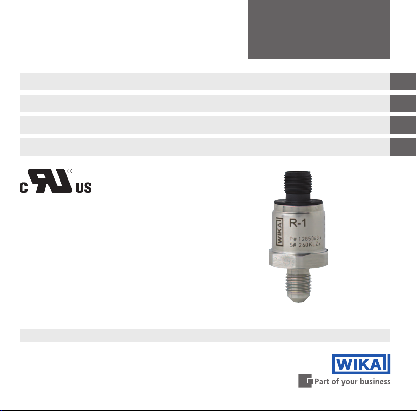
Pressure transmitter, model R-1
Druckmessumformer, Typ R-1
Transmetteur de pression, type R-1
Transmisor de presión, modelo R-1
Pressure transmitter, model R-1
GB
D
F
E
Page 2

GB
Operating instructions model R-1 Page 3 - 24
D
Betriebsanleitung Typ R-1 Seite 25 - 46
F
Mode d'emploi type R-1 Page 47 - 69
E
Manual de instrucciones modelo R-1 Página 70 - 91
© 2012 WIKA Alexander Wiegand SE & Co. KG
All rights reserved. / Alle Rechte vorbehalten.
WIKA® is a registered trademark in various countries.
WIKA® ist eine geschützte Marke in verschiedenen Ländern.
Prior to starting any work, read the operating instructions!
Keep for later use!
Vor Beginn aller Arbeiten Betriebsanleitung lesen!
Zum späteren Gebrauch aufbewahren!
Lire le mode d'emploi avant de commencer toute opération !
A conserver pour une utilisation ultérieure !
¡Leer el manual de instrucciones antes de comenzar cualquier trabajo!
¡Guardar el manual para una eventual consulta!
2 WIKA operating instructions pressure transmitter, model R-1
14026284.01 11/2012 GB/D/F/E
Page 3

Contents
Contents
1. General information 4
2. Safety 6
3. Specications 9
4. Design and function 15
5. Transport, packaging and storage 15
6. Commissioning, operation 16
7. Maintenance and cleaning 21
8. Faults 21
9. Dismounting, return and disposal 23
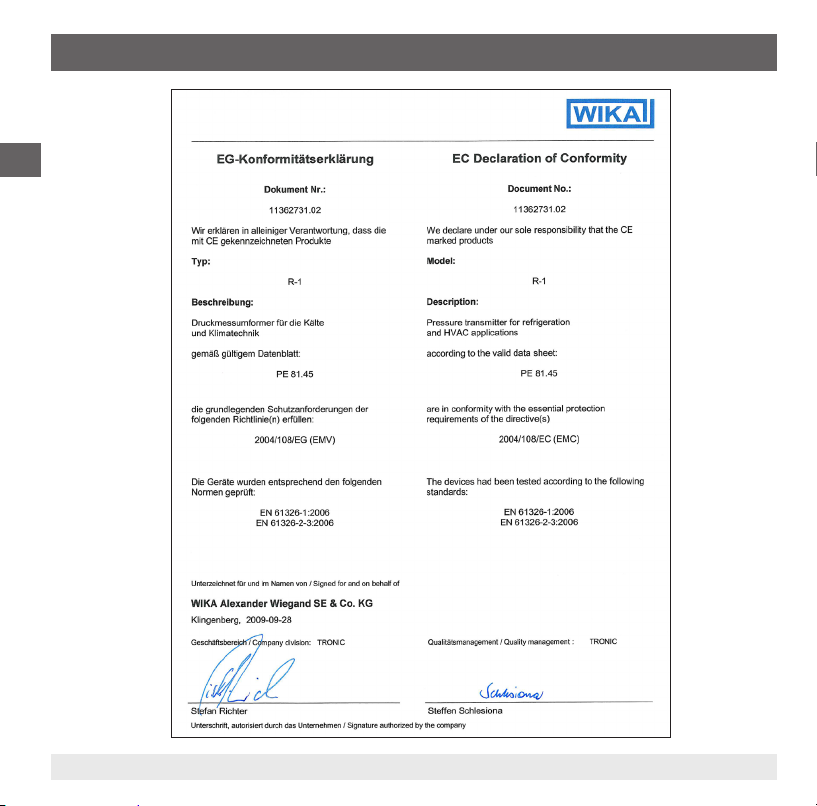
Appendix 1: EC Declaration of conformity model R-1 24
GB
Declarations of conformity can be found online at www.wika.com.
14026284.01 11/2012 GB/D/F/E
3WIKA operating instructions pressure transmitter, model R-1
Page 4

1. General information
1. General information
■
The pressure transmitter described in the operating instructions has been designed and
GB
manufactured using state-of-the-art technology. All components are subject to stringent quality and
environmental criteria during production. Our management systems are certied to ISO 9001 and
ISO 14001.
■
These operating instructions contain important information on handling the instrument. Working
safely requires that all safety instructions and work instructions are observed.
■
Observe the relevant local accident prevention regulations and general safety regulations for the
instrument's range of use.
■
The operating instructions are part of the product and must be kept in the immediate vicinity of the
instrument and readily accessible to skilled personnel at any time.
■
Skilled personnel must have carefully read and understood the operating instructions prior to
beginning any work.
■
The manufacturer's liability is void in the case of any damage caused by using the product contrary
to its intended use, non-compliance with these operating instructions, assignment of insuciently
qualied skilled personnel or unauthorised modications to the instrument.
■
The general terms and conditions contained in the sales documentation shall apply.
■
Subject to technical modications.
■
Further information:
- Internet address: www.wika.de / www.wika.com
- Relevant data sheet: PE 81.45
- Application consultant:
Tel.: (+49) 9372/132-8976
Fax: (+49) 9372/132-8008976
E-mail: support-tronic@wika.de
4 WIKA operating instructions pressure transmitter, model R-1
14026284.01 11/2012 GB/D/F/E
Page 5
1. General information
Explanation of symbols
WARNING!
... indicates a potentially dangerous situation that can result in serious injury or death, if not
avoided.
CAUTION!
... indicates a potentially dangerous situation that can result in light injuries or damage to the
equipment or the environment, if not avoided.
Information
... points out useful tips, recommendations and information for ecient and trouble-free
operation.
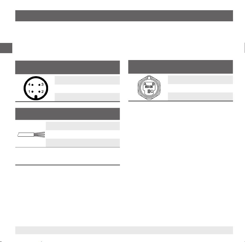
Abbreviations
2-wire The two connection lines are used for the voltage supply.
The measurement signal also provides the supply current.
3-wire Two connection lines are used for the power supply.
One connection line is used for the measurement signal.
GB
U
B
0V Negative power supply terminal
S
+
14026284.01 11/2012 GB/D/F/E
Positive power supply terminal
Positive output terminal
5WIKA operating instructions pressure transmitter, model R-1
Page 6
2. Safety
2. Safety
WARNING!
GB
2.1 Intended use
The pressure transmitter is used to convert pressure into an electrical signal.
The instrument has been designed and built solely for the intended use described here, and may only
be used accordingly.
The technical specications contained in these operating instructions must be observed.
Improper handling or operation of the pressure transmitter outside of its technical specications requires
the instrument to be taken out of service immediately and inspected by an authorised WIKA service
engineer.
Before installation, commissioning and operation, ensure that the appropriate pressure
transmitter has been selected in terms of measuring range, design and specic measuring
conditions.
Non-observance can result in serious injury and/or damage to the equipment.
WARNING!
■
Open the connections only after the system has been depressurised.
■
Observe the working conditions in accordance with chapter 3 "Specications".
■
Always operate the pressure transmitter within the overpressure limit.
Further important safety instructions can be found in the individual chapters of these
operating instructions.
The manufacturer shall not be liable for claims of any type based on operation contrary to the intended use.
6 WIKA operating instructions pressure transmitter, model R-1
14026284.01 11/2012 GB/D/F/E
Page 7
2. Safety
2.2 Personnel qualication
WARNING!
Risk of injury should qualication be insucient!
Improper handling can result in considerable injury and damage to equipment.
The activities described in these operating instructions may only be carried out by skilled
personnel who have the qualications described below.
Skilled personnel
Skilled personnel are understood to be personnel who, based on their technical training, knowledge
of measurement and control technology and on their experience and knowledge of country-specic
regulations, current standards and directives, are capable of carrying out the work described and
independently recognising potential hazards.
Special operating conditions require further appropriate knowledge, e.g. of aggressive media.
2.3 Special hazards
WARNING!
For hazardous media such as oxygen, acetylene, ammable or toxic gases or liquids,
and refrigeration plants, compressors, etc., in addition to all standard regulations, the
appropriate existing codes or regulations must also be followed.
WARNING!
Residual media in dismounted pressure transmitters can result in a risk to persons, the
environment and equipment.
Take sucient precautionary measures.
GB
14026284.01 11/2012 GB/D/F/E
7WIKA operating instructions pressure transmitter, model R-1
Page 8
2. Safety
2.4 Labelling, safety marks
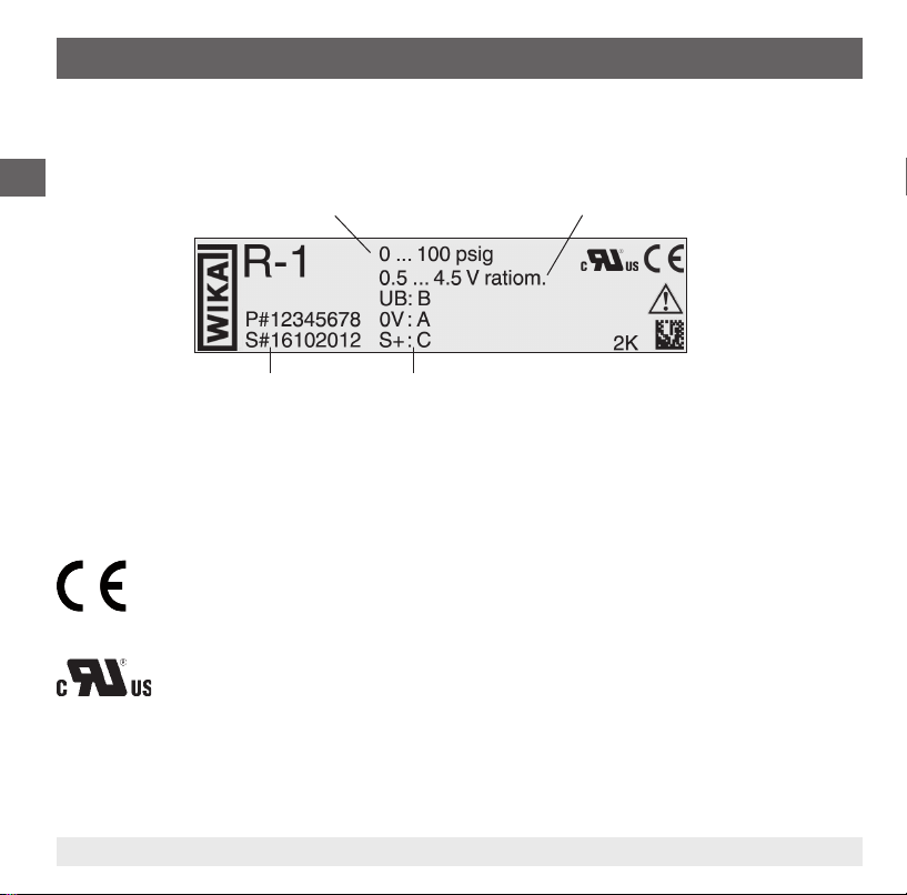
Product label
GB
Measuring range
Output signal
P# Product no.
S# Serial no.
Pin assignment
If the serial number and the 2D code become illegible due to mechanical damage or overpainting,
traceability will no longer be possible.
Explanation of symbols
CE, Communauté Européenne
Instruments bearing this mark comply with the relevant European directives.
cRUus, Underwriters Laboratories Inc.
®
The instrument was inspected in accordance with the applicable US standards and
certied by UL. The UL Recognized Component Mark denotes components recognised
by UL that serve as a component of another product.
8 WIKA operating instructions pressure transmitter, model R-1
14026284.01 11/2012 GB/D/F/E
Page 9

3. Specications
3. Specications
3.1 Measuring ranges
Relative pressure
bar Measuring range 0 ... 6 0 ... 10 0 ... 15 0 ... 16 0 ... 20 0 ... 25 0 ... 30
Overpressure limit 20 20 32 32 50 50 80
Burst pressure 100 100 160 160 250 250 400
Measuring range 0 ... 35 0 ... 40 0 ... 45 0 ... 50 0 ... 60 0 ... 100 0 ... 160
Overpressure limit 80 80 120 120 120 200 320
Burst pressure 400 400 550 550 550 800 1,000
psi Measuring range 0 ... 100 0 ... 150 0 ... 200 0 ... 250 0 ... 300 0 ... 350 0 ... 400
Overpressure limit 290 290 460 460 720 720 720
Burst pressure 1,450 1,450 2,300 2,300 3,600 3,600 3,600
Measuring range 0 ... 450 0 ... 500 0 ... 550 0 ... 600 0 ... 650 0 ... 700 0 ... 750
Overpressure limit 1,100 1,100 1,100 1,100 1,100 1,700 1,700
Burst pressure 5,800 5,800 5,800 5,800 5,800 7,900 7,900
Measuring range 0 ... 800 0 ... 850 0 ... 1,500 0 ... 2,400
Overpressure limit 1,700 1,700 2,900 4,600
Burst pressure 7,900 7,900 11,600 14,500
GB
14026284.01 11/2012 GB/D/F/E
9WIKA operating instructions pressure transmitter, model R-1
Page 10

3. Specications
Vacuum and +/- measuring range
bar Measuring range -1 ... +7 -1 ... +9 -1 ... +10 -1 ... +15
GB
Overpressure limit 20 20 20 32
Burst pressure 100 100 100 160
Measuring range -1 ... +20 -1 ... +25 -1 ... +29 -1 ... +45
Overpressure limit 50 50 80 120
Burst pressure 250 250 400 550
Measuring range -0.5 ... +7 -0.5 ... +10
Overpressure limit 20 20
Burst pressure 100 100
-30
inHg
psi Measuring range -30 inHg ... +100
Overpressure limit 290 290 460 460
Burst pressure 1,450 1,450 2,300 2,300
-30
inHg
-30
inHg
... +300 -30
... +500 -30
Measuring range
Overpressure limit 720 720 1,100 1,100
Burst pressure 3,600 3,600 5,800 5,800
Measuring range
Overpressure limit 1,100 1,100 1,700
Burst pressure 5,800 5,800 7,900
... +145 -30
inHg
... +350 -30
inHg
... +550 -30
inHg
... +200 -30
inHg
... +400 -30
inHg
... +600
Other measuring ranges on request
Vacuum tightness
Yes
inHg
inHg
... +250
... +450
10 WIKA operating instructions pressure transmitter, model R-1
14026284.01 11/2012 GB/D/F/E
Page 11

3. Specications
3.2 Output signals
Signal type Signal
Current (2-wire) 4 ... 20 mA
Voltage (3-wire) DC 0 ... 10 V
Ratiometric (3-wire) DC 0.5 ... 4.5 V
DC 1 ... 5 V
Other output signals available on request
Load in Ω
■
Current output (2-wire): ≤ (power supply - 7 V) / 0.02 A
■
Voltage output (3-wire): > maximum output signal / 1 mA
■
Ratiometric output (3-wire): > maximum output signal / 1 mA
3.3 Voltage supply
Power supply
The power supply depends on the selected output signal
■
4 ... 20 mA: DC 7 ...30 V
■
DC 1 ... 5 V: DC 8 ...30 V
■
DC 0 ... 10 V: DC 14 ... 30 V
■
DC 0.5 ... 4.5 V: DC 4.5 ... 5.5 V
GB
14026284.01 11/2012 GB/D/F/E
11WIKA operating instructions pressure transmitter, model R-1
Page 12

3. Specications
3.4 Reference conditions (per IEC 61298-1)
Temperature
15 ... 25 °C
GB
Atmospheric pressure
860 ... 1,060 mbar
Humidity
45 ... 75 % relative
Power supply
DC 24 V
Nominal position
Calibrated in vertical mounting position with pressure connection facing downwards.
3.5 Accuracy data
Accuracy at reference conditions
≤ 2 % of span
Including non-linearity, hysteresis, zero oset and end value deviation (corresponds to measured error
per IEC 61298-2).
Temperature error at -25 ... +85 °C
Mean temperature coecient of zero point: typical ≤ 0.5% of span/10 K
Mean temperature coecient of span: ≤ 0.3 % of span/10 K
12 WIKA operating instructions pressure transmitter, model R-1
14026284.01 11/2012 GB/D/F/E
Page 13

3. Specications
Settling time
≤ 5 ms
Long-term drift (per IEC 61298-2)
≤ 0.3 % of span/year
3.6 Operating conditions
Ingress protection (per IEC 60529)
The ingress protection depends on the type of electrical connection.
■
Circular connector M12 x 1: IP 67
■
Metri-Pack series 150: IP 67
■
Cable outlet: IP 69K
The stated ingress protection only applies when plugged in using mating connectors that have the
appropriate ingress protection.
Temperatures
■
Medium: -40 ... +100 °C -40 ... +212 °F
■
Ambient: -25 ... +85 °C -13 ... +185 °F
■
Storage: -25 ... +85 °C -13 ... +185 °F
Resistance
The pressure transmitter is resistant to the industrial standard refrigerants
GB
14026284.01 11/2012 GB/D/F/E
13WIKA operating instructions pressure transmitter, model R-1
Page 14

3. Specications
3.7 Electrical connections
Short-circuit resistance
S+ vs. 0V
GB
Reverse polarity protection
UB vs. 0V
Overvoltage protection
maximum DC 36 V
Insulation voltage
DC 500 V
3.8 Materials
Wetted parts
Sensor and process connection from stainless steel
Non-wetted parts
■
Case from stainless steel
■
Electrical connection from highly resistant, glass-bre reinforced plastic PBT GF 30
3.9 Approvals, directives and certicates
Approvals
cRUus (recognition)
CE conformity
EMC directive 2004/108/EC, EN 61326 emission (group 1, class B) and interference immunity (industrial application)
14 WIKA operating instructions pressure transmitter, model R-1
14026284.01 11/2012 GB/D/F/E
Page 15

3. Specications / 4. Design and function / 5. Transport ...
For special model numbers, e.g. R-10000, please note the specications stated on the delivery note.
For further specications see WIKA data sheet PE 81.45 and the order documentation.
4. Design and function
4.1 Description
The prevailing pressure is measured at the sensor element through the deformation of a diaphragm.
By supplying power, this deformation of the diaphragm is converted into an electrical signal. The output
signal from the pressure transmitter is amplied and standardised. The output signal is proportional to
the measured pressure.
4.2 Scope of delivery
Cross-check scope of delivery with delivery note.
5. Transport, packaging and storage
5.1 Transport
Check the pressure transmitter for any damage that may have been caused during transportation.
Obvious damage must be reported immediately.
5.2 Packaging
Do not remove packaging until just before mounting.
Keep the packaging as it will provide optimum protection during transport (e.g. change in installation
site, sending for repair).
GB
14026284.01 11/2012 GB/D/F/E
15WIKA operating instructions pressure transmitter, model R-1
Page 16
5. Transport, packaging and storage / 6. Commissioning, operation
5.3 Storage
Permissible conditions at the place of storage:
Storage temperature: -25 ... +80 °C
GB
WARNING!
Before storing the pressure transmitter (following operation), remove any residual media.
This is of particular importance if the medium is hazardous to health, e.g. caustic, toxic,
carcinogenic, radioactive, etc.
6. Commissioning, operation
CAUTION!
Prior to commissioning, the pressure transmitter must be subjected to a visual inspection.
Only use the pressure transmitter if it is in perfect condition with respect to safety.
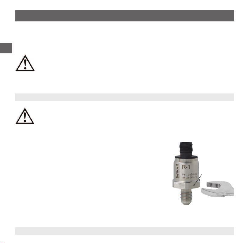
6.1 Making the mechanical connection
■
The sealing faces at the pressure transmitter and the measuring
point always have to be clean.
■
Only ever screw in, or unscrew, the instrument via the spanner ats.
Never use the case or the cooling element as a working surface.
■
The correct torque depends on the dimensions of the process
connection and the gasket used (form/material).
■
When screwing in, do not cross the threads.
■
For information on tapped holes and welding sockets, see
Technical Information IN 00.14 at www.wika.com.
Spanner ats
16 WIKA operating instructions pressure transmitter, model R-1
14026284.01 11/2012 GB/D/F/E
Page 17
6. Commissioning, operation
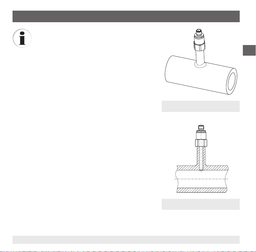
Humidity can aect the operating characteristics of
electronic components and sensors, thus a good
positioning prevents problems and extends the
service life. Electronic components and sensors can
be adversely aected due to temperature changes in
combination with condensing humidity (e.g. in evaporators with de-icing systems).
Although the ingress protection of the pressure
transmitter is IP 67 or IP 6K9K, this is not hermetically
sealed. Under critical conditions, there is the danger
that small air volumes can penetrate or diuse
through the case. Thus, over time, humidity can
collect in the sensor and cause measuring errors.
It is therefore recommended that the pressure transmitter is placed in a location with low humidity and
temperature uctuations. For chill cabinets or cold
rooms, this place is on the inlet pipe on the outside of
the main cooling chamber, e.g. below the chill cabinet
where the piping comes out of the chill cabinet.
If positioning is required closer to the evaporator, it is
recommended that a capillary is used between the
evaporator outlet line and the pressure transmitter.
Fig.: Pressure transmitter with capillary
(exterior view)
GB
14026284.01 11/2012 GB/D/F/E
Fig.: Pressure transmitter with capillary
(cross-section)
17WIKA operating instructions pressure transmitter, model R-1
Page 18
6. Commissioning, operation
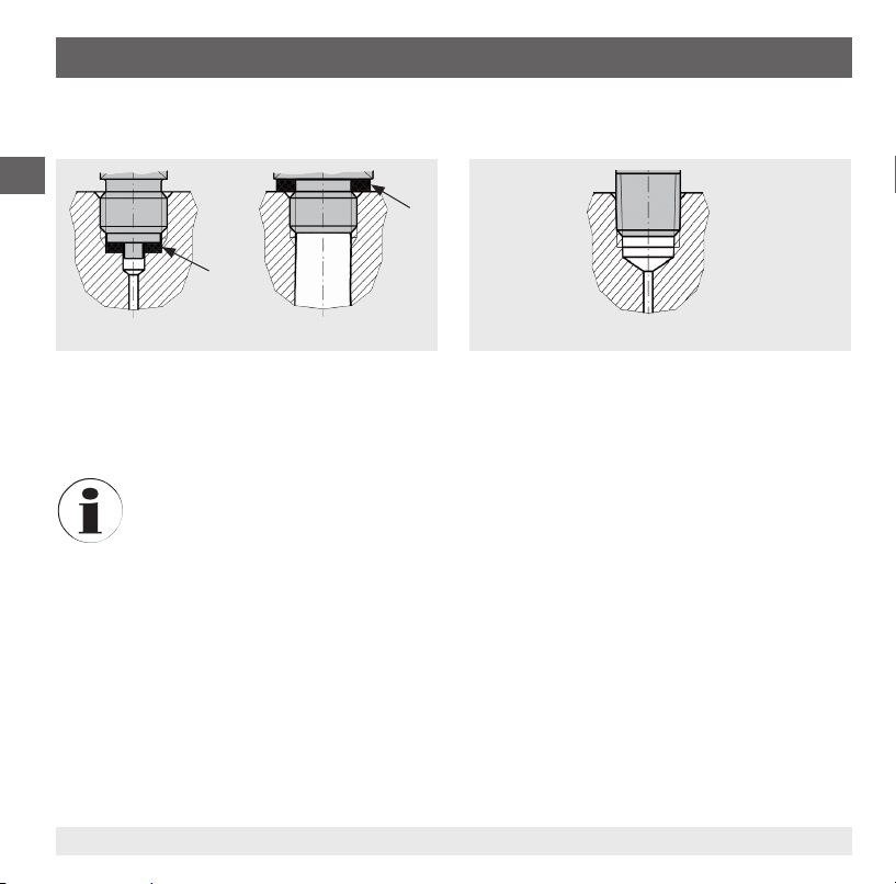
Sealing of the process connection
Parallel threads
GB
Tapered threads
per EN 837 per DIN 3852-E
Correct sealing of the process connections with
parallel threads at the sealing face must be
made using suitable at gaskets, sealing rings or
WIKA prole sealings.
For further information on seals see WIKA data sheet AC 09.08 or at www.wika.com.
6.2 Making the electrical connection
■
The instrument must be grounded via the process connection!
■
The power supply for the pressure transmitter must be made via an energy-limited electrical circuit
in accordance with section 9.3 of UL/EN/IEC 61010-1, or an LPS to UL/EN/IEC 60950-1, or class 2
in accordance with UL1310/UL1585 (NEC or CEC). The power supply must be suitable for operation
above 2,000 m should the pressure transmitter be used at this altitude.
■
For the voltage supply, use a class 2 voltage source.
For sealing process connections with tapered
threads, the sealing must be made in the threads
using additional sealing material - e.g. PTFE tape
(EN 837-2).
NPT, R and PT
18 WIKA operating instructions pressure transmitter, model R-1
14026284.01 11/2012 GB/D/F/E
Page 19

6. Commissioning, operation
■
Conditions of acceptability - When installed in the nal use equipment, etc., the following are among
the considerations to be made:
1. The instrument must be installed in accordance with the enclosure, mounting, spacing, and segregation requirements of the nal application.
2. The clearances given here (air and leakage paths), nominal values, etc. must be permissible
within the nal application.
3. This component is intended to be factory installed only.
4. The connectors of these instruments have not been tested for their suitability for eld wiring
connectors ("eld wiring"). The acceptability of the terminals, and connections to these terminals,
including temperature and safety, must be evaluated in the end-product application.
5. On the instrument, there is no isolated equipotential bonding terminal or connection line available
(that would maintain the equipotential bonding during dismantling in the live state by a service
technician for testing or setting purposes). This requirement depends on the application and the
standards applicable to the end product.
6. The mould stress test was conducted at 110 °C and the suitability will be dened with the
end-product application.
■
Select a cable diameter that matches the cable gland of the plug. Make sure that the cable gland of
the mounted plug has a tight t and that the seals are present and undamaged. Tighten the threaded
connection and check that the seal is correctly seated, in order to ensure the ingress protection.
■
For cable outlets, make sure that no moisture enters at the cable end.
GB
14026284.01 11/2012 GB/D/F/E
19WIKA operating instructions pressure transmitter, model R-1
Page 20
6. Commissioning, operation
For the output signals DC 1 ... 5 V and DC 0.5 ... 4.5 V ratiometric, the following applies in addition:
If the cable of the electrical connection is longer than 30 m or leaves the building, then the pressure
transmitter should be used with a shielded cable. Earth the shield on at least one end of the lead.
GB
Connection diagrams
Circular connector M12 x 1
2-wire 3-wire
UB1 1
0V 3 3
S+ - 4
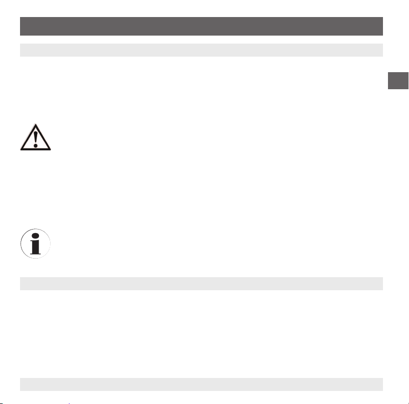
Metri-Pack series 150
2-wire 3-wire
UBB B
0V C A
S+ - C
Cable outlet, unshielded
2-wire 3-wire
U+brown brown
U-green green
- white
S
+
Wire cross-section 3 x 0.14 mm
Cable diameter 3.2 mm
Cable lengths 1 m
2
20 WIKA operating instructions pressure transmitter, model R-1
14026284.01 11/2012 GB/D/F/E
Page 21
7. Maintenance and cleaning / 8. Faults
7. Maintenance and cleaning
7.1 Maintenance
This pressure transmitter is maintenance-free.
Repairs must only be carried out by the manufacturer.
7.2 Cleaning
CAUTION!
■
Before cleaning, correctly disconnect the pressure transmitter from the pressure supply,
switch it o and disconnect it from the mains.
■
Clean the instrument with a moist cloth.
■
Wash or clean the dismounted instrument before returning it, in order to protect persons
and the environment from exposure to residual media.
■
Residual media in dismounted instruments can result in a risk to persons, the
environment and equipment. Take sucient precautionary measures.
■
Do not use any pointed or hard objects for cleaning, as they may damage the diaphragm
of the process connection.
For information on returning the instrument see chapter 9.2 "Return".
8. Faults
In the event of any faults, rst check whether the pressure transmitter is mounted correctly, mechanically
and electrically.
GB
14026284.01 11/2012 GB/D/F/E
21WIKA operating instructions pressure transmitter, model R-1
Page 22
8. Faults
Faults Causes Measures
Constant output signal upon
change in pressure
GB
No/wrong output signal Wiring error Observe the pin assignment
No output signal No/wrong power supply or current
Signal span too small Power supply too high/low
Signal span drops Moisture has entered
Signal span varies EMC interference sources in the
CAUTION!
If faults cannot be eliminated by means of the measures listed above, shut down the
pressure transmitter immediately, and ensure that pressure and/or signal are no longer
present, and secure the instrument from being put back into operation inadvertently. In this
case, contact the manufacturer. If a return is needed, please follow the instructions given in
chapter 9.2 "Return".
Mechanical overload caused by
overpressure
Wrong power supply or current pulse
pulse
Cable break
Mechanical overload caused by
overpressure
Diaphragm defective
environment
Instrument not earthed
Strongly varying power supply
Strongly varying pressure of the
process medium
Replace instrument; if it fails repeatedly,
contact the manufacturer
Rectify the power supply
Check the continuity
Rectify the power supply
Replace instrument; if it fails repeatedly,
contact the manufacturer
Fit the cable correctly
Replace instrument; if it fails repeatedly,
contact the manufacturer
Shield instrument; cable shield; remove
source of interference
Earth the instrument
Stabilise the power supply
Damping, consulting by the manufacturer
22 WIKA operating instructions pressure transmitter, model R-1
14026284.01 11/2012 GB/D/F/E
Page 23
9. Dismounting, return and disposal
9. Dismounting, return and disposal
WARNING!
Residual media in dismounted pressure transmitters can result in a risk to persons, the
environment and equipment.
Take sucient precautionary measures.
9.1 Dismounting
Only disconnect the pressure transmitter once the system has been depressurised!
9.2 Return
WARNING!
Absolutely observe when shipping the pressure transmitter:
All pressure transmitters delivered to WIKA must be free from any kind of hazardous
substances (acids, bases, solutions, etc.).
When returning the instrument, use the original packaging or a suitable transport package.
Information on returns can be found under the heading "Service" on our local website.
9.3 Disposal
Incorrect disposal can put the environment at risk.
Dispose of instrument components and packaging materials in an environmentally compatible way and
in accordance with the country-specic waste disposal regulations.
GB
14026284.01 11/2012 GB/D/F/E
23WIKA operating instructions pressure transmitter, model R-1
Page 24
Appendix 1: EC Declaration of conformity model R-1
GB
24 WIKA operating instructions pressure transmitter, model R-1
14026284.01 11/2012 GB/D/F/E
Page 25
Inhalt
Inhalt
1. Allgemeines 26
2. Sicherheit 28
3. Technische Daten 31
4. Aufbau und Funktion 37
5. Transport, Verpackung und Lagerung 37
6. Inbetriebnahme, Betrieb 38
7. Wartung und Reinigung 43
8. Störungen 43
9. Demontage, Rücksendung und Entsorgung 45
Anlage 1: EG-Konformitätserklärung Typ R-1 46
Konformitätserklärungen nden Sie online unter www.wika.de.
14026284.01 11/2012 GB/D/F/E
D
25WIKA Betriebsanleitung Druckmessumformer, Typ R-1
Page 26

1. Allgemeines
1. Allgemeines
■
Der in der Betriebsanleitung beschriebene Druckmessumformer wird nach dem aktuellen Stand der
Technik konstruiert und gefertigt.
Alle Komponenten unterliegen während der Fertigung strengen Qualitäts- und Umweltkriterien.
Unsere Managementsysteme sind nach ISO 9001 und ISO 14001 zertiziert.
D
■
Diese Betriebsanleitung gibt wichtige Hinweise zum Umgang mit dem Gerät. Voraussetzung
für sicheres Arbeiten ist die Einhaltung aller angegebenen Sicherheitshinweise und
Handlungsanweisungen.
■
Die für den Einsatzbereich des Gerätes geltenden örtlichen Unfallverhütungsvorschriften und
allgemeinen Sicherheitsbestimmungen einhalten.
■
Die Betriebsanleitung ist Produktbestandteil und muss in unmittelbarer Nähe des Gerätes für das
Fachpersonal jederzeit zugänglich aufbewahrt werden.
■
Das Fachpersonal muss die Betriebsanleitung vor Beginn aller Arbeiten sorgfältig durchgelesen und
verstanden haben.
■
Die Haftung des Herstellers erlischt bei Schäden durch bestimmungswidrige Verwendung,
Nichtbeachten dieser Betriebsanleitung, Einsatz ungenügend qualizierten Fachpersonals sowie
eigenmächtiger Veränderung am Gerät.
■
Es gelten die allgemeinen Geschäftsbedingungen in den Verkaufsunterlagen.
■
Technische Änderungen vorbehalten.
■
Weitere Informationen:
- Internet-Adresse: www.wika.de / www.wika.com
- zugehöriges Datenblatt: PE 81.45
- Anwendungsberater:
Tel.: (+49) 9372/132-8976
Fax: (+49) 9372/132-8008976
E-Mail: support-tronic@wika.de
26 WIKA Betriebsanleitung Druckmessumformer, Typ R-1
14026284.01 11/2012 GB/D/F/E
Page 27
1. Allgemeines
Symbolerklärung
WARNUNG!
… weist auf eine möglicherweise gefährliche Situation hin, die zum Tod oder zu schweren
Verletzungen führen kann, wenn sie nicht gemieden wird.
VORSICHT!
… weist auf eine möglicherweise gefährliche Situation hin, die zu geringfügigen oder
leichten Verletzungen bzw. Sach- und Umweltschäden führen kann, wenn sie nicht
gemieden wird.
Information
… hebt nützliche Tipps und Empfehlungen sowie Informationen für einen ezienten und
störungsfreien Betrieb hervor.
Abkürzungen
2-Leiter Die zwei Anschlussleitungen dienen zur Spannungsversorgung.
Der Speisestrom ist das Messsignal.
3-Leiter Zwei Anschlussleitungen dienen zur Spannungsversorgung.
Eine Anschlussleitung dient für das Messsignal.
D
U
B
0V Negativer Versorgungsanschluss
S
+
14026284.01 11/2012 GB/D/F/E
Positiver Versorgungsanschluss
Positiver Messanschluss
27WIKA Betriebsanleitung Druckmessumformer, Typ R-1
Page 28
2. Sicherheit
2. Sicherheit
WARNUNG!
Vor Montage, Inbetriebnahme und Betrieb sicherstellen, dass der richtige
Druckmessumformer hinsichtlich Messbereich, Ausführung und spezischen
D
2.1 Bestimmungsgemäße Verwendung
Der Druckmessumformer dient zum Umwandeln von Druck in ein elektrisches Signal.
Das Gerät ist ausschließlich für den hier beschriebenen bestimmungsgemäßen Verwendungszweck
konzipiert und konstruiert und darf nur dementsprechend verwendet werden.
Die technischen Spezikationen in dieser Betriebsanleitung sind einzuhalten. Eine unsachgemäße
Handhabung oder ein Betreiben des Druckmessumformers außerhalb der technischen Spezikationen
macht die sofortige Stilllegung und Überprüfung durch einen autorisierten WIKA-Servicemitarbeiter
erforderlich.
Messbedingungen ausgewählt wurde.
Bei Nichtbeachten können schwere Körperverletzungen und/oder Sachschäden auftreten.
WARNUNG!
■
Anschlüsse nur im drucklosen Zustand önen.
■
Betriebsparameter gemäß Kapitel 3 „Technische Daten“ beachten.
■
Druckmessumformer immer innerhalb der Überlast-Druckgrenze betreiben.
Weitere wichtige Sicherheitshinweise benden sich in den einzelnen Kapiteln dieser
Betriebsanleitung.
Ansprüche jeglicher Art aufgrund von nicht bestimmungsgemäßer Verwendung sind ausgeschlossen.
28 WIKA Betriebsanleitung Druckmessumformer, Typ R-1
14026284.01 11/2012 GB/D/F/E
Page 29

2. Sicherheit
2.2 Personalqualikation
WARNUNG!
Verletzungsgefahr bei unzureichender Qualikation!
Unsachgemäßer Umgang kann zu erheblichen Personen- und Sachschäden führen.
Die in dieser Betriebsanleitung beschriebenen Tätigkeiten nur durch Fachpersonal nachfolgend beschriebener Qualikation durchführen lassen.
Fachpersonal
Das Fachpersonal ist aufgrund seiner fachlichen Ausbildung, seiner Kenntnisse der Mess- und
Regelungstechnik und seiner Erfahrungen sowie Kenntnis der landesspezischen Vorschriften,
geltenden Normen und Richtlinien in der Lage, die beschriebenen Arbeiten auszuführen und mögliche
Gefahren selbstständig zu erkennen.
Spezielle Einsatzbedingungen verlangen weiteres entsprechendes Wissen, z. B. über aggressive
Medien.
2.3 Besondere Gefahren
WARNUNG!
Bei gefährlichen Messstoen wie z. B. Sauersto, Acetylen, brennbaren oder giftigen
Stoen, sowie bei Kälteanlagen, Kompressoren etc. müssen über die gesamten
allgemeinen Regeln hinaus die einschlägigen Vorschriften beachtet werden.
WARNUNG!
Messstoreste in ausgebauten Druckmessumformern können zur Gefährdung von
Personen, Umwelt und Einrichtung führen.
Ausreichende Vorsichtsmaßnahmen ergreifen.
D
14026284.01 11/2012 GB/D/F/E
29WIKA Betriebsanleitung Druckmessumformer, Typ R-1
Page 30

2. Sicherheit
2.4 Beschilderung, Sicherheitskennzeichnungen
Typenschild
D
P# Erzeugnis-Nr.
S# Serien-Nr.
Messbereich
Anschlussbelegung
Ausgangssignal
Wird die Seriennummer und der 2D-Code durch mechanische Beschädigung oder Übermalen
unleserlich, ist eine Rückverfolgbarkeit nicht mehr möglich.
Symbolerklärung
CE, Communauté Européenne
Geräte mit dieser Kennzeichnung stimmen überein mit den zutreenden europäischen
Richtlinien.
cRUus, Underwriters Laboratories Inc.
®
Das Gerät wurde nach den anwendbaren US-amerikanischen Normen geprüft und
von UL zertiziert. Die Recognized Component Mark kennzeichnet von UL anerkannte
Komponenten, die als Bauteil eines anderen Produktes dienen.
30 WIKA Betriebsanleitung Druckmessumformer, Typ R-1
14026284.01 11/2012 GB/D/F/E
Page 31

3. Technische Daten
3. Technische Daten
3.1 Messbereiche
Relativdruck
bar Messbereich 0 ... 6 0 ... 10 0 ... 15 0 ... 16 0 ... 20 0 ... 25 0 ... 30
Überlast-Druckgrenze 20 20 32 32 50 50 80
Berstdruck 100 100 160 160 250 250 400
Messbereich 0 ... 35 0 ... 40 0 ... 45 0 ... 50 0 ... 60 0 ... 100 0 ... 160
Überlast-Druckgrenze 80 80 120 120 120 200 320
Berstdruck 400 400 550 550 550 800 1.000
psi Messbereich 0 ... 100 0 ... 150 0 ... 200 0 ... 250 0 ... 300 0 ... 350 0 ... 400
Überlast-Druckgrenze 290 290 460 460 720 720 720
Berstdruck 1.450 1.450 2.300 2.300 3.600 3.600 3.600
Messbereich 0 ... 450 0 ... 500 0 ... 550 0 ... 600 0 ... 650 0 ... 700 0 ... 750
Überlast-Druckgrenze 1.100 1.100 1.100 1.100 1.100 1.700 1.700
Berstdruck 5.800 5.800 5.800 5.800 5.800 7.900 7.900
Messbereich 0 ... 800 0 ... 850 0 ... 1.500 0 ... 2.400
Überlast-Druckgrenze 1.700 1.700 2.900 4.600
Berstdruck 7.900 7.900 11.600 14.500
14026284.01 11/2012 GB/D/F/E
D
31WIKA Betriebsanleitung Druckmessumformer, Typ R-1
Page 32

3. Technische Daten
Vakuum- und +/- Messbereich
bar Messbereich -1 ... +7 -1 ... +9 -1 ... +10 -1 ... +15
Überlast-Druckgrenze 20 20 20 32
Berstdruck 100 100 100 160
D
Messbereich -1 ... +20 -1 ... +25 -1 ... +29 -1 ... +45
Überlast-Druckgrenze 50 50 80 120
Berstdruck 250 250 400 550
Messbereich -0,5 ... +7 -0,5 ... +10
Überlast-Druckgrenze 20 20
Berstdruck 100 100
-30
inHg
psi Messbereich -30 inHg ... +100
Überlast-Druckgrenze 290 290 460 460
Berstdruck 1.450 1.450 2.300 2.300
-30
inHg
-30
inHg
... +300 -30
... +500 -30
Messbereich
Überlast-Druckgrenze 720 720 1.100 1.100
Berstdruck 3.600 3.600 5.800 5.800
Messbereich
Überlast-Druckgrenze 1.100 1.100 1.700
Berstdruck 5.800 5.800 7.900
... +145 -30
inHg
... +350 -30
inHg
... +550 -30
inHg
... +200 -30
inHg
... +400 -30
inHg
... +600
Weitere Messbereiche auf Anfrage
Vakuumfestigkeit
Ja
inHg
inHg
... +250
... +450
32 WIKA Betriebsanleitung Druckmessumformer, Typ R-1
14026284.01 11/2012 GB/D/F/E
Page 33

3. Technische Daten
3.2 Ausgangssignale
Signalart Signal
Strom (2-Leiter) 4 ... 20 mA
Spannung (3-Leiter) DC 0 ... 10 V
Ratiometrisch (3-Leiter) DC 0,5 ... 4,5 V
Weitere Ausgangssignale auf Anfrage
Bürde in Ω
■
Stromausgang (2-Leiter): ≤ (Hilfsenergie - 7 V) / 0,02 A
■
Spannungsausgang (3-Leiter): > maximales Ausgangssignal / 1 mA
■
Ratiometrischer Ausgang (3-Leiter): > maximales Ausgangssignal / 1 mA
3.3 Spannungsversorgung
Hilfsenergie
Die Hilfsenergie ist abhängig vom gewählten Ausgangssignal
■
4 ... 20 mA: DC 7 ...30 V
■
DC 1 ... 5 V: DC 8 ...30 V
■
DC 0 ... 10 V: DC 14 ... 30 V
■
DC 0,5 ... 4,5 V: DC 4,5 ... 5,5 V
DC 1 ... 5 V
D
14026284.01 11/2012 GB/D/F/E
33WIKA Betriebsanleitung Druckmessumformer, Typ R-1
Page 34

3. Technische Daten
3.4 Referenzbedingungen (nach IEC 61298-1)
Temperatur
15 ... 25 °C
Luftdruck
D
860 ... 1.060 mbar
Luftfeuchte
45 ... 75 % relativ
Hilfsenergie
DC 24 V
Nennlage
Kalibriert bei senkrechter Einbaulage mit dem Prozessanschluss nach unten.
3.5 Genauigkeitsangaben
Genauigkeit bei Referenzbedingungen
≤ 2 % der Spanne
Einschließlich Nichtlinearität, Hysterese, Nullpunkt- und Endwertabweichung (entspricht Messabweichung nach IEC 61298-2).
Temperaturfehler bei -25 ... +85 °C
Mittlerer Temperaturkoezient des Nullpunktes: typisch ≤ 0,5 % der Spanne/10 K
Mittlerer Temperaturkoezient der Spanne: ≤ 0,3 % der Spanne/10 K
34 WIKA Betriebsanleitung Druckmessumformer, Typ R-1
14026284.01 11/2012 GB/D/F/E
Page 35

3. Technische Daten
Einschwingzeit
≤ 5 ms
Langzeitdrift (nach IEC 61298-2)
≤ 0,3 % der Spanne/Jahr
3.6 Einsatzbedingungen
Schutzart (nach IEC 60529)
Die Schutzart ist abhängig von der Art des elektrischen Anschlusses.
■
Rundstecker M12 x 1: IP 67
■
Metri-Pack Serie 150: IP 67
■
Kabelausgang: IP 69K
Die angegebenen Schutzarten gelten nur im gesteckten Zustand mit Gegensteckern entsprechender
Schutzart.
Temperaturen
■
Medium: -40 ... +100 °C -40 ... +212 °F
■
Umgebung: -25 ... +85 °C -13 ... +185 °F
■
Lagerung: -25 ... +85 °C -13 ... +185 °F
Beständigkeit
Der Druckmessumformer ist gegen handelsübliche Kältemittel beständig.
D
14026284.01 11/2012 GB/D/F/E
35WIKA Betriebsanleitung Druckmessumformer, Typ R-1
Page 36

3. Technische Daten
3.7 Elektrische Anschlüsse
Kurzschlussfestigkeit
S+ gegen 0V
Verpolschutz
D
UB gegen 0V
Überspannungsschutz
maximal DC 36 V
Isolationsspannung
DC 500 V
3.8 Werkstoe
Messstoberührte Teile
Sensor und Prozessanschluss aus CrNi-Stahl
Nicht messstoberührte Teile
■
Gehäuse aus CrNi-Stahl
■
Elektrischer Anschluss aus hochresistentem glasfaserverstärktem Kunststo PBT GF 30
3.9 Zulassungen, Richtlinien und Zertikate
Zulassungen
cRUus (recognition)
CE-Konformität
EMV-Richtline 2004/108/EG EN 61326 Emission (Gruppe 1, Klasse B) und Störfestigkeit (industrieller
Bereich)
36 WIKA Betriebsanleitung Druckmessumformer, Typ R-1
14026284.01 11/2012 GB/D/F/E
Page 37

3. Technische Daten / 4. Aufbau und Funktion / 5. Transport ...
Bei Sondertypennummer, z. B. R-10000 Spezikationen gemäß Lieferschein beachten.
Weitere technische Daten siehe WIKA-Datenblatt PE 81.45 und Bestellunterlagen.
4. Aufbau und Funktion
4.1 Beschreibung
Der anstehende Druck wird mittels Membranverformung am Sensorelement gemessen. Unter Zuführung von Hilfsenergie wird diese Membranverformung in ein elektrisches Signal umgewandelt. Das vom
Druckmessumformer ausgegebene Signal ist verstärkt und standardisiert. Das Ausgangssignal verhält
sich proportional zum gemessenen Druck.
4.2 Lieferumfang
Lieferumfang mit dem Lieferschein abgleichen.
5. Transport, Verpackung und Lagerung
5.1 Transport
Druckmessumformer auf eventuell vorhandene Transportschäden untersuchen.
Oensichtliche Schäden unverzüglich mitteilen.
5.2 Verpackung
Verpackung erst unmittelbar vor der Montage entfernen.
Die Verpackung aufbewahren, denn diese bietet bei einem Transport einen optimalen Schutz
(z. B. wechselnder Einbauort, Reparatursendung).
14026284.01 11/2012 GB/D/F/E
D
37WIKA Betriebsanleitung Druckmessumformer, Typ R-1
Page 38

5. Transport, Verpackung und Lagerung / 6. Inbetriebnahme, Betrieb
5.3 Lagerung
Zulässige Bedingungen am Lagerort:
Lagertemperatur: -25 ... +80 °C
D
WARNUNG!
Vor der Einlagerung des Druckmessumformers (nach Betrieb) alle anhaftenden
Messstoreste entfernen. Dies ist besonders wichtig, wenn der Messsto
gesundheitsgefährdend ist, wie z. B. ätzend, giftig, krebserregend, radioaktiv, usw.
6. Inbetriebnahme, Betrieb
VORSICHT!
Vor der Inbetriebnahme den Druckmessumformer optisch prüfen.
Den Druckmessumformer nur in sicherheitstechnisch einwandfreiem Zustand einsetzen.
6.1 Montage mechanischer Anschluss
■
Dichtächen am Druckmessumformer und der Messstelle müssen
stets frei von Verschmutzungen sein.
■
Das Gerät nur über die Schlüsselächen ein- bzw. ausschrauben.
Niemals das Gehäuse oder die Kühlstrecke als Angrisäche
verwenden.
■
Das richtige Drehmoment ist abhängig von der Dimension des
Prozessanschlusses sowie der verwendeten Dichtung (Form/
Werksto).
■
Beim Einschrauben die Gewindegänge nicht verkanten.
■
Angaben zu Einschraublöchern und Einschweißstutzen siehe
Technische Information IN 00.14 unter www.wika.de.
38 WIKA Betriebsanleitung Druckmessumformer, Typ R-1
Schlüsseläche
14026284.01 11/2012 GB/D/F/E
Page 39

6. Inbetriebnahme, Betrieb
Feuchtigkeit kann die Betriebseigenschaften elektronischer Komponenten und Sensoren
daher vermeidet eine gute Positionierung Probleme und verlängert die
Komponenten und Sensoren können durch Temperaturwechsel
in Kombination mit kondensierender
Feuchtigkeit negativ beeinusst werden (z. B. bei
Verdampfern mit Enteisungssystemen).
Obwohl die Schutzart des Druckmessumformers
IP 67 bzw. IP 6K9K beträgt, ist dieser nicht hermetisch dicht. Unter kritischen Bedingungen besteht
die Gefahr, dass ein kleines Luftvolumen durch das
Gehäuse eindringen oder diundieren kann. Im
Laufe der Zeit kann sich dadurch die Feuchtigkeit am
Sensor sammeln und Messfehler verursachen.
Es wird deshalb empfohlen, den Druckmessumformer an einer Stelle mit geringen Feuchte- und
Temperaturzyklen zu positionieren. Bei Gefriermöbeln oder Kühlräumen bendet sich diese Stelle an
der Ansaugleitung außerhalb der Hauptkühlkammer,
z. B. unterhalb des Gefriermöbels, wo die Verrohrung
herausführt.
Falls eine Positionierung näher am Verdampfer
verlangt wird, empehlt es sich eine Kapillar
zwischen der Ausgangsleitung des Verdampfers und
dem Druckmessumformer zu verwenden.
Lebensdauer. Elektronische
beeinussen,
leitung
Abb.: Druckmessumformer mit Kapillar-
leitung (Außenansicht)
Abb.: Druckmessumformer mit Kapillar-
leitung (Querschnitt)
D
14026284.01 11/2012 GB/D/F/E
39WIKA Betriebsanleitung Druckmessumformer, Typ R-1
Page 40

6. Inbetriebnahme, Betrieb
Abdichtung des Prozessanschlusses
Zylindrische Gewinde
Kegelige Gewinde
D
nach EN 837 nach DIN 3852-E
Zur Abdichtung der Prozessanschlüsse mit
zylindrischem Gewinde an der Dichtäche
sind Flachdichtungen, Dichtlinsen oder WIKAProldichtungen einzusetzen.
Hinweise zu Dichtungen siehe WIKA Datenblatt AC 09.08 oder unter www.wika.de.
6.2 Montage elektrischer Anschluss
■
Das Gerät über den Prozessanschluss erden.
■
Die Versorgung des Druckmessumformers muss durch einen energiebegrenzten Stromkreis gemäß
9.3 der UL/EN/IEC 61010-1 oder LPS gemäß UL/EN/IEC 60950-1 oder Class 2 gemäß UL1310/
UL1585 (NEC oder CEC) erfolgen. Die Stromversorgung muss für den Betrieb oberhalb 2.000 m
geeignet sein, falls der Druckmessumformer ab dieser Höhe verwendet wird.
■
Für die Spannungsversorgung eine Class 2 Spannungsquelle verwenden.
Zur Abdichtung der Prozessanschlüsse mit
kegeligem Gewinde erfolgt die Abdichtung im
Gewinde, mit zusätzlichen Dichtwerkstoen
z. B. PTFE-Band (EN 837-2).
40 WIKA Betriebsanleitung Druckmessumformer, Typ R-1
NPT, R und PT
14026284.01 11/2012 GB/D/F/E
Page 41

6. Inbetriebnahme, Betrieb
■
Abnahmebedingungen - Beim Einbau z. B in das Endgerät sind u.a. folgende Betrachtungen in
Erwägung zu ziehen:
1. Der Einbau des Geräts muss gemäß den Gehäuse-, Montage-, Platzbedarf- und Abgrenzungsanforderungen der Endanwendung erfolgen.
2. Die hierin angegebenen Abstände (Luft- und Kriechstrecken), Nennwerte usw. müssen bei der
Endanwendung zulässig sein.
3. Dieses Bauteil ist nur für werksseitigen Einbau vorgesehen.
4. Die Anschlüsse dieser Geräte wurden nicht auf ihre Eignung für Feldverdrahtungsanschlüsse („eld wiring“) überprüft. Die Akzeptanz der Anschlussklemmen und Anschlüsse an diese
Klemmen, einschließlich Temperatur und Sicherheit, muss in der bei der Endproduktanwendung
ermittelt werden.
5. Bei den Geräten ist keine getrennte Potentialausgleichsklemme bzw. Anschlussleitung vorhanden
(die bei Demontage im spannungsführenden Zustand durch einen Servicetechniker zu Prüfungsund Einstellzwecken den Potentialausgleich aufrechterhalten würde). Diese Anforderung hängt
vom Einsatz und der für das Endprodukt gültigen Norm ab.
6. Die Formspannungsprüfung („Mold Stress Test“) erfolgte bei 110 °C und die Eignung wird bei der
Endproduktanwendung festgelegt.
■
Den Kabeldurchmesser passend zur Kabeldurchführung des Steckers wählen. Sicherstellen, dass
die Kabelverschraubung des montierten Steckers korrekt sitzt und dass die Dichtungen vorhanden
und nicht beschädigt sind. Verschraubung festziehen und den korrekten Sitz der Dichtungen
überprüfen, um die Schutzart zu gewährleisten.
■
Bei Kabelausgängen sicherstellen, dass am Ende des Kabels keine Feuchtigkeit eintritt.
D
14026284.01 11/2012 GB/D/F/E
41WIKA Betriebsanleitung Druckmessumformer, Typ R-1
Page 42

6. Inbetriebnahme, Betrieb
Für die Ausgangssignale DC 1 ... 5 V und DC 0,5 ... 4,5 V ratiometrisch gilt zusätzlich:
Wenn das Kabel des elektrischen Anschlusses länger als 30 m ist oder das Gebäude verlässt, dann ist
der Druckmessumformer mit einem geschirmten Kabel zu betreiben. Den Schirm an mindestens einem
Leitungsende erden.
Anschlussschemen
D
Rundstecker M12 x 1
2-Leiter 3-Leiter
UB1 1
0V 3 3
S+ - 4
Kabelausgang, ungeschirmt
2-Leiter 3-Leiter
U+braun braun
U-grün grün
- weiß
S
+
Aderquerschnitt 3 x 0,14 mm
Kabeldurchmesser 3,2 mm
Kabellängen 1 m
2
Metri-Pack Serie 150
2-Leiter 3-Leiter
UBB B
0V C A
S+ - C
42 WIKA Betriebsanleitung Druckmessumformer, Typ R-1
14026284.01 11/2012 GB/D/F/E
Page 43

7. Wartung und Reinigung / 8. Störungen
7. Wartung und Reinigung
7.1 Wartung
Der Druckmessumformer ist wartungsfrei.
Reparaturen sind ausschließlich vom Hersteller durchzuführen.
7.2 Reinigung
VORSICHT!
■
Vor der Reinigung den Druckmessumformer ordnungsgemäß von der Druckversorgung
trennen, ausschalten und vom Netz trennen.
■
Das Gerät mit einem feuchten Tuch reinigen.
■
Ausgebautes Gerät vor der Rücksendung spülen bzw. säubern, um Personen und
Umwelt vor Gefährdung durch anhaftende Messstoreste zu schützen.
■
Messstoreste in ausgebauten Geräten können zur Gefährdung von Personen, Umwelt
und Einrichtung führen.
Ausreichende Vorsichtsmaßnahmen ergreifen.
■
Keine spitzen bzw. harten Gegenstände zur Reinigung verwenden, denn diese können
die Membrane des Prozessanschlusses beschädigen.
Hinweise zur Rücksendung des Gerätes siehe Kapitel 9.2 „Rücksendung“.
8. Störungen
Bei Störungen zuerst überprüfen, ob der Druckmessumformer mechanisch und elektrisch korrekt
montiert ist.
D
14026284.01 11/2012 GB/D/F/E
43WIKA Betriebsanleitung Druckmessumformer, Typ R-1
Page 44

8. Störungen
Störungen Ursachen Maßnahmen
Gleichbleibendes Ausgangssignal bei Druckänderung
Kein/Falsches Ausgangssignal Verdrahtungsfehler Anschlussbelegung beachten
D
Kein Ausgangssignal Keine/Falsche Hilfsenergeie oder
Signalspanne zu klein Hilfsenergie zu hoch/niedrig
Signalspanne fällt ab Feuchtigkeit eingetreten
Signalspanne schwankend EMV-Störquellen in der Umgebung
VORSICHT!
Können Störungen mit Hilfe der oben aufgeführten Maßnahmen nicht beseitigt werden, ist
der Druckmessumformer unverzüglich außer Betrieb zu setzen, sicherzustellen, dass kein
Druck bzw. Signal mehr anliegt und gegen versehentliche Inbetriebnahme zu schützen. In
diesem Falle Kontakt mit dem Hersteller aufnehmen. Bei notwendiger Rücksendung die
Hinweise unter Kapitel 9.2 „Rücksendung“ beachten.
Mechanische Überlastung durch
Überdruck
Falsche Hilfsenergie oder Stromstoß
Stromstoß
Leitungsbruch
Mechanische Überlastung durch
Überdruck
Membrane defekt
Gerät nicht geerdet
Stark schwankende Hilfsenergie
Stark schwankender Druck des
Prozessmediums
Gerät austauschen, bei wiederholtem
Ausfall Rücksprache mit Hersteller
Hilfsenergie korrigieren
Durchgang prüfen
Hilfsenergie korrigieren
Gerät austauschen, bei wiederholtem
Ausfall Rücksprache mit Hersteller
Kabel korrekt montieren
Gerät austauschen, bei wiederholtem
Ausfall Rücksprache mit Hersteller
Gerät abschirmen, Leitungsabschirmung,
Störquelle entfernen
Gerät erden
Hilfsenergie stabilisieren, entstören
Dämpfung, Beratung durch Hersteller
44 WIKA Betriebsanleitung Druckmessumformer, Typ R-1
14026284.01 11/2012 GB/D/F/E
Page 45

9. Demontage, Rücksendung und Entsorgung
9. Demontage, Rücksendung und Entsorgung
WARNUNG!
Messstoreste in ausgebauten Druckmessumformern können zur Gefährdung von Personen,
Umwelt und Einrichtung führen.
Ausreichende Vorsichtsmaßnahmen ergreifen.
9.1 Demontage
Druckmessumformer nur im drucklosen Zustand demontieren!
9.2 Rücksendung
WARNUNG!
Beim Versand des Druckmessumformers unbedingt beachten:
Alle an WIKA gelieferten Druckmessumformer müssen frei von Gefahrstoen (Säuren,
Laugen, Lösungen, etc.) sein.
Zur Rücksendung des Gerätes die Originalverpackung oder eine geeignete Transportverpackung
verwenden.
Hinweise zur Rücksendung benden sich in der Rubrik „Service“ auf unserer lokalen
Internetseite.
9.3 Entsorgung
Durch falsche Entsorgung können Gefahren für die Umwelt entstehen.
Gerätekomponenten und Verpackungsmaterialien entsprechend den landesspezischen Abfallbehandlungs- und Entsorgungsvorschriften umweltgerecht entsorgen.
D
14026284.01 11/2012 GB/D/F/E
45WIKA Betriebsanleitung Druckmessumformer, Typ R-1
Page 46

Anlage 1: EG-Konformitätserklärung Typ R-1
D
46 WIKA Betriebsanleitung Druckmessumformer, Typ R-1
14026284.01 11/2012 GB/D/F/E
Page 47

Sommaire
Sommaire
1. Généralités 48
2. Sécurité 50
3. Particularités 53
4. Conception et fonction 59
5. Transport, emballage et stockage 59
6. Mise en service, exploitation 60
7. Entretien et nettoyage 65
8. Dysfonctionnements 65
9. Démontage, retour et mise au rebut 67
Annexe 1 : Déclaration de conformité CE type R-1 69
F
Déclarations de conformité disponibles sur www.wika.fr.
14026284.01 11/2012 GB/D/F/E
47WIKA mode d'emploi transmetteur de pression, type R-1
Page 48

1. Généralités
1. Généralités
■
Le transmetteur de pression décrit dans le mode d'emploi est conçu et fabriqué selon les
dernières technologies en vigueur. Tous les composants sont soumis à des critères de qualité et
d'environnement stricts durant la fabrication. Nos systèmes de gestion sont certiés selon ISO 9001
et ISO 14001.
■
Ce mode d'emploi donne des indications importantes concernant l'utilisation de l'instrument. Il
F
est possible de travailler en toute sécurité avec ce produit en respectant toutes les consignes de
sécurité et d'utilisation.
■
Respecter les prescriptions locales de prévention contre les accidents et les prescriptions générales
de sécurité en vigueur pour le domaine d‘application de l'instrument.
■
Le mode d'emploi fait partie du produit et doit être conservé à proximité immédiate de l'instrument et
être accessible à tout moment pour le personnel qualié.
■
Le personnel qualié doit, avant de commencer toute opération, avoir lu soigneusement et compris
le mode d'emploi.
■
La responsabilité du fabricant n'est pas engagée en cas de dommages provoqués par une utilisation
non conforme à l'usage prévu, de non respect de ce mode d'emploi, d'utilisation de personnel peu
qualié de même qu'en cas de modications de l'instrument eectuées par l'utilisateur.
■
Les conditions générales de vente mentionnées dans les documents de vente s'appliquent.
■
Sous réserve de modications techniques.
■
Pour obtenir d'autres informations :
- Consulter notre site internet : www.wika.fr
- Fiche technique correspondante : PE 81.45
- Conseiller applications :
Tel. : (+33) 1 343084-84
Fax : (+33) 1 343084-94
E-Mail : info@wika.fr
48 WIKA mode d'emploi transmetteur de pression, type R-1
14026284.01 11/2012 GB/D/F/E
Page 49

1. Généralités
Explication des symboles
AVERTISSEMENT !
… indique une situation présentant des risques susceptibles de provoquer la mort ou des
blessures graves si elle n'est pas évitée.
ATTENTION !
… indique une situation potentiellement dangereuse et susceptible de provoquer de
légères blessures ou des dommages matériels et pour l'environnement si elle n'est pas
évitée.
Information
… met en exergue les conseils et recommandations utiles de même que les informations
permettant d'assurer un fonctionnement ecace et normal.
Abréviations
2 ls Les deux lignes de raccordement servent à l'alimentation en tension.
Le signal de mesure fournit également le courant d'alimentation.
3 ls Deux lignes de raccordement servent à l'alimentation en alimentation
Un câble de raccordement est utilisé pour le signal de mesure.
U
B
0V Borne d'alimentation négative
S
+
14026284.01 11/2012 GB/D/F/E
Borne d'alimentation positive
Borne de sortie positive
F
49WIKA mode d'emploi transmetteur de pression, type R-1
Page 50

2. Sécurité
2. Sécurité
AVERTISSEMENT !
Avant le montage, la mise en service et le fonctionnement, s'assurer que le transmetteur
de pression a été choisi de façon adéquate, en ce qui concerne l'étendue de mesure, la
version et les conditions de mesure spéciques.
F
2.1 Utilisation conforme à l'usage prévu
Le transmetteur de pression permet de convertir la pression en un signal électrique.
L'instrument est conçu et construit exclusivement pour une utilisation conforme à l'usage prévu décrit ici
et ne doit être utilisé qu'en conséquence.
Les spécications techniques mentionnées dans ce mode d'emploi doivent être respectées. En cas
d'utilisation inadéquate ou de fonctionnement du transmetteur de pression en dehors des spécications
techniques, un arrêt et contrôle doivent être immédiatement eectués par un collaborateur autorisé du
service de WIKA.
Un non-respect de cette consigne peut entraîner des blessures corporelles graves et/ou
des dégâts matériels.
AVERTISSEMENT !
■
N'ouvrez les connexions qu'après que le système ait été dépressurisé.
■
Observez les conditions de fonctionnement conformément au chapitre 3 "Spécications".
■
Ne faites fonctionner le transmetteur de pression que dans les limites de surpression.
Vous trouverez d'autres consignes de sécurité dans les sections individuelles du présent
mode d'emploi.
Aucune réclamation ne peut être recevable en cas d'utilisation non conforme à l'usage prévu.
50 WIKA mode d'emploi transmetteur de pression, type R-1
14026284.01 11/2012 GB/D/F/E
Page 51

2. Sécurité
2.2 Qualication du personnel
AVERTISSEMENT !
Danger de blessure en cas de qualication insusante !
Une utilisation non conforme peut entraîner d'importants dommages corporels et matériels.
Les opérations décrites dans ce mode d'emploi ne doivent être eectuées que par un
personnel ayant la qualication décrite ci-après.
Personnel qualié
Le personnel qualié est, en raison de sa formation spécialisée, de ses connaissances dans le domaine
de la technique de mesure et de régulation et de ses expériences de même que de sa connaissance
des prescriptions nationales, des normes et directives en vigueur, en mesure d'eectuer les travaux
décrits et de reconnaître automatiquement les dangers potentiels.
Les conditions d'utilisation spéciales exigent également une connaissance adéquate, par exemple des
liquides agressifs.
2.3 Dangers particuliers
AVERTISSEMENT !
Dans le cas de uides de mesure dangereux comme notamment l'oxygène, l'acétylène, les
substances combustibles ou toxiques, ainsi que dans le cas d'installations de réfrigération,
de compresseurs etc., les directives appropriées existantes doivent être observées en plus
de l'ensemble des règles générales.
AVERTISSEMENT !
Les restes de uides se trouvant dans les transmetteurs de pression démontés peuvent
mettre en danger les personnes, l'environnement ainsi que l'installation.
Prendre des mesures de sécurité susantes.
14026284.01 11/2012 GB/D/F/E
F
51WIKA mode d'emploi transmetteur de pression, type R-1
Page 52

2. Sécurité
2.4 Etiquetage, Marquages de sécurité
Plaque signalétique
Etendue de mesure
Signal de sortie
F
P# N° Produit
S# N° Série
Si le numéro de série et le code 2D deviennent illisible (par ex. à cause de dommages mécaniques ou
de peinture), aucune traçabilité n'est plus possible.
Explication des symboles
CE, Communauté Européenne
Les instruments avec ce marquage sont conformes aux directives européennes
pertinentes.
cRUus, Underwriters Laboratories Inc.
L’instrument a été inspecté en accord avec les standards américains applicables et
certié par UL. Le marquage UL indique des composants reconnus par UL qui servent
de composant d’un autre produit.
52 WIKA mode d'emploi transmetteur de pression, type R-1
Conguration du
raccordement
®
14026284.01 11/2012 GB/D/F/E
Page 53

3. Spécications
3. Spécications
3.1 Etendues de mesure
Pression relative
bar Etendue de mesure 0 ... 6 0 ... 10 0 ... 15 0 ... 16 0 ... 20 0 ... 25 0 ... 30
Limite de surpression 20 20 32 32 50 50 80
Pression d'éclatement 100 100 160 160 250 250 400
Etendue de mesure 0 ... 35 0 ... 40 0 ... 45 0 ... 50 0 ... 60 0 ... 100 0 ... 160
Limite de surpression 80 80 120 120 120 200 320
Pression d'éclatement 400 400 550 550 550 800 1.000
psi Etendue de mesure 0 ... 100 0 ... 150 0 ... 200 0 ... 250 0 ... 300 0 ... 350 0 ... 400
Limite de surpression 290 290 460 460 720 720 720
Pression d'éclatement 1.450 1.450 2.300 2.300 3.600 3.600 3.600
Etendue de mesure 0 ... 450 0 ... 500 0 ... 550 0 ... 600 0 ... 650 0 ... 700 0 ... 750
Limite de surpression 1.100 1.100 1.100 1.100 1.100 1.700 1.700
Pression d'éclatement 5.800 5.800 5.800 5.800 5.800 7.900 7.900
Etendue de mesure 0 ... 800 0 ... 850 0 ... 1.500 0 ... 2.400
Limite de surpression 1.700 1.700 2.900 4.600
Pression d'éclatement 7.900 7.900 11.600 14.500
F
14026284.01 11/2012 GB/D/F/E
53WIKA mode d'emploi transmetteur de pression, type R-1
Page 54

3. Spécications
Vide et étendues de mesure +/-
bar Etendue de mesure -1 ... +7 -1 ... +9 -1 ... +10 -1 ... +15
Limite de surpression 20 20 20 32
Pression d'éclatement 100 100 100 160
Etendue de mesure -1 ... +20 -1 ... +25 -1 ... +29 -1 ... +45
Limite de surpression 50 50 80 120
F
Pression d'éclatement 250 250 400 550
Etendue de mesure -0,5 ... +7 -0,5 ... +10
Limite de surpression 20 20
Pression d'éclatement 100 100
-30
inHg
psi Etendue de mesure -30 inHg ... +100
Limite de surpression 290 290 460 460
Pression d'éclatement 1.450 1.450 2.300 2.300
-30
inHg
-30
inHg
... +300 -30
... +500 -30
Etendue de mesure
Limite de surpression 720 720 1.100 1.100
Pression d'éclatement 3.600 3.600 5.800 5.800
Etendue de mesure
Limite de surpression 1.100 1.100 1.700
Pression d'éclatement 5.800 5.800 7.900
... +145 -30
inHg
... +350 -30
inHg
... +550 -30
inHg
... +200 -30
inHg
... +400 -30
inHg
... +600
Autres étendues de mesure sur demande
Etanchéité aux vide
Oui
inHg
inHg
... +250
... +450
54 WIKA mode d'emploi transmetteur de pression, type R-1
14026284.01 11/2012 GB/D/F/E
Page 55

3. Spécications
3.2 Signaux de sortie
Type de signal Signal
Courant (2 ls) 4 ... 20 mA
Tension (3 ls) 0 ... 10 VDC
Ratiométrique (3 ls) 0,5 ... 4,5 VDC
Autres signaux de sortie disponibles sur demande
Charge en Ω
■
Sortie courant (2 ls) : ≤ (alimentation - 7 V) / 0,02 A
■
Sortie tension (3 ls) : Signal de sortie max. / 1 mA
■
Sortie ratiométrique (3 ls) : Signal de sortie max. / 1 mA
3.3 Tension d'alimentation
Alimentation
L'alimentation dépend du signal de sortie choisi
■
4 ... 20 mA : 7 ... 30 VDC
■
1 ... 5 VDC : 8 ... 30 VDC
■
0 ... 10 VDC : 14 ... 30 VDC
■
0,5 ... 4,5 VDC : 4,5 ... 5,5 VDC
1 ... 5 VDC
F
14026284.01 11/2012 GB/D/F/E
55WIKA mode d'emploi transmetteur de pression, type R-1
Page 56

3. Spécications
3.4 Conditions de référence (selon CEI 61298-1)
Température
15 ... 25 °C
Pression atmosphérique
860 ... 1.060 mbar
F
Humidité
45 ... 75 % relative
Alimentation
24 VDC
Position nominale
Calibré en position de montage verticale avec la connexion de pression regardant vers le bas.
3.5 Données de précision
Précision aux conditions de référence
≤ 2 % de l'échelle
Incluant la non-linéarité, l'hystérésis, les déviations du point zéro et de valeur nale (correspond à
l'erreur de mesure selon CEI 61298-2).
Erreur de température sur la plage de -25 ... +85 °C
Coecient de température moyen du point zéro : typique : ≤ 0,5 % de l'échelle/10 K
Coecient de température moyen de l'échelle : ≤ 0,3 % de l'échelle/10 K
56 WIKA mode d'emploi transmetteur de pression, type R-1
14026284.01 11/2012 GB/D/F/E
Page 57

3. Spécications
Durée de réglage
≤ 5 ms
Dérive à long terme (selon CEI 61298-2)
≤ 0,3 % de l'échelle par an
3.6 Conditions de fonctionnement
Indice de protection (selon CEI 60529)
Le degré de protection dépend du type de connexion électrique.
■
Connecteur circulaire M12 x 1 : IP 67
■
Metri-Pack series 150 : IP 67
■
Sortie câble : IP 69K
L'indice de protection mentionné n’est valable que lorsque le contre-connecteur auquel est raccordé la
sonde de température possède également l'indice de protection requis.
Températures
■
Fluide : -40 ... +100 °C -40 ... +212 °F
■
Ambiante : -25 ... +85 °C -13 ... +185 °F
■
Stockage : -25 ... +85 °C -13 ... +185 °F
Résistance
Le transmetteur de pression est résistant aux réfrigérants de qualité industrielle standard.
14026284.01 11/2012 GB/D/F/E
F
57WIKA mode d'emploi transmetteur de pression, type R-1
Page 58

3. Spécications
3.7 Raccordements électriques
Résistance court-circuit
S+ vs. 0V
Protection contre l'inversion de polarité
UB vs. 0V
F
Protection contre la surtension
maximum 36 VDC
Tension d'isolement
500 VDC
3.8 Matériaux
Parties en contact avec le uide
Capteur et raccord process en acier inox
Parties non en contact avec le uide
■
Boîtier en acier inox
■
Raccordement électrique en plastique renforcé de bres de verre hautement résistant PBT GF 30
3.9 Homologations, directives et certicats
Homologations
cRUus (homologation)
Conformité CE
Directive CEM 2004/108/CE, Emission EN 61326 (groupe 1, classe B) et immunité d'interférence (application industrielle)
58 WIKA mode d'emploi transmetteur de pression, type R-1
14026284.01 11/2012 GB/D/F/E
Page 59

3. Spécications / 4. Conception et fonction / 5. Transport ...
Pour les numéros de type spéciaux, par exemple R-10000, prière de tenir compte des spécications
gurant sur la notice de livraison.
Pour de plus amples spécications, voir la che technique WIKA PE 81.45 et la documentation de
commande.
4. Conception et fonction
4.1 Description
La pression de référence est mesurée sur l'élément capteur par la déformation d'une membrane. En
fournissant du courant, on convertit cette déformation de la membrane en un signal électrique. Le signal
de sortie en provenance du transmetteur de pression est amplié et standardisé. Le signal de sortie est
proportionnel à la pression mesurée.
4.2 Détail de la livraison
Comparer le détail de la livraison avec le bordereau de livraison.
5. Transport, emballage et stockage
5.1 Transport
Vérier s'il existe des dégâts sur le transmetteur de pression liés au transport.
Communiquer immédiatement les dégâts constatés.
5.2 Emballage
N'enlever l'emballage qu'avant le montage.
Conserver l'emballage, celui-ci ore, lors d'un transport, une protection optimale (par ex. changement
de lieu d'utilisation, renvoi pour réparation).
14026284.01 11/2012 GB/D/F/E
F
59WIKA mode d'emploi transmetteur de pression, type R-1
Page 60

5. Transport, emballage et stockage / 6. Mise en service, exploitation
5.3 Stockage
Conditions admissibles sur le lieu de stockage :
Température de stockage : -25 ... +80 °C
AVERTISSEMENT !
Enlevez tous les restes de uides adhérents avant l'entreposage du transmetteur de pression
F
(après le fonctionnement). Ceci est particulièrement important lorsque le uide représente
un danger pour la santé, comme p. ex. des substances corrosives, toxiques, cancérogènes,
radioactives etc..
6. Mise en service, exploitation
ATTENTION !
Avant la mise en service, le transmetteur de pression doit être soumis à un contrôle visuel.
Le transmetteur de pression ne doit être utilisé qu'en parfait état de sécurité technique.
6.1 Raccordement mécanique
■
Les surfaces d'étanchéité sur le transmetteur de pression et le point
de mesure doivent être propres.
■
Ne vissez ou ne dévissez jamais l'instrument que par les surfaces
de clé. Ne jamais utiliser le boîtier ou l'élément de refroidissement
comme surface de travail.
■
Le couple correct dépend des dimensions du raccord process et du
joint utilisé (forme/matériau).
■
Lorsque vous vissez, ne pas croiser les lets.
■
Pour obtenir des informations concernant les trous taraudés et les
embases à souder, voir les Informations techniques IN 00.14 sur
www.wika.fr.
Surface de clé
60 WIKA mode d'emploi transmetteur de pression, type R-1
14026284.01 11/2012 GB/D/F/E
Page 61

6. Mise en service, exploitation
L'humidité peut aecter les caractéristiques de
fonctionnement des éléments électroniques et des
capteurs ; de ce fait, le bon positionnement aide à
éviter des problèmes et à prolonger la durée de vie.
Les éléments électroniques et les capteurs peuvent
être aectés de façon négative par les changements
de température en combinaison avec l'humidité de
condensation (p.ex. dans les évaporateurs avec
systèmes de dégivrage).
Bien que l'indice de protection du transmetteur de
pression soit IP 67 ou IP 6K9K, il ne s'agit pas d'une
étanchéité hermétique. Dans des conditions critiques
il y a danger de pénétration de petits volumes d'air
ou de diusion d'air à travers le boîtier. De ce fait, il
se peut que l'humidité s'accumule dans le capteur et
cause des erreurs de mesure.
Pour cette raison, il est recommandé de placer le
transmetteur de pression dans un endroit peu humide
et aux uctuations de température réduites. Pour les
vitrines réfrigérantes et les chambres frigoriques cet
endroit se trouve sur le tuyau d'entrée à l'extérieur
de la chambre frigorique principale, p.ex. sous la
vitrine réfrigérante, où le tuyau sort de la chambre
frigorique.
Fig. : Transmetteur de pression avec
capillaire (vue extérieure)
F
Si le transmetteur doit être positionné plus près de
l'évaporateur, il est recommandé d'utiliser un capillaire
entre le tuyau de sortie et le transmetteur de pression.
14026284.01 11/2012 GB/D/F/E
Fig. : Transmetteur de pression avec
capillaire (coupe transversale)
61WIKA mode d'emploi transmetteur de pression, type R-1
Page 62

6. Mise en service, exploitation
Joint d'étanchéité du raccord process
Filetage parallèle
Filetages coniques
F
Selon EN 837 Selon DIN 3852-E
Pour assurer l'étanchéité des raccords process
avec letages parallèles à la surface d'étanchéité
il faut utiliser des joints plats, des bagues d'étanchéité ou les joints à écrasement WIKA.
6.2 Raccordement électrique
■
L'instrument doit être mis à la terre par le raccord process !
■
L'alimentation d'un transmetteur de pression doit être faite par un circuit électrique limité en énergie
en accord avec la Section 9.3 de UL / EN / CEI 61010-1, ou un LPS à UL / EN / IEC 60950-1,
ou Class 2 en accord avec UL1310/UL1585 (NEC ou CEC). L'alimentation doit être capable de
fonctionner au-dessus de 2.000 m dans le cas où le transmetteur de pression serait utilisé à cette
altitude.
■
Pour la tension d'alimentation, utiliser une source de tension de la classe 2.
NPT, R et PT
Pour des raccords process avec letages
coniques, l'étanchéité sur le letage doit se faire
,
en utilisant en plus un matériau d'étanchéité
comme par exemple la bande PTFE (selon
EN 837-2).
Pour obtenir plus d'informations sur le scellage, voir la che de données WIKA AC 09.08 ou
sous www.wika.fr.
62 WIKA mode d'emploi transmetteur de pression, type R-1
14026284.01 11/2012 GB/D/F/E
Page 63

6. Mise en service, exploitation
■
Conditions d'acceptabilité — En cas d'installation dans un équipement destiné à l'usage nal, etc.,
les considérations suivantes sont à prendre en compte :
1. L'instrument doit être installé selon les exigences en matière de scellement, d'installation, d'espacement et de ségrégation de l'application nale.
2. Les écarts indiqués ici (parcours d'air et lignes de fuite), les valeurs nominales, etc. doivent
correspondre aux valeurs tolérables pour l'application nale.
3. Cet élément doit obligatoirement être pré-installé.
4. Les connecteurs de ces instruments n'ont pas été testés en vue de leur aptitude pour les connecteurs de câblage (câblage sur site). L'acceptabilité des bornes et des connexions à ces bornes
ainsi que la température et la sécurité doit être évaluée au niveau de l'application du produit ni.
5. Sur l'instrument, il n'y a pas de borne de liaison équipotentielle ou de câble de raccordement
disponible (ceci maintiendrait la liaison équipotentielle pendant le démantèlement par un technicien de maintenance pour eectuer le paramétrage ou des essais). Cette exigence dépend de
l'application et des normes applicables au produit nal.
6. L'essai de déformation a été eectué à 110 °C et la pertinence sera dénie avec l'application du
produit nal.
■
Choisir un diamètre de câble qui correspond au passe-câble de la prise. Vérier que le passe-câble
de la prise montée est bien serré et que les joints sont bien présents et intacts. Serrer la liaison
letée et vérier que le joint est bien xé pour assurer l'indice de protection.
■
Protéger les départs de câble contre la pénétration d'humidité.
F
14026284.01 11/2012 GB/D/F/E
63WIKA mode d'emploi transmetteur de pression, type R-1
Page 64

6. Mise en service, exploitation
Pour les signaux de sortie 1 ... 5 VDC et 0,5 ... 4,5, ratiométrique, les conditions suivantes sont
applicables :
Si le câble de la connexion électrique est plus long que 30 m ou si celui-ci sort du bâtiment, le transmetteur de pression doit être utilisé avec un câble blindé. Mettre le blindage à la terre sur au moins une
extrémité de la ligne.
Diagrammes de connexion
F
Connecteur circulaire M12 x 1
2 ls 3 ls
UB1 1
0V 3 3
S+ - 4
Sortie de câble, non blindé
2 ls 3 ls
U+marron marron
U-vert vert
- blanc
S
+
Section du câble 3 x 0,14 mm2
Diamètre de câble 3,2 mm
Longueurs de câble 1 m
Metri-Pack series 150
2 ls 3 ls
UBB B
0V C A
S+ - C
64 WIKA mode d'emploi transmetteur de pression, type R-1
14026284.01 11/2012 GB/D/F/E
Page 65

7. Entretien et nettoyage / 8. Dysfonctionnements
7. Entretien et nettoyage
7.1 Entretien
Ce transmetteur de pression ne nécessite aucun entretien.
Les réparations ne doivent être eectuées que par le fabricant.
7.2 Nettoyage
ATTENTION !
■
Avant le nettoyage, il est impératif de mettre le transmetteur de pression hors pression,
de le mettre hors circuit et de le séparer du secteur.
■
Nettoyer l'instrument avec un chion humide.
■
Laver ou nettoyer l'instrument démonté avant de le renvoyer, an de protéger des
personnes et l‘environnement contre le danger lié aux restes de uides adhérents.
■
Les restes de uides se trouvant dans des appareils démontés peuvent mettre en
danger les personnes, l'environnement ainsi que l'installation. Prendre des mesures de
sécurité susantes.
■
Ne pas utiliser d'objets pointus ou durs pour le nettoyage an de ne pas endommager la
membrane du raccord process.
Indications concernant le retour de l'appareil, voir chapitre 9.2 "Retour".
8. Dysfonctionnements
Dans le cas de pannes, vérier d'abord si le transmetteur de pression est monté correctement, mécaniquement et électriquement.
F
14026284.01 11/2012 GB/D/F/E
65WIKA mode d'emploi transmetteur de pression, type R-1
Page 66

8. Dysfonctionnements
Dysfonctionnements Raisons Mesures
Signal de sortie constant après
une variation de pression
Pas de / mauvais signal de sortie Erreur de raccordement électrique Observer la conguration du raccorde-
F
Pas de signal de sortie Pas de/mauvaise alimentation ou
Echelle de signaux trop petite Alimentation trop élevée / basse
Plage de signaux tombe L'humidité a pénétrée
Le signal de sortie varie Sources d'interférence CEM dans
Surcharge mécanique causé par
une surpression
Mauvaise alimentation ou impulsion
de courant
impulsion de courant
Câble sectionné
Surcharge mécanique causé par
une surpression
Membrane défectueuse
l'environnement
Instrument non mis à la terre
Alimentation électrique qui varie
fortement
Pression du uide de process qui
varie fortement
Remplacer l'instrument ; s'il tombe en
panne de manière répétée, contacter le
fabricant
ment
Corriger l'alimentation
Vérier le perçage
Corriger l'alimentation
Remplacer l'instrument ; s'il tombe en
panne de manière répétée, contacter le
fabricant
Monter le câble correctement
Remplacer l'instrument ; s'il tombe en
panne de manière répétée, contacter le
fabricant
Utiliser un blindage pour l'instrument;
câble blindé; Se débarrasser de la source
d'interférences.
Mettez l'instrument à la terre
Stabiliser l'alimentation
Amortissement, consultation auprès du
fabricant
66 WIKA mode d'emploi transmetteur de pression, type R-1
14026284.01 11/2012 GB/D/F/E
Page 67

8. Dysfonctionnements / 9. Démontage, retour et mise au rebut
ATTENTION !
Si des dysfonctionnements ne peuvent pas être éliminées à l’aide des mesures indiquées
ci-dessus, arrêter immédiatement le transmetteur de pression et s’assurer de l’absence
de pression et/ou de signal. Puis, sécuriser l’instrument an d’empêcher toute remise en
service involontaire. Contacter dans ce cas le fabricant. S’il est nécessaire de retourner
l’instrument au fabricant, respecter les indications mentionnées au chapitre 9.2 "Retour".
9. Démontage, retour et mise au rebut
AVERTISSEMENT !
Les restes de uides se trouvant dans les transmetteurs de pression démontés peuvent
mettre en danger les personnes, l'environnement ainsi que l'installation.
Prendre des mesures de sécurité susantes.
9.1 Démontage
Déconnectez le transmetteur de pression uniquement une fois que le système a été mis hors pression !
9.2 Retour
AVERTISSEMENT !
En cas d'envoi du transmetteur de pression, il faut respecter impérativement ceci :
Tous les transmetteurs de pression envoyés à WIKA doivent être exempts de tout
substance dangereuse (acides, solutions alcalines, solutions, etc.).
F
14026284.01 11/2012 GB/D/F/E
67WIKA mode d'emploi transmetteur de pression, type R-1
Page 68

9. Démontage, retour et mise au rebut
Pour retourner l'instrument, utiliser l'emballage original ou un emballage adapté pour le transport.
Des informations relatives à la procédure de retour de produit(s) défectueux sont
disponibles sur notre site internet au chapitre "Services".
9.3 Mise au rebut
Une mise au rebut inadéquate peut entraîner des dangers pour l'environnement.
F
Eliminer les composants des instruments et les matériaux d'emballage conformément aux prescriptions
nationales pour le traitement et l'élimination des déchets et aux lois de protection de l'environnement en
vigueur.
68 WIKA mode d'emploi transmetteur de pression, type R-1
14026284.01 11/2012 GB/D/F/E
Page 69

Annexe 1 : Déclaration de conformité CE type R-1
F
14026284.01 11/2012 GB/D/F/E
69WIKA mode d'emploi transmetteur de pression, type R-1
Page 70

F
70 WIKA mode d'emploi transmetteur de pression, type R-1
14026284.01 11/2012 GB/D/F/E
Page 71

Contenido
Contenido
1. Información general 72
2. Seguridad 74
3. Datos técnicos 77
4. Diseño y función 83
5. Transporte, embalaje y almacenamiento 83
6. Puesta en servicio, funcionamiento 84
7. Mantenimiento y limpieza 89
8. Fallos 89
9. Desmontaje, devolución y eliminación de residuos 91
Anexo 1: Declaración CE de conformidad modelo R-1 69
E
Declaraciones de conformidad puede encontrar en www.wika.es.
14026284.01 11/2012 GB/D/F/E
71WIKA manual de instrucciones transmisor de présion, modelo R-1
Page 72

1. Información general
1. Información general
■
El transmisor de presión descrito en el manual de instrucciones está construido y fabricado según
el estado actual de la técnica. Todos los componentes están sujetos a rigurosos criterios de calidad
y medio ambiente durante la producción. Nuestros sistemas de gestión están certicados según
ISO 9001 e ISO 14001.
■
Este manual de instrucciones proporciona indicaciones importantes acerca del manejo del
instrumento. Para que el trabajo con este instrumento sea seguro es imprescindible cumplir con
todas las instrucciones de seguridad y manejo indicadas.
E
■
Cumplir siempre las normativas sobre la prevención de accidentes y las normas de seguridad en
vigor en el lugar de utilización del instrumento.
■
El manual de instrucciones es una parte integrante del instrumento y debe guardarse en la
proximidad del mismo para que el personal especializado pueda consultarlo en cualquier momento.
■
El personal especializado debe haber leído y entendido el manual de instrucciones antes de
comenzar cualquier trabajo.
■
El fabricante queda exento de cualquier responsabilidad en caso de daños causados por un uso no
conforme a la nalidad prevista, la inobservancia del presente manual de instrucciones, un manejo
por personal insucientemente cualicado así como una modicación no autorizada del instrumento.
■
Se aplican las condiciones generales de venta incluidas en la documentación de venta.
■
Modicaciones técnicas reservadas.
■
Para obtener más informaciones consultar:
- Página web: www.wika.es / www.wika.com
- Hoja técnica correspondiente: PE 81.45
- Servicio técnico:
Tel.: (+34) 933 938-630
Fax: (+34) 933 938-666
E-Mail: info@wika.es
72 WIKA manual de instrucciones transmisor de présion, modelo R-1
14026284.01 11/2012 GB/D/F/E
Page 73

1. Información general
Explicación de símbolos
¡ADVERTENCIA!
… indica una situación probablemente peligrosa que puede causar la muerte o lesiones
graves si no se la evita.
¡CUIDADO!
... indica una situación probablemente peligrosa que puede causar lesiones leves o
medianas, o daños materiales y medioambientales, si no se la evita.
Información
... marca consejos y recomendaciones útiles así como informaciones para una utilización
ecaz y libre de fallos.
Abreviaturas
2 hilos Los dos líneas de conexión se utilizan para la alimentación de corriente.
La alimentación se realiza a través de la señal de medición.
3 hilos Se utilizan dos líneas de conexión para la alimentación de corriente.
Una línea de conexión es utilizada para la señal de medición.
E
U
B
0V Alimentación negativa
S
+
14026284.01 11/2012 GB/D/F/E
Alimentación positiva
Conexión positiva de la medición
73WIKA manual de instrucciones transmisor de présion, modelo R-1
Page 74

2. Seguridad
2. Seguridad
¡ADVERTENCIA!
Antes del montaje, la puesta servicio y el funcionamiento asegurarse de que se haya
seleccionado el transmisor de presión adecuado con respecto a rango de medida, versión
y condiciones de medición especícas.
La inobservancia puede causar lesiones graves y/o daños materiales.
¡ADVERTENCIA!
■
E
2.1 Uso conforme a lo previsto
El transmisor de presión convierte la presión en una señal eléctrica.
El instrumento ha sido diseñado y construido únicamente para la nalidad aquí descrita y debe
utilizarse en conformidad a la misma.
Cumplir las especicaciones técnicas de este manual de instrucciones. Un manejo no apropiado o una
utilización del transmisor de presión no conforme a las especicaciones técnicas requiere la inmediata
puesta fuera de servicio y la comprobación por parte de un técnico autorizado por WIKA.
Abrir las conexiones sólo cuando no estén sometidas a presión.
■
Tener en cuenta los parámetros de servicio según el capítulo 3 "Datos técnicos".
■
Operar el transmisor de presión únicamente dentro de los límites de presión admisibles!
Los distintos capítulos de este manual de instrucciones contienen otras importantes
indicaciones de seguridad.
No se admite ninguna reclamación debido a una utilización no conforme a lo previsto.
74 WIKA manual de instrucciones transmisor de présion, modelo R-1
14026284.01 11/2012 GB/D/F/E
Page 75

2. Seguridad
2.2 Cualicación del personal
¡ADVERTENCIA!
¡Riesgo de lesiones debido a una insuciente cualicación!
Un manejo no adecuado puede causar considerables daños personales y materiales.
Las actividades descritas en este manual de instrucciones deben realizarse únicamente
por personal especializado con la cualicación correspondiente.
Personal especializado
Debido a su formación profesional, a sus conocimientos de la técnica de regulación y medición así
como a su experiencia y su conocimiento de las normativas, normas y directivas vigentes en el país de
utilización el personal especializado es capaz de ejecutar los trabajos descritos y reconocer posibles
peligros por sí solo.
Algunas condiciones de uso especícas requieren conocimientos adicionales, p. ej. acerca de medios
agresivos.
2.3 Riesgos especícos
¡ADVERTENCIA!
En el caso de sustancias peligrosas a medir, como p. ej. oxígeno, acetileno, sustancias
inamables o tóxicas, así como en instalaciones de refrigeración, compresores, etc.,
deben observarse en cada caso, además de todas las reglas generales, las disposiciones
pertinentes.
¡ADVERTENCIA!
Medios residuales en transmisores de presión desmontados pueden causar riesgos para
personas, medio ambiente e instalación.
Tomar adecuadas medidas de precaución.
E
14026284.01 11/2012 GB/D/F/E
75WIKA manual de instrucciones transmisor de présion, modelo R-1
Page 76

2. Seguridad
2.4 Rótulos, Marcados de seguridad
Placa indicadora de modelo
Rango de medida
Señal de salida
E
P# nº de artículo
S# nº de serie
Si el número de serie o el código 2D quedan ilegibles por daños mecánicos o pintura, ya no se puede
mantener la trazabilidad.
Explicación de símbolos
CE, Communauté Européenne
Los instrumentos con este marcaje cumplen las directivas europeas aplicables.
cRUus, Underwriters Laboratories Inc.
El instrumento ha sido comprobado según las normativas aplicables de EEUU y
certicado por UL. El “Recognized Component Mark” indica piezas homologadas que
son adecuadas para su aplicación como componente en otros productos.
76 WIKA manual de instrucciones transmisor de présion, modelo R-1
Detalles del
conexionado
®
14026284.01 11/2012 GB/D/F/E
Page 77

3. Datos técnicos
3. Datos técnicos
3.1 Rangos de medida
Presión relativa
bar Rango de medida 0 ... 6 0 ... 10 0 ... 15 0 ... 16 0 ... 20
Límite de presión de sobrecarga 20 20 32 32 50
Presión de estallido 100 100 160 160 250
Rango de medida 0 ... 25 0 ... 30 0 ... 35 0 ... 40 0 ... 45
Límite de presión de sobrecarga 50 80 80 80 120
Presión de estallido 250 400 400 400 550
Rango de medida 0 ... 50 0 ... 60 0 ... 100 0 ... 160
Límite de presión de sobrecarga 120 120 200 320
Presión de estallido 550 550 800 1.000
psi Rango de medida 0 ... 100 0 ... 150 0 ... 200 0 ... 250 0 ... 300
Límite de presión de sobrecarga 290 290 460 460 720
Presión de estallido 1.450 1.450 2.300 2.300 3.600
Rango de medida 0 ... 350 0 ... 400 0 ... 450 0 ... 500 0 ... 550
Límite de presión de sobrecarga 720 720 1.100 1.100 1.100
Presión de estallido 3.600 3.600 5.800 5.800 5.800
Rango de medida 0 ... 600 0 ... 650 0 ... 700 0 ... 750 0 ... 800
Límite de presión de sobrecarga 1.100 1.100 1.700 1.700 1.700
Presión de estallido 5.800 5.800 7.900 7.900 7.900
Rango de medida 0 ... 850 0 ... 1.500 0 ... 2.400
Límite de presión de sobrecarga 1.700 2.900 4.600
Presión de estallido 7.900 11.600 14.500
E
14026284.01 11/2012 GB/D/F/E
77WIKA manual de instrucciones transmisor de présion, modelo R-1
Page 78

3. Datos técnicos
Rango de medida de vacío y +/-
bar Rango de medida -1 ... +7 -1 ... +9 -1 ... +10
Límite de presión de sobrecarga 20 20 20
Presión de estallido 100 100 100
Rango de medida -1 ... +15 -1 ... +20 -1 ... +25
Límite de presión de sobrecarga 32 50 50
Presión de estallido 160 250 250
Rango de medida -1 ... +29 -1 ... +45 -0,5 ... +7
E
Límite de presión de sobrecarga 80 120 20
Presión de estallido 400 550 100
Rango de medida -0,5 ... +10
Límite de presión de sobrecarga 20
Presión de estallido 100
-30
inHg
psi Rango de medida -30 inHg ... +100
Límite de presión de sobrecarga 290 290 460
Presión de estallido 1.450 1.450 2.300
-30
inHg
-30
-30
inHg
inHg
... +250 -30
... +400 -30
... +550 -30
Rango de medida
Límite de presión de sobrecarga 460 720 720
Presión de estallido 2.300 3.600 3.600
Rango de medida
Límite de presión de sobrecarga 1.100 1.100 1.100
Presión de estallido 5.800 5.800 5.800
Rango de medida
Límite de presión de sobrecarga 1.100 1.700
Presión de estallido 5.800 7.900
... +145 -30
inHg
... +300 -30
inHg
... +450 -30
inHg
... +600
inHg
inHg
inHg
... +200
... +350
... +500
Otros rangos de medida a consultar
Resistencia al vacío
Sí
78 WIKA manual de instrucciones transmisor de présion, modelo R-1
14026284.01 11/2012 GB/D/F/E
Page 79

3. Datos técnicos
3.2 Señales de salida
Tipo de señal Señal
Corriente (2 hilos) 4 ... 20 mA
Tensión (3 hilos) DC 0 ... 10 V
Ratiométrica (3 hilos) DC 0,5 ... 4,5 V
Otras señales de salida a petición
Carga en Ω
■
Salida de corriente (2 hilos): ≤ (alimentación auxiliar - 7 V) / 0,02 A
■
Salida de tensión (3 hilos): > Señal de salida max. / 1mA
■
Salida ratiométrica (3 hilos): > Señal de salida max. / 1mA
3.3 Alimentación de corriente
Alimentación auxiliar
La alimentación auxiliar permitida depende de la señal de salida seleccionada
■
4 ... 20 mA: DC 7 ...30 V
■
DC 1 ... 5 V: DC 8 ...30 V
■
DC 0 ... 10 V: DC 14 ... 30 V
■
DC 0,5 ... 4,5 V: DC 4,5 ... 5,5 V
DC 1 ... 5 V
E
14026284.01 11/2012 GB/D/F/E
79WIKA manual de instrucciones transmisor de présion, modelo R-1
Page 80

3. Datos técnicos
3.4 Condiciones de referencia (según IEC 61298-1)
Temperatura
15 ... 25 °C
Presión atmosférica
860 ... 1.060 mbar
Humedad atmosférica
45 ... 75 % (relativa)
E
Alimentación auxiliar
DC 24 V
Posición nominal
Calibrado en posición vertical con la conexión a presión hacia abajo.
3.5 Datos de precisión
Precisión en las condiciones de referencia
≤ 2 % del span
Incluye alinealidad, histéresis, error punto cero y valor nal (corresponde a desviación de valor de
medida según IEC 61298-2).
Error de temperatura a -25 ... 85 °C
Coeciente de temperatura medio del punto cero: típico ≤ 0,5 % del span/10 K
Coeciente de temperatura medio del span: ≤ 0,3 % del span/10 K
80 WIKA manual de instrucciones transmisor de présion, modelo R-1
14026284.01 11/2012 GB/D/F/E
Page 81

3. Datos técnicos
Tiempo de establecimiento
≤ 5 ms
Deriva a largo plazo (según IEC 61298-2)
≤ 0,3 % del span/año
3.6 Condiciones de utilización
Tipo de protección (según IEC 60529)
El tipo de protección depende del modelo de la conexión eléctrica.
■
Conector circular, M12 x 1: IP 67
■
Metri-Pack Serie 150: IP 67
■
Salida de cable: IP 69K
El tipo de protección indicado sólo es válido en estado conectado con conectores según el modo de
protección correspondiente.
Temperaturas
■
Medio: -40 ... +100 °C -40 ... +212 °F
■
Ambiente: -25 ... +85 °C -13 ... +185 °F
■
Almacenamiento: -25 ... +85 °C -13 ... +185 °F
Resistencia
El transmisor de presión es resistente contra todos los refrigerantes habituales.
E
14026284.01 11/2012 GB/D/F/E
81WIKA manual de instrucciones transmisor de présion, modelo R-1
Page 82

3. Datos técnicos
3.7 Conexiones eléctricas
Resistencia contra cortocircuitos
S+ contra 0V
Protección contra polaridad inversa
UB contra 0V
Protección contra sobretensiones
máx. DC 36 V
E
Tensión de aislamiento
DC 500 V
3.8 Materiales
Piezas en contacto con el medio
Sensor y conexión a proceso en acero inoxidable
Piezas sin contacto con el medio
■
Caja de acero inoxidable
■
Conexión eléctrica de plástico PBT GF 30 de alta resistencia, reforzada con bra de vidrio
3.9 Homologaciones, directivas y certicados
Homologaciones
cRUus (recognition)
Conformidad CE
Directiva de EMC 2004/108/CE, EN 61326 emisión (grupo 1, clase B) y resistencia a interferencias
(ámbito industrial)
82 WIKA manual de instrucciones transmisor de présion, modelo R-1
14026284.01 11/2012 GB/D/F/E
Page 83

3. Datos técnicos / 4. Diseño y función / 5. Transporte ...
Observar las especicaciones en el albarán para números de tipos especiales, p. ej. R-10000.
Para más datos técnicos, consulte la hoja técnica de WIKA PE 81.45 y la documentación de pedido.
4. Diseño y función
4.1 Descripción
La presión actual se deduce mediante la deformación de la membrana en el elemento sensor. Con
alimentación auxiliar, esta deformación de la membrana se transforma en una señal eléctrica. La señal
de salida del transmisor de presión está amplicada y estandarizada. La señal de salida comportase
proporcionalmente a la presión aplicada.
4.2 Volumen de suministro
Comprobar mediante el albarán si se ha entregado la totalidad de las piezas.
5. Transporte, embalaje y almacenamiento
5.1 Transporte
Comprobar si el transmisor de presión presenta eventuales daños causados en el transporte.
Noticar daños obvios de forma inmediata.
5.2 Embalaje
No quitar el embalaje hasta justo antes del montaje.
Guardar el embalaje ya que es la protección ideal durante el transporte (por ejemplo si el lugar de instalación cambia o si se envía el instrumento para posibles reparaciones).
E
14026284.01 11/2012 GB/D/F/E
83WIKA manual de instrucciones transmisor de présion, modelo R-1
Page 84

5. Transporte, embalaje y almacenamiento / 6. Puesta en servicio ...
5.3 Almacenamiento
Condiciones admisibles en el lugar de almacenamiento:
Temperatura de almacenamiento: -25 ... +80 °C
¡ADVERTENCIA!
Antes de almacenar el instrumento (después del funcionamiento), eliminar todos los restos
de medios adherentes. Esto es especialmente importante cuando el medio es nocivo para la
salud, como p. ej. cáustico, tóxico, cancerígeno, radioactivo, etc.
E
6. Puesta en servicio, funcionamiento
¡CUIDADO!
Comprobar el transmisor de presión visualmente antes de utilizarlo.
Utilizar el transmisor de presión sólo en condiciones absolutamente seguras.
6.1 Montaje de la conexión mecánica
■
Las supercies de obturación en los transmisores de presión y en el
punto de medición deben estar siempre libres de suciedad.
■
Atornillar y desatornillar el instrumento únicamente aplicando la
llave en las supercies previstas para ello. Nunca utilizar la caja o el
torre de refrigeración como supercie de manipulación.
■
El par de giro correcto depende de la dimensión de la conexión así
como de la junta utilizada (forma/material).
■
No bloquear las vueltas de la rosca al enroscar.
■
Las indicaciones sobre taladros para roscar y para soldar están en
nuestra información técnica IN 00.14 en www.wika.es.
Supercie plana
de ajuste
84 WIKA manual de instrucciones transmisor de présion, modelo R-1
14026284.01 11/2012 GB/D/F/E
Page 85

6. Puesta en servicio, funcionamiento
La humedad puede afectar las características de
funcionamiento de los componentes electrónicos y
sensores; por tal motivo, una buena ubicación evita
estos problemas y prolonga la
nentes electrónicos y sensores pueden verse afectados
debido al cambio de temperatura en combinación
con condensación de humedad (por ejemplo, en
evaporadores con sistemas de deshielo).
vida útil. Los compo-
Si bien el tipo de protección del transmisor de
presión es IP 67 ó IP 6K9K, éste no está sellado
herméticamente. Bajo condiciones críticas existe el
peligro de que un pequeño volumen de aire pueda
penetrar o difundirse a través de la caja. Con el
tiempo, puede acumularse entonces humedad en el
sensor, causando errores de medición.
Por ello se recomienda colocar el transmisor de
presión en un lugar con reducido ciclaje de humedad
y de temperatura. En mostradores o cámaras frigorícas dicho lugar se encuentra en la línea de aspiración fuera de la cámara principal de refrigeración, por
ejemplo, por debajo del mostrador, por donde sale la
tubería.
Si se requiere una ubicación más cerca del evaporador, se recomienda utilizar un capilar entre la línea de
salida del evaporador y el transmisor de presión.
14026284.01 11/2012 GB/D/F/E
Fig.: Transmisor de presión con capilar
(vista exterior)
Fig.: Transmisor de presión con capilar
(sección transversal)
E
85WIKA manual de instrucciones transmisor de présion, modelo R-1
Page 86

6. Puesta en servicio, funcionamiento
Sellado de la conexión a proceso
Roscas cilíndricas
E
según EN 837 según DIN 3852-E
Rosca cónica
NPT, R y PT
Para el sellado de las conexiones al proceso con
roscas rectas en la supercie de obturación se
deben instalar juntas planas, arandelas o juntas
perladas WIKA.
Para notas acerca de las juntas, véase la hoja técnica WIKA AC 09.08 o www.wika.es.
6.2 Montaje de la conexión eléctrica
■
Poner a tierra el instrumento a través de la conexión.
■
Para alimentar el transmisor de presión debe utilizarse un circuito eléctrico con límite de energía
según el párrafo 9.3 de UL/EN/IEC 61010-1 o LPS según UL/EN/IEC 60950-1 o Clase 2 según
UL1310/UL1585 (NEC o CEC) para alimentar el transmisor de presión. La alimentación eléctrica
debe ser adecuada para aplicaciones en alturas superiores a 2.000 metros, si se quiere utilizar el
transmisor de presión a partir de esas alturas.
■
Para la alimentación de corriente emplear una fuente de tensión de clase 2.
Para sellar las conexiones a proceso de forma
cónica, el sellado se realiza en la rosca con
material suplementario, como por ejemplo, cinta
PTFE (EN 837-2).
86 WIKA manual de instrucciones transmisor de présion, modelo R-1
14026284.01 11/2012 GB/D/F/E
Page 87

6. Puesta en servicio, funcionamiento
■
Criterios de aceptación - En la incorporación a la unidad terminal, por ejemplo, deben considerarse
los siguientes aspectos:
1. La incorporación del instrumento debe realizarse teniendo en cuenta las condiciones de la caja,
de montaje, de espacio y de delimitación.
2. Las distancias (espacios de aire y líneas de fuga), valores nominales, etc., que se indican aquí
deben ser admisibles en la aplicación nal.
3. Este componente está previsto únicamente para la incorporación en fábrica.
4. Las conexiones de estos instrumentos no han sido probadas en cuanto a su idoneidad para las
conexiones de cableado de campo ("eld wiring"). La aceptancia de los terminales y las conexiones a estos terminales, incluyendo temperatura y seguridad, debe determinarse en la aplicación
nal.
5. Los instrumentos no cuentan con un terminal equipotencial separado o un cable de conexión
(que, en caso de desmontaje bajo tensión por parte de un técnico de servicio para nes de
revisión y ajuste, mantuviera el estado equipotencial). Este requisito depende del uso y de la
norma vigente para el producto nal.
6. La prueba de la tensión de forma ("Mold stress test") se realizó a 110° C y la idoneidad se determina en el momento de la aplicación nal.
■
Seleccionar el correcto diámetro de cable para la entrada de cable del conector. Asegurar que el
racor del conector montado esté correctamente jado y que las juntas no presentes daños. Apretar
el racor y comprobar si las juntas están bien asentadas, para garantizar el tipo de protección.
■
Asegurarse de que no penetre humedad en las salidas en el extremo del cable.
E
14026284.01 11/2012 GB/D/F/E
87WIKA manual de instrucciones transmisor de présion, modelo R-1
Page 88

6. Puesta en servicio, funcionamiento
Para las señales de salida de DC 1 ... 5 V y DC 0,5 ... 4,5 V ratiométrico rige por regla general:
Si el cable de la conexión eléctrica tiene más de 30 m, o abandona el edicio, el transmisor de presión
se hará funcionar con un cable blindado. El blindaje deberá conectarse a tierra al menos en un extremo
del cable.
Esquemas de conexiones
Conector circular, M12 x 1
E
Salida de cable, sin blindar
U+marrón marrón
U-verde verde
S
+
Sección de hilo 3 x 0,14 mm
Diámetro de cable 3,2 mm
Longitudes de cable 1 m
2 hilos 3 hilos
UB1 1
0V 3 3
S+ - 4
2 hilos 3 hilos
- blanco
2
Metri-Pack Serie 150
2 hilos 3 hilos
UBB B
0V C A
S+ - C
88 WIKA manual de instrucciones transmisor de présion, modelo R-1
14026284.01 11/2012 GB/D/F/E
Page 89

7. Mantenimiento y limpieza / 8. Fallos
7. Mantenimiento y limpieza
7.1 Mantenimiento
El transmisor de presión no precisa mantenimiento.
Todas las reparaciones las debe efectuar únicamente el fabricante.
7.2 Limpieza
¡CUIDADO!
■
Antes de proceder con la limpieza hay que separar debidamente el instrumento de
cualquier fuente de presión, apagarlo y desenchufarlo de la red.
■
Limpiar el instrumento con un trapo húmedo.
■
Una vez desmontado el instrumento se debe enjuagar y limpiar antes de devolverlo para
proteger a las personas y el medio ambiente contra residuos del medio de medición.
■
Restos de medios en instrumentos desmontados pueden causar riesgos para personas,
medio ambiente e instalación. Tomar adecuadas medidas de precaución.
■
No utilizar ningún objeto puntiagudo o duro para efectuar la limpieza, para evitar
cualquier daño de la membrana de la conexión al proceso.
Véase el capítulo 9.2 "Devolución" para obtener más información acerca de la devolución
del instrumento.
8. Fallos
En caso de averías, comprobar en primer lugar la conexión mecánica y eléctrica.
E
14026284.01 11/2012 GB/D/F/E
89WIKA manual de instrucciones transmisor de présion, modelo R-1
Page 90

8. Fallos
Fallos Causas Medidas
La señal de salida no cambia
cuando cambia la presión
Señal de salida ausente/errónea Fallo de cableado Tener en cuenta detalles del conexionado
Ninguna señal de salida Energía auxiliar errónea/ausente o
E
Insuciente span de señal
Alcance de señal se cae Penetró humedad
Span de señal oscilante Fuentes de interferencias CEM en
¡CUIDADO!
Si no es posible eliminar los fallos mediante las medidas arriba mencionadas, poner
inmediatamente el instrumento fuera de servicio; asegurarse de que ya no esté sometido a
ninguna presión o señal y proteger el instrumento contra una puesta en servicio accidental
o erronea. En este caso ponerse en contacto con el fabricante. Si desea devolver el
instrumento, observar las indicaciones en el capítulo "9.2 Devolución".
90 WIKA manual de instrucciones transmisor de présion, modelo R-1
Sobrecarga mecánica por sobrepresión
Energía auxiliar errónea o golpe de
corriente
golpe de corriente
Cable roto
Corriente auxiliar demasiado alta/baja
Sobrecarga mecánica por sobrepresión
Membrana averiada
el entorno
Instrumento no conectado a tierra
Alimentación auxiliar altamente
oscilante
Presión del medio de proceso
fuertemente ciclante
Sustituir el instrumento, consultar al
fabricante si falla repetidas veces
Corregir la corriente auxiliar
Comprobar el paso
Corregir la corriente auxiliar
Sustituir el instrumento, consultar al
fabricante si falla repetidas veces
Montar correctamente el cable
Sustituir el instrumento, consultar al
fabricante si falla repetidas veces
Blindar el instrumento, blindaje del cable,
quitar la fuente de interferencias
Conectar a tierra el instrumento
Estabilizar y suprimir perturbaciones de
la alimentación auxiliar
Amortiguación, asesoramiento por parte
del fabricante
14026284.01 11/2012 GB/D/F/E
Page 91

9. Desmontaje, devolución y eliminación de residuos
9. Desmontaje, devolución y eliminación de residuos
¡ADVERTENCIA!
Medios residuales en transmisores de presión desmontados pueden causar riesgos para
personas, medio ambiente e instalación.
Tomar adecuadas medidas de precaución.
9.1 Desmontaje
¡Desmontar los instrumentos sólo si no está sometidos a presión!
9.2 Devolución
¡ADVERTENCIA!
Es imprescindible observar lo siguiente para el envío del instrumento:
Todos los transmisores de presión enviados a WIKA deben estar libres de sustancias
peligrosas (ácidos, lejías, soluciones, etc.).
Utilizar el embalaje original o un embalaje adecuado para la devolución del instrumento.
Comentarios sobre el procedimiento de las devoluciones encuentra en el apartado
“Servicio” en nuestra página web local.
9.3 Eliminación de residuos
Una eliminación incorrecta puede provocar peligros para el medio ambiente.
Eliminar los componentes de los instrumentos y los materiales de embalaje conforme a los reglamentos
relativos al tratamiento de residuos y eliminación vigentes en el país de utilización.
E
14026284.01 11/2012 GB/D/F/E
91WIKA manual de instrucciones transmisor de présion, modelo R-1
Page 92

WIKA global
WIKA subsidiaries worldwide can be found online at www.wika.com.
WIKA Niederlassungen weltweit nden Sie online unter www.wika.de.
La liste des liales WIKA dans le monde se trouve sur www.wika.fr.
Sucursales WIKA en todo el mundo puede encontrar en www.wika.es.
WIKA Alexander Wiegand SE & Co. KG
Alexander-Wiegand-Straße 30
63911 Klingenberg • Germany
Tel. (+49) 9372/132-0
Fax (+49) 9372/132-406
E-Mail info@wika.de
www.wika.de
92 WIKA operating instructions pressure transmitter, model R-1
14026284.01 11/2012 GB/D/F/E
 Loading...