

Page 1
2301300.07 EN/DE/FR 12/2017
WIKA Alexander Wiegand SE & Co. KG
Alexander-Wiegand-Straße 30
63911 Klingenberg/Germany
Tel. +49 9372 132-0
Fax +49 9372 132-406
info@wika.de
www.wika.de
Operating instructions
Betriebsanleitung
Mode d’emploi
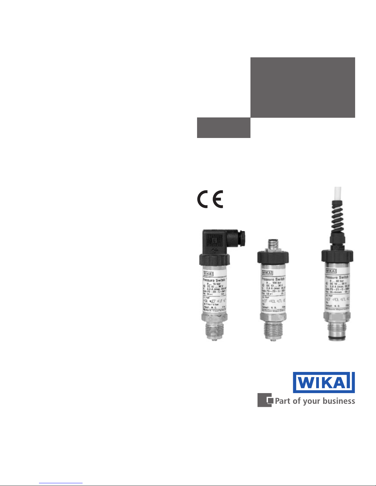
PS-20, PS-21
Electronic pressure switch
Elektronischer Druckschalter
Pressostat électronique
PS-21
PS-20
Current terms and conditions apply.
Details are available on ...
Es gelten unsere aktuellen Verkaufsund Lieferbedingungen siehe unter ...
Toute commande est assujettie à nos conditions
de ventes et de fournitures dans leur dernière
version en vigueur, voir sous ...
www.wika.com
PS-20
Page 2

2301300.07 EN/DE/FR 12/2017
2
WIKA Operating instructions / Betriebsanleitung / Mode d'emploi PS-20, PS-21
Contents Page 3-15 EN
1. Important details for your information
2. A quick overview for you
3. Signs, symbols and abbreviations
4. Function
5. For your safety
6. Packaging
7. Starting, operation
8. Maintenance, accessories
9. Trouble shooting
10. Storage, disposal
Programming 41
Configuration Software EasySwitch 42
Inhalt Seite 16-28 DE
1. Wichtiges zu Ihrer Information
2. Der schnelle Überblick für Sie
3. Zeichenerklärungen, Abkürzungen
4. Funktion
5. Zu Ihrer Sicherheit
6. Verpackung
7. Inbetriebnahme, Betrieb
8. Wartung, Zubehör
9. Störbeseitigung
10. Lagerung, Entsorgung
Programmierung 41
Konfigurationssoftware EasySwitch 42
Contenu Page 29-41 FR
1. Informations inportantes
2. Aperçu rapide
3. Explication des symboles,abréviations
4. Fonction
5. Pour votre sécurité
6. Emballage
7. Mise en service, exploitation
8. Entretien, accessoires
9. Elimination de perturbations
10. Stockage, mise au rebut
Programmation 41
Software de configuration EasySwitch 42
Contents / Inhalt / Contenu FREN DE
Page 3

2301300.07 EN/DE/FR 12/2017
3 WIKA Operating instructions / Betriebsanleitung / Mode d'emploi PS-20, PS-21
1. Important details for your information / 2. A quick overview for you
EN
1. Important details for your information
Read these operating instructions before installing and starting the pressure switch.
Keep the operating instructions in a place that is accessible to all users at any time.
The following installation and operating instructions have been compiled by us with great care but it is not
feasible to take all possible applications into consideration. These installation and operation instructions
should meet the needs of most pressure measurement applications. If questions remain regarding a specific
application, you can obtain further information:
■
Via our Internet address www.wika.de / www.wika.com
■
The product data sheet is designated as PE 81.28
■
Contact WIKA for additional technical support +49 9372 132-0
With special model number, e.g. PS-20000 or PS-21000, please note specifications in the delivery note. If the
serial number on the product label gets illegible (e.g. by mechanical damage or repainting), the retraceability
of the instrument is not possible any more.
WIKA pressure switches are carefully designed and manufactured using state-of-the-art technology. Every
component undergoes strict quality and environmental inspection before assembly and each instrument is
fully tested prior to shipment. Our environmental management system is certified to DIN EN ISO 14001.
Use of the product in accordance with the intended use PS-20, PS-21
Use the pressure switches to transform the pressure into an electrical signal.
Knowledge required
Install and start the pressure switch only if you are familiar with the relevant regulations and directives of your
country and if you have the qualification required. You have to be acquainted with the rules and regulations
on measurement and control technology and electric circuits. Depending on the operating conditions of your
application you have to have the corresponding knowledge, e.g. of aggressive media.
2. A quick overview for you
If you want to get a quick overview, read Chapters 3, 5, 7 and 10. There you will get some short safety
instructions and important information on your product and its starting. Read these chapters in any case.
Page 4
2301300.07 EN/DE/FR 12/2017
4
WIKA Operating instructions / Betriebsanleitung / Mode d'emploi PS-20, PS-21
3. Signs, symbols and abbreviations / 4. Function
GB
3. Abbreviations, signs and symbols
4. Function
PS-20: Pressure connection with internal diaphragm(standard version).
PS-21: Pressure connection with flush diaphragm for highly viscous or solids entrained media which might
clog the pressure port.
Function
The pressure prevailing within the application is transformed into a sensor signal through the deflection of
the diaphragm, which acts on the sensor element with the power supply fed to the transmitter. This electric
signal changes in proportion to the pressure. The electrical signal on the switching output is changed when
reaching the preset switching point.
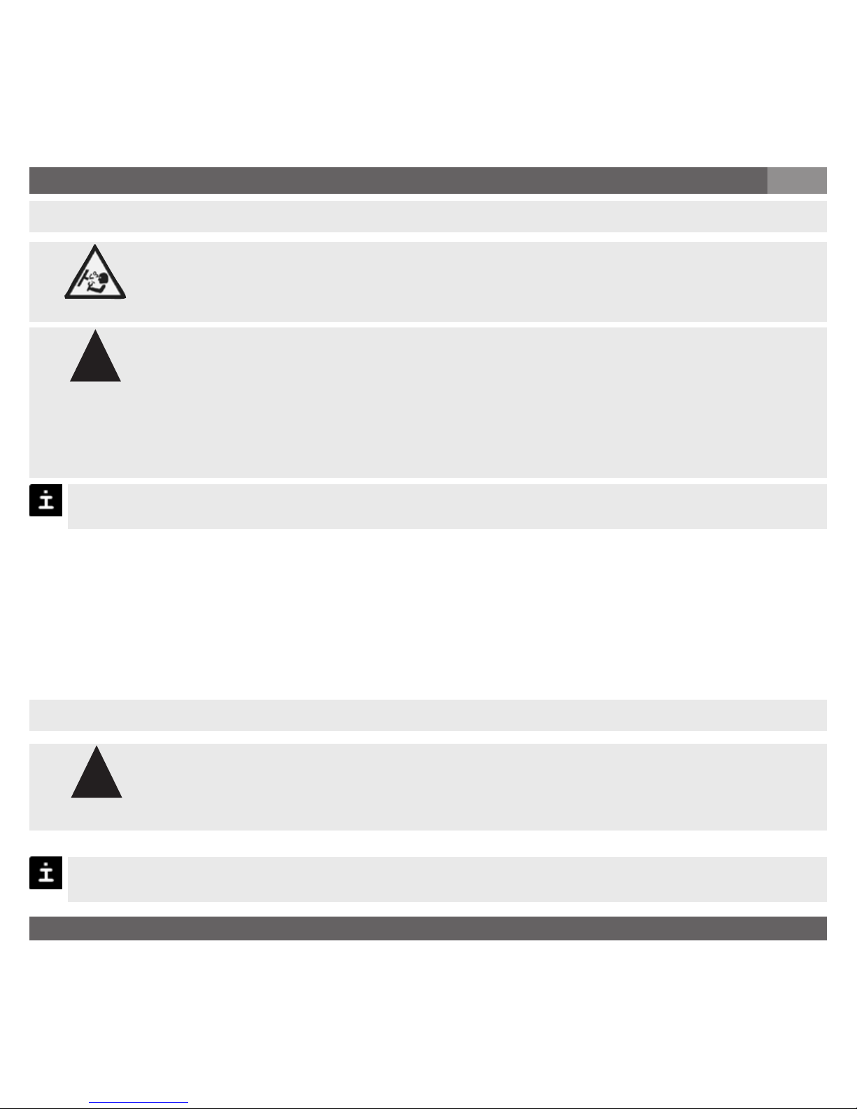
Potential danger of life or of
severe injuries.
Notice, important information,
malfunction.
The product complies with the
applicable European directives.
Potential danger of life or of
severe injuries due to catapulting
parts.
Potential danger of burns due to
hot surfaces.
!
Warning
Caution
Warning
Page 5

2301300.07 EN/DE/FR 12/2017
5 WIKA Operating instructions / Betriebsanleitung / Mode d'emploi PS-20, PS-21
5. For your safety
5. For your safety
GB
■
Select the appropriate pressure switch with regard to scale range, performance and
specific measurement conditions prior to installing and starting the instrument.
■
Observe the relevant national regulations and observe the applicable standards and
directives for special applications (e.g. with dangerous media such as acetylene,
flammable gases or liquids and toxic gases or liquids and with refrigeration plants or
compressors). If you do not observe the appropriate regulations, serious injuries and/or
damage can occur!
■
Open pressure connections only after the system is without pressure!
■
Please make sure that the pressure switch is only used within the overload threshold limit all the time!
■
Observe the ambient and working conditions outlined in section 7 „Technical data”.
■
Observe the technical data for the use of the pressure switch in connection with aggressive / corrosive
media and for the avoidance of mechanical hazards.
■
Ensure that the pressure switch is only operated in accordance with the provisions i.e. as described in
the following instructions.
■
Do not interfere with or change the pressure switch in any other way than described in these operating
instructions.
■
Remove the pressure switch from service and mark it to prevent it from being used again accidentally, if
it becomes damaged or unsafe for operation
■
Take precautions with regard to remaining media in removed pressure switches.Remaining media in the
pressure port may be hazardous or toxic!
■
Have repairs performed by the manufacturer only.
!
Warning
Page 6

2301300.07 EN/DE/FR 12/2017
6
WIKA Operating instructions / Betriebsanleitung / Mode d'emploi PS-20, PS-21
6. Packaging / 7. Starting, operation GB
6. Packaging
Has everything been supplied?
Check the scope of supply:
■
Completely assembled pressure switches; with flush version PS-20 including pre-assembled
sealings and protection cap.
■
Inspect the pressure switch for possible damage during transportation. Should there be any
obvious damage, inform the transport company and WIKA without delay.
■
Keep the packaging, as it offers optimal protection during transportation (e.g. changing installation
location, shipment for repair).
■
Ensure that the pressure connection thread and the connection contacts will not be damaged.
In order to protect the diaphragm, the pressure connection of the instrument PS-21 is provided with a special
protection cap.
■
Remove this protection cap only just before installing the pressure switch in order to prevent any
damage to the diaphragm or the thread.
■
Keep the protection cap of the pressure connection thread and the diaphragm for later storage or
transport.
■
Mount the protection cap when removing and transporting the instrument.
7. Starting, operation
Required tools: wrench (flats 27 or 41), screw driver
Diaphragm test for your safety
It is necessary that before starting the pressure transmitter you test the diaphragm visually, as this is a safetyrelevant component.
■
Pay attention to any liquid leaking out, for this points to a diaphragm damage.
■
Check the diaphragm visually for any damage (PS-21).
■
Use the pressure switch only if the diaphragm is undamaged.
■
Use the pressure switch only if it is in a faultless condition as far as the safety-relevant
features are concerned.
!
Warning
Page 7
2301300.07 EN/DE/FR 12/2017
7 WIKA Operating instructions / Betriebsanleitung / Mode d'emploi PS-20, PS-21
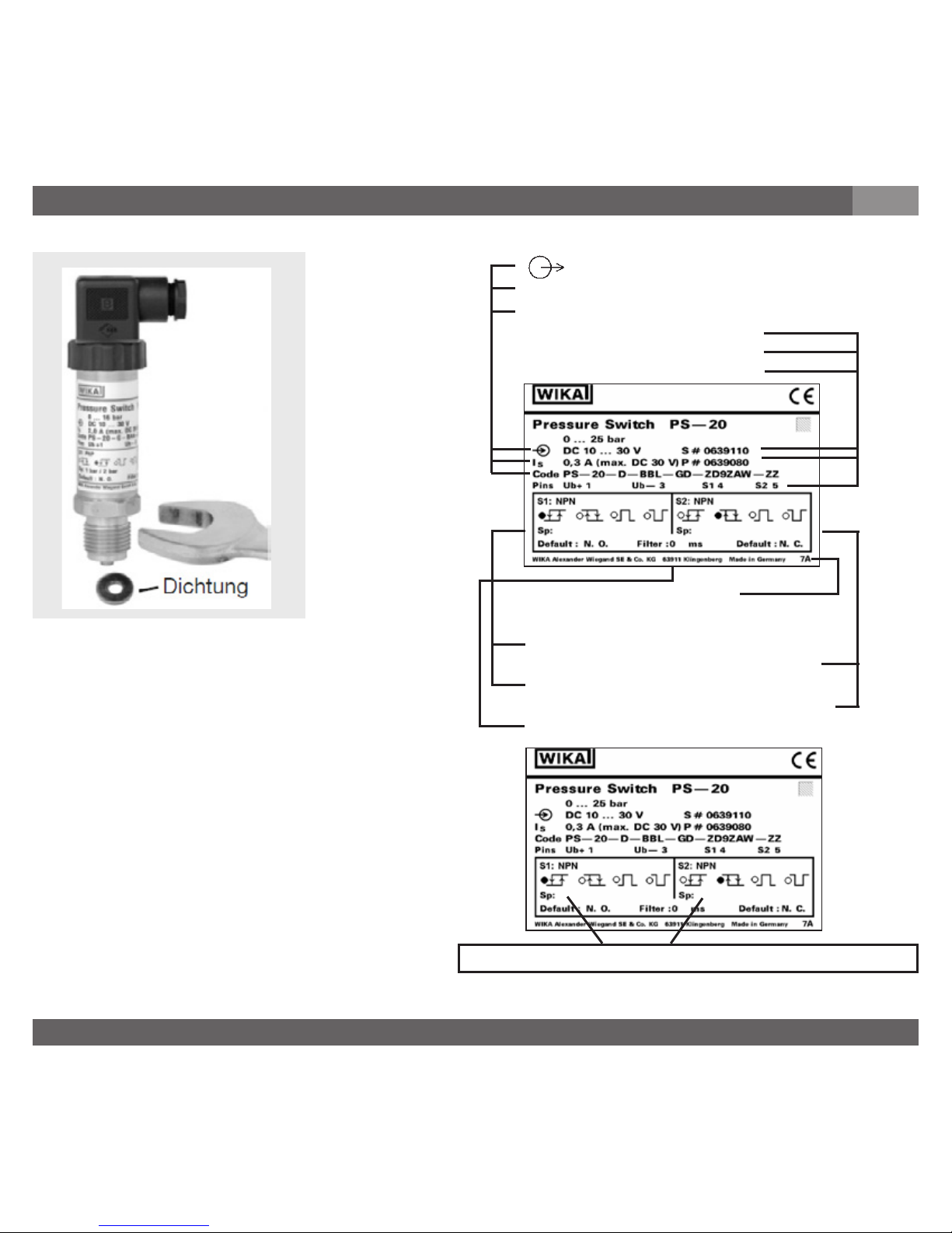
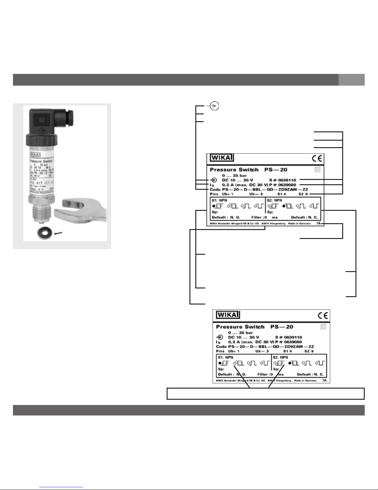
P #
S #
I
S
Code
7. Starting, operation
GB
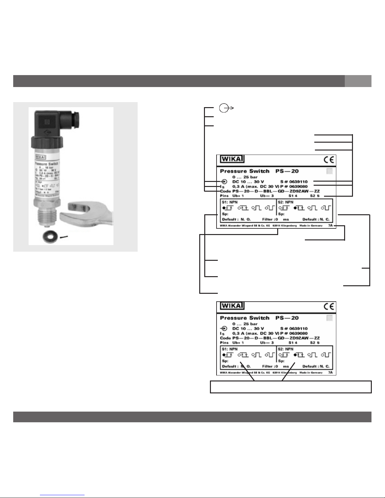
Sealing
Mechanical connection
Product label (example)
Fill in switching points with a waterproof pen
Signal
Switching current
Order code
Serial No.
Product No.
PIN assignment
Coded manufacturer date
Switching point configurations
S1 = making contact SP with hysteresis
S2 = breaking contact SP with hysteresis
S1 = default: normally open
S2 = default: normally closed
Filter = attenuation of pressure spikes
Page 8

2301300.07 EN/DE/FR 12/2017
8
WIKA Operating instructions / Betriebsanleitung / Mode d'emploi PS-20, PS-21
■
Connect the instrument to earth via the pressure connection.
■
The instrument must be grounded via the process connection!
■
The power supply for the pressure transmitter must be made via an energy-limited electrical circuit in
accordance with section 9.3 of UL/EN/IEC 61010-1, or an LPS to UL/EN/IEC 60950-1, or class 2 in
accordance with UL1310/UL1585 (NEC or CEC). The power supply must be suitable for operation above
2,000 m should the pressure transmitter be used at this altitude.
■
Ingress protection per IEC 60529 (The ingress protection classes specified only apply while the pressure
switch is connected with female connectors that provide the corresponding ingress protection).
■
Ensure that the cable diameter you select fits to the cable gland of the connector. Ensure that the cable
gland of the mounted connector is positioned correctly and that the sealings are available and undamaged. Tighten the threaded connection and check the correct position of the sealings in order to ensure the
ingress protection.
■
Please make sure that the ends of cables with flying leads do not allow any ingress of moisture.
■
Don’t connect lines within a building which are longer than 30 m, or leave the building (including lines of
outdoor installations).
Electrical connection
7. Starting, operation
GB
■
Remove the protection cap only just before installation and absolutely avoid any damage to the
diaphragm during installation as well (PS-21).
■
For Model PS-20 you have to provide for a sealing element; exceptions are instruments with self-sealing
threads (e.g. NPT thread). For Model PS-21 the sealing ring is included in delivery.
■
Please refer to our data sheet “Pressure gauge sealing washers AC 09.08” in WIKA’s product catalog
Pressure and Temperature Measurement or our website www.wika.de for details about sealing washers.
■
When mounting the instrument, ensure that the sealing faces of the instrument and the measuring point
are clean and undamaged.
■
Screw in or unscrew the instrument only via the flats using a suitable tool and the prescribed torque. The
appropriate torque depends on the dimension of the pressure connection and on the sealing element
used (form/material). Do not use the case as working surface for screwing in or unscrewing the instrument.
■
When screwing the switch in, ensure that the threads are not jammed.
■
For tapped holes and welding sockets please see Technical Information IN 00.14 for download at www.
wika.de-Service
Page 9
2301300.07 EN/DE/FR 12/2017
9 WIKA Operating instructions / Betriebsanleitung / Mode d'emploi PS-20, PS-21
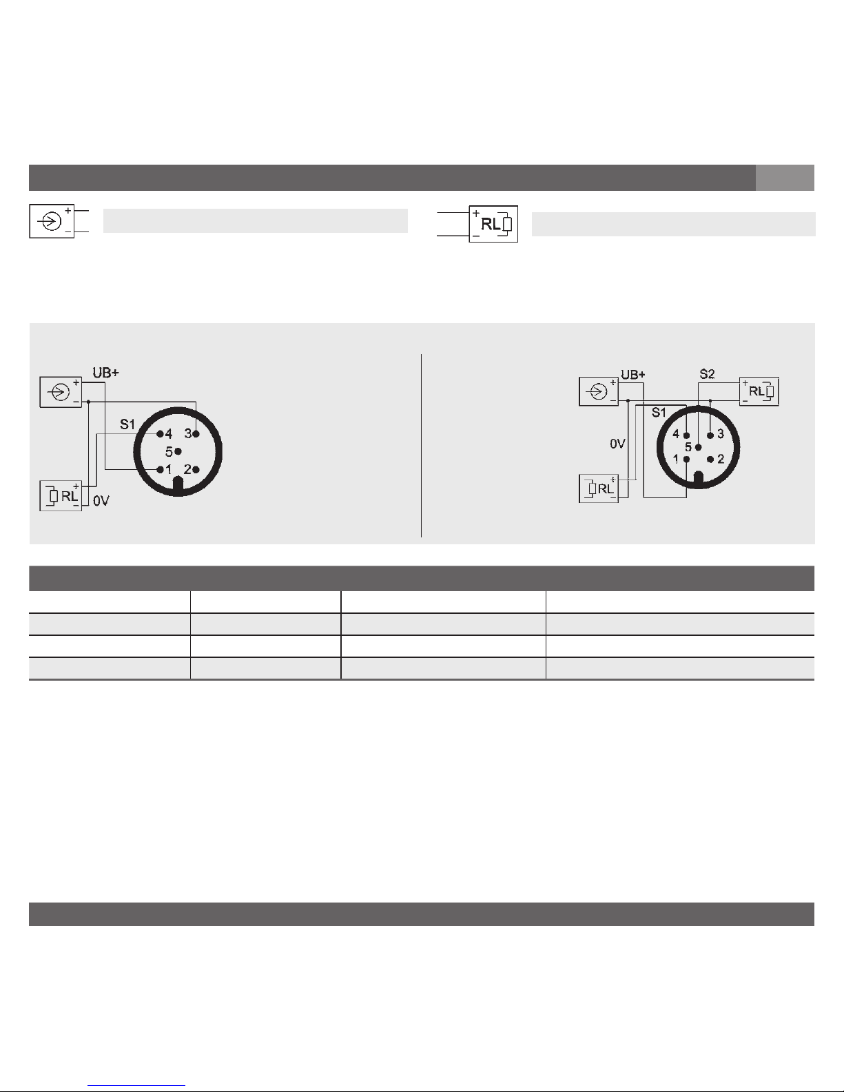
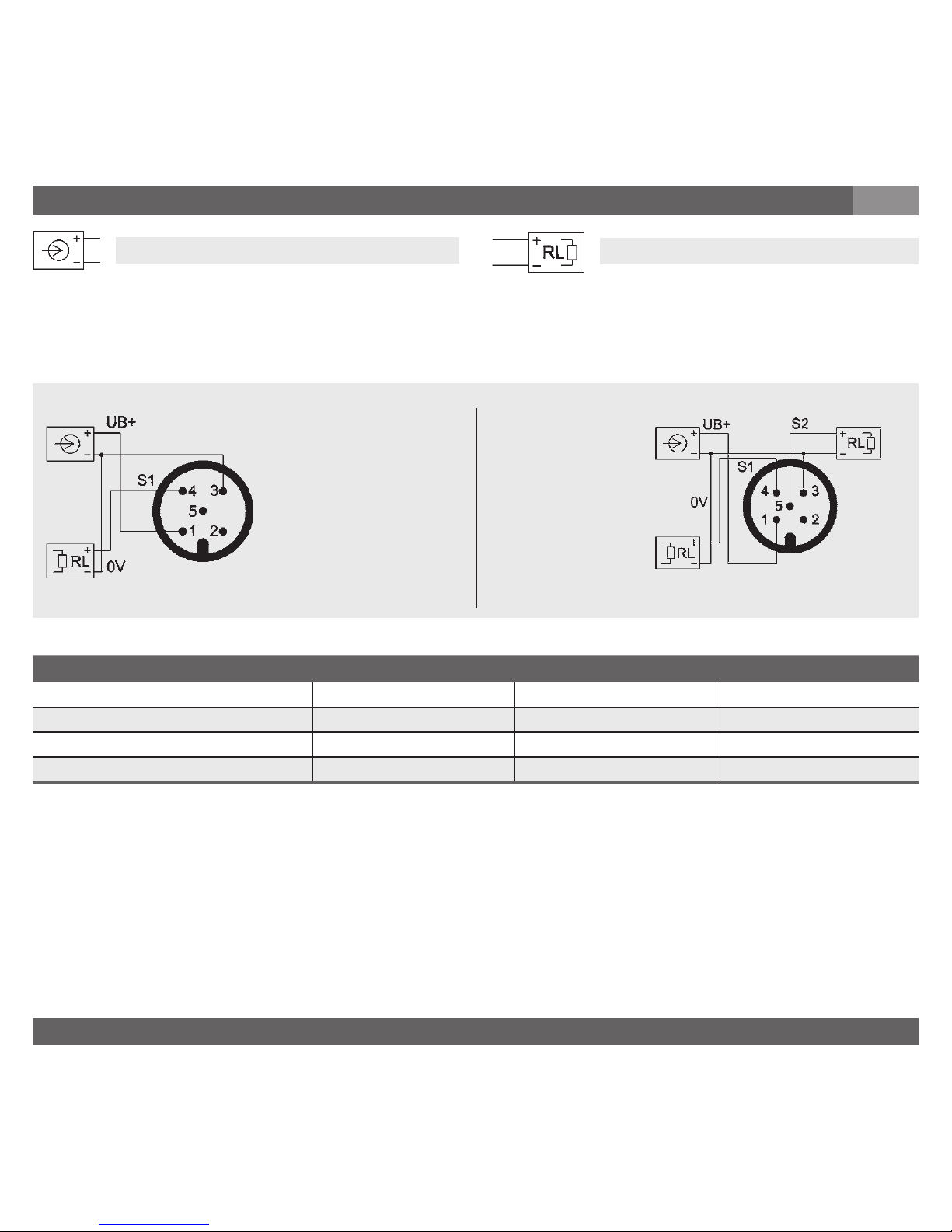
configuration flying leads L-connector circular connector M12x1
Power supply (UB+) brown 1 1
0 V green 2 3
Switch 1 (S1) white 3 4
Switch 2 (S2) yellow - 5
7. Starting, operation
GB
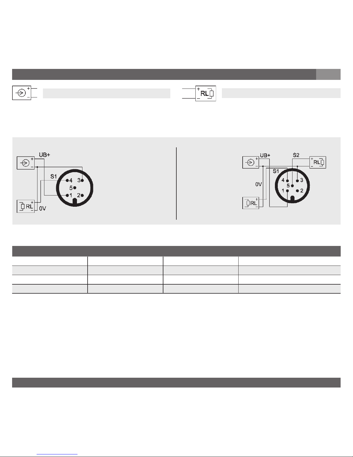
Power supply
UB+ Positive supply / measurement connection S1 Switching output 1
OV Negative supply / measurement connection S2 Switching output 2
US+ Positive switching voltage supply connection
Load
A (PNP)
C (PNP/PNP)
Circular connector M12x1, 5-pin
Page 10
2301300.07 EN/DE/FR 12/2017
10
WIKA Operating instructions / Betriebsanleitung / Mode d'emploi PS-20, PS-21
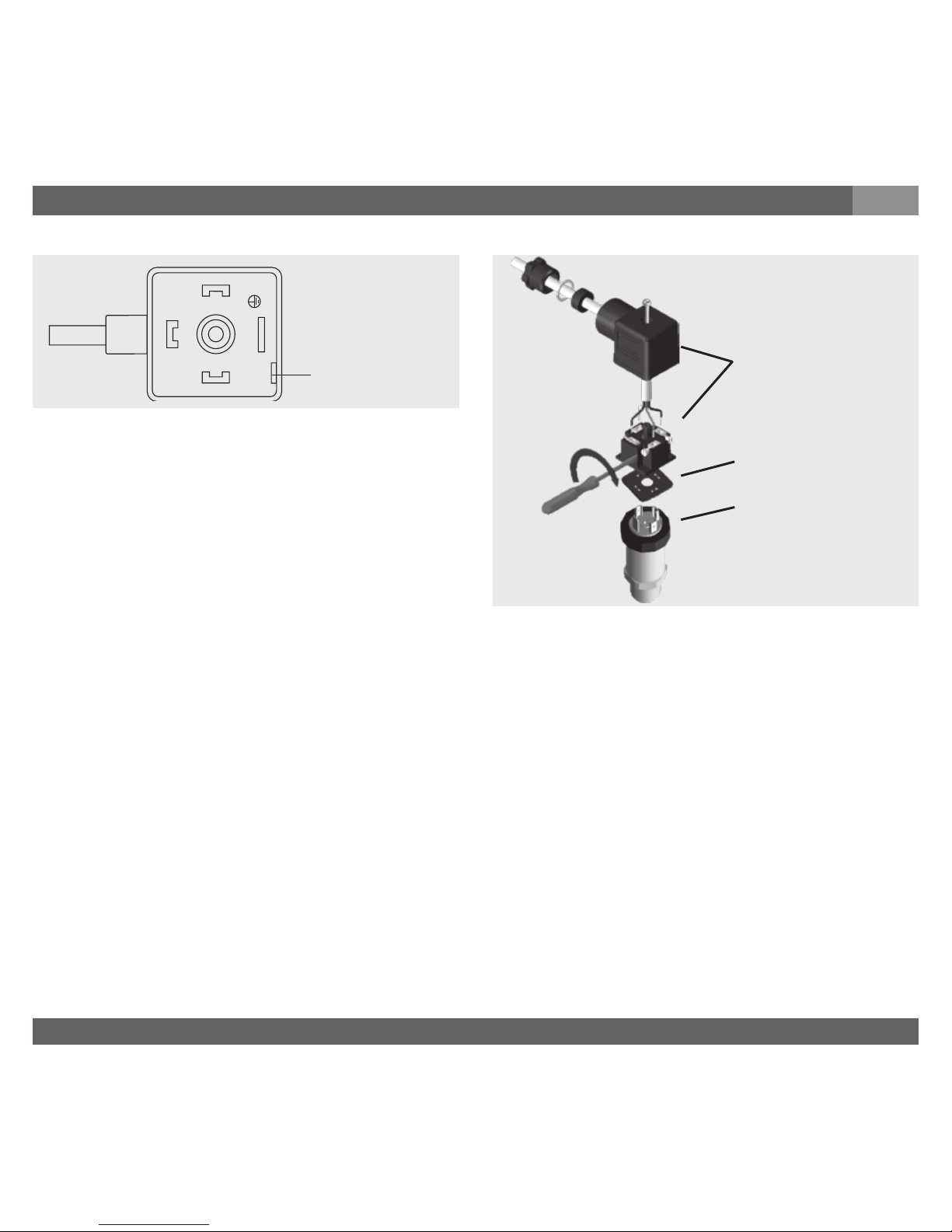
(D) Mounting hole
1. Loosen the screw (1).
2. Loosen the cable gland (2).
3. Pull the angle housing (5), with the
terminal block (6) inside, away from the
instrument.
4. Using the head of a small screwdriver in
the mounting hole (D), lever the terminal
block (6) out of the angle housing (5).
In order not to damage the sealing of the angle housing, do not try to push the terminal block (6) out
using the screw hole (1) or the cable gland (2).
5. Ensure that the conductor outer diameter you select is matched to the angle housing’s cable gland. Slide
the cable through the cable gland nut (2), washer (3), gland seal (4) and angle housing (5).
6. Connect the flying leads to the screw terminals on the terminal block (6) in accordance with the
pin-assignment drawing.
7. Press the terminal block (6) back into the angle housing (5).
8. Tighten the cable gland (2) around the cable. Make sure that the sealing isn’t damaged and that the
cable gland and seals are assembled correctly in order to ensure ingress protection.
9. Place the flat, square gasket over the connection pins on the top of the instrument housing.
10. Slide the terminal block (6) onto the connection pins.
11. Secure the angle housing (5) and terminal block (6) to the instrument with the screw (1).
Assembly of L-connector DIN EN 175301-803
(6)
(5)
(1)
(2)
(3)
(4)
Clamping nut,
Male connector,
Case with
pressure connection
Sealing
Female connector
7. Starting, operation
GB
Page 11
2301300.07 EN/DE/FR 12/2017
11 WIKA Operating instructions / Betriebsanleitung / Mode d'emploi PS-20, PS-21
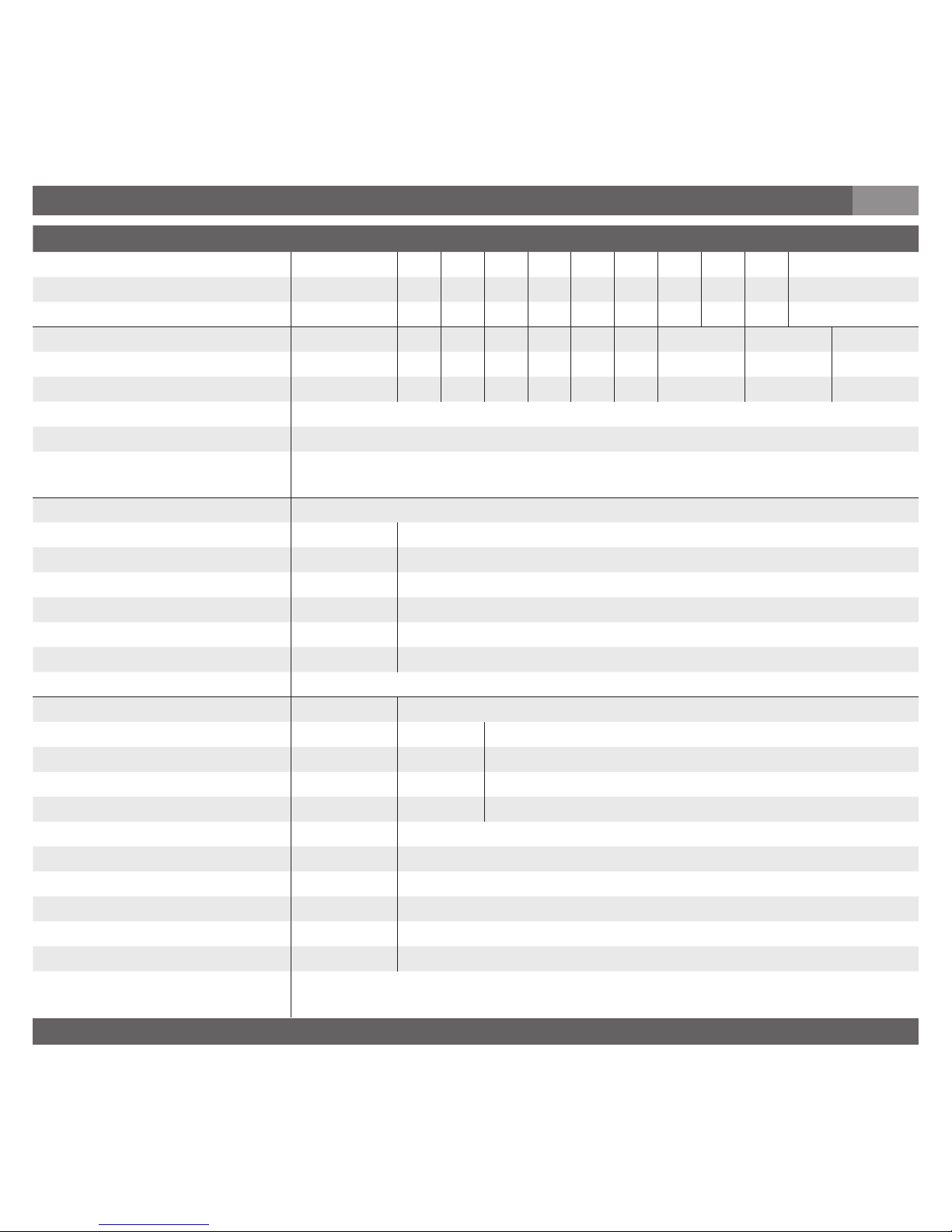
Specifications Model PS-20 / PS-21
Pressure ranges bar
0.25 0.4 0.6 1 1.6 2.5 4 6 10 16
Over pressure safety bar
2 2 4 5 10 10 17 35 35 80
Burst pressure bar
2.4 2.4 4.8 6 12 12 20.5 42 42 96
Pressure ranges bar
25 40 60 100 160 250 400 600 1000
1)
Over pressure safety bar
50 80 120 200 320 500 800 1200 1500
Burst pressure bar
96 400 550 800 1000 1200 1700
2)
2400
2)
3000
{Vacuum, gauge pressure, compound range, absolute pressure are available}
1)
Only model PS-20.
2)
For model PS-21: The value specific in the table applies only when sealing is
realised with the sealing ring underneath the hex. Otherwise max. 1500. bar applies.
Materials
Wetted parts
Model PS-20
*)
Stainless steel
Model PS-21 Stainless steel {Hastelloy}
O-Ring: NBR {FPM/FKM or EPDM}
Case Stainless steel
Internal transmission fluid 3) Synthetic oil {Halocarbon oil for oxygen applications}
3) Not for model PS-20 with pressure ranges > 25 bar.
Power supply U
B
UB in VDC 10 (12) < UB ≤ 30 (using the programming module)
Type of switch A C
Number of switching points 1 2
Switching current (max. DC 30 V) 4 2
Mode of connection PNP PNP/PNP
Switch
Function NC or NO
■
Adjustment of switching points % of span 0 ... 100
■
Switching hysteresis % of span 1 ... 99
■
Switching window % of span 0 ... 100
■
Default values low / high are set at latest 20 ms after the instrument has been switched on
4)
4)
This guarantees a clear definition of the switching state, when the instrument is
switching on within the hysteresis pressure range.
7. Starting, operation
GB
Page 12

2301300.07 EN/DE/FR 12/2017
12
WIKA Operating instructions / Betriebsanleitung / Mode d'emploi PS-20, PS-21
Specifications Model PS-20 / PS-21
■
Damping ms 0 ... 500
■
Manufacturer‘s settings when selected via the software the manufacturer‘s values are activated
■
Switching time ms < 6
Insulation voltage VDC 500
Accuracy adjustment of switching
points
6)
% of span ≤ 0.5 (BFSL)
≤ 1.0
5)
5) Including non-linearity, hysteresis, zero point and full scale error (corresponds to
error of measurement per IEC 61298-2).
Adjusted in vertical mounting position with lower pressure connection.
6) In individual cases equipment exposed to strong electromagnetic fields with
frequencies up to 2.7 GHz may show increased measurement errors of up to 3 %.
To avoid such influences on the measurement signal do not operate the equipment
in proximity to strong transmitters or radio installations, or use suitable sheath
current filters.
Non-repeatability % of span ≤ 0.25
1-year stability % of span ≤ 0.2 (at reference conditions)
Permissible temperature ranges
■
Medium *) -30 … +100 °C {-40 … +125 °C} -22 ... +212 °F {-40 … +257 °F}
■
Ambient -20 ... +80 °C -4 ... +176 °F
■
Storage -40 ... +100 °C -40 ... +212 °F
Compensated temp. range 0 ... +80 °C +32 ... +176 °F
Temperature coefficients in
compensated temp. range
■
Mean TC of zero % of span ≤ 1.0
■
Mean TC of span % of span ≤ 1.0
CE- conformitiy
■
Pressure equipment directive
■
EMC directive
EN 61326 Emission (Group 1, Class B) and Immunity (industrial
locations)
7. Starting, operation
GB
Page 13
2301300.07 EN/DE/FR 12/2017
13 WIKA Operating instructions / Betriebsanleitung / Mode d'emploi PS-20, PS-21
Specifications Model PS-20 / PS-21
Shock resistance g 500 according to IEC 60068-2-27 (mechanical shock)
Vibration resistance g 15 according to IEC 60068-2-26 (vibration under resonance)
Wiring protection
■
Short-circuit proofness Sig+ towards U
B-
■
Reverse polarity protection UB+ towards U
B-
■
Overvoltage protection VDC 36
Weight kg Approx. 0.2
*) In an oxygen version model PS-21 is not available. In an oxygen version model PS-20 is only available with media temperatures between -4 … +140 °F / -20 … +60 °C and
using stainless steel or Elgiloy® wetted parts.
{ } Items in curved brackets are optional extras for additional price.
Functional test
■
Open pressure connections only after the system is without pressure!
■
Observe the ambient and working conditions outlined in section 7 „Technical data".
■
Please make sure that the pressure switch is only used within the overload threshold
limit at all times!
When touching the pressure switch, keep in mind that the surfaces of the instrument
components might get hot during operation.
When designing your plant, take into account that the stated values (e.g.burst pressure, over pressure
safety) apply depending on the material, thread and sealing element used.
7. Starting, operation
GB
Warning
Caution
Page 14
2301300.07 EN/DE/FR 12/2017
14
WIKA Operating instructions / Betriebsanleitung / Mode d'emploi PS-20, PS-21
8. Maintenance, accessories / 9. Trouble shooting
GB
8. Maintenance, accessories
Accessories
For details about the accessories (e. g. connectors), please refer to WIKA‘s price list, WIKA‘s product catalog
on CD or or contact our sales department.
9. Trouble shooting
Open pressure connections only after the system is without pressure!
■
WIKA pressure switches require no maintenance.
■
Have repairs performed by the manufacturer only.
Do not insert any pointed or hard objects into the pressure port for cleaning to prevent damage to the
diaphragm of the pressure connection.
■
Take precautions with regard to remaining media in removed pressure switches.
Remaining media in the pressure port may be hazardous or toxic!
■
Remove the pressure switch from service and mark it to prevent it from being used
again accidentally, if it becomes damaged or unsafe for operation.
■
Have repairs performed by the manufacturer only.
Warning
!
Warning
Page 15

2301300.07 EN/DE/FR 12/2017
15 WIKA Operating instructions / Betriebsanleitung / Mode d'emploi PS-20, PS-21
If the problem persists, contact our sales department.
USA, Canada
If the problem continues, contact WIKA or an authorized agent for assistance. If the pressure switch must be
returned obtain an RMA (return material authorization) number and shipping instructions from the place of
purchase. Be sure to include detailed information about the problem. Pressure switches received by WIKA
without a valid RMA number will not be accepted.
Process material certificate (Contamination declaration for returned goods)
Purge / clean dismounted instruments before returning them in order to protect our employees and the
environment from any hazard caused by adherent remaining media.
Service of instruments can only take place safely when a Product Return Form has been submitted and
fully filled-in. This Return Form contains information on all materials with which the instrument has come into
contact, either through installation, test purposes, or cleaning. You can find the Product Return Form on our
internet site (www.wika.de / www.wika.com).
9. Trouble shooting / 10. Storage, disposal
GB
10. Storage, disposal
When storing or disposing of the pressure switch, take precautions with regard to remaining media in removed pressure switches. We recommend cleaning the switch properly
and carefully. Remaining media in the pressure port may be hazardous or toxic!
Mount the protection cap when storing the pressure transmitter in order to prevent any damage to the
diaphragm (PS-21).
Dispose of instrument components and packaging materials in accordance with the respective waste
treatment and disposal regulations of the region or country to which the instrument is supplied.
Storage
Disposal
WIKA reserves the right to alter these technical specifications.
!
Warning
Page 16

2301300.07 EN/DE/FR 12/2017
16
WIKA Operating instructions / Betriebsanleitung / Mode d'emploi PS-20, PS-21
1. Wichiges zu Ihrer Information / 2. Schneller Überblick
D
1. Wichtiges zu Ihrer Information
Lesen Sie diese Betriebsanleitung vor Montage und Inbetriebnahme des Druckschalters.
Bewahren Sie die Betriebsanleitung an einem für alle Benutzer jederzeit zugänglichen Ort auf.
Die nachfolgenden Einbau- und Betriebshinweise haben wir mit Sorgfalt zusammengestellt. Es ist jedoch
nicht möglich, alle erdenklichen Anwendungsfälle zu berücksichtigen. Sollten Sie Hinweise für Ihre spezielle
Aufgabenstellung vermissen, können Sie hier weitere Informationen finden:
■
Über unsere Internet-Adresse www.wika.de / www.wika.com
■
Die Bezeichnung des zugehörigen Datenblattes ist PE 81.28
■
Anwendungsberater: +49 9372 132-0
Bei Sondertypennummer, z.B. PS-20000 oder PS-21000, beachten Sie die Spezifikationen gemäß Lieferschein. Wird die Seriennummer auf dem Typenschild unleserlich (z. B. durch mechanische Beschädigung
oder Übermalen), ist eine Rückverfolgbarkeit nicht mehr möglich.
Die in der Betriebsanleitung beschriebenen WIKA-Druckschalter werden nach den neuesten Erkenntnissen
konstruiert und gefertigt. Alle Komponenten unterliegen während der Fertigung strengen Qualitäts- und
Umweltkriterien. Unser Umweltmanagementsystem ist nach DIN EN ISO 14001 zertifiziert.
Bestimmungsgemäße Produktverwendung PS-20, PS-21
Verwenden Sie den Druckschalter, um Druck in ein elektrisches Signal zu wandeln und bei Erreichen eines
eingestellten Schaltpunktes einen elektrischen Signalwechsel am Schaltausgang zu bewirken.
Ihre erforderlichen Kenntnisse
Montieren und nehmen Sie den Druckschalter nur in Betrieb, wenn Sie mit den zutreffenden landesspezifischen Richtlinien vertraut sind und die entsprechende Qualifikation besitzen. Sie müssen mit den Kenntnissen von Mess- und Regeltechnik sowie elektrischen Stromkreisen vertraut sein. Je nach Einsatzbedingung
müssen Sie über entsprechendes Wissen verfügen, z. B. über agressive Medien.
2. Der schnelle Überblick für Sie
Wollen Sie sich einen schnellen Überblick verschaffen, lesen Sie Kapitel 3, 5, 7 und 10. Dort erhalten Sie
kurze Hinweise zu Ihrer Sicherheit und wichtige Informationen über Ihr Produkt und zur Inbetriebnahme.
Lesen Sie diese unbedingt.
Page 17
2301300.07 EN/DE/FR 12/2017
17 WIKA Operating instructions / Betriebsanleitung / Mode d'emploi PS-20, PS-21
3. Zeichenerklärungen, Abkürzungen / 4. Funktion
D
4. Funktion
PS-20: Druckanschluss mit innenliegender Membran (Standardausführung).
PS-21: Druckanschluss mit frontbündiger Membrane für hochviskose oder kristallisierende Medien, die
die Bohrung des Druckanschlusses zusetzen können.
Funktion
Mittels Sensorelement und unter Zuführung von Hilfsenergie wird über die Verformung einer Membran der
anstehende Druck in Ihrer Anwendung in ein verstärktes Sensorsignal umgewandelt. Dieses elektrische
Signal verändert sich proportional zum Druck. Bei Erreichen eines eingestellten Schaltpunktes erfolgt ein
elektrischer Signalwechsel am Schaltausgang.
3. Zeichenerklärungen, Abkürzungen
Mögliche Gefahr für Ihr Leben
oder schwerer Verletzungen.
Hinweis, wichtige Information,
Funktionsstörung.
Das Produkt stimmt mit den
zutreffenden europäischen
Richtlinien überein.
Mögliche Gefahr für Ihr Leben
oder schwerer Verletzungen
durch wegschleudernde Teile.
Mögliche Gefahr von
Verbrennungen durch heisse
Oberflächen.
!
Warnung
Vorsicht
Warnung
Page 18

2301300.07 EN/DE/FR 12/2017
18
WIKA Operating instructions / Betriebsanleitung / Mode d'emploi PS-20, PS-21
5. Zu Ihrer Sicherheit
D
5. Zu Ihrer Sicherheit
■
Wählen Sie den richtigen Druckschalter hinsichtlich Messbereich, Ausführung und spezifischen Messbedingungen vor Montage oder Inbetriebnahme.
■
Halten Sie die entsprechenden landesspezifischen Vorschriften ein und beachten Sie bei
speziellen Anwendungen die geltenden Normen und Richtlinien (z. B. bei gefährlichen
Messstoffen wie Acetylen, brennbaren oder giftigen Stoffen sowie bei Kälteanlagen und
Kompressoren). Wenn Sie die entsprechenden Vorschriften nicht beachten, können
schwere Körperverletzungen und Sachschäden entstehen!
■
Öffnen Sie Anschlüsse nur im drucklosen Zustand!
■
Betreiben Sie den Druckschalter immer innerhalb des Überlastgrenzbereiches!
■
Beachten Sie die Betriebsparameter gemäß Punkt 7 „Technische Daten“.
■
Beachten Sie die Technischen Daten zur Verwendung des Druckschalters in Verbindung
mit agressiven / korrosiven Medien und zur Vermeidung von mechanischen Gefährdungen.
■
Stellen Sie sicher, dass der Druckschalter nur bestimmungsgemäß -also wie in der
folgenden Anleitung beschrieben- betrieben wird.
■
Unterlassen Sie unzulässige Eingriffe und Änderungen am Druckschalter, welche nicht in
dieser Betriebsanleitung beschrieben sind.
■
Setzen Sie den Druckschalter außer Betrieb und schützen Sie ihn gegen versehentliche
Inbetriebnahme, wenn Sie Störungen nicht beseitigen können.
■
Ergreifen Sie Vorsichtsmaßnahmen für Messstoffreste in ausgebauten Druckschaltern.
Messstoffreste können zur Gefährdung von Menschen, Umwelt und Einrichtung führen!
■
Lassen Sie Reparaturen nur vom Hersteller durchführen
!
Warnung
Page 19

2301300.07 EN/DE/FR 12/2017
19 WIKA Operating instructions / Betriebsanleitung / Mode d'emploi PS-20, PS-21
6. Verpackung
Überprüfen Sie den Lieferumfang:
■
Komplett montierte Druckschalter; bei frontbündiger Ausführung PS-21 mit vormontierten Dichtungen und Schutzkappe.
■
Untersuchen Sie den Druckschalter auf eventuell entstandene Transportschäden. Sind offensichtlich Schäden vorhanden, teilen Sie dies dem Transportunternehmen und WIKA unverzüglich mit.
■
Bewahren Sie die Verpackung auf, denn diese bietet bei einem Transport einen optimalen Schutz
(z. B. wechselnder Einbauort, Reparatursendung).
■
Achten sie darauf, dass das Druckanschluss-Gewinde und die Anschlusskontakte nicht beschädigt
werden.
Wurde alles geliefert?
6. Verpackung / 7. Inbetriebnahme, Betrieb
D
7. Inbetriebnahme, Betrieb
Es ist erforderlich, dass Sie vor Inbetriebnahme des Druckmessgerätes die Membran optisch prüfen, denn
sie ist ein sicherheitsrelevantes Teil.
Benötigtes Werkzeug: Maulschlüssel SW 27 und SW 41, Schraubendreher
■
Achten Sie auf auslaufende Flüssigkeit, denn sie ist ein Hinweis auf eineMembranbeschädigung.
■
Prüfen Sie die Membran optisch auf Beschädigung (PS-21).
■
Setzen Sie das Druckschalter nur ein, wenn die Membran unbeschädigt ist.
■
Setzen Sie das Druckschalter nur in sicherheitstechnisch einwandfreiem Zustand ein.
Membran-Prüfung zu Ihrer Sicherheit
Zum Schutz der Membran ist der Druckanschluss des Gerätes PS-21 mit einer speziellen Schutzkappe
versehen.
■
Entfernen Sie diese Schutzkappe erst kurz vor dem Einbau, damit die Membran bzw.das Druckanschluss-Gewinde nicht beschädigt wird.
■
Bewahren Sie die Schutzkappe des Druckanschluss-Gewindes und der Membran zur späteren
Lagerung oder Transport auf.
■
Montieren Sie die Schutzkappe bei Ausbau und Transport des Gerätes.
!
Warnung
Page 20
2301300.07 EN/DE/FR 12/2017
20
WIKA Operating instructions / Betriebsanleitung / Mode d'emploi PS-20, PS-21
7. Inbetriebnahme, Betrieb
D
Montage mechanischer Anschluss
Signal
Schaltstrom
Bestellcode
Serien-Nr.
Erzeugnis-Nr.
Anschlussbelegung
Typenschild (Beispiel)
P #
S #
I
S
Codiertes Herstelldatum
Schaltpunkteinstellungen
S1 = Schließer mit Hysterese
S2 = Öffner mit Hysterese
S1 = Grundeinstellung: offen
S2 = Grundeinstellung: geschlossen
Filter = Dämpfung v. Druckspitzen
Schaltpunkte mit einem wasserfesten Stift eintragen!
Code
Page 21

2301300.07 EN/DE/FR 12/2017
21 WIKA Operating instructions / Betriebsanleitung / Mode d'emploi PS-20, PS-21
7. Inbetriebnahme, Betrieb
D
Montage elektrischer Anschluss
■
Das Gerät über den Prozessanschluss erden.
■
Die Versorgung des Druckmessumformers muss durch einen energiebegrenzten Stromkreis
gemäß 9.3 der UL/EN/IEC 61010-1 oder LPS gemäß UL/EN/IEC 60950-1 oder Class 2 gemäß
UL1310/UL1585 (NEC oder CEC) erfolgen. Die Stromversorgung muss für den Betrieb oberhalb
2.000 m geeignet sein, falls der Druckmessumformer ab dieser Höhe verwendet wird.
■
Schutzart IP nach IEC 60529. (Die angegebenen Schutzarten gelten nur im gesteckten Zustand
mit Leitungsteckern (Buchsen) entsprechender Schutzart).
■
Wählen Sie den Kabeldurchmesser passend zur Kabeldurchführung des Steckers. Achten Sie
darauf, dass die Kabelverschraubung des montierten Steckers korrekt sitzt und dass die Dichtungen vorhanden und nicht beschädigt sind. Ziehen Sie die Verschraubung fest und überprüfen Sie
den korrekten Sitz der Dichtungen, um die Schutzart zu gewährleisten.
■
Stellen Sie bei Kabelausgängen sicher, dass am Ende des Kabels keine Feuchtigkeit eintritt.
■
Keine Leitungen anschließen, die innerhalb eines Gebäudes länger als 30 m sind oder das
Gebäude verlassen (einschließlich der Leitungen von Außeninstallationen).
■
Entfernen Sie die Schutzkappe erst kurz vor dem Einbau und achten Sie unbedingt darauf, dass
die Membran auch während des Einbaus nicht beschädigt wird (PS-21).
■
Bei Typ PS-20 müssen Sie eine Dichtung vorsehen; Ausnahme sind Geräte mit selbstdichtendem
Gewinde (z. B. NPT-Gewinde). Bei Typ PS-21 ist der Dichtring im Lieferumfang enthalten.
■
Hinweise zu Dichtungen entnehmen Sie bitte unserer Information “Zubehör Dichtungen AC 09.08” im
Gesamtkatalog Druck- und Temperaturmesstechnik oder unserer Internet-Seite unter www.wika.de.
■
Achten Sie bei der Montage auf saubere und unbeschädigte Dichtflächen am Gerät und Messstelle.
■
Schrauben Sie das Gerät nur über die Schlüsselflächen mit einem geeigneten Werkzeug und
dem vorgeschriebenen Drehmoment ein bzw. aus. Das richtige Drehmoment ist abhängig von der
Dimension des Druckanschlusses sowie der verwendeten Dichtung (Form/Werkstoff). Verwenden
Sie zum Ein- bzw. Ausschrauben nicht das Gehäuse als Angriffsfläche.
■
Beachten Sie beim Einschrauben, dass die Gewindegänge nicht verkantet werden.
■
Angaben zu Einschraublöchern und Einschweißstutzen entnehmen Sie bitte unserer Technischen
Information IN 00.14 unter www.wika.de-Service
Page 22
2301300.07 EN/DE/FR 12/2017
22
WIKA Operating instructions / Betriebsanleitung / Mode d'emploi PS-20, PS-21
Belegung Kabelausgang Winkelsteckverbinder Rundsteckverbinder M 12x1
Hilfsenergie (UB+) braun 1 1
0 V grün 2 3
Schaltausgang 1 (S1) weiß 3 4
Schaltausgang 2 (S2) gelb - 5
7. Inbetriebnahme, Betrieb
D
Last
Spannungsversorgung
UB+ Positiver Betriebsspannungversorgungsanschluss S1 Schaltausgang 1
OV Negativer Versorgungsanschluss S2 Schaltausgang 2
US+ Positiver Schaltspannungsversorgungsanschluss
A (PNP)
C (PNP/PNP)
Rundsteckverbinder M12x1, 5-polig
Page 23

2301300.07 EN/DE/FR 12/2017
23 WIKA Operating instructions / Betriebsanleitung / Mode d'emploi PS-20, PS-21
(D) Montageöffnung
Montage des Winkelsteckverbinder nach DIN EN 175301-803
(6)
(5)
(1)
(2)
(3)
(4)
Griffring,
Gerätestecker(Stift),
Gehäuse mit
Druckanschluss
Dichtung
Leitungsstecker
(Buchse)
1. Lösen Sie die Schraube (1).
2. Lösen Sie die Kabelverschraubung (2).
3. Ziehen Sie Winkelgehäuse (5)mit Klemm block (6) vom Gerät ab.
4. Hebeln Sie mit dem Schraubendreher in
die Montageöffnung (D), so dass Sie den
Klemmblock (6) aus dem Winkelgehäuse (5)
herausdrücken. Drücken Sie nicht den
Klemmblock (6) durch die Schraubenöffnung (1) bzw. Kabelverschraubung (2) heraus, sonst beschädi gen Sie die Dichtungen des Winkelgehäuses.
5. Wählen Sie den Leitungsaußendurchmesser passend zur Kabeldurchführung des Winkelgehäuses.
Schieben Sie das Kabel durch Kabelverschraubung (2), Ring (3), Dichtung (4) und Winkelgehäuse (5).
6. Schließen Sie die Kabelenden entsprechend der Belegungszeichnung in den Anschluß klemmen des
Klemmblocks (6) an.
7. Drücken Sie das Winkelgehäuse (5) auf den Klemmblock (6).
8. Verschrauben Sie das Kabel mit der Kabelverschraubung (2). Achten Sie darauf, dass die Dichtungen
unbeschädigt sind und Kabelverschraubung und Dichtungen korrekt sitzen, um die Schutzart zu gewähr leisten.
9. Legen Sie die quadratische Flachdichtung über die Anschlußpins im Gehäuse.
10. Schieben Sie den Klemmblock (6) auf die Anschlußpins im Gehäuse.
11. Verschrauben Sie mit der Schraube (1) das Winkelgehäuse (5) mit dem Klemmblock (6) im Gerät.
7. Inbetriebnahme, Betrieb
D
Page 24

2301300.07 EN/DE/FR 12/2017
24
WIKA Operating instructions / Betriebsanleitung / Mode d'emploi PS-20, PS-21
Technische Daten Typ PS-20 / PS-21
Messbereich bar
0,25 0,4 0,6 1 1,6 2,5 4 6 10 16
Überlastgrenze bar
2 2 4 5 10 10 17 35 35 80
Berstdruck bar
2,4 2,4 4,8 6 12 12 20,5 42 42 96
Messbereich bar
25 40 60 100 160 250 400 600 1000
1)
Überlastgrenze bar
50 80 120 200 320 500 800 1200 1500
Berstdruck bar
96 400 550 800 1000 1200 1700
2)
2400
2)
3000
{Unterdruck, Überdruck, +/- , sowie Absolutdruck erhältlich}
1) Nur für Typ PS-20 gültig.
2) Bei Typ PS-21: Der Tabellenwert gilt ausschließlich bei Abdichtung mittels Dichtring
unterhalb vom Sechskant. Andernfalls gilt max. 1500 bar.
Werkstoff
■
Messstoffberührte Teile
- Typ PS-20
*)
CrNi-Stahl
- Typ PS-21 CrNi-Stahl {Hastelloy}
O-Ring: NBR {FPM/FKM oder EPDM}
■
Gehäuse CrNi-Stahl
Interne Übertragungsflüssigkeit
3)
Synthetisches Öl {Halocarbonöl für Sauerstoff-Ausführungen}
3) Nicht vorhanden bei Typ PS-20 für Messbereiche > 25 bar.
Hilfsenergie U
B
UB in VDC 10 (12) < UB ≤ 30 (bei Einsatz des Programmiermoduls)
Schaltausgang Typ A C
Anzahl der Schaltausgänge 1 2
Schaltstrom (max. 30 VDC) 4 2
Anschlussart PNP PNP/PNP
Schaltausgang
■
Funktion Öffner oder Schließer
■
Abgleich der Ein- und
Auschaltpunkte
% d. Spanne 0 ... 100
■
Schalthysterese % d. Spanne 1 ... 99
■
Schaltfenster % d. Spanne 0 ... 100
7. Inbetriebnahme, Betrieb
D
Page 25

2301300.07 EN/DE/FR 12/2017
25 WIKA Operating instructions / Betriebsanleitung / Mode d'emploi PS-20, PS-21
Technische Daten Typ PS-20 / PS-21
Vorgabewerte low / high werden spätestens 20 ms nach Einschalten angenommen
4)
4) Dies gewährleistet beim Hochfahren im Hysteresebereich eine klare Definition des
Schaltzustandes,.
■
Dämpfung ms 0 ... 500
■
Werkseinstellungen Bei Aufruf über die Software werden die Ursprungswerte wieder aktiv
Schaltzeit ms ≤ 6
Isolationsspannung VDC 500
Abgleichgenauigkeit der Schalt-
punkte
6)
% d. Spanne ≤ 0,5 (BFSL)
≤ 1,0
5)
5) Einschließlich Nichtlinearität, Hysterese, Nullpunkt- und Endwertabweichung
(entspricht Messabweichung nach IEC 61298-2).
Kalibriert bei senkrechter Einbaulage Druckanschluss nach unten.
6) Bei Vorhandensein von starken elektromagnetischen Feldern im Frequenzbereich
< 2,7 GHz, kann es zu erhöhten Messfehlern bis zu 3 % der Spanne kommen. Die
Geräte nicht in der Nähe von starken elektromagnetischen Störquellen installieren
(z. B. Sendegeräte, Funkanlagen) oder ggf. Mantelstromfilter einsetzen.
Nichtwiederholbarkeit % d. Spanne ≤ 0,25
Stabilität pro Jahr % d. Spanne ≤ 0,2 (bei Referenzbedingungen)
Zulässige Temperaturbereiche
■
Messstoff *) °C -30 … +100 {-40 … +125}
■
Umgebung °C -20 ... +80
■
Lagerung °C -40 ... +100
Kompensierter Temperaturbereich
°C 0 ... +80
Temperaturkoeffizienten im
kompensierten Temperaturbereich
■
Mittlerer TK des Nullpunktes % d. Spanne ≤ 1,0
■
Mittlerer TK der Spanne % d. Spanne ≤ 1,0
7. Inbetriebnahme, Betrieb
D
Page 26

2301300.07 EN/DE/FR 12/2017
26
WIKA Operating instructions / Betriebsanleitung / Mode d'emploi PS-20, PS-21
Technische Daten Typ PS-20 / PS-21
CE- Kennzeichen
■
Druckgeräterichtlinie
■
EMV-Richtlinie
EN 61326 Emission (Gruppe 1, Klasse B) und Störfestigkeit (industriel-
ler Bereich)
Schockbelastbarkeit g 500 nach IEC 60068-2-27 (Schock mechanisch)
Vibrationsbelastbarkeit g 15 nach IEC 60068-2-6 (Vibration bei Resonanz)
Elektrische Schutzarten
■
Kurzschlussfestigkeit Sig+ gegen U
B-
■
Verpolschutz UB+ gegen U
B-
■
Überspannungsschutz VDC 36
Gewicht kg Ca. 0,2
*) In Sauerstoff-Ausführung ist Typ PS-21 nicht erhältlich. In Sauerstoff-Ausführung ist Typ PS-20 nur möglich mit Messstofftemperatur -20 … +60 °C und messstoffberührte
Teile in CrNi-Stahl oder Elgiloy®.
{ } Angaben in geschweiften Klammern beschreiben gegen Mehrpreis lieferbare Sonderheiten.
7. Inbetriebnahme, Betrieb
D
Funktionsprüfung
■
Öffnen Sie Anschlüsse nur im drucklosen Zustand!
■
Beachten Sie die Betriebsparameter gemäß Punkt 7„Technische Daten“.
■
Betreiben Sie den Druckschalter immer innerhalb des Überlastgrenzbereichs!
Beachten Sie beim Berühren des Druckschalters, dass die Oberflächen der Gerätekomponenten während des Betriebes heiß werden können.
Beachten Sie bei der Auslegung Ihrer Anlage, dass die angegebenen Werte (z. B. Berstdruck,
Überlastgrenze) in Abhängigkeit vom verwendeten Material, Gewinde und Dichtung gelten.
Warnung
Vorsicht
Page 27

2301300.07 EN/DE/FR 12/2017
27 WIKA Operating instructions / Betriebsanleitung / Mode d'emploi PS-20, PS-21
8. Wartung, Zubehör / 9. Störbeseitigung
8. Wartung, Zubehör
Zubehör
Entnehmen Sie bitte Zubehörangaben (z. B. Stecker) unserer aktuellen Standardpreisliste, dem CD-Katalog
oder setzen Sie sich mit unserem Vertriebsmitarbeiter in Verbindung.
9. Störbeseitigung
Öffnen Sie Anschlüsse nur im drucklosen Zustand!
■
WIKA Druckschalter sind wartungsfrei.
■
Lassen Sie Reparaturen nur vom Hersteller durchführen.
Verwenden Sie keine spitzen bzw. harten Gegenstände zur Reinigung, denn die Membran des Druckanschlusses darf nicht beschädigt werden.
■
Ergreifen Sie Vorsichtsmaßnahmen für Messstoffreste in ausgebauten Druckschaltern. Messstoffreste können zur Gefährdung von Menschen, Umwelt und Einrichtung
führen!
■
Setzen Sie den Druckschalter außer Betrieb und schützen Sie es gegen versehentliche Inbetriebnahme, wenn Sie Störungen nicht beseitigen können.
■
Lassen Sie Reparaturen nur vom Hersteller durchführen.
D
Prozess Material Zertifikat (Kontaminationserklärung im Servicefall)
Spülen bzw. säubern Sie ausgebaute Geräte vor der Rücksendung, um unsere Mitarbeiter und die Umwelt
vor Gefährdung durch anhaftende Messstoffreste zu schützen.
Eine Überprüfung ausgefallener Geräte kann nur sicher erfolgen, wenn das vollständig ausgefüllte Rücksendeformular vorliegt. Eine solche Erklärung beinhaltet alle Materialien, welche mit dem Gerät
in Berührung kamen, auch solche, die zu Testzwecken, zum Betrieb oder zur Reinigung eingesetzt wurden.
Das Rücksendeformular ist über unsere Internet-Adresse (www.wika.de / www.wika.com) verfügbar.
Warnung
!
Warnung
Page 28

2301300.07 EN/DE/FR 12/2017
28
WIKA Operating instructions / Betriebsanleitung / Mode d'emploi PS-20, PS-21
10. Lagerung, Entsorgung
D
10. Lagerung, Entsorgung
Ergreifen Sie bei Lagerung und Entsorgung Vorsichtsmaßnahmen für Messstoffreste in
ausgebauten Druckschaltern. Wir empfehlen eine geeignete und sorgfältige Reinigung.
Messstoffreste können zur Gefährdung von Menschen, Umwelt und Einrichtung führen!
Montieren Sie die Schutzkappe bei Lagerung des Druckschalters, damit die Membran nicht beschädigt wird (PS-21).
Entsorgen Sie Gerätekomponenten und Verpackungsmaterialien entsprechend den einschlägigen
landesspezifischen Abfallbehandlungs- und Entsorgungsvorschriften des Anliefergebietes.
Lagerung
Entsorgung
Technische Änderungen vorbehalten.
Warnung
!
Page 29

2301300.07 EN/DE/FR 12/2017
29 WIKA Operating instructions / Betriebsanleitung / Mode d'emploi PS-20, PS-21
1. Informations importantes / 2. Aperçu rapide
F
1. Informations importantes
Veuillez lire ce mode d’emploi avant le montage et la mise en service de pressostat électronique. Conservez ce mode d’emploi dans un endroit accessible en tout temps pour tous les utilisateurs. Les instructions
de montage et de service présentées ci-après ont été établi avec grand soin. Il reste toutefois impossible
d’envisager tous les cas d’applications possibles. Dans le cas où vous constateriez des lacunes dans ces
instructions pour les tâches spéciales qu’il vous faut exécuter, vous avez la possibilité de recevoir des
compléments d’informations:
■
Sous notre adresse internet www.wika.de / www.wika.com
■
La fiche technique de ce produit a la désignation PE 81.28
■
Par contact direct avec notre conseiller applications +49 9372 132-0
Pour les modèles avec numéros spéciaux comme par exemple PS-20000 ou PS-21000, veuillez prendre
en considération les spécifications selon le bordereau de livraison. Si le numéro de série sur la plaque de
fabrication n’est plus lisible (par exemple par endommagement mécanique ou si le numéro est recouvert
de peinture), la traçabilité n’est plus assurée. La conception et la fabrication des transmetteurs de mesure
WIKA, tels que décrits dans les instructions de service, satisfont aux toutes dernières règles de l’art. Tous les
composants sont soumis à un contrôle strict des critères de qualité et d’environnement en cours de fabrication. Notre système de gestion de l’environnement est certifié selon DIN EN ISO 14001.
Définition conforme d’utilisation du produit PS-20, PS-21
Utilisez le transmetteur de pression afin de transformer la presssion en signal électrique.
Vos connaissances nécessaires
N’installez et ne mettez en service le pressostat électronique que si vous avez les connaissances exactes
des directives spécifiques nationales et si vous êtes en possession de la qualification en rapport. Vous devez
posséder des connaissances des prescriptions pour la technique de mesure et régulation et des circuits
électriques étant. Suivant les conditions d’utilisation vous devez disposer de connaissances parti-culières,
par exemple sur les fluides agressifs.
2. Aperçu rapide
Si vous voulez vous procurer un résumé rapide, veuillez lire les chapitres 3, 5, 7 et 10. Là vous trouverez des
indications concernant votre sécurité et des informations importantes sur votre produit et sa mise en service.
Veuillez absolument en prendre connaissance.
Page 30

2301300.07 EN/DE/FR 12/2017
30
WIKA Operating instructions / Betriebsanleitung / Mode d'emploi PS-20, PS-21
3. Explication des symboles,abréviations / 4. Fonction
F
3. Explication des symboles,abréviations
Risque de danger de mort ou de
blessures graves.
Remarques, informations importantes, dérangement de fonction.
Ce produit est conforme aux
directives européennes
correspondantes.
Risque de danger de mort ou de
blessures graves par des pièces
éjectées.
Possibilité de danger de brûlures
par surfaces brûlantes.
PS-20: Raccord pression avec membrane intérieure (exécution standard)
PS-21: Raccord de pression avec membrane affleurante pour fluides hautement visqueux ou cristalli-
sants pouvant obstruer le trou du raccord de pression standard.
Fonction
A l'aide d'un capteur et sous alimentation électrique, on obtient la transformation en un signal amplifié du
capteur, normalisé et électrique de la pression appliquée, par la déformation d'une membrane. Ce signal
électrique varie proportionnellement par rapport à la pression. Lorsqu’un point de commutation réglé est
atteint, un changement de signal électrique a lieu au niveau de la sortie de commutation.
4. Fonction
!
Avertissement
Attention
Avertissement
Page 31

2301300.07 EN/DE/FR 12/2017
31 WIKA Operating instructions / Betriebsanleitung / Mode d'emploi PS-20, PS-21
5. Pour votre sécurité
F
5. Pour votre sécurité
■
Choisissez le pressostat électronique adéquat, avant le montage et la mise en service,
en rapport à l’étendue de mesure, l’exécution et les conditions de mesure spécifiques
■
Respectez les prescriptions de sécurité nationales et observez lors d’applications
spéciales les normes et règlements en rigueur (par exemple pour fluides dangereux
tels que : acétylène, fluides combustibles ou toxiques ainsi que les installations frigorifiques et compresseurs). Si vous ne respectez pas les prescriptions correspodantes,
de graves lésions corporelles et dégâts matériels peuvent en résulter!
■
N’ouvrez les raccords que hors pression!
■
N'utilisez le pressostat électronique qu'à l'intérieur de la zone limite!
■
Prenez en considération les paramètres de service selon le chapitre 7 „Caractéristiques techniques”.
■
Prenez en considération les données techniques pour l’utilisation de pressostat électronique liaison
avec des fluides agressifs / corrosifs et pour éviter des mises en danger mécaniques.
■
Assurez-vous que le pressostat électronique ne soit utilisé qu’en accord avec le règlement, c’est-à-dire
comme décrit dans la directive suivante.
■
Abstenez-vous d’effectuer des empiétements et changements inadmissibles sur le pressostat électronique n’étant pas décrits dans le mode d’emploi.
■
Si vous ne pouvez pas éliminer des dérangements sur le pressostat électronique, mettez celui-ci hors
service et protégez le contre une remise en service par inadvertance.
■
Prenez des mesures de sécurité pour les restes de fluides se trouvant dans les pressostat électronique
démontés. Ces restes de fluides peuvent mettrent en danger les personnes, l’environnement ainsi que
l’installation !
■
Ne faites effectuer les réparations que par le fabricant.
!
Avertissement
Page 32

2301300.07 EN/DE/FR 12/2017
32
WIKA Operating instructions / Betriebsanleitung / Mode d'emploi PS-20, PS-21
6. Emballage / 7. Mise en service, exploitation
F
6. Emballage
Est-ce que la livraison est complète ?
■
Contrôlez le volume de la livraison:
■
Pressostat électronique complets; pour l’exécution à membrane affleurante PS-21 avec le joint
prémonté et le capuchon de protection.
■
Examinez le pressostat électronique en vue de dommages éventuels résultant du transport. Si des
dommages sont évidents, veuillez en informer immédiatement i’entreprise de transport et WIKA.
■
Conservez l’emballage, celui-ci offre lors d’un transport une protection optimale (par exemple
changement du lieu d’utilisation, renvoi pour réparation).
■
Veillez à ce que le filetage du raccord pression ainsi que les contacts de branchement ne soient
pas détériorés.
Afin de protéger la membrane, le raccord pression de l’appareil PS-11 est muni d’un capuchon de protection.
■
N’enlevez ce capuchon que juste avant le montage afin que la membrane ne soit pas endommagée.
■
Conservez le capuchon de protection du filetage du raccord pression et la membrane pour un
stockage ou pour un transport futur.
■
Remontez le capuchon de protection lors du démontage ou transport de pressostat électronique.
7. Mise en service, exploitation
Outillage nécessaire: clé à fourche de 27 ou 41, tournevis
Pour votre sécurité contrôler la membrane
Il est nécessaire que, avant la mise en service de pressostat électronique, vous contrôlez visuellement la
membrane, car celle-ci est une pièce élémentaire de sécurité.
■
Surveillez les fuites de liquide, celles-ci pouvant indiquer une membrane endommagée.
■
Contrôlez visuellement si la membrane est endommagée (PS-21).
■
N’utilisez le pressostat électronique que si la membrane est intacte.
■
Utilisez le pressostat électronique uniquement s’il est dans un état parfait quant à la
sécurité technique.
!
Avertissement
Page 33
2301300.07 EN/DE/FR 12/2017
33 WIKA Operating instructions / Betriebsanleitung / Mode d'emploi PS-20, PS-21
Alimentation
Courant de commutacion
Code de commande
No. Série
Code Article
Position des connections
S #
Joint
d’etanchéité
Montage du raccord Plaque de fabrication (exemple)
7. Mise en service, exploitation
F
P #
Date de fabrication (Code)
Configurations de point de commutation
S1 = fermant point de commutacion avec
l`hysteresis
S2 = ouvrant point de commutacion avec
l`hysteresis
S1 = état par défaut: normalement ouvre
S2 = état par défaut: normalement fermé
Filter = amortissement de pics de pression
Code
I
s
Remplissez les points de commutation d'un stylo imperméable.
Page 34

2301300.07 EN/DE/FR 12/2017
34
WIKA Operating instructions / Betriebsanleitung / Mode d'emploi PS-20, PS-21
■
N’enlevez le capuchon de protection que juste avant le montage et faites absolument attention à ne
pas endommager la membrane lors du montage (PS-21).
■
Pour le type PS-20 veuillez prévoir un joint; à l’exception des appareils avec filetage autoétanchéifiant (par exemple filetage NPT). Pour le type PS-21 le joint fait partie de la livraison.
■
Les renseignements concernant les joints figurent dans notre information ”accessoires joints
AC 09.08” dans le Catalogue Général Mesure de Pression et Température ou sur notre site internet
www.wika.fr
■
Veuillez faire attention lors du montage à ce que les surfaces d’étanchéité de l’appareil et du point de
mesure ne soient pas détériorées ou malpropres.
■
Serrez ou desserrez l’appareil uniquement par l’intermédiaire des surfaces pour clés à l’aide d’un
outil approprié en respectant le couple de serrage. Le couple de serrage correct dépend de la
dimension du raccord de pression ainsi que du joint utilisé (forme / matière). Pour visser ou dévisser
l’appareil, n’utilisez pas le boîtier en tant que surface d’attaque.
■
Prenez garde lors du vissage de l’appareil, que le pas de vis ne se coince pas.
■
Pour les taraudages et les embases à souder voir Information Technique IN 00.14 sous www.wika.fr
-Service
7. Mise en service, exploitation
■
L'instrument doit être mis à la terre par le raccord process !
■
L'alimentation d'un transmetteur de pression doit être faite par un circuit électrique limité en énergie
en accord avec la Section 9.3 de UL / EN / CEI 61010-1, ou un LPS à UL / EN / IEC 60950-1, ou
Class 2 en accord avec UL1310/UL1585 (NEC ou CEC). L'alimentation doit être capable de fonctionner au-dessus de 2.000 m dans le cas où le transmetteur de pression serait utilisé à cette altitude.
■
Protection IP selon IEC 60529 (les degrés de protection indiqués ne sont valables que pour les
connecteurs enfichés avec connecteurs femelles possédant l’indice de protection correspondant).
■
Choisissez le diamètre du câble en rapport au presse étoupe du connecteur. Faites attention à ce
que le serre-câble du connecteur assemblé soit bien positionné et que les joints soient tous présents
et non endommagés. Serrez les raccords à fond et contrôlez la position correcte des joints afin
d’assurer l’indice de protection.
■
En cas d’utilisation de sorties par câble, veuillez vous assurer qu’aucune humidité ne puisse entrer à
la sortie du câble.
■
Ne pas connecter des lignes dans un bâtiment qui sont longues de plus de 30 m ou qui sortent du
bâtiment (y compris des lignes d'installations extérieures).
Montage branchement électrique
F
Page 35
2301300.07 EN/DE/FR 12/2017
35 WIKA Operating instructions / Betriebsanleitung / Mode d'emploi PS-20, PS-21
Signal Câble Connecteur coudé Connecteur M 12 x 1
Alimentation (UB+) marron 1 1
0 V vert 2 3
Contact 1 (S1) blanc 3 4
Contact 2 (S2) jaune - 5
7. Mise en service, exploitation
F
Alimentation
UB+/Sig+ Alimentation positive / raccord mesure
OV/Sig- Alimentation négative / raccord mesure
US+ Raccord d’alimentation en tension de commutation positif
Récepteur
A (PNP)
C (PNP/PNP)
Connecteur M12x1, 5-polig
S1 Contact 1
S2 Contact 2
Page 36

2301300.07 EN/DE/FR 12/2017
36
WIKA Operating instructions / Betriebsanleitung / Mode d'emploi PS-20, PS-21
7. Mise en service, exploitation
F
(D) Fente
Montage de Connecteur coudé DIN EN 175301-803
(6)
(5)
(1)
(2)
(3)
(4)
Anneau moleté,
Connecteur mâle,
Boîtier avec
raccord de pression
Joint
d’etanchéité
Connecteur
femelle
1. Desserrez la vis (1).
2. Desserrez le presse-étoupe (2).
3. Retirez le connecteur femelle (5) de
l’appareil y compris le porte-contact (6).
4. A l’aide d’un tournevis introduit dans la fente (D), dégagez le porte-contact du boîtier du connecteur.
N’essayez pas de dégager le porte-contact (6) en introduisant le tournevis dans le trou de la vis (1) ou
dans le presse-étoupe (2), vous endommageriez les joints du boîtier.
5. Choisissez le diamètre du câble par rapport au presse-étoupe du boîtier. Introduisez le câble dans le
presse-étoupe (2), l’anneau (3), le joint (4) et le boîtier (5).
6. Branchez les conducteurs conformément au plan de câblage sur les bornes de branche ment du portecontact (6).
7. Pressez le porte-contact (6) dans le boîtier (5).
8. Vissez le presse-étoupe (2) avec le câble. Afin de garantir le degré de protection, veillez à ce que les
joints ne soient pas endommagés et que ceux-ci et le presse-étoupe soient correctement positionnés.
9. Enfilez le joint carré plat sur les contacts du boîtier.
10. Connectez le porte-contact (6) sur l’embase mâle du boîtier.
11. A l’aide de la vis (1), vissez le boîtier (5) avec le porte-contact (6) sur l’appareil.
Page 37

2301300.07 EN/DE/FR 12/2017
37 WIKA Operating instructions / Betriebsanleitung / Mode d'emploi PS-20, PS-21
Données techniques Type PS-20 / PS-21
Etendue de mesure bar 0,25 0,4 0,6 1 1,6 2,5 4 6 10 16
Limites de surcharge bar 2 2 4 5 10 10 17 35 35 80
Pression de destruction bar 2,4 2,4 4,8 6 12 12 20,5 42 42 96
Etendue de mesure bar 25 40 60 100 160 250 400 600 1000
1)
Limites de surcharge bar 50 80 120 200 320 500 800 1200 1500
Pression de destruction bar 96 400 550 800 1000 1200 1700
2)
2400
2)
3000
{Livrable pour le vide, la pression, pression positive/négative, la pression absolue}
1) Seulement type PS-20.
2) Pour le type PS-21: La valeur du tableau est uniquement valable en utilisant
le joint plat en-dessous de l’hexagone pour étancher l’appareil. Autrement, la
valeur maxi est de 1500 bar.
Matériaux
■
Wetted parts
- Type PS-20
*)
Acier inox
- Type PS-21 Acier inox {Hastelloy}
O-Ring: NBR {FPM/FKM oder EPDM}
■
Boîtier Acier inox
Liquide interne de transmission de Huile synthétique {Halocarbone pour exécution oxygène}
pression
3)
3) Non existant avec type PS-20 pour des étendues de mesure > 25 bar.
Alimentation U
B
UB in VDC 10 (12) < UB ≤ 30 (avec utilisation du module de programmation)
Sortie de commutation Type A C
1 2
4 2
PNP PNP/PNP
Commutation
■
Fonction NO ou NF
■
Réglage des seuils % du gain 0 ... 100
■
Hystérésis de commutation % du gain 1 ... 99
■
Réglage fenêtre de commutation % du gain 0 ... 100
■
Valeurs par défaut low / high Chargées automatiquement 20 ms après mise sous tension
4)
7. Mise en service, exploitation
F
Page 38

2301300.07 EN/DE/FR 12/2017
38
WIKA Operating instructions / Betriebsanleitung / Mode d'emploi PS-20, PS-21
Données techniques Type PS-20 / PS-21
4) Ceci garantit une définition claire de l’état de commutation, lors de la mise sous
tension dans la plage d‘hystérésis
■
Amortissement ms 0 ... 500
■
Réglages usine Activés par le logiciel sur requête
Temps de commutation ms ≤ 6
Tension d’isolement VDC 500
Précision de réglage des seuils
6)
% du gain ≤ 0,5 (BFSL)
≤ 1,0
5)
5) Inclusif non-linéarité, hystérésis, zéro et déviation de l’étendue de mesure
(correspond à l’erreur de mesure selon IEC 61298-2). Calibré en position
verticale, raccord de pression vers le bas.
6) Dans des cas particuliers, des équipements qui sont exposés à des forts
champs électromagnétiques avec des fréquences jusqu'à 2,7 GHz peuvent
présenter des erreurs de mesure jusqu'à 3 %. Pour éviter de telles influences
sur le signal de mesure, ne pas faire fonctionner cet équipement à proximité de
transmetteurs puissants ou d'installations radio, ou utiliser des câbles isolés our
blindés adéquats.
Non-répétabilité % du gain ≤ 0,25
Stabilité sur un an % du gain ≤ 0,2 (pur les conditions de référence)
Température autorisée
■
Du fluide *) °C -30 … +100 {-40 … +125}
■
De l‘environnement °C -20 ... +80
■
De stockage °C -40 ... +100
Plage compensée °C 0 ... +80
Coefficient de température sur plage
compensée
■
Coef. de temp. moy. du point 0 % du gain ≤ 1,0
■
Coef. de temp. moy. du gain % du gain ≤ 1,0
Conformité-CE
■
Directive Equipement sous
Pression
7. Mise en service, exploitation
F
Page 39

2301300.07 EN/DE/FR 12/2017
39 WIKA Operating instructions / Betriebsanleitung / Mode d'emploi PS-20, PS-21
Données techniques Type PS-20 / PS-21
■
CEM Directive émission (groupe 1, classe B) et immunité d'interférence (application
industrielle)
Résistance aux chocs g 500 according to IEC 60068-2-27 (choc méchanique)
Résistance aux vibrations g 15 according to IEC 60068-2-6 (vibration en cas de résonance)
Protection électrique
■
Résistance au court-circuit Sig+ contre U
B-
■
Protection fausse polarité UB+ contre U
B-
■
Protection aux surtensions VDC 36
Poids kg Environ. 0,2
*) En exécution oxygène le modèle PS-21 n’est pas livrable. En exécution oxygène le modèle PS-20 n’est possible que pour température du fluide de -20 ... +60 °C et avec les
pièces en contact avec le fluide en acier inox ou Elgiloy®.
{ } Les données entre accolades précisent les options disponibles contre supplément de prix.
7. Mise en service, exploitation / 8. Entretien, accessoires
F
Veuillez prendre en considération lors de la conception de votre installation, que les valeurs indiquées
(par exemple pression d’éclatement, limite de surcharge) dépendent de la matière utilisée, du filetage
et du joint utilisé.
Vérification du fonctionnement
■
N’ouvrez les raccords que hors pression!
■
Prenez en considération les paramètres de service selon le chapitre 7 “Caractéristiques techniques”.
■
N'utilisez le pressostat électronique qu'à l'intérieur de la zone limite de surcharge!
Considérez que quand vous touchez le pressostat électronique en fonctionnement, la
surface des composants des appareils peut être brûlante.
8. Entretien, accessoires
Accessoires: Les renseignements concernant les accessoires (par exemple connecteurs) figurent dans le
tarif de stock actuel, le ”Product Catalog” en CD-Rom ou veuillez prendre contact avec notre département
commercial.
■
Les transmetteurs WIKA ne demandent aucune maintenance.
■
Ne faites effectuer les réparations que par le fabricant.
Avertissement
Attention
Page 40
2301300.07 EN/DE/FR 12/2017
40
WIKA Operating instructions / Betriebsanleitung / Mode d'emploi PS-20, PS-21
9. Elimination de perturbations / 10. Stockage, mise au rebut
F
9. Elimination de perturbations
N’ouvrez les raccords que hors pression!
N’utilisez aucun objet pointu ou dur pour le nettoyage, car la membrane du raccord pression ne doit
en aucun cas être endommagée.
■
Prenez des mesures de sécurité pour les restes de fluides se trouvant dans les
pressostat électronique démontés. Ces restes de fluides peuvent mettrent en danger
les personnes, l’environnement ainsi que l’installation !
■
Si vous ne pouvez pas éliminer des dérangements sur le pressostat électronique,
mettez celui-ci hors service et protégez le contre une remise en service par inadvertance.
■
Ne faites effectuer les réparations que par le fabricant.
10. Stockage, mise au rebut
Veuillez prendre les précautions de sécurité pour la mise au rebut et pour le stockage des
fluides se trouvant dans les pressostat électronique démontés. Nous recommandons un
nettoyage approprié et méticuleux. Ces restes de fluides peuvent mettrent en danger les
personnes, environnement ainsi que l’installation !
Remontez le capuchon de protection lors du stockage de l’appareil afin d’éviter que la membrane ne
soit endommagée (PS-21).
Stockage
Certificat de matière de processus (déclaration de contamination en cas de réparation)
Veuillez laver ou nettoyer les appareils démontés avant de les renvoyer afin de protéger nos employés et
l’environnement des risques présentés par les résidus de fluide adhérents.
Un contrôle des appareils en panne ne peut être effectué de façon sure que si la déclaration de contamination est complète. Cette déclaration comporte toutes les matières ayant été en contact avec l’appareil,
également celles ayant été utilisées lors d’essais, en service ou lors du nettoyage. La "Product Return Form"
peut être déchargée de notre adresse Internet (www.wika.de / www.wika.com)
Avertissement
!
Avertissement
Avertissement
!
Page 41

2301300.07 EN/DE/FR 12/2017
41 WIKA Operating instructions / Betriebsanleitung / Mode d'emploi PS-20, PS-21
10. ... / Programmierung/Programming/Programmation
Mettez les composants des appareils et les emballages au rebut en respectant les prescriptions nationales pour le traitement et la mise au rebut des régions de livraison.
Mise au rebut
WIKA se réserve le droit de modifier les présentes spécifications.
Programmierung / Programming / Programmation
notwendige Bestandteile zur Programmierung mit Programmiermodul /
necessary units for programming the switch via programming module /
unités nécessaires pour programmer le commutateur avec un module de programme
passendes Kabel zum elektrischen Anschluss /
cable for the respective electrical connection /
câble adapté à la connexion électrique respective
prozessseitige Stromversorgung /
power supply from the process side /
provision de tension du côte de processus
Netzteil / power supply /
unité d'alimentation
UK-Norm
Bestellnr. / order no. / numéro
de commande 7922427
Netzteil / power supply /
unité d'alimentation
EURO-Norm
Bestellnr. / order no. / numéro
de commande 7922419
Netzteil / power supply /
unité d'alimentation
USA-Norm
Bestellnr. / order no. / numéro de commande 7922451
FGBD
Software
Easy
Switch
Page 42

2301300.07 EN/DE/FR 12/2017
42
WIKA Operating instructions / Betriebsanleitung / Mode d'emploi PS-20, PS-21
Configuration software Easy Switch
FGBD
Konfigurationssoftware EasySwitch / Configuration software
EasySwitch/software de configuration EasySwitch
Systemvoraussetzungen / system requirements / exigences de système
Software: WIN 95 / 98, NT 4.0 / 2000 / XP
Softwarebeschreibung /
software description /
description du programme
Standard Windows Installation /
Windows standard installation /
installation standard Windows
Menüsprache auswählen über Konfiguration /
select the menu language via Configuration /
seléctez la langue du menu via Configuration
Page 43

2301300.07 EN/DE/FR 12/2017
43 WIKA Operating instructions / Betriebsanleitung / Mode d'emploi PS-20, PS-21
Configuration software Easy Switch
FGBD
Standardeinstellungen der Schaltparameter /
standard settings of switching parameters /
réglages de standard des paramètres de
commutation
COM 1 oder COM 2 auswählen /
Select COM 1 or COM 2 /
seléctez COM 1 ou COM 2
Page 44

2301300.07 EN/DE/FR 12/2017
44
WIKA Operating instructions / Betriebsanleitung / Mode d'emploi PS-20, PS-21
Schliesser / make contact / fermant Typ 1 / Type 1
oberer Schaltpunkt (P2) schaltet in "high", unterer Schaltpunkt (P1) in
"low"/
upper sp (P2) switches into "high" lower sp (P1) switches into "low"/
le point de commutation haut (P2) commute en "high", le point de
commutation bas (P1) commute en "low"
Öffner / break contact / ouvrant Typ 0 / Type 0
oberer Schaltpunkt (P2) schaltet in "low", unterer Schaltpunkt (P1) in
"high"/
upper sp (P2) switches into "low" lower sp (P1) switches into "high"/
le point de commutation haut (P2) commute en "low", le point de
commutation bas (P1) commute en "high"
Configuration software Easy Switch
P1
P2
high
low
p/bar
P1
P2
high
low
p/bar
FGBD
Page 45

2301300.07 EN/DE/FR 12/2017
45 WIKA Operating instructions / Betriebsanleitung / Mode d'emploi PS-20, PS-21
high-Fenster / high window / fenêtre haute Typ 3 / Type 3
zwischen dem unteren (P1) und oberen Schaltpunkt (P2) wird ein
high-Fenster (Einschaltfenster) definiert. /
a high window is defined between the lower sp (P1) and upper sp (P2) /
une fenêtre haute est definie entre le point de commutation bas (P1) et le
point de commutation haut (P2)
low-Fenster / low window / fenêtre basse Typ 2 / Type 2
zwischen dem unteren (P1) und oberen Schaltpunkt (P2) wird ein
low-Fenster (Ausschaltfenster) definiert. /
a low window is defined between the lower sp (P1) and upper sp (P2) /
une fenêtre basse est definie entre le point de commutation bas (P1) et le
point de commutation haut (P2)
default Schalterstellung / default switch position / valeurs par défault
definierter Zustand des Druckschalters nach Initialisierung /
predefined state of switch after initialisation / état défini du commutateur après l'initialisation.
Schaltpunkt / switching point / seuil
unterer (P1) und oberer Schaltpunkt (P2) / lower sp (P1) and upper sp (P2) /
point de commutation bas (P1) et haut (P2)
Lade Werkseinstellungen / load factory set data / charger paramètres usine
obengenannte Werkseinstellungen werden geladen / the above mentioned factory set data are loaded / les
paramètres de l'usine mentionnés en haut sont chargés
Dämpfung / attenuation / amortissement
Der Mindestwert in ms, den ein Druckwert anliegen muss, um ein Schalten des Schalters auszulösen / a
pressure value must be present this minimum value in ms to cause the switch to switch / une pression doit
être presente cette valeur minimume dans millisecondes pour atteindre, que le commutateur commute
Configuration software Easy Switch
P1 P2
high
low
p/bar
high
low
p/bar
P1
P2
FGBD
Page 46

2301300.07 EN/DE/FR 12/2017
46
WIKA Operating instructions / Betriebsanleitung / Mode d'emploi PS-20, PS-21
Werkseinstellung der Schaltpunkte pro
Schaltausgang, falls keine Kundenvorgabe vorliegt:
Schaltausgang S1: Schließer
Schaltpunkt 1: 40 % d. Spanne
Schaltpunkt 2: 60 % d. Spanne
Dämpfung: 0 ms
Defaultzustand S1:
Typ 0 = geschlossen
Typ 1 = offen
Typ 2 = geschlossen
Typ 3 = offen
Schaltausgang S2: Öffner
Schaltpunkt 1: 40 % d. Spanne
Schaltpunkt 2: 60 % d. Spanne
Dämpfung: 0 ms
Defaultzustand S2:
Typ 0 = offen
Typ 1 = geschlossen
Typ 2 = offen
Typ 3 = geschlossen
When no customer-specific configuration
of the switching points is given with the order
the following factory settings are the standard:
Switch S1: closing
switching point 1: 40 % of span
switching point 2: 60 % of span
damping: 0 ms
Default settings S1:
Type 0 = normally closed
Type 1 = normally open
Type 2 = normally closed
Type 3 = normally open
Switch S2: opening
switching point 1: 40 % of span
switching point 2: 60 % of span
damping: 0 ms
Default settings S2:
Type 0 = normally open
Type 1 = normally closed
Type 2 = normally open
Type 3 = normally closed
Configuration software Easy Switch
GBD
Page 47

2301300.07 EN/DE/FR 12/2017
47 WIKA Operating instructions / Betriebsanleitung / Mode d'emploi PS-20, PS-21
Quand ne vous commandez aucune configuration
et la spécifiez pour les points de commutation les
paramètres suivants d'usine sont le niveau:
Commutateur S1: connecteur
point de commutation 1: 40 % du gain
point de commutation 2: 60 % du gain
filtre : 0 ms
Paramètres par défaut S1:
Type 0 = normalement connecté
Type 1 = normalement déconnecté
Type 2 = normalement connecté
Type 3 = normalement déconnecté
Commutateur S2: déconnecteur
point de commutation 1: 40 % du gain
point de commutation 2: 60 % du gain
filtre: 0 ms
Paramètres par défaut S2:
Type 0 = normalement déconnecté
Type 1 = normalement connecté
Type 2 = normalement déconnecté
Type 3 = normalement connecté
Configuration software Easy Switch
F
Page 48

 Loading...