

Page 1

Operating Instructions
Betriebsanleitung
Mode d'emploi
Manual de Instrucciones
Pressure gauges with integrated transmitter
Druckmessgeräte mit integriertem Ferngeber
Manomètre avec transmetteur de pression intégré
Manómetro con transmisor de presión integrado
Model PGT23.063
Model PGT23.100 Model PGT43.100
GB
D
F
E
Model APGT43.100
Model DPGT43HP.100
Model DPGT43.100
Page 2

Operating Instructions intelliGAUGE family Page 3 - 24
GB
Betriebsanleitung intelliGAUGE-Familie Seite 25 - 46
D
Mode d'emploi famille intelliGAUGE Page 47 - 65
F
Manual de Instrucciones intelliGAUGE familia Página 67 - 85
E
11297264 05/2009 GB/D/F/E
2
Page 3
Contents
Contents
1. Safety instructions 4
2. Operating principle 4
3. Technical data 5
4. Installation instructions 10
5. Installation and commissioning 12
6. Measuring arrangements 13
7. Wiring details 14
8. Instruments with ATEX approval 15
9. Service and maintenance 17
10. Troubleshooting 19
11. Storage 20
12. Maintenance and servicing/cleaning 20
13. Repairs 21
14. Disposal 21
15. EC-type examination certificate 22 - 24
GB
Information
This symbol provides you with information, notes and tips.
Warning!
This symbol warns you against actions that can cause injury
to people or damage to the instrument.
11297264 05/2009 GB/D/F/E
WIKA Operating Instructions intelliGAUGE family 3
Page 4

1. Safety instructions / 2. Operating principle
1. Safety instructions
GB
Serious injuries and/or damage can occur should the appropriate
regulations not be observed.
Only appropriately qualified personnel should work on these instru-
ments.
The appropriate national safety regulations (e.g. EN 837-2
"Selection and installation recommendations for pressure
gauges") must be observed when installing, commissioning
and operating these devices.
2. Operating principle
Bourdon tube, diaphragm and capsule measuring elements are widely used as
measuring elements for such transmitters thanks to their robustness and easeof-use within technical pressure measurement. Under the influence of pressure,
these measuring elements will be deformed within their elastic range.
This movement is converted into a rotary motion by means of a mechanical
movement (gear). A magnet, fixed to the pointer axle, turns with the instrument‘s pointer, in direct proportion to the process pressure. The connected
electronics detect the rotary motion of the magnet between 0 and 270 degrees.
A non-contact (and thus wear-reseistant), magnetic-field dependant sensor
(angular rotation sensor, 10 bit resolution) measures the change electrically.
An amplifier converts the rotary motion into an electrical output signal. The
electronics are factory set to a standard passive 4 ... 20 mA output signal,
(0 ... 20 mA, 0 ... 10 V and 4 ... 20 mA ATEX versions are available as options).
The electrical output signal range corresponds to the measuring range on the
dial.
With these three standard electrical output signals, this series of instruments
can be used in all areas of industry.
A pressure gauge with an intelliGAUGE series transmitter combines all the
advantages of an on-site mechanical display with the demands modern industry makes for electrical signal transmission for the acquisition of measured
values.
WIKA Operating Instructions intelliGAUGE family4
11297264 05/2009 GB/D/F/E
Page 5
3. Technical data
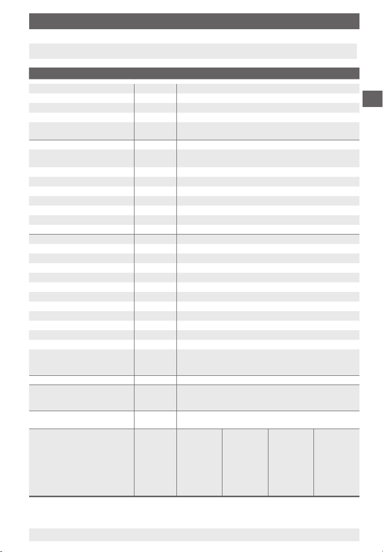
3. Technical data
3.1 Transmitter
Power supply U
Supply voltage effect
Permissible residual ripple
1)
B
DC V
% of FS/10 V
% ss
12 ≤ UB ≤ 30≤
≤ 0.1
≤ 10
Output signal, variant I 4 … 20 mA, 2-wire, passive, per NAMUR NE43
Permissible max. load R
Effect of load
A
% FS
- 12 V)/0.02 A with R
RA ≤ (U
B
however max. 600 Ω
≤ 0.1
in Ohm and UB in Volt
A
Output signal, variant II 4 … 20 mA, 2-wire - Ex≤, per ATEX Ex II 2G Ex ia IIC T4/T5/
Output signal, variant III 0 ... 20 mA, 3-wire
T6 or Ex I M2 Ex ia I
2)
Output signal, variant IV 0 ... 10 V *
Impendance on the voltage output
Load-carrying ability voltage output
Sample rate sensor
Electrical zero point
Zero point adustable range
Linearity
Output signal accuracy
Resolution
Update rate (measuring rate)
Input signal rotational angle
Expanded special span
Long-term stability of electronics
Temperature error, electronics
Warming-up time
Permissible ambient temperature
Permissible storage temperature
Permissible medium temperature
Ω
kΩ
ms
)
< °
% of span
% FS
% FS
1/s
)
< °
< °
)
% FS/a
% FS/10K
min.
°C
°C
°C
0.5
2 … 100
600, with 3-wire optionally faster
Zeroing through short-term jumper across ternimals 5 and 6
45
≤ 1.0 (limit point calibration)
0.2 (only electronic)
0.15 (10 bit resolution at 360°)
> 1
0 … 270
< 330 (Option)
< 0.3
< 0.3 (over the complete temperature range)
≤ 5
-40 … +60
-40 … +70
-40 … +100
Special function Option: non-proportional angular output signal, via auxili-
ary points and interpolation of the intermediate values (to
specify with the order)
CE-conformity Interference emission and immunity per EN 61 326-1
Wiring L-plug connector, 180 °C rotatable, max. 1.5 mm², wire
protector, Cable gland M20 x 1.5, External cable diameter
7-13 mm, incl. strain relief
Wiring protection IP65 to EN 60 529 / IEC 529;
Protected against reverse polarity and overvoltage
Connection details,
depending on variant
Terminal
No
1
2
3
4
5
6
Variant I
4 ... 20mA
GND
I+
reserved
reserved
Zeroing
Zeroing
Ex-Variant II
4 ... 20mA
GND
I+
reserved
reserved
Zeroing
Zeroing
Variant III
0 ... 20 mA
GND
UB+
I
out
reserved
Zeroing
Zeroing
Variant IV
0 ... 10V
GND
UB+
U
out
reserved
Zeroing
Zeroing
GB
1) Not model PGT23.063
2) Not model DPGT43HP.100 / DPGT43HP.160
11297264 05/2009 GB/D/F/E
WIKA Operating Instructions intelliGAUGE family 5
Page 6
3. Technical data
3.2 Transmitter with model PGT23.063
Power supply U
GB
Supply voltage effect % FS/10 V ≤ 0.1
Permissible residual ripple % ss ≤ 10
Output signal, variant I 4 … 20 mA, 2-wire
Permissible max. load R
Effect of load % FS ≤ 0.1
Linearity % of span ≤ 1.0 (limit point calibration)
Output signal accuracy % FS < 1.6 electronic
Input signal rotational angle < ° 0 … 270
Expanded special span < ° < 330 (option)
Long-term stability of electronics % FS/a < 0.5
Permissible ambient temperature °C -40 … +60
Permissible storage temperature °C -40 … +70
Permissible medium temperature °C -40 … +100
CE-conformity 2007/108/EC interference emission (Limit Class B) and
Wiring Free cable or as option miniature plug connector M8 x 1,
Wiring protection IP 54 per EN 60 529 / IEC 529, filled IP 65
Connection details see page 9
1) For technical reasons, up to the first scale marking, the measured value can lie outside of the class accuracy.
B
A
3.3 Model PGT23.063
Working pressure
- Steady 3/4 x full scale range
- Fluctuating 2/3 x full scale range
- Transient Full scale range
Temperature influence
IP protection class
- Housing IP 54 per EN 60 529 / IEC 60 529
- With liquid filling IP 65
Permissible temperatures
- Ambient filled/unfilled -40 ... +60 °C
- Medium Maximum +100 °C
Further technical data see data sheet PV 12.03
DC V 12 ≤ UB ≤ 30≤
- 12 V)/0.02 A with R
RA ≤ (U
B
max. 600 Ω
1)
)
)
immunity to EN 61 326-1
4-pin
in Ω and UB in Volt, but
A
1)
max. ± 0.4 % of full scale range/10 K (when the temperature of the
measuring system deviates from +20 °C reference temperature)
11297264 05/2009 GB/D/F/E
WIKA Operating Instructions intelliGAUGE family6
Page 7
3. Technical data
3.4 Model PGT23.100 / PGT23.160
Working pressure
- Steady Full scale range
- Fluctuating 0.9 x full scale range
- Transient 1.3 x full scale range
Temperature influence
IP protection class
- Housing IP 54 per EN 60 529 / IEC 60 529
- With liquid filling IP 65
Permissible temperatures
- Ambient filled/unfilled -40 ... +60 °C
- Medium maximum +100 °C
Further technical data see data sheet PV 12.04
3.5 Model PGT43.100 / PGT43.160
Working pressure
- Steady Full scale range
- Fluctuating 0.9 x full scale range
- Transient 5 x full scale range, however max. 40 bar
Temperature influence
IP protection class
- Housing IP 54 per EN 60 529 / IEC 60 529
- With liquid filling IP 65
Permissible temperatures
- Ambient filled/unfilled -20 ... +60 °C
- Medium maximum +100 °C
Further technical data see data sheet PV 14.03
max. ± 0.4 % of full scale range/10 K (when the temperature of the
measuring system deviates from +20 °C reference temperature)
max. ± 0.8 % of full scale range/10 K (when the temperature of the
measuring system deviates from +20 °C reference temperature)
GB
3.6 Model PGT43HP.100 / PGT43HP.160
Working pressure
- Steady Full scale range
- Fluctuating 0.9 x full scale range
- Overload capability 40, 100 and 400 bar
Temperature influence
IP protection class
- Housing IP 54 per EN 60 529 / IEC 60 529
- With liquid filling IP 65
Permissible temperatures
- Ambient filled/unfilled -20 ... +60 °C
- Medium maximum +100 °C
Further technical data see data sheet PV 14.07
11297264 05/2009 GB/D/F/E
max. ± 0.8 % of full scale range/10 K (when the temperature of the
measuring system deviates from +20 °C reference temperature)
WIKA Operating Instructions intelliGAUGE family 7
Page 8
3. Technical data
3.7 Model APGT43.100 / APGT43.160
Working pressure
GB
- Steady Full scale range
- Fluctuating 0.9 x full scale range
- Overload capability see data sheet PM 05.02
Temperature influence
IP protection class
- Housing IP 54 per EN 60 529 / IEC 60 529
- With liquid filling IP 65
Permissible temperatures
- Ambient filled/unfilled -20 ... +60 °C
- Medium maximum +100 °C
Further technical data see data sheet PV 15.02
3.8 Model PGT63HP.100 / PGT63HP.160
Working pressure
- Steady Full scale range
- Fluctuating 0.9 x full scale range
- Overload capability 50 x full scale range
Temperature influence
IP protection class
- Housing IP 54 per EN 60 529 / IEC 60 529
Permissible temperatures
- Ambient -20 ... +60 °C
- Medium maximum +100 °C
Further technical data see data sheet PV 16.06
max. ± 0.8 % of full scale range/10 K (when the temperature of the
measuring system deviates from +20 °C reference temperature)
max. ± 0.6 % of full scale range/10 K (when the temperature of the
measuring system deviates from +20 °C reference temperature)
3.9 Model DPGT43.100 / DPGT43.160
Working pressure
- Steady Full scale range
- Fluctuating 0.9 x full scale range
- Overload capability at least 10 x full scale value, max. 25 bar
Temperature influence
IP protection class
- Housing IP 54 per EN 60 529 / IEC 60 529
- With liquid filling IP 65
Permissible temperatures
- Ambient filled/unfilled -20 ... +60 °C
- Medium maximum +100 °C
Further technical data see data sheet PV 17.05
max. ± 0.5 % of full scale range/10 K (when the temperature of the
measuring system deviates from +20 °C reference temperature)
WIKA Operating Instructions intelliGAUGE family8
11297264 05/2009 GB/D/F/E
Page 9

3. Technical data
3.10 Model DPGT43HP.100 / DPGT43HP.160
Working pressure
- Steady Full scale range
- Fluctuating 0.9 x full scale range
- Overload capability 40, 100, 250 or 400 bar
Temperature influence
IP protection class
- Housing IP 54 per EN 60 529 / IEC 60 529
- With liquid filling IP 65
Permissible temperatures
- Ambient filled/unfilled -20 ... +60 °C
- Medium maximum +100 °C
Further technical data see data sheet PV 17.13
max. ± 0.5 % of full scale range/10 K (when the temperature of the
measuring system deviates from +20 °C reference temperature)
GB
11297264 05/2009 GB/D/F/E
WIKA Operating Instructions intelliGAUGE family 9
Page 10

4. Installation instructions
4. Installation instructions
The pressure gauge must be installed in a shock-free way and positioned in
GB
order to be clearly visible. We recommend connecting an interlocking device
between the pressure tapping point and the pressure gauge, enabling the
measuring device to be changed and to allow the zero point to be checked with
the plant still running.
Installation
Nominal position in accordance with EN 837-3 / 9.6.6 fig 7: 90° (⊥)
Bottom entry pressure connection
There must be a free space of at least 25 mm behind the housing to allow
the pressure to be safely and reliably vented through the rear wall in the
event of a fault!
To avoid supplementary heating, the instruments must not be exposed to
direct sunlight during operation!
With filled variants, open the vent valve (with pressure ranges ≤ 10 bar) on
the top of the housing before commissioning!
Permissible vibration load at the mounting point
The instruments should always be installed in locations free from vibration.
If necessary, it is possible to isolate the instrument from the mounting point
by installing a flexible connection line between the measuring point and the
pressure gauge and mounting the instrument on a suitable bracket.
If this is not possible, the following limit values must not be exceeded:
Unfilled devices: Frequency range < 150 Hz
Acceleration < 0.7 g (7 m/s²)
Liquid filled devices: Frequency range < 150 Hz
Acceleration < 4 g (40 m/s²)
Check the liquid filling at regular intervals.
The liquid level must not drop below 75 % of the instrument‘s diameter.
Test connector
Local safety codes such as those for pressure or steam vessels may specify
isolating devices to enable on-site testing of the pressure instrument.
10
WIKA Operating Instructions intelliGAUGE family
11297264 05/2009 GB/D/F/E
Page 11
4. Installation instructions
Mounting provisions
If the line for the pressure gauge is not rigid enough for vibration-free installation, fasten the instrument using appropriate fastening elements for wall and/or
pipe mounting, and, if necessary, by means of a capillary line.
Measuring system damping
If it is not possible to avoid vibration by means of appropriate mounting, use
pressure gauges with liquid filling.
Effects of temperature
The operating temperature of the pressure instrument, resulting from the effects
of radiated heat, must not exceed the temperature range the pressure instrument is intended for. Suitably-shaped tailpipes or syphons with water filling may
be used to separate the pressure transmitter and its isolating device from hot
pressure media.
The effective maximum surface temperature is not dependant
upon the device, but mainly on the temperature of the respective pressure medium! In the case of gaseous substances, the
temperature may increase due to compression warming. In
these cases it may be necessary to throttle the rate of change
of pressure or reduce the permissible temperature of the
pressure medium.
GB
Diaphragm seal/separating foil
In the case of aggressive, hot, highly viscous, contaminated or crystallising
pressure media, which must not be allowed to enter the measuring element,
diaphragm seals must be used as a separating barrier. A neutral transmission fluid, used to transmit the pressure to the measuring element, should be
selected with consideration to the measuring range, the temperature and its
compatibility with the pressure media.
Under no circumstances must the connection between the pressure gauge and
the diaphragm seal be loosened.
Protection of the measuring element against overload
If the pressure media is subject to rapid pressure changes, or pressure impulses may be expected, these must not act directly on the measuring element. The
effect of the pressure impulses must be damped, e.g. by installing an integrated
restrictor screw (reduction of the cross-section in the pressure channel) or by
connecting an adjustable throttle device in series.
11297264 05/2009 GB/D/F/E
WIKA Operating Instructions intelliGAUGE family 11
Page 12
4. Installation instructions / 5. Installation and commissioning
Pressure test connection
The pressure test connection, with a sufficiently large bore (≥ 6 mm diameter),
should be arranged, as far as possible, over a shut-off device, in a position
GB
where the accuracy of the reading will not be affected by the flow of the media
being measured.
The piping between the pressure test connection and the pressure instrument
should have an inner diameter large enough to avoid blockages or delays in
pressure transmission.
Also, it should not have any sharp bends. It is recom-
mended that it is mounted with a continuous incline of approx. 1:15.
Piping
The piping should be arranged and fitted so that it can withstand the stresses
caused by expansion, vibration and the influence of heat. When the media is
gaseous, a water drain point should be provided at the lowest point. For liquid
pressure media, an air bleed should be provided at the highest point.
5. Installation and commissioning
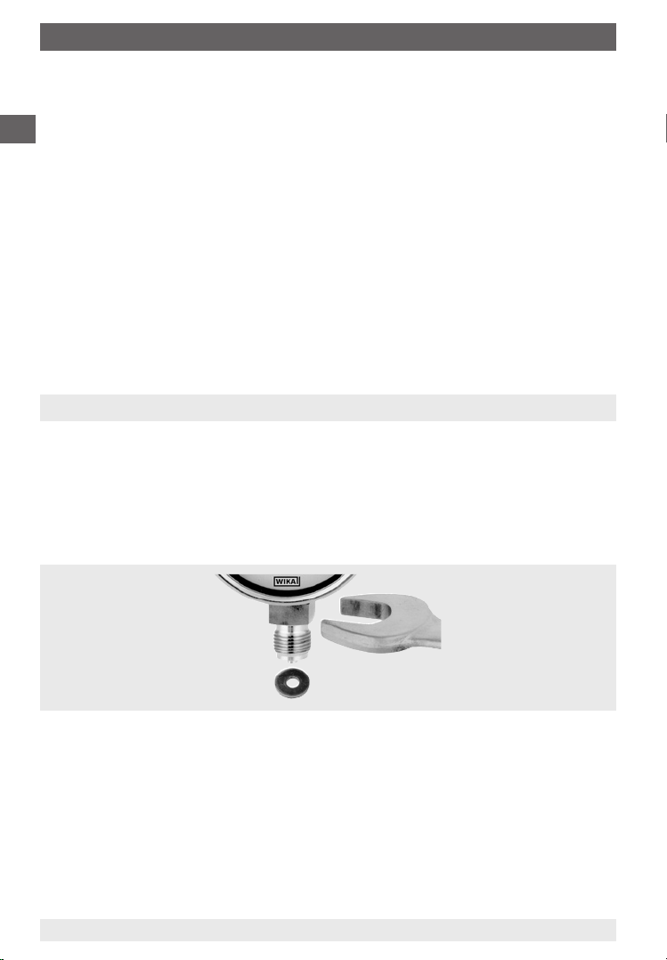
The correct sealing of pressure connections should be achieved by means of
suitable sealing rings, sealing washers or WIKA profile seals.
We recommend connection by means of a union nut or a LH-RH adjusting nut
in order to simplify correct orientation of the gauge. When mounting them or
removing them, the pressure gauges must not be tightened using the housing,
but only on the spanner flats on the stem!
Installation using
a spanner
If the pressure transmitter is positioned lower than the pressure test connection, the tailpipe should be thoroughly cleaned prior to fitting the transmitter.
For technical reasons, it is necessary to ventilate liquid-filled pressure gauges
after installation. See the relevant label on the pressure gauge.
WIKA Operating Instructions intelliGAUGE family12
11297264 05/2009 GB/D/F/E
Page 13
5. Installation and commissioning ... 6. Measuring arrangements
Once the pressure and electrical connections have been made, the transmitters
are ready for immediate use.
The A-VA-1 type or KFA6-STR-1.24.500 type feed units may be used to provide
the standard transmitter with DC voltage.
No attempt should be made to remove a pressurised instrument. If the transmitter cannot be otherwise isolated, the pressure system must be fully vented.
The clamping screws on the top and bottom flanges of diaphragm element
pressure gauges must not be unscrewed.
Any residual pressure medium contained in the pressure
element may be hazardous or toxic. This should be taken into
account when handling and storing pressure gauges which
have been removed.
Pressure connection
In accordance with the general technical regulations for pressure gauges (e.g.
EN 837-2 "Selection and installation recommendations for pressure gauges").
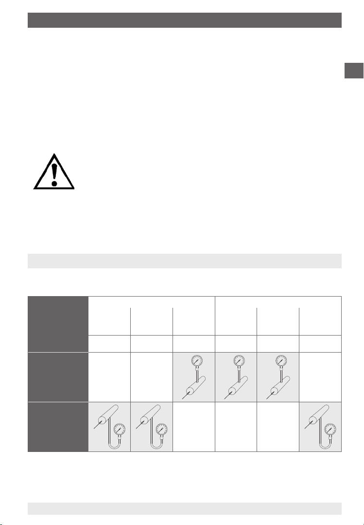
6. Measuring arrangements
Proven measuring arrangements for various types of media.
Liquid media Gaseous media
Contents of
tailpipe
Typically
Pressure
instrument
higher than
tapping point
Liquid Liquid with
vapour
Condensate Boiling liquid Liquefied gas Dry air Moist air,
Vapour
only
Gas only Wet gas Liquid gas
Flue gas
condensate
Steam
GB
Pressure
instrument
lower than
tapping point
11297264 05/2009 GB/D/F/E
WIKA Operating Instructions intelliGAUGE family 13
Page 14
7. Wiring details
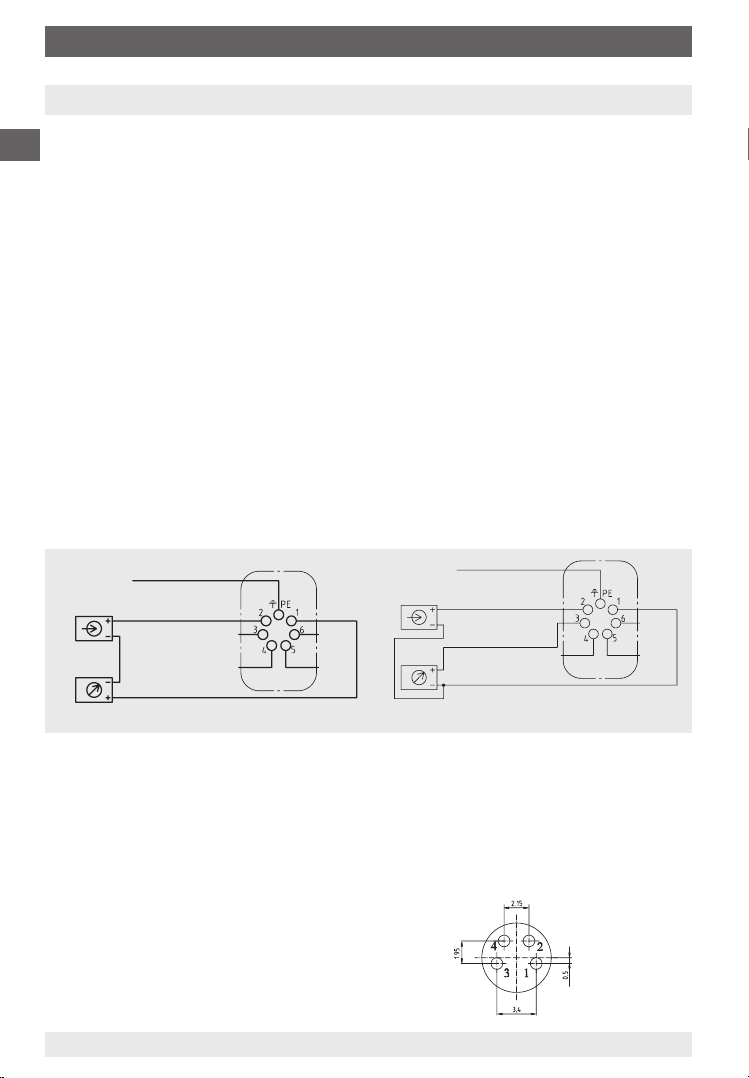
7. Wiring details
Electrical connection of this pressure transmitter is made via an L-plug connec-
GB
tor. Precise wiring diagrams can be found in the following drawings. In addition
to the wiring details, output signal and required power supply are given on the
rating plate.
Description of terminal designations used:
UB+ Plus terminal for supply voltage
0 V Minus terminal for supply voltage
Sig+ Plus terminal for output signal
Sig- Minus terminal for output signal
The instruments must be included within the plant’s equipotential bonding
Terminal assignment
Terminals 1 and 2 are the terminals for the signal output and for the power
supply. The terminal marked with PE (protective earth) is connected internally
to the housing. The connections 3 to 6 or 4 to 6 (for the 3-wire version), must
remain free and must not be used as connection points (also see Chapter 10
"Technical data").
2-wire design 3-wire design
i.e. 4 ... 20 mA i.e. 0 ... 20 mA / 0 ... 10 V
Power supply
Evaluation
(display/recorder)
ground, bonded/
connected to case
UB+/Sig+
+0V/Sig-
Connector housing
Terminals 3, 4, 5 and 6:
only for internal use
Power supply
Evaluation
(display/recorder)
ground, bonded/
connected to case
UB+/Sig+
I
out/Uout
+0V/Sig-
Terminals 4, 5 and 6:
only for internal use
An unstabilised DC voltage, with a residual ripple of max. 10 % peak-to-peak in
the range of the indicated supply voltage limits, is sufficient as a power supply.
Make sure that the supply voltage applied exceeds the maximum required
voltage by at least the value of the voltage drop across the external display
or evaluation devices; i.e. the transmitter can operate using a non-stabilised
supply voltage within the given limits, so long as the voltage available to the
transmitter does not fall below 12 V, or below 14 V for the Ex-version.
Connection details (only model PGT23.063)
Cable Plug connector Meaning
red Pin 1 U
black Pin 4 0 V/Sig -
+/Sig +
B
brown Pin 2 n.c.
- - - Pin 3 n.c
14
WIKA Operating Instructions intelliGAUGE family
11297264 05/2009 GB/D/F/E
Page 15
8. Instruments with ATEX approval
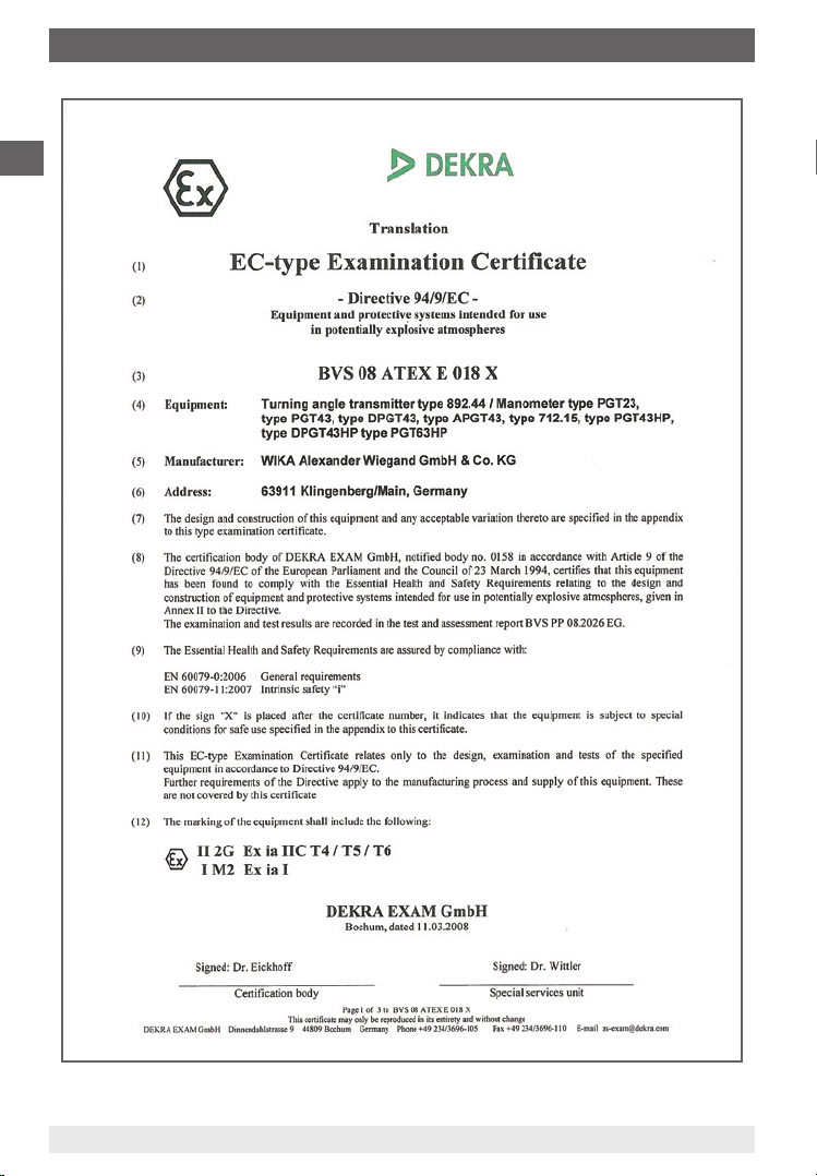
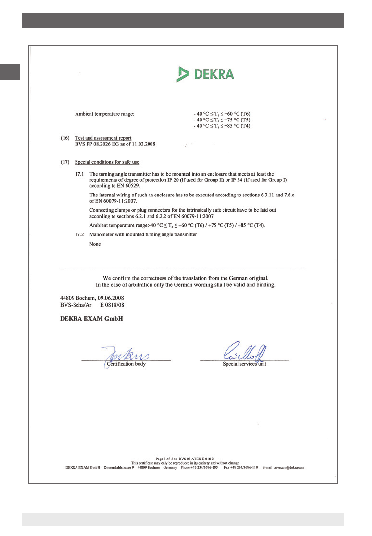
8. Instruments with ATEX approval
Read the operating conditions and the safety-related data
in the EC-type examination certificate (BVS 08 ATEX E018 X,
included in these operating instructions).
Key to symbols
ATEX
European directive for explosion protection (atmosphere=AT, explosive=EX)
The product corresponds to the requirements of the European Directive 94/9/
EC (ATEX) regarding explosion protection.
ATEX approval
Pressure gauges intended for the use in potentially explosive areas, see the
attached EC-type examination certificate BVS 08 ATEX E018 X
II 2G Ex ia IIc T4/T5/T6
I M2 Ex ia I
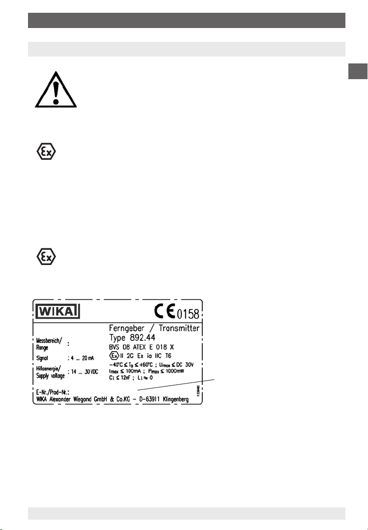
Product label (example)
Druckmessumformer
Pressure transmitter
PGT23.100
0 ... 10 bar
GB
≤ Coded date of manufacture
Month/year
(here April 2009)
11297264 05/2009 GB/D/F/E
WIKA Operating Instructions intelliGAUGE family 15
12345678 0409
Page 16
8. Instruments with ATEX approval
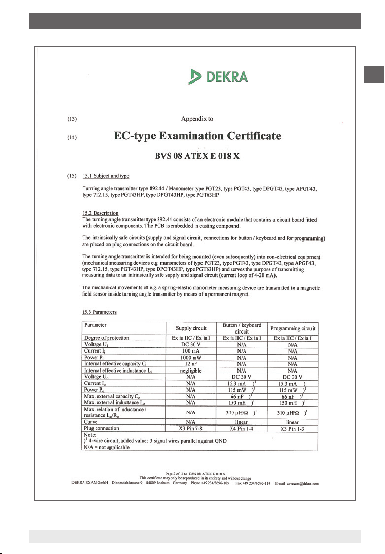
Conformity specifications
For instruments with ATEX approval the following conformity specifications,
which differ slightly from the specifications indicated in the data sheet, are
GB
applicable:
Power supply: 14 … 30 DC V
Short circuit rating: Imax ≤ 100 mA
Power: Umax ≤ 1000 mW
Internal capacitance: Ci ≤ 12 nF
Internal inductance: negligible
Safety instructions for installation
Observe the installation and safety instructions included in
the operating instructions
≤Install the instruments in accordance with the instructions of
the manufacturer and the applicable standards and regulations
≤Seal the cable entries using approved cable glands so that
they are leak-tight
≤Only use cable glands which possess an ATEX Ex e appro
val and have an ingress protection of at least IP 65.
Fix the connection cable securely
≤If intrinsically safe equipment is installed in hazardous areas,
it must only be operated as part of a certified intrinsically
safe circuit.
Transmitter supply isolators
When using ATEX instruments, an Ex transmitter supply isolator is an absolute
requirement.
We recommend Model KFD2-STC4-Ex1 with a power supply of 20 ... 35 DC V,
installation on standard rail, our order number 2341268
16
WIKA Operating Instructions intelliGAUGE family
-
11297264 05/2009 GB/D/F/E
Page 17

9. Service and maintenance
9. Service and maintenance
Always open isolating devices gently, never abruptly, since this may generate
sudden pressure surges that may damage the gauge. The maximum working
pressure for pressure gauges with transmitters is indicated by the limit marks
on the dial.
With fluctuating pressure loads, lower values apply in accordance with EN 837.
The pressure gauges with transmitters require no maintenance and feature a
long service life if handled and operated properly. As a result of the mechanical
loading, and depending on the service conditions, it may become necessary to
check and readjust the zero point of the transmitter.
Zero point test
Normally the zero point is checked and adjusted in an unpressurised state. The
zero point of differential pressure gauges with transmitters should be checked
and adjusted by opening the pressure compensating valve under static load.
Mechanical zero point (pointer)
If the pointer deviates from the zero point (in the unpres-
1)
Slotted
screw
surised condition), the zero point may be corrected by
means of the integrated adjustable pointer. To do this,
remove the bayonet ring, including the window and seal,
from the housing. The zero point is altered by turning the
adjusting screw on the adjustable pointer.
After correcting the zero point, fasten the bayonet ring
and the window with its seal and then close the pressure
compensating valve or open the stop valve.
GB
Electrical zero point (4 mA)
1)
If the mechanical zero point is changed by means of the adjustable pointer, the
electrical zero point must be reset to the mechanical zero point.
First depressurise the pressure gauge.
Loosen the complete cable hood on the right-hand side of the pressure gauge
by completely unscrewing the screw on the top of the cable hood cover
using an appropriate screwdriver (0.6 x 3.5 mm).
1) Not model PGT23.063
11297264 05/2009 GB/D/F/E
WIKA Operating Instructions intelliGAUGE family 17
Page 18
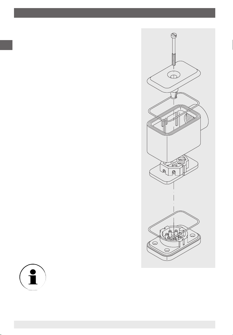
9. Service and maintenance
Extract the screw. Remove the cable hood
with the socket insert from the cable socket
base and thus separate the pressure gauge
GB
from the power supply.
Remove the cable hood cover from the
cable hood and push the socket insert
out downwards through the entire cable hood
.
Use a short stranded wire with bare points at
both ends (max. permissible resistance 30 Ω)
to bridge contacts 5 and 6 on the socket
insert.
Reassemble the plug in reverse order. Place
the plug, with the attached piece of stranded
wire, onto the pin insert , and thus reestablish the power supply.
Within a max. 30 seconds the new zero point
will be stored within the electronics. During
this period, the current in the loop will increase
to 9.5 mA.
The new zero point also remains stored in the
case of a power failure.
Loosen the plug again in the same sequence
as described above and remove the piece of
stranded wire. After reassembling the plug,
the electrical output signal will once more
correspond to the indication of the mechanical
pointer.
18
Ensure the seals are properly
and securely reinstalled to
maintain the protection class.
WIKA Operating Instructions intelliGAUGE family
Screw
Cable hood cover
Cable hood
Socket insert
Cable socket base
Seals
11297264 05/2009 GB/D/F/E
Page 19
10. Troubleshooting
10. Troubleshooting
Defect Possible reason Remedy
No signal output Failure of power supply or
wiring interrupted
Transmitter miswired Check wiring; if necessary
No pressure (only 3-wire)
Electronic defect through incorrect supply voltage or external
voltage
Steady signal, despite
pressure changes
Steady and excessively high signal,
despite pressure
changes
Full span reading too
low
Pressure entry blocked Check tailpipes and pressure
Supply voltage connected the
wrong way round
(I = approx. 4.5 mA)
Transmitter failure Return instrument to manufac-
Bridge between terminals 5
and 6 (I = approx. 9.5 mA) was
not removed
Electronic defect through incorrect supply voltage or external
voltage
Supply voltage too low Adjust supply voltage
Check power supply and
wiring; replace defective
components
rectify it
Check tailpipes
Return instrument to manufacturer for repair
entry bore, if necessary clean it
carefully
Check the clamping and, if
necessary, change terminals 1
and 2 around
turer for repair
Open the cable hood and
remove the bridge between the
terminals 5 and 6
Return instrument to manufacturer for repair
GB
Load impedance too high Consider permissible max. load
Zero point shifted Readjust the zero point (see
chapter 9)
Zero signal too low/
too high
11297264 05/2009 GB/D/F/E
WIKA Operating Instructions intelliGAUGE family 19
Zero point shifted Readjust the zero point (see
chapter 9)
Page 20

11. Storage / 12. Maintenance and servicing/cleaning
11. Storage
GB
Before installation, in order to prevent damage to the pressure instruments, the following points should be observed:
The pressure transmitter should be left in its original packing until installation.
After taking the transmitter out (e.g. for tests), reuse the original packaging
material.
The storage temperature should not be less than -40 °C or more than +70 °C.
Avoid the following influences:
Direct sunlight or vicinity to hot objects
Mechanical vibration
Soot, steam, dust, humidity and corrosive gasses
Potentially explosive environment, inflammable atmosphere
Before the system is stored, all traces of any medium residue
must be removed. This is particularly important if the medium
is a health hazard such as corrosive, toxic, carcinogenic,
radioactive, etc.
12. Maintenance and servicing/cleaning
The instruments require no maintenance or servicing and will give very long
service when handled and operated properly.
The indicator and switching function should be checked once or twice every 12
months. The instrument must be disconnected from the process before being
checked using pressure testing equipment.
The instruments should be cleaned with a damp cloth, moistened with soap
solution. Clean the instrument with a damp cloth. Particularly with regards to
ATEX model do not use a dry cloth for cleaning (electrostatic charging!)
Ensure that all parts are dry before the power is switched on again.
11297264 05/2009 GB/D/F/E
WIKA Operating Instructions intelliGAUGE family20
Page 21

13. Repairs / 14. Disposal
13. Repairs
Repairs should only be carried out by the manufacturer or appropriately trained
personnel.
For more technical data see the data sheet of the respective instrument:
Model PGT23.063 Data sheet PV 12.03
Model PGT23.100 / PGT23.160 Data sheet PV 12.04
Model PGT43.100 / PGT43.160 Data sheet PV 14.03
Model PGT43HP.100 / PGT43HP.160 Data sheet PV 14.07
Model APGT43.100 / APGT43.160 Data sheet PV 15.02
Model PGT63HP.100 / PGT63HP.160 Data sheet PV 16.06
Model DPGT43.100 / DPGT43.160 Data sheet PV 17.05
Model DPGT43HP.100 / DPGT43HP.160 Data sheet PV 17.13
14. Disposal
Dispose of instrument components and packaging materials in accordance
with the respective waste treatment and disposal regulations of the region or
country to which the instrument is supplied.
GB
11297264 05/2009 GB/D/F/E
WIKA Operating Instructions intelliGAUGE family 21
Page 22
15. EC-type Examination Certificate
GB
22
11297264 05/2009 GB/D/F/E
WIKA Operating Instructions intelliGAUGE family
Page 23
15. EC-type Examination Certificate
GB
11297264 05/2009 GB/D/F/E
WIKA Operating Instructions intelliGAUGE family 23
Page 24
15. EC-type Examination Certificate
GB
11297264 05/2009 GB/D/F/E
WIKA Operating Instructions intelliGAUGE family24
Page 25
Inhalt
Inhalt
1. Sicherheitshinweise 26
2. Funktionsprinzip 26
3. Technische Daten 27
4. Montagehinweise 32
5. Montage und Inbetriebnahme 34
6. Messanordnung 35
7. Elektrischer Anschluss 36
8. Geräte mit ATEX-Zulassung 37
9. Bedienung und Wartung 39
10. Maßnahmen bei Störungen 41
11. Lagerung 42
12. Wartung und Reinigung 42
13. Reparaturen 43
14. Entsorgung 43
15. EG-Baumusterprüfbescheinigung 44 - 46
D
Information
Dieses Zeichen gibt Ihnen Informationen, Hinweise oder
Tipps.
Warnung!
Dieses Symbol warnt Sie vor Handlungen, die Schäden an
Personen oder am Gerät verursachen können.
11297264 05/2009 GB/D/F/E
WIKA Betriebsanleitung intelliGAUGE-Familie 25
Page 26

1. Sicherheitshinweise / 2. Funktionsprinzip
1. Sicherheitshinweise
Beachten Sie unbedingt bei Montage, Inbetriebnahme und
Betrieb dieser Geräte die entsprechenden nationalen Sicher-
D
Bei Nichtbeachten der entsprechenden Vorschriften können schwere
Körperverletzungen und/oder Sachschäden auftreten.
Nur entsprechend qualifiziertes Personal darf an diesen Geräten arbei-
ten.
heitsvorschriften (z. B. EN 837-2 Auswahl- und Einbauempfehlungen für Druckmessgeräte).
2. Funktionsprinzip
Als Messelement für diesen Ferngeber werden die in der technischen Druckmesstechnik wegen ihrer Robustheit und einfachen Handhabung weit verbreiteten Rohr-, Platten-, Kapselfeder- und Wellrohrfedermessglieder verwendet.
Unter dem Einfluss eines Druckes verformen sich die Messglieder im
elastischen Bereich.
Diese Bewegung wird über ein mechanisches Messwerk (Zahnräder) in eine
Drehbewegung umgesetzt. Ein auf der Zeigerachse aufgesetzter Magnet dreht
sich proportional mit dem Instrumentenzeiger in direkter linearer Abhängigkeit
zum Prozessdruck. Die nachgeschaltete Elektronik erfasst die Drehbewegung
des Magneten im Bereich von 0 bis 270 Winkelgrade.
Ein magnetfeldabhängiger Sensor (Drehwinkelsensor, 10 bit Auflösung) greift
auf der elektrischen Seite diese Veränderung berührungslos ab und arbeitet
somit verschleißfrei.
Über einen Verstärker wird die Drehbewegung in ein elektrisches Ausgangssignal umgesetzt. Werkseitig ist die Elektronik auf das normierte Ausgangssignal
4 ... 20 mA passiv, eingestellt (0 ... 20 mA, 0 ... 10 V und 4 ... 20 mA ATEX-Version als Option verfügbar; nicht bei Typ PGT23.063). Die Spanne des elektrischen
Ausgangssignals entspricht der Messspanne auf dem Zifferblatt.
Durch die drei normierten elektrischen Ausgangssignale ist diese Gerätereihe in
allen Bereichen der Industrie einsetzbar.
Ein Druckmessgerät mit Ferngeber aus der intelliGAUGE-Reihe verbindet alle
Vorteile einer mechanischen Anzeige vor Ort mit der Forderung nach einer
elektrischen Signalübertragung für eine moderne Messwerterfassung in der
Industrie.
WIKA Betriebsanleitung intelliGAUGE-Familie26
11297264 05/2009 GB/D/F/E
Page 27
3. Technische Daten
3. Technische Daten
3.1 Transmitter
Hilfsenergie U
Einfluss der Hilfsenergie
Zulässige Restwelligkeit
1)
B
DC V
% v. EW/10 V
% ss
12 ≤ UB ≤ 30≤
≤ 0,1
≤ 10
Ausgangssignal, Variante I 4 … 20 mA, 2 Leiter, passiv, nach NAMUR NE43
Zulässige max. Bürde R
Bürdeneinfluss
A
% vom EW
- 12 V)/0,02 A mit R
RA ≤ (U
B
jedoch max. 600 Ω
≤ 0,1
in Ohm und UB in Volt
A
Ausgangssignal, Variante II 4 … 20 mA, 2-Leiter - Ex, nach ATEX Ex II 2G Ex ia IIC
Ausgangssignal, Variante III 0 ... 20 mA, 3-Leiter
T4/T5/T6 bzw. Ex I M2 Ex ia I
2)
Ausgangssignal, Variante IV 0 ... 10 V *
Impedanz am Spannungsausgang
Belastbarkeit Spannungsausgang
Abtastrate Sensor
Elektrischer Nullpunkt
Einstellbarkeit Nullpunkt
Kennlinienabweichung
Genauigkeit Ausgangssignal
Auflösung
Aktualisierungsrate (Messrate)
Eingangssignal Drehwinkel
Erweiterte Sonderspanne
Langzeitstabilität Elektronik
Temperaturfehler Elektronik
Aufwärmzeit
Zulässige Umgebungstemperatur
Zulässige Lagertemperatur
Zulässige Messstofftemperatur
Ω
kΩ
ms
< °
)
% d. Spanne
% vom EW
% vom EW
1/s
)
< °
< °
)
% vom EW/a
% v. EW/10K
min.
°C
°C
°C
0,5
2 … 100
600, bei 3-Leiter optional schneller
Nullung durch kurzzeitiges überbrücken der Klemmen 5 und 6
45
≤ 1,0 (Grenzpunkteinstellung)
0,2 (nur Elektronik)
0,15 (10 bit Auflösung bei 360°)
> 1
0 … 270
< 330 (Option)
< 0,3
< 0,3 (im gesamten Temperaturbereich)
≤ 5
-40 … +60
-40 … +70
-40 … +100
Sonderfunktion Option: beliebiges, nicht winkelproportionales Ausgangssi-
gnal über Stützstellen und Interpolation der Zwischenwerte
(bei Bestellung anzugeben)
CE-Kennzeichen Störemission und Störfestigkeit nach EN 61 326-1
Elektrischer Anschluss Über Winkelsteckverbinder, 180° verdrehbar, max. 1,5 mm²,
Drahtschutz, Kabelverschraubung M20 x 1,5,
Kabelaußendurchmesser 7-13 mm, inkl. Zugentlastung
Schutzart IP 65 nach EN 60 529 / IEC 529;
Verpolungs- und Überspannungsschutz
Belegung der Anschlussklemmen
je nach Variante des Ausgangssignals
Klemme
Art
1
2
3
4
5
6
Variante I
4 ... 20 mA
GND
I+
reserviert
reserviert
Nullung
Nullung
Ex-Variante II
4 ... 20 mA
GND
I+
reserviert
reserviert
Nullung
Nullung
Variante III
0 ... 20 mA
GND
UB+
I
out
reserviert
Nullung
Nullung
Variante IV
0 ... 10 V
GND
UB+
U
out
reserviert
Nullung
Nullung
D
1) Nicht bei Typ PGT23.063
2) Nicht bei Typ DPGT43HP.100 / DPGT43HP.160
11297264 05/2009 GB/D/F/E
WIKA Betriebsanleitung intelliGAUGE-Familie 27
Page 28

3. Technische Daten
3.2 Transmitter bei Typ PGT23.063
Hilfsenergie U
Einfluss der Hilfsenergie
Zulässige Restwelligkeit
Ausgangssignal, Variante I 4 … 20 mA, 2 Leiter
D
Zulässige max. Bürde R
Bürdeneinfluss
Kennlinienabweichung
Genauigkeit Ausgangssignal
Eingangssignal Drehwinkel
Erweiterte Sonderspanne
Langzeitstabilität Elektronik
Zulässige Umgebungstemperatur
Zulässige Lagertemperatur
Zulässige Messstofftemperatur
EMV-Richtlinie 2007/108/EG Störaussendung (Grenzwertklasse B) und
Elektrischer Anschluss Freies Kabel oder optional Miniatursteckverbinder M8 x 1,
Schutzart IP 54 nach EN 60 529 / IEC 529, gefüllt IP 65
Kabelbelegung siehe Seite 29
1) Aus technischen Gründen kann der Messwert bis zum ersten Teilstrich der Skala außerhalb der Klassengenauigkeit liegen
B
A
3.3 Typ PGT23.063
Druckbelastbarkeit
- Ruhebelastung 3/4 x Skalenendwert
- Wechselbelastung 2/3 x Skalenendwert
- Kurzzeitig Skalenendwert
Temperatureinfluss
Schutzart
- Umhüllendes Gehäuse IP 54 nach EN 60 529 / IEC 60 529
- Mit Flüssigkeitsfüllung IP 65
Zulässige Temperatur
- Umgebung Gefüllt/ungefüllt -40 ... +60 °C
- Messstoff Maximal +100 °C
Weitere technische Daten siehe Datenblatt PV 12.03
DC V
% v. EW/10 V
% ss
% vom EW
% d. Spanne
% vom EW
< °
)
)
< °
% vom EW/a
°C
°C
°C
12 ≤ UB ≤ 30≤
≤ 0,1
≤ 10
- 12 V)/0,02 A mit R
RA ≤ (U
B
max. 600 Ω
≤ 0,1
≤ 1,0 (Grenzpunkteinstellung)
< 1,6 Elektronik
0 … 270
< 330 (Option)
< 0,5
-40 … +60
-40 … +70
-40 … +100
Störfestigkeit nach EN 61 326-1
4-polig
1)
in Ohm und UB in Volt jedoch
A
1)
Bei Abweichung von der Referenztemperatur am Messsystem (+20 °C):
max. ± 0,4 %/10 K vom jeweiligen Skalenendwert
11297264 05/2009 GB/D/F/E
WIKA Betriebsanleitung intelliGAUGE-Familie28
Page 29

3. Technische Daten
3.4 Typ PGT23.100 / PGT23.160
Druckbelastbarkeit
- Ruhebelastung Skalenendwert
- Wechselbelastung 0,9 x Skalenendwert
- Kurzzeitig 1,3 x Skalenendwert
Temperatureinfluss
Schutzart
- Umhüllendes Gehäuse IP 54 nach EN 60 529 / IEC 60 529
- Mit Flüssigkeitsfüllung IP 65
Zulässige Temperatur
- Umgebung Gefüllt/ungefüllt -40 ... +60 °C
- Messstoff Maximal +100 °C
Weitere technische Daten siehe Datenblatt PV 12.04
3.5 Typ PGT43.100 / PGT43.160
Druckbelastbarkeit
- Ruhebelastung Skalenendwert
- Wechselbelastung 0,9 x Skalenendwert
- Kurzzeitig 5 x Skalenendwert, jedoch max. 40 bar
Temperatureinfluss
Schutzart
- Umhüllendes Gehäuse IP 54 nach EN 60 529 / IEC 60 529
- Mit Flüssigkeitsfüllung IP 65
Zulässige Temperatur
- Umgebung Gefüllt/ungefüllt -20 ... +60 °C
- Messstoff Maximal +100 °C
Weitere technische Daten siehe Datenblatt PV 14.03
Bei Abweichung von der Referenztemperatur am Messsystem (+20 °C):
max. ± 0,4 %/10 K vom jeweiligen Skalenendwert
Bei Abweichung von der Referenztemperatur am Messsystem (+20 °C):
max. ± 0,8 %/10 K vom jeweiligen Skalenendwert
D
3.6 Typ PGT43HP.100 / PGT43HP.160
Druckbelastbarkeit
- Ruhebelastung Skalenendwert
- Wechselbelastung 0,9 x Skalenendwert
- Überlastbarkeit 40, 100 und 400 bar
Temperatureinfluss
Schutzart
- Umhüllendes Gehäuse IP 54 nach EN 60 529 / IEC 60 529
- Mit Flüssigkeitsfüllung IP 65
Zulässige Temperatur
- Umgebung Gefüllt/ungefüllt -20 ... +60 °C
- Messstoff Maximal +100 °C
Weitere technische Daten siehe Datenblatt PV 14.07
11297264 05/2009 GB/D/F/E
Bei Abweichung von der Referenztemperatur am Messsystem (+20 °C):
max. ± 0,8 %/10 K vom jeweiligen Skalenendwert
WIKA Betriebsanleitung intelliGAUGE-Familie 29
Page 30

3. Technische Daten
3.7 Typ APGT43.100 / APGT43.160
Druckbelastbarkeit
- Ruhebelastung Skalenendwert
- Wechselbelastung 0,9 x Skalenendwert
- Überlastbarkeit siehe Datenblatt PM 05.02
D
Temperatureinfluss
Schutzart
- Umhüllendes Gehäuse IP 54 nach EN 60 529 / IEC 60 529
- Mit Flüssigkeitsfüllung IP 65
Zulässige Temperatur
- Umgebung Gefüllt/ungefüllt -20 ... +60 °C
- Messstoff Maximal +100 °C
Weitere technische Daten siehe Datenblatt PV 15.02
3.8 Typ PGT63HP.100 / PGT63HP.160
Druckbelastbarkeit
- Ruhebelastung Skalenendwert
- Wechselbelastung 0,9 x Skalenendwert
- Überlastbarkeit 50 x Skalenendwert
Temperatureinfluss
Schutzart
- Umhüllendes Gehäuse IP 54 nach EN 60 529 / IEC 60 529
Zulässige Temperatur
- Umgebung -20 ... +60 °C
- Messstoff Maximal +100 °C
Weitere technische Daten siehe Datenblatt PV 16.06
Bei Abweichung von der Referenztemperatur am Messsystem (+20 °C):
max. ± 0,8 %/10 K vom jeweiligen Skalenendwert
Bei Abweichung von der Referenztemperatur am Messsystem (+20 °C):
max. ± 0,6 %/10 K vom jeweiligen Skalenendwert
3.9 Typ DPGT43.100 / DPGT43.160
Druckbelastbarkeit
- Ruhebelastung Skalenendwert
- Wechselbelastung 0,9 x Skalenendwert
- Überlastbarkeit mindestens 10 x Skalenendwert, max. 25 bar
Temperatureinfluss
Schutzart
- Umhüllendes Gehäuse IP 54 nach EN 60 529 / IEC 60 529
- Mit Flüssigkeitsfüllung IP 65
Zulässige Temperatur
- Umgebung Gefüllt/ungefüllt -20 ... +60 °C
- Messstoff Maximal +100 °C
Weitere technische Daten siehe Datenblatt PV 17.05
Bei Abweichung von der Referenztemperatur am Messsystem (+20 °C):
max. ± 0,5 %/10 K vom jeweiligen Skalenendwert
WIKA Betriebsanleitung intelliGAUGE-Familie30
11297264 05/2009 GB/D/F/E
Page 31

3. Technische Daten
3.10 Typ DPGT43HP.100 / DPGT43HP.160
Druckbelastbarkeit
- Ruhebelastung Skalenendwert
- Wechselbelastung 0,9 x Skalenendwert
- Überlastbarkeit 40, 100, 250 oder 400 bar
Temperatureinfluss
Schutzart
- Umhüllendes Gehäuse IP 54 nach EN 60 529 / IEC 60 529
- Mit Flüssigkeitsfüllung IP 65
Zulässige Temperatur
- Umgebung Gefüllt/ungefüllt -20 ... +60 °C
- Messstoff Maximal +100 °C
Weitere technische Daten siehe Datenblatt PV 17.13
Bei Abweichung von der Referenztemperatur am Messsystem (+20 °C):
max. ± 0,5 %/10 K vom jeweiligen Skalenendwert
D
11297264 05/2009 GB/D/F/E
WIKA Betriebsanleitung intelliGAUGE-Familie 31
Page 32

4. Montagehinweise
4. Montagehinweise
Das Druckmessgerät muss erschütterungsfrei befestigt werden und soll gut
ablesbar angeordnet sein. Es empfiehlt sich, zwischen Druckentnahmestelle
und Druckmessgerät eine Absperrvorrichtung zwischenzuschalten, die einen
D
Austausch des Messgerätes und eine Nullpunktkontrolle bei laufender Anlage
ermöglicht.
Installation
Nennlage nach EN 837-3 / 9.6.6 Bild 7: 90° (
Druckanschluss unten
Damit im Fehlerfall die sichere Druckentlastung durch die Rückwand erfol-
gen kann, müssen hinter dem Gehäuse mindestens 25 mm frei bleiben!
Um zusätzliche Aufheizung zu vermeiden, dürfen die Geräte im Betrieb
keiner direkten Sonneneinstrahlung ausgesetzt werden!
Bei gefüllten Ausführungen muss vor Inbetriebnahme das Entlüftungsventil
(bei Druckbereichen ≤ 10 bar) an der Oberseite des Gehäuses geöffnet
werden!
Zulässige Schwingungsbelastung am Einbauort
Die Geräte sollten grundsätzlich nur an Stellen ohne Schwingungsbelastung
eingebaut werden
Gegebenenfalls kann z. B. durch eine flexible Verbindungsleitung von der
Messstelle zum Druckmessgerät und die Befestigung über eine Messgerätehalterung eine Entkopplung vom Einbauort erreicht werden.
Falls dies nicht möglich ist, dürfen folgende Grenzwerte nicht überschritten
werden:
⊥)
Ungefüllte Geräte: Frequenzbereich < 150 Hz
Beschleunigung < 0,7 g (7 m/s²)
Flüssigkeitsgefüllte Geräte: Frequenzbereich < 150 Hz
Beschleunigung < 4 g (40 m/s²)
Die Flüssigkeitsfüllung ist regelmäßig zu überprüfen.
Der Flüssigkeitsspiegel darf nicht unter 75 % des Gerätedurchmessers fallen.
Prüfanschluss
In bestimmten Anwendungsfällen (z. B. Dampfkessel) müssen die Absperrarmaturen einen Prüfanschluss besitzen, damit das Druckmessgerät ohne Ausbau
überprüft werden kann.
32
WIKA Betriebsanleitung intelliGAUGE-Familie
11297264 05/2009 GB/D/F/E
Page 33

4. Montagehinweise
Messgerätebefestigung
Ist die Leitung zum Druckmessgerät für eine erschütterungsfreie Anbringung
nicht stabil genug, so ist die Befestigung über entsprechende Befestigungselemente für Wand- und/oder Rohrmontage, gegebenenfalls über eine Kapillarleitung vorzunehmen.
Messsystemdämpfung
Können Erschütterungen nicht durch geeignete Installationen vermieden
werden, dann sollten Druckmessgeräte mit Flüssigkeitsfüllung eingesetzt
werden.
Temperaturbelastung
Die Anbringung des Druckmessgerätes ist so auszuführen, dass die zulässige
Betriebstemperatur, auch unter Berücksichtigung des Einflusses von Konvektion und Wärmestrahlung, weder unter noch überschritten wird. Dazu sind
Druckmessgerät und Absperrarmatur durch ausreichend lange Messleitungen
oder Wassersackrohre zu schützen.
Der Temperatureinfluss auf die Anzeige- bzw. Messgenauigkeit ist zu beachten.
Die tatsächliche maximale Oberflächentemperatur ist nicht
von diesen Geräten selbst abhängig, sondern hauptsächlich
von der jeweiligen Messstofftemperatur! Bei gasförmigen
Stoffen kann sich die Temperatur durch Kompressionswärme
erhöhen. In solchen Fällen muss ggf. die Druckänderungsgeschwindigkeit gedrosselt bzw. die zulässige Messstofftemperatur reduziert werden.
D
Druckmittler / Schutzvorlagen
Bei aggressiven, heißen, hochviskosen, verunreinigten oder kristallisierenden
Messstoffen, die nicht in das Messglied eindringen dürfen, sind Druckmittler als
Trennvorlagen vorzusehen. Zur Druckübertragung auf das Messglied dient eine
neutrale Mittlerflüssigkeit, die entsprechend dem Messbereich, der Temperatur
und der Verträglichkeit mit dem Messstoff auszuwählen ist.
Die Verbindung zwischen Druckmessgerät und Druckmittler darf auf keinen Fall
gelöst werden.
Schutz der Messglieder vor Überlastung
Unterliegt der Messstoff schnellen Druckänderungen oder ist mit Druckstößen
zu rechnen, dürfen diese nicht direkt auf das Messglied einwirken. Die Druckstöße müssen in ihrer Wirkung gedämpft werden, z. B. durch Einbau einer
Drosselstrecke (Verringerung des Querschnittes im Druckkanal) oder durch
Vorschaltung einer einstellbaren Drosselvorrichtung.
11297264 05/2009 GB/D/F/E
WIKA Betriebsanleitung intelliGAUGE-Familie 33
Page 34

4. Montagehinweise / 5. Montage und Inbetriebnahme
Druckentnahmestutzen
Der Druckentnahmestutzen soll mit einer genügend großen Bohrung (≥ 6 mm)
möglichst über ein Absperrorgan so angeordnet werden, dass die Druckentnahme nicht durch eine Strömung des Messstoffes verfälscht wird. Die Messleitung
zwischen Druckentnahmestutzen und Druckmessgerät soll zur Vermeidung von
D
Verstopfung und Verzögerungen bei der Druckübertragung einen genügend
großen Innendurchmesser besitzen. Sie soll auch ohne scharfe Krümmung sein.
Ihre Verlegung mit einer stetigen Neigung von ca. 1:15 ist zu empfehlen.
Messleitung
Die Messleitung ist so auszuführen und zu montieren, dass sie die auftretenden
Belastungen durch Dehnung, Schwingung und Wärmeeinwirkung aufnehmen
kann. Bei Gasen als Messstoff ist an der tiefsten Stelle eine Entwässerung, bei
flüssigen Messstoffen an der höchsten Stelle eine Entlüftung vorzusehen.
5. Montage und Inbetriebnahme
Zur Abdichtung der Anschlüsse sind Flachdichtungen, Dichtlinsen oder
WIKA-Profildichtungen einzusetzen. Um das Druckmessgerät in die Stellung
zu bringen, in der sich die örtliche Anzeige am besten ablesen lässt, ist ein
Anschluss mit Spannmuffe oder Überwurfmutter zu empfehlen. Beim Ein- und
Ausschrauben dürfen die Druckmessgeräte nicht am Gehäuse angezogen
werden, sondern nur an den Schlüsselflächen des Anschlussstutzens!
Montage mit
Gabelschlüssel
Ist das Druckmessgerät tiefer als der Druckentnahmestutzen angeordnet, muss
die Messleitung vor dem Anschließen gut durchgespült werden um Fremdkörper zu beseitigen. Nach der Montage sind die Druckmessgeräte, deren Gehäuse flüssigkeitsgefüllt sind, aus technischen Gründen zu belüften. Siehe dazu
den entsprechenden Aufkleber auf dem Druckmessgerät.
WIKA Betriebsanleitung intelliGAUGE-Familie34
11297264 05/2009 GB/D/F/E
Page 35

5. Montage und Inbetriebnahme / 6. Messanordnungen
Nach Herstellen der Druckverbindung und der elektrischen Anschlüsse sind die
Druckmessgeräte sofort betriebsbereit.
Zur Gleichspannungsversorgung des Ferngebers in Standardausführung
können die Speisegeräte Typ A-VA-1 oder Typ KFA6-STR-1.24.500 verwendet
werden.
Vor dem Ausbau des Druckmessgerätes ist das Messglied drucklos zu machen.
Gegebenenfalls muss die Messleitung entspannt werden. Bei Druckmessgeräten mit Plattenfedermessglied dürfen die Spannschrauben des Ober- und
Unterflansches nicht gelöst werden.
Messstoffreste in ausgebauten Druckmessgeräten können
zur Gefährdung von Menschen, Umwelt und Einrichtung
führen. Ausreichende Vorsichtsmaßnahmen sind zu ergreifen.
Druckanschluss
Entsprechend den allgemeinen technischen Regeln für Druckmessgeräte (z. B.
EN 837-2 „Auswahl- und Einbauempfehlungen für Druckmessgeräte“).
6. Messanordnungen
Bewährte Messanordnungen für verschiedene Messstoffarten.
D
flüssige Messstoffe gasförmige Messstoffe
Füllung der
Messleitung
Beispiele
Druckmessgerät
oberhalb des
Entnahmestutzens
Druckmessgerät
unterhalb des
Entnahmestutzens
11297264 05/2009 GB/D/F/E
WIKA Betriebsanleitung intelliGAUGE-Familie 35
flüssig zum Teil
Kondensat siedende
ausgasend
Flüssigkeiten
vollständig
verdampft
„Flüssiggase“ trockene Luft feuchte Luft,
gasförmig z. T. kon-
densiert
(feucht)
Rauchgase
vollständig
kondensiert
Wasserdampf
Page 36

7. Elektrischer Anschluss
7. Elektrischer Anschluss
Der elektrische Anschluss des Ferngebers wird über einen Winkelsteckverbinder hergestellt (nicht bei Typ PGT23.063). Die genauen Anschlussbelegungen
können den nachfolgenden Zeichnungen entnommen werden. Zusätzlich sind
D
Anschlussbelegung, Ausgangssignal und erforderliche Hilfsenergie auf dem
Typenschild vermerkt.
Bedeutung der verwendeten Klemmenbezeichnungen:
UB+ Plusklemme der Versorgungsspannung
0 V Minusklemme der Versorgungsspannung
Sig+ Plusklemme des Ausgangssignals
Sig- Minusklemme des Ausgangssignals
Die Geräte sind in den Potenzialausgleich der Anlage mit einzubeziehen.
Belegung der Anschlussklemmen
Die Klemmen 1 und 2 sind die Anschlussklemmen für den Signalausgang bzw. für die
Spannungsversorgung. Die mit PE (protective earth, Schutzleiter) gekennzeichnete
Klemme ist intern mit dem Gehäuse verbunden. Die Anschlüsse 3 bis 6, bzw. 4 bis 6
bei den 3 Leiter-Varianten sind frei zu lassen und dürfen auch nicht als Stützpunkte
verwendet werden (siehe auch Kapitel 10 „Technische Daten“).
2-Leiter-Ausführung 3-Leiter-Ausführung
z. B. 4 ... 20 mA z. B. 0 ... 20 mA / 0 ... 10 V
Hilfsenergie
Auswertung
(Anzeige)
Erde, verbunden
mit Gehäuse
UB+/Sig+
+0V/Sig-
Kabeldose
Klemmen 3, 4, 5 und 6:
nur für internen Gebrauch
Hilfsenergie
Auswertung
(Anzeige)
Erde, verbunden
mit Gehäuse
UB+/Sig+
I
out/Uout
+0V/Sig-
Klemmen 4, 5 und 6:
nur für internen Gebrauch
Als Hilfsenergie genügt eine unstabilisierte Gleichspannung mit einer Restwelligkeit
von max. 10 % ss im Bereich der angegebenen Versorgungsspannungsgrenzen.
Es ist darauf zu achten, dass die angelegte Versorgungsspannung um mindestens
den Betrag höher ist als die maximal erforderliche Spannung, die an den externen
Anzeige- und Auswertegeräten abfällt; d. h. die am Ferngeber anliegende Spannung
darf nicht unter 12 V und bei der Ex-Ausführung nicht unter 14 V fallen.
Kabelbelegung (nur bei Typ PGT23.063)
Kabel Steckverbinder Bedeutung
rot Pin 1 U
schwarz Pin 4 0 V/Sig -
+/Sig +
B
braun Pin 2 n.c.
- - - Pin 3 n.c
WIKA Betriebsanleitung intelliGAUGE-Familie36
11297264 05/2009 GB/D/F/E
Page 37

8. Geräte mit ATEX-Zulassung
8. Geräte mit ATEX-Zulassung
Lesen Sie unbedingt die Einsatzbedingungen und Sicherheitstechnischen Daten in der EG Baumusterprüfbescheinigung nach (BVS 08 ATEX E018 X, in dieser Betriebsanleitung enthalten).
Zeichenerklärung
ATEX
Europäische Explosionsschutz-Richtlinie (Atmosphäre=AT, Explosion=EX)
Das Produkt stimmt überein mit den Anforderungen der europäischen Richtlinie
94/9/EG (ATEX) zum Explosionsschutz.
Zulassung ATEX
Druckmessgeräte zur bestimmungsgemäßen Verwendung in explosionsgefährdeten Bereichen, siehe beiliegende EG-Baumusterprüfbescheinigung
BVS 08 ATEX E018 X
II 2G Ex ia IIc T4/T5/T6
I M2 Ex ia I
Typenschild (Beispiel)
Druckmessumformer
Pressure transmitter
PGT23.100
0 ... 10 bar
D
≤ Codiertes Herstellungsdatum
Monat/Jahr
(hier April 2009)
11297264 05/2009 GB/D/F/E
WIKA Betriebsanleitung intelliGAUGE-Familie 37
12345678 0409
Page 38

8. Geräte mit ATEX-Zulassung
Sicherheitstechnische Höchstwerte
Bei Geräten mit ATEX Zulassung gelten folgende, teilweise von dem Datenblatt
abweichende, sicherheitstechnische Höchstwerte:
Hilfsenergie: 14 … 30 DC V
D
Kurzschlussstrom: Imax ≤ 100 mA
Leistung: Umax ≤ 1000 mW
Innere Kapazität: Ci ≤ 12 nF
Innere Induktivität: vernachlässigbar
Sicherheitshinweise bei Installation
Die Installations- und Sicherheitshinweise der Betriebsanlei-
tung beachten
Geräte gemäß Herstellerangaben und den gültigen Normen
und Regeln installieren
Kabeleinführung mit entsprechend zugelassenen Kabelver-
schraubungen dicht verschließen
Nur Kabelverschraubungen mit ATEX-Ex e-Zulassung und
mindestens Schutzart IP 65 verwenden. Anschlusskabel
fest verlegen
Eigensichere Betriebsmittel dürfen in explosionsgefährdeten
Bereichen nur in eigensicher bescheinigten Stromkreisen
betrieben werden
Speisetrenner
Für die Anwendung von ATEX Geräten ist ein Ex-Speisetrenner zwingend erforderlich.
Wir empfehlen den Typ KFD2-STC4-Ex1 mit 20 ... 35 DC V Hilfsenergie,
Montage auf Normschiene, unsere Bestellnummer: 2341268
WIKA Betriebsanleitung intelliGAUGE-Familie38
11297264 05/2009 GB/D/F/E
Page 39

9. Bedienung und Wartung
9. Bedienung und Wartung
Absperreinrichtungen dürfen zur Vermeidung von Druckstößen nur langsam
geöffnet werden. Der Verwendungszweck für ruhende Belastung ist bei Druck-
messgeräten mit Ferngebern am Zifferblatt durch die Begrenzungsmarke ≤ auf
dem Zifferblatt gekennzeichnet.
Bei wechselnder Belastung gelten entsprechend EN 837 niedrigere Werte.
Die Druckmessgeräte mit Ferngeber sind wartungsfrei und zeichnen sich
bei sachgemäßer Behandlung und Bedienung durch eine hohe Lebensdauer
aus. Durch mechanische Belastung und je nach Einsatzbedingungen kann
es notwendig werden, dass der Nullpunkt des Ferngebers überprüft und ggf.
nachjustiert werden muss.
Nullpunktprüfung
Im Allgemeinen erfolgt die Überprüfung und Einstellung des Nullpunktes im
drucklosen Zustand. Bei Differenzdruckmessgeräten mit Ferngeber sollte die
Überprüfung und Einstellung des Nullpunktes durch Öffnen des Druckausgleichventils unter statischer Last erfolgen.
D
Mechanischer Nullpunkt (Zeiger)
Bei Abweichung des Zeigers von dem Nullpunkt (im
drucklosen Zustand), kann eine Nullpunktkorrektur über
1)
Schlitzschraube
den eingebauten Verstellzeiger erfolgen. Hierzu den
Bajonettring inklusive der Sichtscheibe und der Dichtung
vom Gehäuse entfernen. Die Nullpunkt-Verstellung wird
durch Verdrehen der Einstellschraube am Verstellzeiger
erreicht.
Nach erfolgter Nullpunktkorrektur den Bajonettring und
die Sichtscheibe mit der Dichtung wieder befestigen und
das Druckausgleichsventil schließen oder das Absperrventil öffnen.
Elektrischer Nullpunkt (4 mA)
1)
Wird der mechanische Nullpunkt über den Verstellzeiger verändert, sollte der
elektrische Nullpunkt wieder dem mechanischen angepasst werden.
Bringen Sie hierzu das Manometer zuerst in den drucklosen Zustand.
Lösen Sie die ganze Kabelhaube an der rechten Manometerseite in dem Sie mit
einem Schlitzschraubendreher (0,6 x 3,5 mm) die Schraube
an der Obersei-
te des Kabelhaubendeckels vollständig lösen. Nehmen Sie die Schraube
1) Nicht bei Typ PGT23.063
11297264 05/2009 GB/D/F/E
WIKA Betriebsanleitung intelliGAUGE-Familie 39
Page 40

9. Bedienung und Wartung
heraus. Ziehen Sie die Kabelhaube samt
Buchseneinsatz vom Kabeldosenunterteil
ab und trennen somit das Manometer von
der Spannungsversorgung.
D
Entfernen Sie den Kabelhaubendeckel
von der Kabelhaube und drücken Sie den
Buchseneinsatz ganz durch die Kabelhaube
nach unten heraus.
Überbrücken Sie die Kontakte 5 und 6 an dem
Buchseneinsatz mit einem kurzen, an beiden
Enden abisolierten Stück Litze (maximal zulässiger Widerstand 30 Ω).
Montieren Sie den Stecker wieder in
umgekehrter Reihenfolge. Stecken Sie den
Stecker mit montiertem Stück Litzendraht
auf den Stifteinsatz und stellen somit die
Versorgungsspannung wieder her.
Innerhalb von max. 30 Sekunden wird der neue
Nullpunkt in der Elektronik gespeichert. Während
dieser Zeit steigt der Strom in der Schleife auf
9,5 mA.
Der neue Nullpunkt bleibt auch bei
Spannungsausfall auf Dauer gespeichert.
Lösen Sie wieder den Stecker in der oben
beschriebenen Reihenfolge und entfernen das
Stück Litzendraht. Nach erneutem Montieren
des Steckers ist das elektrische Ausgangssignal wieder deckungsgleich mit der Anzeige
des mechanischen Zeigers.
Damit die Schutzart erhalten
bleibt, unbedingt die
Dichtungen wieder
montieren.
WIKA Betriebsanleitung intelliGAUGE-Familie40
Schraube
Kabelhaubendeckel
Kabelhaube
Buchseneinsatz
Kabeldosenunterteil
Dichtungen
11297264 05/2009 GB/D/F/E
Page 41

10. Maßnahmen bei Störungen
10. Maßnahmen bei Störungen
Störung mögliche Ursache Maßnahme
Kein Ausgangssignal keine Versorgungsspannung
oder Leitungsbruch
Ferngeber falsch angeschlossen
Kein
Eingangsdruck (nur 3 Leiter)
Elektronik defekt durch zu hohe
Versorgungsspannung oder
durch Fremdspannung
gleichbleibendes
Ausgangssignal bei
Druckänderung
zu hohes, bei Druckänderung gleichbleibendes Ausgangssignal
Signalspanne zu klein Versorgungsspannung zu
Nullpunktsignal zu
klein/zu groß
Eingangskanal verstopft Eingangskanal bzw. Drossel-
Versorgungsspannung verpolt
angeschlossen
(I = ca. 4,5 mA)
Ferngeber defekt Messgerät zur Instandsetzung
Brücke zwischen Klemmen 5
und 6 nicht entfernt
(I = ca. 9,5 mA)
Elektronik defekt durch zu hohe
Versorgungsspannung oder
durch Fremdspannung
niedrig
Bürde zu hoch max. zulässige Bürde beachten
Nullpunkt verstellt Nullpunkt neu setzen (siehe
Nullpunkt verstellt Nullpunkt neu setzen (siehe
Spannungsversorgung und
Leitungen überprüfen. Ggf.
defekte Teile austauschen
Anschlüsse überprüfen;
Anschlüsse ggf. korrigieren
Druckzuführung überprüfen
Messgerät zur Instandsetzung
an Hersteller zurück
schraube reinigen
Verklemmung prüfen und ggf.
Klemme 1 und 2 vertauschen
an Hersteller zurück
Kabelhaube öffnen und Brücke
zwischen Klemmen 5 und 6
entfernen
Messgerät zur Instandsetzung
an Hersteller zurück
Versorgungsspannung korrigieren
Kapitel 9)
Kapitel 9)
D
11297264 05/2009 GB/D/F/E
WIKA Betriebsanleitung intelliGAUGE-Familie 41
Page 42

11. Lagerung / 12. Wartung und Reinigung
11. Lagerung
Vor der Einlagerung des Gerätes müssen alle ggf. anhaftenden Mediumsreste entfernt werden. Dies ist besonders
D
Um Schäden zu vermeiden, sind für die Lagerung der Druckmessgeräte
folgende Punkte zu beachten:
Druckmessgeräte in der Originalverpackung belassen
Nach einer eventuellen Entnahme der Messgeräte für z.B. Prüfungen, sollte
das Gerät wieder in der Originalverpackung eingelagert werden
Lagertemperaturbereich -40 °C ... +70 °C
Vermeiden Sie folgende Einflüsse:
Direktes Sonnenlicht oder Nähe zu heißen Gegenständen
Mechanische Vibration, mechanischer Schock (hartes Aufstellen)
Ruß, Dampf, Staub, Feuchtigkeit und korrosive Gase
Explosionsgefährdete Umgebung, entzündliche Atmosphären
wichtig, wenn das Medium gesundheitsgefährdend ist, wie
z. B. ätzend, giftig, krebserregend, radioaktiv, usw.
12. Wartung und Reinigung
Die Geräte sind wartungsfrei und zeichnen sich bei sachgemäßer Behandlung
und Bedienung durch eine hohe Lebensdauer aus.
Eine Überprüfung der Anzeige und der Schaltfunktion sollte etwa 1 bis 2 mal
pro Jahr erfolgen. Dazu ist das Gerät vom Prozess zu trennen und mit einer
Druckprüfvorrichtung zu kontrollieren.
Reinigen der Geräte mit einem (in Seifenlauge) angefeuchteten Tuch.
Verwenden Sie insbesondere bei der ATEX-Ausführung KEIN trockenes Tuch
zum Abwischen des Gerätes (statische Aufladung!)
Vor Wiedereinschalten des Stromes ist sicherzustellen, dass alle Teile
abgetrocknet sind.
11297264 05/2009 GB/D/F/E
WIKA Betriebsanleitung intelliGAUGE-Familie42
Page 43

13. Reparaturen / 14. Entsorgung
13. Reparaturen
Reparaturen sind ausschließlich vom Hersteller oder entsprechend geschultem
Personal durchzuführen.
Weitere technische Daten entnehmen Sie bitte dem Datenblatt des jeweiligen
Gerätes:
Typ PGT23.063 Datenblatt PV 12.03
Typ PGT23.100 / PGT23.160 Datenblatt PV 12.04
Typ PGT43.100 / PGT43.160 Datenblatt PV 14.03
Typ PGT43HP.100 / PGT43HP.160 Datenblatt PV 14.07
Typ APGT43.100 / APGT43.160 Datenblatt PV 15.02
Typ PGT63HP.100 / PGT63HP.160 Datenblatt PV 16.06
Typ DPGT43.100 / DPGT43.160 Datenblatt PV 17.05
Typ DPGT43HP.100 / DPGT43HP.160 Datenblatt PV 17.13
14. Entsorgung
Entsorgen Sie Gerätekomponenten und Verpackungsmaterialien entsprechend
den einschlägigen landesspezifischen Abfallbehandlungs- und Entsorgungsvorschriften des Anliefergebietes.
D
11297264 05/2009 GB/D/F/E
WIKA Betriebsanleitung intelliGAUGE-Familie 43
Page 44

15. EG-Baumusterprüfbescheinigung
D
44
11297264 05/2009 GB/D/F/E
WIKA Betriebsanleitung intelliGAUGE-Familie
Page 45

15. EG-Baumusterprüfbescheinigung
D
11297264 05/2009 GB/D/F/E
WIKA Betriebsanleitung intelliGAUGE-Familie 45
Page 46

15. EG-Baumusterprüfbescheinigung
D
46
11297264 05/2009 GB/D/F/E
WIKA Betriebsanleitung intelliGAUGE-Familie
Page 47

Sommaire
Sommaire
1. Consignes de sécurité 48
2. Principe de fonctionnement 48
3. Données techniques 49
4. Instructions de montage 54
5. Installation et mise en service 56
6. Installation sur le point de mesure 57
7. Branchement électrique 58
8. Appareils avec l‘agrément ATEX 59
9. Commande et maintenance 61
10. Mesures à prendre en cas de pannes 63
11. Stockage 64
12. Entretien et nettoyage 64
13. Réparations 65
14. Mise au rebus 65
15.
Attenstation d'examen CE anglais
allemand
22 - 24
44 - 46
F
Informations
Ce signe vous donne des informations, des remarques ou
des conseils.
Avertissement !
Ce symbole vous avertit d'actions qui sont susceptibles
d'entraîner des dommages physiques ou matériels.
11297264 05/2009 GB/D/F/E
WIKA Mode d'emploi famille intelliGAUGE 47
Page 48

1. Consignes de sécurité / 2. Principe de fonctionnement
1. Consignes de sécurité
Respectez impérativement les directives de sécurité nationales correspondantes lors du montage, de la mise en service
et de l'exploitation de ces appareils (p. ex. EN 837-2 Choix et
recommandations relatives à l'installation de manomètres).
F
Le non-respect des instructions correspondantes est susceptible
d‘entraîner des risques de blessure et/ou des dégâts matériels.
Seul le personnel habilité et qualifié est autorisé à manipuler les instru-
ments.
2. Principe de fonctionnement
Ces transmetteurs utilisent comme éléments de mesure des systèmes à tube
manométrique, à membrane ou à capsule, qui constituent des systèmes de
mesure éprouvés, fiables et souples d’utilisation dans le domaine de la technique de mesure de pression.
Sous l'influence d'une pression, ces éléments de mesure se déforment dans
leur zone d'élasticité.
Ce mouvement est transformé en mouvement rotatif au moyen d'un dispositif
de mesure mécanique (roues dentées). Un aimant fixé sur l'axe de l'aiguille
tourne proportionnellement à la rotation de l'aiguille de l‘instrument en fonction
de la pression process. L'électronique en aval saisit le mouvement de rotation
de l'aimant sur une plage de 0 à 270 degrés d'angle.
Un capteur indépendant du champ magnétique (capteur d'angle de rotation,
résolution 10 bits) mesure du côté électrique cette modification sans le moindre
contact et travaille donc sans usure.
Au moyen d'un amplificateur, le mouvement de rotation est transformé en
signal de sortie électrique. En usine, l'électronique est réglée en standard sur
le signal de sortie 4 ... 20 mA (version 0 ... 20 mA, 0 ... 10 V et 4 ... 20 mA ATEX
disponible en option). La plage du signal de sortie électrique correspond à la
plage de mesure sur le cadran.
Ces appareils peuvent être utilisés dans tous les domaines de l'industrie grâce
à ces trois signaux de sortie électriques.
Un manomètre avec fonction transmetteur de la série intelliGAUGE allie tous les
avantages d'un affichage mécanique local et l'exigence de transmission d’un
signal électrique permettant l’acquisition des valeurs de mesure.
48
WIKA Mode d'emploi famille intelliGAUGE
11297264 05/2009 GB/D/F/E
Page 49

3. Données techniques
3. Données techniques
3.1 Transmetteur
Alimentation U
Influence de l'alimentation % de la pleine
Ondulation résiduelle admissible % ss ≤ 10
Signal de sortie, variante I 4 … 20 mA, 2 fils, passifs, selon NAMUR NE43
Charge max. admissible R
Influence de la charge % de la pleine
Signal de sortie, variante II
Signal de sortie, variante III 0 ... 20 mA, 3 fils
Signal de sortie, variante IV
Impédance sur la sortie de tension
Tolérance de charge sortie de tension k≤ 2 … 100
Fréquence de balayage du capteur ms 600, avec 3 fils en option plus rapide
Point zéro Mise à zéro en court-circuitant les bornes 5 et 6 pour une courte durée
Possibilité de réglage point zéro < ° 45
Linéarité % de l’échelle ≤ 1,0 (étalonnage points limites)
Précision du signal de sortie % de la pleine
Résolution % de la pleine
Taux d'actualisation (vitesse de lecture)
Angle de rotation signal d'entrée < ° 0 … 270
Echelle spéciale étendue < ° < 330 (option)
Stabilité à long terme de l‘électronique % de la pleine
Erreur de température de
l'électronique
Temps d'échauffement min. ≤ 5
Température ambiante admissible °C -40 … +60
Température de stockage admissible °C -40 … +70
Température du fluide de mesure
admissible
Fonction spéciale En option : signal de sortie arbitraire non proportionnel à l'angle via
Marquage CE Emission de perturbations et résistance aux perturbations selon
Branchement électrique Par connecteur coudé, tournable à 180°, max. 1,5 mm²,
Indice de protection IP65 selon EN 60 529 / IEC 529 ; Irréversibilité et protection contre les
Affectation des bornes de raccordement en fonction de la variante du
signal de sortie
1) Sauf type PGT23.063
2)
Sauf type DPGT43HP.100 / DPGT43HP.160
11297264 05/2009 GB/D/F/E
B
WIKA Mode d'emploi famille intelliGAUGE 49
1)
C.C. V 12 ≤ UB ≤ 30≤
échelle/10K
A
échelle
Ω
kΩ
)
échelle
échelle
1/s > 1
)
)
échelle/a
% de la pleine
échelle/10K
°C -40 … +100
Borne
Type
1
2
3
4
5
6
≤ 0,1
RA ≤ (UB - 12 V)/0,02 A avec RA en ohm et UB en volt cependant 600 Ω
au maximum
≤ 0,1
4 … 20 mA, 2 fils - Ex, selon
Ex I M2 Ex ia I
0 ... 10 V *
0,5
0,2 (uniquement le système électronique)
0,15 (10 bit résolution à 360°)
< 0,3
< 0,3 (sur toute la plage de température)
points de reprise et interpolation des valeurs intermédiaires (à indiquer
lors de la commande)
EN 61 326-1
Protection de câble, passe-câble à vis M20 x 1,5,
Diamètre extérieur du câble 7-13 mm, délestage de traction inclus
surtensions
Variante I
4 ... 20 mA
GND
I+
Réservé
Réservé
Mise à zéro
Mise à zéro
ATEX Ex II 2G Ex ia IIC T4/T5/T6 ou
2)
Variante Ex II
4 ... 20 mA
GND
I+
Réservé
Réservé
Mise à zéro
Mise à zéro
Variante III
0 ... 20 mA
GND
UB+
Iout
Réservé
Mise à zéro
Mise à zéro
Variante IV
0 ... 10 V
GND
UB+
Uout
Réservé
Mise à zéro
Mise à zéro
F
Page 50

3. Données techniques
3.2 Transmetteur pour type PGT23.063
A
DC V
% de la pleine
échelle
% ss
% de E.M.
% de l’échelle
% de la pleine
échelle
< °
)
)
< °
% de la pleine
échelle/a
°C
°C
°C
12 ≤ UB ≤ 30≤
≤ 0,1
≤ 10
- 12 V)/0,02 A avec R
RA ≤ (U
B
cependant 600 Ω au maximum
≤ 0,1
≤ 1,0 (Réglage sur point limites)
< 1,6 électronique
0 … 270
< 330 (option)
< 0,5
-40 … +60
-40 … +70
-40 … +100
résistance aux perturbations selon EN 61 326-1
1)
en Ohm et UB en Volt
A
1)
Alimentation U
Influence de l'alimentation
Ondulation résiduelle admissible
Signal de sortie, variante I 4 … 20 mA, 2-fils
Charge max. admissible R
F
Influence de la charge
Linéarité
Précision du signal de sortie
Angle de rotation signal d'entrée
Echelle spéciale étendue
Stabilité à long terme de
l‘électronique
Température ambiante admis-
sible
Température de stockage
admissible
Température du fluide de
mesure admissible
Marquage CE 2007/108/EG Emission de perturbations (classe B) et
Branchement électrique Câble libre ou connecteur miniature optionnel M8 x 1, 4-pin
Indice de protection IP 54 (EN 60 529 / IEC 529), rempli IP 65
Raccordement électrique voir page 49
1) Pour des raisons techniques, la valeur mesurée jusqu' à la première graduation de l'échelle peut être hors de la précision de classe.
B
3.3 Type PGT23.063
Domaines d‘utilisation
- Charge statique 3/4 x fin d'échelle
- Charge dynamique 2/3 x fin d'échelle
- Temporaire Fin d'échelle
Influence de la température
Indice de protection
- Boîtier enveloppant IP 54 (EN 60 529 / IEC 60 529)
- Avec remplissage de liquide IP 65
Températures admissibles
- Environnement Rempli/pas rempli -40 ... +60 °C
- Fluide de mesure +100 °C au maximum
Autres caractéristiques techniques : voir Fiche technique PV 12.03
50
En cas de divergence de la température de référence sur le système
de mesure (+20 °C) : max. ± 0,4 %/10 K de la valeur d‘échelle finale
respective
WIKA Mode d'emploi famille intelliGAUGE
11297264 05/2009 GB/D/F/E
Page 51

3. Données techniques
3.4 Type PGT23.100 / PGT23.160
Domaines d‘utilisation
- Charge statique Fin d'échelle
- Charge dynamique 0,9 x fin d'échelle
- Temporaire 1,3 x fin d'échelle
Influence de la température
Indice de protection
- Boîtier enveloppant IP 54 (EN 60 529 / IEC 60 529)
- Avec remplissage de liquide IP 65
Températures admissibles
- Environnement Rempli/pas rempli -40 ... +60 °C
- Fluide de mesure +100 °C au maximum
Autres caractéristiques techniques : voir Fiche technique PV 12.04
3.5 Type PGT43.100 / PGT43.160
Domaines d‘utilisation
- Charge statique Fin d'échelle
- Charge dynamique 0,9 x fin d'échelle
- Temporaire 5 x fin d‘échelle, cependant 40 bars au maximum
Influence de la température
Indice de protection
- Boîtier enveloppant IP 54 (EN 60 529 / IEC 60 529)
- Avec remplissage de liquide IP 65
Températures admissibles
- Environnement Rempli/pas rempli -20 ... +60 °C
- Fluide de mesure +100 °C au maximum
Autres caractéristiques techniques : voir Fiche technique PV 14.03
En cas de divergence de la température de référence sur le système
de mesure (+20 °C) : max. ± 0,4 %/10 K de la valeur d‘échelle finale
respective
En cas de divergence de la température de référence sur le système
de mesure (+20 °C) : max. ± 0,8 %/10 K de la valeur d‘échelle finale
respective
F
3.6 Type PGT43HP.100 / PGT43HP.160
Domaines d‘utilisation
- Charge statique Fin d'échelle
- Charge dynamique 0,9 x fin d'échelle
- Capacité de surcharge 40, 100 et 400 bar
Influence de la température
Indice de protection
- Boîtier enveloppant IP 54 (EN 60 529 / IEC 60 529)
- Avec remplissage de liquide IP 65
Températures admissibles
- Environnement Rempli/pas rempli -20 ... +60 °C
- Fluide de mesure +100 °C au maximum
11297264 05/2009 GB/D/F/E
Autres caractéristiques techniques : voir Fiche technique PV 14.07
En cas de divergence de la température de référence sur le système
de mesure (+20 °C) : max. ± 0,8 %/10 K de la valeur d‘échelle finale
respective
WIKA Mode d'emploi famille intelliGAUGE 51
Page 52

3. Données techniques
3.7 Type APGT43.100 / APGT43.160
Domaines d‘utilisation
- Charge statique Fin d'échelle
- Charge dynamique 0,9 x fin d'échelle
- Capacité de surcharge voir Fiche technique PM 05.02
Influence de la température
F
Indice de protection
- Boîtier enveloppant IP 54 (EN 60 529 / IEC 60 529)
- Avec remplissage de liquide IP 65
Températures admissibles
- Environnement Rempli/pas rempli -20 ... +60 °C
- Fluide de mesure +100 °C au maximum
Autres caractéristiques techniques : voir Fiche technique PV 15.02
3.8 Type PGT63HP.100 / PGT63HP.160
Domaines d‘utilisation
- Charge statique Fin d'échelle
- Charge dynamique 0,9 x fin d'échelle
- Capacité de surcharge 50 x fin d'échelle
Influence de la température
Indice de protection
- Boîtier enveloppant IP 54 (EN 60 529 / IEC 60 529
Températures admissibles
- Environnement -20 ... +60 °C
- Fluide de mesure +100 °C au maximum
Autres caractéristiques techniques : voir Fiche technique PV 16.06
En cas de divergence de la température de référence sur le système
de mesure (+20 °C) : max. ± 0,8 %/10 K de la valeur d‘échelle finale
respective
En cas de divergence de la température de référence sur le système
de mesure (+20 °C) : max. ± 0,6 %/10 K de la valeur d‘échelle finale
respective
3.9 Type DPGT43.100 / DPGT43.160
Domaines d‘utilisation
- Charge statique Fin d'échelle
- Charge dynamique 0,9 x fin d'échelle
- Capacité de surcharge au moins 10 x fin d‘échelle, max. 25 bar
Influence de la température
Indice de protection
- Boîtier enveloppant IP 54 (EN 60 529 / IEC 60 529)
- Avec remplissage de liquide IP 65
Températures admissibles
- Environnement Rempli/pas rempli -20 ... +60 °C
- Fluide de mesure +100 °C au maximum
Autres caractéristiques techniques : voir Fiche technique PV 17.05
En cas de divergence de la température de référence sur le système
de mesure (+20 °C) : max. ± 0,5 %/10 K de la valeur d‘échelle finale
respective
WIKA Mode d'emploi famille intelliGAUGE52
11297264 05/2009 GB/D/F/E
Page 53

3. Données techniques
3.10 Type DPGT43HP.100 / DPGT43HP.160
Domaines d‘utilisation
- Charge statique Fin d'échelle
- Charge dynamique 0,9 x fin d'échelle
- Capacité de surcharge 40, 100, 250 ou 400 bars
Influence de la température
Indice de protection
- Boîtier enveloppant IP 54 (EN 60 529 / IEC 60 529)
- Avec remplissage de liquide IP 65
Températures admissibles
- Environnement Rempli/pas rempli -20 ... +60 °C
- Fluide de mesure +100 °C au maximum
Autres caractéristiques techniques : voir Fiche technique PV 17.13
En cas de divergence de la température de référence sur le système
de mesure (+20 °C) : max. ± 0,5 %/10 K de la valeur d‘échelle finale
respective
F
11297264 05/2009 GB/D/F/E
WIKA Mode d'emploi famille intelliGAUGE 53
Page 54

4. Instructions de montage
4. Instructions de montage
Le manomètre doit être fixé de manière à ne pas devoir subir de vibrations et
doit être placé de manière à permettre une lecture aisée. Il est recommandé de
monter un dispositif d’isolement entre la prise de pression et le manomètre, ce
qui permet de remplacer le manomètre ou d'en contrôler le point zéro alors que
l'installation est en service.
F
Installation
Position nominale selon EN 837-3 / 9.6.6 figure 7 : 90° (
Raccord de pression vertical
Il doit y avoir un espace libre d’au moins 25 mm à l'arrière de l'appareil
pour permettre l'éjection de la paroi arrière du boîtier en cas de défaillance
éventuelle de l'appareil suite à une surpression interne.
Afin d'éviter un échauffement additionnel, les appareils ne doivent pas être
exposés directement aux rayons solaires pendant le fonctionnement !
Avec les appareils à boîtier rempli, la mise à l'atmosphère doit être ouverte
avant la mise en service (pour les étendures de mesure ≤ 10 bars).
Contrainte de vibration admissible au point de mesure
Par principe, les appareils doivent être installés à des emplacements qui ne
sont pas soumis à des vibrations.
Le cas échéant, il est possible d'isoler l'appareil du point de mesure en utili-
sant par exemple un flexible entre le point de mesure et le manomètre et en
installant celui-ci à l'aide d‘un support pour appareil de mesure.
Dans le cas où cela n'est pas possible, les seuils suivants ne doivent pas
être dépassés :
⊥)
Appareils non remplis : plage de fréquence < 150 Hz
Accélération < 0,7 g (7 m/s²)
Appareils remplis : plage de fréquence < 150 Hz
Accélération < 4 g (40 m/s²)
Le niveau de liquide doit être contrôlé régulièrement.
Le niveau de remplissage du liquide ne doit pas descendre au-dessous de
75 % du diamètre du boîtier.
Prise de contrôle
Les spécifications locales de sécurité telles par exemple celles liées aux
chaudières vapeur peuvent rendre nécessaire des dispositifs d’isolement
permettant le test sur site de l'appareil.
54
WIKA Mode d'emploi famille intelliGAUGE
11297264 05/2009 GB/D/F/E
Page 55

4. Instructions de montage
Fixation des appareils de mesure
Si le raccordement au manomètre n'est pas assez robuste pour réaliser une
fixation exempte de vibrations, la fixation doit être réalisée au moyen d'éléments de fixation pour montage mural et/ou sur tube, le cas échéant par l'intermédiaire d'un capillaire.
Amortissement du système de mesure
Si des vibrations ne peuvent pas être évitées au moyen d'installations appropriées, il est recommandé d‘utiliser des manomètres remplis de liquide.
Contraintes thermiques
La position du transmetteur de pression est à choisir en fonction de la température de service qui ne doit pas être dépassée, en tenant compte également
de l'influence de la conduction et du rayonnement thermique. Pour ce faire on
utilisera des tuyaux-raccord suffisamments longs ou un syphon placé avant le
robinet d’isolement et le transmetteur de pression (prendre en considération
l'influence de la température sur la précision de la mesure).
La température maximale réelle de surface n‘est pas fonction
de l'appareil lui-même, mais principalement de la température
du fluide de mesure utilisé ! Dans le cas de fluides gazeux, la
température peut augmenter en raison de la chaleur consécutive à la compression. Dans un tel cas, il conviendra de
chercher à diminuer la vitesse d'évolution de la pression ou la
température admissible du fluide
Séparateurs / feuille de séparation
En cas de fluide agressif, chaud, fortement visqueux, souillé ou cristallisant
qui ne doive pas pénétrer dans l'organe de mesure, on utilisera un séparateur qui fera office de barrière de protection pour l'instrument. Un liquide de
transmission qui servira à transmettre la pression à l'organe de mesure devra
être sélectionné en fonction de la plage de mesure, de la température et de la
compatibilité avec le fluide de mesure.
L'assemblage du manomètre sur le séparateur ne devra en aucun cas être
démonté
F
Protection de l'éléments de mesure contre les surpressions
Si le fluide de mesure est soumis à de brusques montées en pression ou s'il
faut s‘attendre à des coups de bélier, ceux-ci ne doivent pas agir directement
sur l‘organe de mesure. Les effets des coups de bélier doivent être amortis,
p. ex. par la pose d'une vis frein (amoindrissement de la section dans le canal
de pression) ou par l'installation en amont d‘un dispositif d'amortissement de la
pression réglable.
11297264 05/2009 GB/D/F/E
WIKA Mode d'emploi famille intelliGAUGE 55
Page 56

4. Instructions de montage / 5. Installation et mise en service
Raccord de la prise de pression
Le raccord de la prise de pression doit être pourvu d'un orifice suffisamment
grand (6 mm), si possible posséder un robinet d'isolement et être installé de
façon à ce que le débit du fluide ne perturbe pas la mesure. La tuyauterie entre
le raccord de mesure et le transmetteur de pression doit avoir un diamètre suffisant afin d'en éviter son bouchage ou de provoquer des retards dans la transmission de la pression. On évitera également des courbures trop importantes. Il
F
est recommandé d'installer la tuyauterie avec un rapport d'inclinaison de 1:15.
Tuyauterie
La tuyauterie est à concevoir et à installer de telle façon qu'elle supporte les
contraintes dues á des dilatations, vibrations et influences thermiques. Pour la
mesure de gaz, il faut prévoir une purge de condensat au point le plus bas de
l'installation, et pour la mesure de liquides il faut une purge d'air au point le plus
èlevé.
5. Installation et mise en service
Pour l'étanchéité des raccords, il faut utiliser des joints plats, des lentilles
d'étanchéité ou des joints profilés WIKA. Pour installer le manomètre dans
la position permettant la lecture la plus aisée de l'indication locale, il est
recommandé de réaliser le raccordement au moyen d'un écrou tournant ou
d'un écrou-chapeau. Lors du montage ou du démontage, les manomètres ne
doivent pas être serrés au niveau du boîtier, mais uniquement sur le surplat audessus du filetage du manomètre !
Montage avec
clé à fourche
En cas d'installation du transmetteur de pression au-dessous du point de
mesure, il faut nettoyer soigneusement la tuyauterie afin d'éviter que des
particules pénètrent à l'intérieur de l'appareil. Pour des raisons techniques, les
manomètres dont le boîtier est rempli de liquide doivent être mis à l'atmosphère
après installation (voir à ce sujet l'étiquette adhésive située sur le manomètre).
56
WIKA Mode d'emploi famille intelliGAUGE
11297264 05/2009 GB/D/F/E
Page 57

5. Installation ... 6. Installation sur le point de mesure
Après réalisation du raccord de pression et des branchements électriques, les
transducteurs sont prêts à fonctionner.
Les alimentations type A-VA-1 ou type KFA6-STR-1.24.500 peuvent être utilisés
pour l'alimentation en tension continue du transmetteur.
Le transmetteur de pression doit être démonté uniquement lorsqu'il est hors
pression. Si nécessaire vider la tuyauterie. Pour les manomètres à membrane,
les vis de serrage de la flasque supérieure ou inférieure ne doivent pas être
dévissées.
Les résidus de fluide se trouvant à l'intérieur des transmetteurs de pression démontés peuvent présenter des dangers
pour les personnes, l'environnement et les installations. Il
faut prendre toutes les précautions nécessaires pour en
assurer la sécurité.
Raccord de pression
Conformément aux règles techniques générales pour les manomètres (par
ex. EN 837-2 « Recommandations relatives au choix et à l'installation des
manomètres »).
6. Installation sur le point de mesure
Types d’installations éprouvés selon différents fluides.
F
fluides liquides fluides gazeux
Remplissage
de la conduite
de mesure
Exemples
liquides en partie
condensat liquides en
gazeux
ébullition
complètement
évaporés
« gaz liquides »
fluide
gazeux
air sec air humide,
en partie
condensés
(humides)
gaz de
combustion
entièrement
condensé
vapeur d‘eau
Manomètre
au-dessus
du point de
mesure
Manomètre
au-dessous
du point de
mesure
11297264 05/2009 GB/D/F/E
WIKA Mode d'emploi famille intelliGAUGE 57
Page 58

7. Branchement électrique
7. Branchement électrique
Le raccordement électrique des transmetteurs de pression s'effectue à l'aide
d'un connecteur coudé. La disposition exacte des connections est illustrée
sur les dessins présentés ci-après. En outre, la disposition des connections, le
signal de sortie et l'alimentation auxiliaire nécessaires sont notés sur la plaque
signalétique de l'appareil.
F
Signification des différents symboles de borne utilisés:
UB+ Borne positive de la tension d'alimentation
0 V Borne négative de la tension d'alimentation
Sig+ Borne positive du signal de sortie
Sig- Borne négative du signal de sortie
Les appareils doivent être intégrés dans la compensation de potentiel du site.
Affectation des bornes
Les bornes 1 et 2 sont les bornes de raccordement pour le signal de sortie et
pour l'alimentation en tension. La borne marquée PE (mise à la terre) est reliée
en interne avec le boîtier. Les raccordements à 6, ou 4 à 6 (sur les versions à 3
fils) doivent rester libres et ne doivent pas non plus être utilisés comme points
de reprise (voir aussi chapitre 10 « Données techniques »).
p. ex. 2-fils 4 … 20 mA p. ex. 3-fils 0 … 20 mA / 0 ... 10
Boîtier de raccordement
Bornes 3, 4, 5 et 6: uniquement
pour utilisation interne
Alimentation
Appareil récepteur
(ex: indicateur)
Alimentation
Appareil récepteur
(ex: indicateur)
mise à la terre
raccordée au boîtier
UB+/Sig+
+0V/Sig-
Une tension continue non stabilisée avec une ondulation résiduelle de 10 % ss
au maximum sur la plage des limites de tension d'alimentation indiquées suffit
comme énergie auxiliaire . Il convient de veiller à ce que la tension d'alimentation appliquée soit supérieure à la tension maximale nécessaire, à savoir
au moins au voltage de la valeur qui retombe sur les appareils d'affichage et
d'évaluation extérieurs ; c.-à-d. que la tension appliquée sur le transmetteur à
distance ne doit pas tomber en-dessous de 12 V et, sur la version Ex, pas en
dessous de 14 V.
mise à la terre
raccordée au boîtier
UB+/Sig+
I
out/Uout
+0V/Sig-
Bornes 4, 5 et 6: Uniquement
pour utilisation interne
Raccordement électrique (pour type PGT23.063 seulement)
Câble Connecteur Désignation
rouge Borne 1 U
noir Borne 4 0 V/Sig -
+/Sig +
B
marron Borne 2 n.c.
- - - Borne 3 n.c
WIKA Mode d'emploi famille intelliGAUGE58
11297264 05/2009 GB/D/F/E
Page 59

8. Appareils avec l‘agrément ATEX
8. Appareils avec l‘agrément ATEX
Lire absolument les conditions d‘utilisation et les données
de sécurité techniques dans l‘attestation d‘examen CE de
type selon (BVS 08 ATEX E018 X, contenue dans le mode
d‘emploi).
Définition des symboles
ATEX
Directive européenne pour la protection contre les explosions (atmosphère=AT,
explosion=EX)
Le produit satisfait aux exigences de la directive européenne
94/9/CE(ATEX) pour la protection contre les explosions.
Agrément ATEX
Transmetteurs de pression destinés à une utilisation dans des zones
présentant un risque d‘explosion, voir attestation d‘examen CE de type
BVS 08 ATEX E018 X jointe
II 2G Ex ia IIc T4/T5/T6
I M2 Ex ia I
Plaque signalétique (exemple)
F
Druckmessumformer
Pressure transmitter
PGT23.100
0 ... 10 bar
≤ Date de fabrication codée
Mois/année
(ici avril 2009)
11297264 05/2009 GB/D/F/E
WIKA Mode d'emploi famille intelliGAUGE 59
12345678 0409
Page 60

8. Appareils avec l‘agrément ATEX
Valeurs maxi. de sécurité
Pour les appareils avec l‘agrément ATEX, les valeurs maximales de sécurité
suivantes, différentes en partie de celles de la fiche technique sont valables :
Énergie auxiliaire : 14 … 30 CC V
Courant de court-circuit : Imax ≤ 100 mA
Puissance : Umax ≤ 1000 mW
F
Capacité interne : Ci ≤ 12 nF
Inductivité interne : efficace négligeable
Consignes de sécurité pour l‘installation
Respecter les consignes d‘installation et de sécurité du
mode d‘emploi
≤Installer les appareils conformément aux indications du
fabricant, aux normes et règles valables
Fermer de manière étanche l‘entrée de câble avec les
presse-étoupes autorisés
≤Utiliser les presse-étoupes avec l‘agrément ATEX-Ex e et
l‘indice de protection minimal IP 65. Poser et fixer le câble
de raccordement.
≤Les matériels à sécurité intrinsèque ne doivent être utilisés
dans les zones présentant un risque d‘explosion que dans
des circuits électriques à sécurité intrinsèque certifiés.
Séparateur d‘alimentation
Un séparateur d‘alimentation Ex est absolument nécessaire à l‘utilisation des
appareils ATEX.
Nous recommandons le type KFD2-STC4-Ex1 avec 20 ... 35 CC V énergie
auxiliaire,
Montage sur des rails normés, notre numéro de commande : 2341268
60
WIKA Mode d'emploi famille intelliGAUGE
11297264 05/2009 GB/D/F/E
Page 61

9. Commande et maintenance
9. Commande et maintenance
Tout robinet d'isolement doit être ouvert progressivement et en aucun cas
brusquement afin d'éviter les coups de bélier. La pression de travail maximum
sur des manomètres avec transmetteurs indiquée par des marques de délimitation sur le cadran.
En cas de pressions fluctuantes, des valeurs plus basses sont valables conformément à la EN 837.
Les manomètres avec fonction transmetteur ne requièrent aucun entretien et
se caractérisent par une longue durée de vie s'ils sont manipulés et utilisés de
manière appropriée. En raison de contraintes mécaniques et en fonction des
conditions d'utilisation, il peut être nécessaire de contrôler le zéro du transmetteur et le cas échéant de le réétalonner.
Contrôle du point zéro
En général, le contrôle et le réglage du zéro sont faits à pression atmosphérique. Dans le cas de manomètres différentiels avec fonction transmetteur, le
contrôle et le réglage du zéro doivent être faits en ouvrant le robinet d'équilibre
de la pression sous charge statique.
F
Zéro mécanique (indicateur)
En cas de déviation de l'aiguille par rapport au zéro (à
1)
Vis à fente
pression atmosphérique), une correction du zéro peut être
réalisée avec l'aiguille micrométrique intégrée. A cet effet,
retirer la lunette à baïonnette avec le le voyant et le joint
du boîtier. Le réglage du zéro est obtenu en tournant la vis
de réglage sur l'aiguille micrométrique.
Après avoir effectué le réglage du zéro, remettre en place
la lunette avec le voyant et le joint et fermer le robinet de
compensation de pression ou ouvrir la soupape d'arrêt.
Zéro électrique (4 mA) 3 Pt
1)
Si le zéro mécanique est modifié au moyen de l'aiguille micrométrique, le zéro
électrique doit être réglé à nouveau sur le zéro mécanique.
A cet effet, ramenez d'abord le manomètre à la pression atmosphérique.
Dégagez l'ensemble du capot du boîtier de raccordement sur le côté droit du
manomètre en dévissant complètement la vis sur le dessus du couvercle du
boîtier avec un tournevis droit (0,6 x 3,5 mm).
1) Sauf Type PGT23.063
11297264 05/2009 GB/D/F/E
WIKA Mode d'emploi famille intelliGAUGE 61
Page 62

9. Commande et maintenance
Retirez la vis. Retirez le boîtier avec l'insert
de la base du boîtier de raccordement et
séparez ainsi le manomètre de l'alimentation
en tension.
Retirez le couvercle du boîtier et faites
sortir l'insert entièrement au travers du
F
boîtier vers le bas.
Pontez les contacts 5 et 6 sur l'insert avec un
petit morceau du fil multi-brin dénudé aux 2
extrémités (résistance maximale admissible
30 Ω.
Remontez le connecteur dans l'ordre inverse.
Raccordez le connecteur avec le fil dénudé
sur l'insert et rétablissez ainsi la tension
d'alimentation.
En 30 secondes au maximum, le nouveau zéro
sera enregistré dans l'électronique. Pendant
ce laps de temps, le courant monte dans la
boucle à 9,5 mA.
Le nouveau zéro reste enregistré durablement,
même en cas de panne de tension.
Dégagez de nouveau le connecteur dans
l'ordre décrit ci-dessus et supprimez le bout
de fil électrique. Après avoir de nouveau
monté le connecteur, le signal de sortie
électrique est de nouveau identique à l'affichage de l'aiguille.
Il faut impérativement remonter
les joints correctement pour
que la classe de protection de
l'appareil soit conservée.
WIKA Mode d'emploi famille intelliGAUGE62
Vis
Couvercle du boîtier de rac-
cordement
Boîtier de raccordement
Insert
Base du boîtier de raccorde-
ment
Joints d'étanchéité
11297264 05/2009 GB/D/F/E
Page 63

10. Mesures à prendre en cas de pannes
10. Mesures à prendre en cas de pannes
Panne Cause possible Mesure à prendre
Aucun signal de sortie Aucune tension d'alimentation
Rupture de cable
Transmetteur mal branché Contrôler les branchements ;
Aucune pression d'entrée Contrôler l'arrivée de pression
Electronique défectueuse,
conséquence d'une tension
d'alimentation trop élevée
ou d'une tention d'origine
étrangère
Signal de sortie
constant malgré des
variations de pression
Signal de sortie trop
élevé et constant
malgré des variations
de pression
Plage de signalisation
trop faible
Point zéro trop faible/
trop élevé
Canal d'entrée bouché Nettoyer le canal d'entrée et/ou
Tension d'alimentation
raccordée en interversant les
pôles (I = env. 4,5 mA)
Transmetteur défectueux Envoyer le transmetteur au
Le pontage entre les bornes 5
et 6 n'a pas été retiré
(I = env. 9,5 mA)
Electronique défectueuse,
conséquence d'une tension
d'alimentation trop élevée
ou d'une tention d'origine
étrangère
Tension d'alimentation trop
faible
Charge ohmique trop élevée Respecter la charge ohmique
Zéro déréglé Rerégler le zéro (voir chapitre 9)
Zéro déréglé Rerégler le zéro (voir chapitre 9)
Contrôler l'alimentat. Et le
câblage ; le cas échéant
changer les pièces défectueuses
le cas échéant, corriger les
branchements
Envoyer le transmetteur au
fabricant pour réparation
la vis d'étranglement
Contrôler la connexion et le cas
échéant interverser les bornes
1 et 2
fabricant pour réparation
Ouvrir le capot de jonction
et retirer le pontage entre les
bornes 5 et 6
Envoyer le transmetteur au
fabricant pour réparation
Corriger la tension
d'alimentation
max. admise
F
11297264 05/2009 GB/D/F/E
WIKA Mode d'emploi famille intelliGAUGE 63
Page 64

11. Stockage / 12. Entretien et nettoyage
11. Stockage
Avant le stockage de l’appareil, tous les résidus de produit
adhésifs doivent être éliminés. Ceci est particulièrement
important lorsque le produit est dangereux pour la santé, ex.
corrosif, toxique, cancérigène, radioactif, etc.
F
Avant l'installation, les points suivants doivent être respectés afin de
d'éviter tout dommage sur l'appareil :
Laisser les transmetteurs de pression dans leur emballage d'origine jusqu’à
l'installation.
Après avoir démonté un transmetteur de pression (par exemple pour un
contrôle) le réemballer dans son emballage d'origine.
Température de stockage -40 °C ... +70 °C
Évitez les conditions suivantes :
Lumière directe du soleil ou proximité avec des objets chauds
Vibrations mécaniques, chocs mécaniques (montage difficile)
Suie, vapeur, poussière, humidité et gaz corrosifs
Environnement explosif, atmosphères inflammables
12. Entretien et nettoyage
S'ils sont manipulés et utilisés correctement, les instruments ne requièrent
aucune maintenance et se distinguent par une longue durée de vie.
Un contrôle de l'affichage et des fonctions de commande est recommandé 1
à 2 fois/an. Pour le contrôle de l‘affichage et des fonctions de commande, il
faut isoler l'appareil du process de mesure et le contrôler avec un dispositif de
contrôle de pression.
L'appareil se nettoie à l'aide d‘un chiffon humidifié (avec du savon).
Avant de rebrancher l'instrument, s‘assurer que toutes les pièces soient
complètement sèches.
WIKA Mode d'emploi famille intelliGAUGE64
11297264 05/2009 GB/D/F/E
Page 65

13. Réparations / 14. Mise au rebus
13. Réparations
Toute réparation doit être exclusivement confiée au fabricant à du personnel
qualifié correspondant.
Vous trouverez d'autres données techniques dans la fiche technique l'appareil
correspondant :
Type PGT23.063 fiche technique PV 12.03
Type PGT23.100 / PGT23.160 fiche technique PV 12.04
Type PGT43.100 / PGT43.160 fiche technique PV 14.03
Type PGT43HP.100 / PGT43HP.160 fiche technique PV 14.07
Type APGT43.100 / APGT43.160 fiche technique PV 15.02
Type PGT63HP.100 / PGT63HP.160 fiche technique PV 16.06
Type DPGT43.100 / DPGT43.160 fiche technique PV 17.05
Type DPGT43HP.100 / DPGT43HP.160 fiche technique PV 17.13
14. Mise au rebus
Mettez les composants des appareils et les emballages au rebus en respectant
les prescriptions nationales pour le traitement et la mise au rebus des régions
ou pays de livraison.
F
11297264 05/2009 GB/D/F/E
WIKA Mode d'emploi famille intelliGAUGE 65
Page 66

F
66
11297264 05/2009 GB/D/F/E
WIKA Mode d'emploi famille intelliGAUGE
Page 67

Contenido
Contenido
1. Instrucciones de seguridad 68
2. Principio de funcionamiento 68
3. Datos técnicos 69
4. Indicaciones de montaje 74
5. Montaje y funcionamiento 76
6.
Disposición de medida
7. Conexión eléctrica 78
8. Aparato con homologación ATEX 79
9. Servicio y mantenimiento 81
10. Medidas en caso de fallos 83
11. Almacenamiento 84
12. Mantenimiento y limpieza 84
13. Reparaciones 85
14. Eliminación de residuos 85
15.
Certificado del examen CE inglés
alemán
77
22 - 24
44 - 46
E
Información
Este signo indica informaciones, notas o consejos.
¡Advertencia!
Este símbolo indica advertencias relativas a acciones que
11297264 05/2009 GB/D/F/E
WIKA Manual de Instrucciones familia intelliGAUGE 67
puedan dañar personas o a la instalación.
Page 68

1. Instrucciones de seguridad / 2. Principio de funcionamiento
1. Instrucciones de seguridad
Es imprescindible observar las prescripciones nacionales de
seguridad (p. ej. EN 837-2 "Recomendaciones relativas a la
selección y montaje de manómetros") durante el montaje, la
puesta en servicio y la utilización de estos aparatos.
Riesgo de lesiones graves y/o daños materiales en caso de no observar
las instrucciones correspondientes.
E
La manipulación de los instrumentos debe ejecutarse solamente por
personal cualificado.
2. Principio de funcionamiento
Para estos transmisores se emplean como elementos sensibles los tubos
Bourdon, membranas, cápsulas y fuelles debido a su robustez y su fácil
manejo. Bajo la influencia de la presión, estos elementos de medida se deforman dentro de un rango elástico.
Ese movimiento se convierte en un movimiento giratorio a través de un
mecanismo de medida mecánico (ruedas dentadas). Un imán colocado sobre
el eje del aguja se gira proporcionalmente con la aguja del instrumento en
dependencia lineal directa de la presión de proceso. El sistema electrónico
acoplado capta el movimiento giratorio del imán entre 0 y 270 grados.
Un sensor dependiente del campo magnético (sensor de ángulo de giro,
resolución de 10 bits) mide ese cambio sin contacto en el lado eléctrico y
trabaja por eso sin desgaste.
Un amplificador convierte el movimiento giratorio en una señal eléctrica de
salida. De fábrica el sistema electrónico está ajustado de modo pasivo a la
señal normalizada de salida 4 ... 20 mA, 0 ... 10 V (0 ... 20 mA, 0 ... 10 V y
4 ... 20 mA versión ATEX disponible opcionalmente). El alcance de la señal
eléctrica de salida corresponde al alcance de medición en la esfera.
Esta serie de aparatos puede utilizarse en todos los sectores de la industria
gracias a las tres señales eléctricas de salida normalizadas.
Un manómetro con transmisor de presión de la serie intelliGAUGE reúne todas
las ventajas de una visualización mecánica in situ con la demanda de una
transmisión eléctrica de señal para la adquisición de datos que demanda la
industria moderna.
68
WIKA Manual de Instrucciones familia intelliGAUGE
11297264 05/2009 GB/D/F/E
Page 69

3. Datos técnicos
3. Datos técnicos
3.1 Transmisor
Alimentación auxiliar U
Influencia de la alimentación auxiliar % del valor
Ondulación residual admisible % ss
Señal de salida, variante I 4 … 20 mA, 2 conductores, pasivo, según NAMUR NE43
Carga máxima admisible R
Influencia de la carga % del valor
Señal de salida, variante II 4 … 20 mA, 2 conductores - Ex, segun ATEX Ex II 2G Ex ia IIC T4/T5/T6
Señal de salida, variante III 0 ... 20 mA, 3 conductores
Señal de salida, variante IV 0 ... 10 V *
Impendancia en la salida de tensión
Capacidad de carga de la salida de tensión
Tasa de exploración sensor ms 600, con 3 conductores opcionalmente más rápido
Punto cero eléctrico Puesta a cero puenteando brevemente los bornes 5 y 6
Ajustabilidad punto cero
Divergencia de la característica % del span
Precisión señal de salida % del valor
Resolución % del valor
Velocidad de actualización (velocidad de
medición)
Señal de entrada ángulo de giro
Alcance especial extendido
Estabilidad a largo plazo sistema
electrónico
Error de temperatura sistema electrónico % del valor
Tiempo de calentamiento min.
Temperatura ambiental admisible °C -40 … +60
Temperatura de almacenamiento
admisible
Temperatura admisible de la sustancia
a medir
Función especial Opción: señal arbitraria no proporcional via puntos auxiliares e interpo-
Marcado CE Emisión de perturbaciones y resistencia a interferencias según
Conexión eléctrica Mediante conector angular, girable 180°, máx. 1,5 mm²,
Modo de protección IP65 según EN 60 529 / IEC 529; protección contra polarización inversa
La asignación de los bornes de conexión
depende de la variante de señal de salida
1) No para modelo PGT23.063
2) No para modelo DPGT43HP.100 / DPGT43HP.160
11297264 05/2009 GB/D/F/E
WIKA Manual de Instrucciones familia intelliGAUGE 69
1)
B
DC V
propio/10 V
12
≤ UB ≤ 30≤
≤ 0,1
≤ 10
R
≤ (U
A
propio
Ω
k≤Ω
)
< °
- 12 V)/0,02 A con RA en ohmios y UB en voltios pero máx. 600 Ω
A
B
≤ 0,1
o Ex I M2 Ex ia I
0,5
2 … 100
45
2)
≤ 1,0 (ajuste del punto límite)
propio
propio
1/s > 1
)
< °
)
< °
% del valor
propio/a
propio/10 K
0,2 (sólo sistema electrónico)
0,15 (resolución de 10 bits con 360°)
0 … 270
< 330 (opción)
< 0,3
< 0.3 (en el completo rango de temperatura)
≤ 5
°C -40 … +70
°C -40 … +100
laión de los valores intermedios (a indicar con el pedido)
EN 61 326-1
protector de alambre , racor atornillado M20 x 1,5,
diámetro exterior del cable de 7 a 13 mm, con descarga de tracción
Borne
Tipo
1
2
3
4
5
6
y sobretensiones
Variante I
4 ... 20 mA
Tierra
I+
Reservado
Reservado
Puesta a cero
Puesta a cero
Variante Ex II
4 ... 20 mA
Tierra
I+
Reservado
Reservado
Puesta a cero
Puesta a cero
Variante III
0 ... 20 mA
Tierra
UB+
Iout
Reservado
Puesta a cero
Puesta a cero
Variante IV
0 ... 10 V
Tierra
UB+
Uout
Reservado
Puesta a cero
Puesta a cero
E
Page 70

3. Datos técnicos
3.2 Transmisor en modelo PGT23.063
A
DC V
% del valor
propio/10 V
% ss
% del valor
propio
% del span
% del valor
propio
)
< °
)
< °
% del valor
propio/a
°C
°C
°C
12 ≤ UB ≤ 30≤
≤ 0,1
≤ 10
- 12 V)/0,02 A
RA ≤ (U
B
pero máx. 600
≤ 0,1
≤ 1,0 (ajuste del punto límite)
< 1,6 electrónico
0 … 270
< 330 (opción)
< 0,5
-40 … +60
-40 … +70
-40 … +100
B) y resistencia a interferencias según EN 61 326-1
con
RA
en ohmios
Ω
1)
1)
y UB
en voltios
Alimentación auxiliar U
Influencia de la alimentación
auxiliar
Ondulación residual admisible
Señal de salida, variante I 4 … 20 mA, 2 Leiter
Carga máxima admisible R
Influencia de la carga
Divergencia de la característica
E
Precisión señal de salida
Señal de entrada ángulo de giro
Alcance especial extendido
Estabilidad a largo plazo sistema
electrónico
Temperatura ambiental admisible
Temperatura de almacenamiento
admisible
Temperatura admisible de la
sustancia a medir
Marcado CE 2007/108/EG Emisión de perturbaciones (clase de valor límite
Conexión eléctrica Cable suelto o opcional conector mini M8 x 1, 4 pin
Tipos de protección IP 54 según EN 60 529 / IEC 529, llenado IP 65
Asignación de cables ver página 65
1) Debido a motivos técnicos el valor de medición hasta la primera subdivisión de escala puede estar fuera de clase de precisión
B
3.3 Modelo PGT23.063
Campos de aplicación
- Carga estática 3/4 x valor final de escala
- Carga dinámica 2/3 x valor final de escala
- Temporalmente Valor final de escala
Influencia de temperatura
Modo de protección
- Caja envolvente IP 54 (EN 60 529 / IEC 60 529)
- Con llenado de líquido IP 65
Temperaturas admisibles
- Ambiente Llenado/vacío -40 ... +60 °C
- Fluido a medir Máx. +100 °C
Para más datos técnicos véase ficha técnica PV 12.03
70
En caso de desviación de la temperatura de referencia en el sistema
de medición (+20 °C): máx. ± 0,4 %/10 K del valor final de escala
correspondiente
WIKA Manual de Instrucciones familia intelliGAUGE
11297264 05/2009 GB/D/F/E
Page 71

3. Datos técnicos
3.4 Modelo PGT23.100 / PGT23.160
Campos de aplicación
- Carga estática Valor final de escala
- Carga dinámica 0,9 x valor final de escala
- Temporalmente 1,3 x valor final de escala
Influencia de temperatura
Modo de protección
- Caja envolvente IP 54 (EN 60 529 / IEC 60 529)
- Con llenado de líquido IP 65
Temperaturas admisibles
- Ambiente Llenado/vacío -40 ... +60 °C
- Fluido a medir Máx. +100 °C
Para más datos técnicos véase ficha técnica PV 12.04
3.5 Modelo PGT43.100 / PGT43.160
Campos de aplicación
- Carga estática Valor final de escala
- Carga dinámica 0,9 x valor final de escala
- Temporalmente 5 x valor final de escala, pero máx. 40 bar
Influencia de temperatura
Modo de protección
- Caja envolvente IP 54 (EN 60 529 / IEC 60 529)
- Con llenado de líquido IP 65
Temperaturas admisibles
- Ambiente Llenado/vacío -20 ... +60 °C
- Fluido a medir Máx. +100 °C
Para más datos técnicos véase ficha técnica PV 14.03
En caso de desviación de la temperatura de referencia en el sistema
de medición (+20 °C): máx. ± 0,4 %/10 K del valor final de escala
correspondiente
En caso de desviación de la temperatura de referencia en el sistema
de medición (+20 °C): máx. ± 0,8 %/10 K del valor final de escala
correspondiente
E
3.6 Modelo PGT43HP.100 / PGT43HP.160
Campos de aplicación
- Carga estática Valor final de escala
- Carga dinámica 0,9 x valor final de escala
- Capacidad de sobrecarga 40, 100 y 400 bar
Influencia de temperatura
Modo de protección
- Caja envolvente IP 54 (EN 60 529 / IEC 60 529)
- Con llenado de líquido IP 65
Temperaturas admisibles
- Ambiente Llenado/vacío -20 ... +60 °C
- Fluido a medir Máx. +100 °C
Para más datos técnicos véase ficha técnica PV 14.07
11297264 05/2009 GB/D/F/E
En caso de desviación de la temperatura de referencia en el sistema
de medición (+20 °C): máx. ± 0,8 %/10 K del valor final de escala
correspondiente
WIKA Manual de Instrucciones familia intelliGAUGE 71
Page 72

3. Datos técnicos
3.7 Modelo APGT43.100 / APGT43.160
Campos de aplicación
- Carga estática Valor final de escala
- Carga dinámica 0,9 x valor final de escala
- Capacidad de sobrecarga Véase ficha técnica PM 05.02
Influencia de temperatura
Modo de protección
- Caja envolvente IP 54 (EN 60 529 / IEC 60 529)
E
- Con llenado de líquido IP 65
Temperaturas admisibles
- Ambiente Llenado/vacío -20 ... +60 °C
- Fluido a medir Máx. +100 °C
Para más datos técnicos véase ficha técnica PV 15.02
3.8 Modelo PGT63HP.100 / PGT63HP.160
Campos de aplicación
- Carga estática Valor final de escala
- Carga dinámica 0,9 x valor final de escala
- Capacidad de sobrecarga 50 x valor final de escala
Influencia de temperatura
Modo de protección
- Caja envolvente IP 54 (EN 60 529 / IEC 60 529)
Temperaturas admisibles
- Ambiente -20 ... +60 °C
- Fluido a medir Máx. +100 °C
Para más datos técnicos véase ficha técnica PV 16.06
En caso de desviación de la temperatura de referencia en el sistema
de medición (+20 °C): máx. ± 0,8 %/10 K del valor final de escala
correspondiente
En caso de desviación de la temperatura de referencia en el sistema
de medición (+20 °C): máx. ± 0,6 %/10 K del valor final de escala
correspondiente
3.9 Modelo DPGT43.100 / DPGT43.160
Campos de aplicación
- Carga estática Valor final de escala
- Carga dinámica 0,9 x valor final de escala
- Capacidad de sobrecarga por lo menos 10 x valor final de escala, max. 25 bar
Influencia de temperatura
Modo de protección
- Caja envolvente IP 54 (EN 60 529 / IEC 60 529)
- Con llenado de líquido IP 65
Temperaturas admisibles
- Ambiente Llenado/vacío -20 ... +60 °C
- Fluido a medir Máx. +100 °C
Para más datos técnicos véase ficha técnica PV 17.05
En caso de desviación de la temperatura de referencia en el sistema
de medición (+20 °C): máx. ± 0,5 %/10 K del valor final de escala
correspondiente
WIKA Manual de Instrucciones familia intelliGAUGE72
11297264 05/2009 GB/D/F/E
Page 73

3. Datos técnicos
3.10 Modelo DPGT43HP.100 / DPGT43HP.160
Campos de aplicación
- Carga estática Valor final de escala
- Carga dinámica 0,9 x valor final de escala
- Capacidad de sobrecarga 40, 100, 250 ó 400 bar
Influencia de temperatura
Modo de protección
- Caja envolvente IP 54 (EN 60 529 / IEC 60 529)
- Con llenado de líquido IP 65
Temperaturas admisibles
- Ambiente Llenado/vacío -20 ... +60 °C
- Fluido a medir Máx. +100 °C
Para más datos técnicos véase ficha técnica PV 17.13
En caso de desviación de la temperatura de referencia en el sistema
de medición (+20 °C): máx. ± 0,5 %/10 K del valor final de escala
correspondiente
E
11297264 05/2009 GB/D/F/E
WIKA Manual de Instrucciones familia intelliGAUGE 73
Page 74

4. Indicaciones de montaje
4. Indicaciones de montaje
El manómetro debe estar fijado de manera protegida contra golpes y debe
estar colocado de manera bien legible. Recomendamos interconectar un
dispositivo de cierre entre el punto de toma de la presión y el manómetro, lo
que permite cambiar el instrumento de medición y controlar el punto cero con
la instalación en marcha.
Instalación
E
Posición nominal según EN 837-3 / 9.6.6 ilustr. 7: 90° (
Conexión inferior
¡Asegúrese de que haya un espacio de 25 mm mín. Detrás de la caja para
asegurar la ventilación segura de presión a través de la pared trasera en
caso de avería!
¡No exponer los instrumentos a irradiación solar directa durante el funciona-
miento para evitar un sobrecalentamiento!
Con modelos llenados, ¡abrir la válvula de ventilación (en gamas de presión
≤ 10 bares) en la parte superior de la caja antes de la puesta en servicio!
Carga de vibración admisible en el punto de montaje
Instalar los instrumentos sólo en lugares exentos de vibraciones.
Mediante un conducto flexible y un soporte de fijación para el instrumento
pueden conseguirse un alejamiento del instrumento del lugar de medición.
Si esto no es posible, no sobrepasar los valores límite siguientes en ningún
caso:
⊥)
Instrumentos vacíos: gama de frecuencias < 150 Hz
aceleración < 0,7 g (7 m/s²)
Instrumentos llenados de líquido: gama de frecuencia < 150 Hz
aceleración < 4 g (40 m/s²)
Comprobar el llenado de líquido a intervalos regulares.
El nivel de líquido no debe rebajar a un nivel inferior de 75 % del diámetro del
instrumento.
Conexión de control
En ciertas aplicaciones (como por ejemplo, calderas de vapor) los dispositivos
de cierre deben estar provistos de una conexión de control con la finalidad de
poder controlar el transmisor de presión sin desmontarlo.
74
WIKA Manual de Instrucciones familia intelliGAUGE
11297264 05/2009 GB/D/F/E
Page 75

4. Indicaciones de montaje
Fijación de los instrumentos
Si la línea al manómetro no es suficientemente estable para la fijación protegida
contra vibraciones, hay que fijar el manómetro mediante elementos de fijación
adecuados para el montaje en la pared y/o el tubo, si fuera necesario, a través
de una línea capilar.
Amortiguación del sistema de medida
Si no es posible evitar vibraciones en la instalación, se deben utilizar manómetros con relleno de líquido.
Efectos de la temperatura
La temperatura operativa del transmisor de presión, provocado por los efectos
del medio de presión, las temperaturas ambientes y posiblemente, la radiación
de calor, no deben superar el rango de temperatura para el cual está destinado el transmisor de presión. Puede utilizarse una torre de refrigeración con
la forma adecuada o sifones rellenos de agua para separar el transmisor de
presión. Tener en consideración la influencia de la temperatura respecto a la
presión de la medida.
¡La temperatura máxima de la superficie no depende de los
instrumentos sino principalmente de la temperatura del medio!
La temperatura puede aumentar con gases a causa del calor
de la compresión. En estos casos se debe reducir la velocidad
del cambio de la presión y la temperatura del medio.
E
Sellos separadores / membranas separadoras
Utilizar sellos separadores con membranas separadoras en caso de medios
agresivos, calientes, de alta viscosidad o cristalizantes que no deben penetrar
en el elemento de medición. Para transmitir la presión al elemento de medición
se utiliza un líquido a seleccionar con respecto al rango de medición, la temperatura y la compatibilidad con el medio.
En ningún caso aflojar la conexión entre el manómetro y el sello separador.
Protección de los elementos de medición contra una sobrecarga
Si el medio está sujeto a cambios rápidos de presión o si han de esperarse
golpes de ariete, no deben actuar directamente en el elemento de medición.
Hay que amortiguar los golpes de ariete, p. ej. instalando un obturación de
presión (reducción del corte transversal en el conducto a presión) o preconectando un dispositivo de obturación ajustable.
11297264 05/2009 GB/D/F/E
WIKA Manual de Instrucciones familia intelliGAUGE 75
Page 76

4. Indicaciones de montaje / 5. Montaje y funcionamiento
Conexión del proceso
En la medida de lo posible, se deberá contar con una conexión del proceso
de un diámetro interior suficientemente grande (≥ 6 mm de diámetro) sobre
un dispositivo de cierre y en una posición en la que la exactitud de la lectura
no se vea afectada por el flujo de los medios que se miden. La tubería entre
la conexión del proceso y el transmisor de presión deberá poseer un diámetro
interno suficientemente grande para evitar bloqueos o demoras en la transmisión de presión. Tampoco debe tener curvas pronunciadas. Se recomienda
instalarlo con un declive continuo de aproximadamente 1:15.
E
Tubería
La tubería debe montarse e instalarse de modo que pueda tolerar las tensiones causadas por la expansión, la vibración y la influencia del calor. Cuando
el medio sea gaseosos, deberá proveerse un punto de drenaje de agua en el
punto más bajo. Debe proveerse una purga de aire en el punto más alto en
caso de medios de presión líquidos.
5. Montaje y funcionamiento
La correcta conexión de presión debe realizarse mediante una junta de cierre o
una arandela de cierre o bien empleando las puntas de perfil WIKA adecuados.
Recomendamos conectar el manómetro mediante un manguito de sujeción o un
racor de unión para colocar el manómetro en la posición en que pueda leerse
bien la indicación local. ¡Al montar y desmontar no deben sujetarse los manómetros por la caja sino sólo en las superficies provistas para la llave en el racor de
conexión!
Montaje con
llave fija
En caso de que el transmisor de presión se posicione por debajo de punto de
conexion, el codo de la tubería debe limpiarse integramente antes de montar el
transmisor. Después de montar los manómetros con caja llenada con líquido,
hay que ventilarlos. Ver la etiqueta correspondiente en el manómetro.
76
WIKA Manual de Instrucciones familia intelliGAUGE
11297264 05/2009 GB/D/F/E
Page 77

5. Montaje y funcionamiento ... 6. Disposición de medida
Una vez se ha efectuado las conexiones de presión y eléctrica, los transmisores están listos para su uso.
Para alimentar el transmisor en versión estándar con tensión continua es
posible utilizar los aparatos de alimentación modelo A-VA-1 o KFA6-STR-
1.24.500.
No debe intentarse retirar un transmisor presurizado. El sistema de presión
debe estar completamente ventilado, ya que el transmisor no podrá aislarse.
En los manómetros con elemento de medición de membrana no deben soltarse
los tornillos de fijación de la brida superior y la inferior.
El remanente del medio de presión contenido en el elemento
de presión puede ser peligroso o tóxico. Esto debe considerarse cuando se manipula y almacena el transmisor retirado.
Conexión a presión
Conforme a las reglas técnicas generales para manómetros (por ejemplo EN
837-2 "Recomendaciones relativas a la selección y montaje de manómetros").
6. Disposición de medida
Preparativos comprobados de medición para diversos tipos de medios.
Medios líquidos Medios gaseosos
Contenido
del tubo de
aspiración
Generalmente
Instrumento
por encima
del punto de
medica
Líquido Líquido
Condensado Líquido en
con vapor
ebullición
Vapor
únicamente
GLP Aire seco Aire húmedo
Gas únicamente
Gas
húmedo
Gas de
combustión
Condensado de gas
líquido
Vapor de
agua
E
Instrumento
por debajo
del punto de
medida
11297264 05/2009 GB/D/F/E
WIKA Manual de Instrucciones familia intelliGAUGE 77
Page 78

7. Conexión eléctrica
7. Conexión eléctrica
La conexión eléctrica de este transmisor de presión se realiza mediante una
caja de conexiones y cable. Los esquemas exactos de la instalación eléctrica
pueden observarse en los dibujos siguientes. La señal de salida y la fuente de
alimentación necesaria se proporcionan en la placa de potencia de régimen,
además de los detalles de la instalación eléctrica,
Significado de las abreviaturas de terminal aplicadas:
UB+ Terminal positivo para tensión de alimentación
E
0V Terminal negativo para tensión de alimentación
Sig+ Terminal positivo para señal de salida
Sig- Terminal negativo para señal de salida
Integrar los instrumentos en la conexión equipotencial de la instalación.
Ocupación de los bornes de conexión
Los instrumentos se deben incluir dentro del cableado equipotencial de la
planta. El borne marcado con PE (protective earth, conductor protector) está
conectado en el interior con la caja. Las conexiones 3 hasta 6, o 4 hasta 6 en
caso de las versiones con 3 conductores, deben quedarse libres y no deben
utilizarse como puntos de apoyo (ver capítulo 10. "Datos técnicos").
Sistema de 2 hilos Sistema de 3 hilos
4 … 20 mA 0 … 20 mA/0 ... 10 V
Caja de conexiones
Bornes 3, 4, 5 y 6:
solo para uso interno
Fuente de
alimentación
Evaluación (pantalla/registrador)
Fuente de
alimentación
Evaluación (pantalla/registrador)
Tierra, conectado
a la caja
UB+/Sig+
+0V/Senal-
Una tensión continua no estabilizada con una ondulación residual de máx. 10 %
de punta a punta de los límites de la tensión de alimentación es suficiente como
energía auxiliar.
Hay que observar que la tensión de alimentación sea superior
de la tensión máx. requerida de por lo menos el valor que decae en los aparatos de indicación y visualización, es decir, la tensión del transmisor no debe
situarse debajo de 12 V y en caso de la versión Ex no debajo de 14 V.
Asignación de cables (solo modelo PGT23.063)
Cable Conector Significado
rojo Pin 1 U
negro Pin 4 0 V/Sig -
+/Sig +
B
marrón Pin 2 n.c.
- - - Pin 3 n.c
78
WIKA Manual de Instrucciones familia intelliGAUGE
Tierra, conectado
a la caja
UB+/Sig+
I
out/Uout
+0V/Señal-
Bornes 4, 5 y 6:
solo para uso interno
11297264 05/2009 GB/D/F/E
Page 79

8. Aparato con homologación ATEX
8. Aparato con homologación ATEX
Es imprescindible leer las condiciones de utilización y los
datos de seguridad en el certificado CE de tipo (BVS 08 ATEX
E018 X, incluido en este manual de instrucciones).
Explicación de símbolos
ATEX
Directiva europea para la protección contra explosiones (atmósfera=AT,
explosión=EX)
El producto cumple con los requisitos de la directiva europea 94/9/CE (ATEX)
para la protección contra explosiones.
Homologación ATEX
Manómetros para la utilización conforme al uso previsto en
atmósferas potencialmente explosivas, véase el certificado CE
de tipo BVS 08 ATEX E018 X adjunto.
II 2G Ex ia IIc T4/T5/T6
I M2 Ex ia I
Placa indicadora (ejemplo)
Druckmessumformer
Pressure transmitter
PGT23.100
0 ... 10 bar
≤ Fecha de fabricación codificada
Mes/año
(ejemplo abril 2009)
12345678 0409
E
11297264 05/2009 GB/D/F/E
WIKA Manual de Instrucciones familia intelliGAUGE 79
Page 80

8. Aparato con homologación ATEX
Valores máximos en razón a la seguridad
Para los aparatos con homologación ATEX se aplican los siguientes valores
máximos en razón de la seguridad que en parte son distintos de la hoja
técnica:
Alimentación: 14 … 30 CC V
Corriente de cortocircuito: Imáx ≤ 100 mA
Potencia: Umáx ≤ 1000 mW
Capacidad interna: Ci ≤ 12 nF
E
Inductividad interna: despreciable
Instrucciones de seguridad para la instalación
Observar las instrucciones de instalación y seguridad
en el manual de instrucciones.
≤Instalar el aparato según las indicaciones del
fabricante y las normas y reglas vigentes.
≤Cerrar el prensaestopas con racores de cables
homologados.
≤Solamente utilizar racores de cables con homologación
ATEX Ex e y por lo menos el modo de protección IP 65.
Colocar el cable de conexión de manera fija.
≤En atmósferas potencialmente explosivas, los aparatos
eléctricos de seguridad intrínseca deben utilizarse únicamente en circuitos eléctricos de seguridad intrínseca.
Separador de alimentación
Para la utilización de aparatos ATEX es imprescindible utilizar también
separadores de alimentación EX.
Recomendamos el modelo KFD2-STC4-Ex1 con alimentación entre
20 y 35 CC V,
montaje en carril DIN, nuestro número de pedido: 2341268
80
WIKA Manual de Instrucciones familia intelliGAUGE
11297264 05/2009 GB/D/F/E
Page 81

9. Servicio y mantenimiento
9. Servicio y mantenimiento
Para evitar golpes de ariete, hay que abrir lentamente los dispositivos de cierre.
La presión máxima de trabajo para manómetros con transmisor, esta marcada
en la esfera.
Si las cargas cambian se aplican valores inferiores según EN 837.
Los manómetros con transmisor no requieren mantenimiento y destacan por
una vida útil elevada si se utilizan y operan adecuadamente. Debido a la carga
mecánica y en función de las condiciones de uso, puede ser necesario, controlar y acaso reajustar el punto cero del transmisor.
Control del punto cero
En general se controla y ajusta el punto cero en estado sin presión. Pero en
manómetros diferenciales con transmisor hay que controlar y ajustar el punto
cero abriendo la válvula de compensación bajo carga estática.
E
Punto cero mecánico (aguja)
En caso de que la aguja desvíe del punto cero (en
estado sin presión), puede corregirse el punto cero a
1)
Tornillo de cabeza
ranurada
través de la aguja de ajuste. Para ello, quitar el aro de
bayoneta incluyendo la mirilla y la obturación de la caja.
El punto cero se ajusta girando el tornillo de ajuste en la
aguja de ajuste.
Después de la corrección del punto cero, montar otra
vez el aro de bayoneta con la junta y la minilla luego
cerrar la válvula de compensación o abrir la válvula de
cierre.
Punto cero eléctrico (4 mA)
1)
Si se cambia el punto cero mecánico mediante la aguja de ajuste, hay que
adaptar otra vez el punto cero eléctrico al mecánico.
Para ello, primero despresurizar el manómetro.
Aflojar la tapa de la caja de conexiones en el lado derecho del manómetro
aflojando completamente el tornillo en el lado superior de la tapa de la caja
de conexiones utilizando un destornillador de ranura (0,6 x 3,5 mm).
1) No para modelo PGT23.063
11297264 05/2009 GB/D/F/E
WIKA Manual de Instrucciones familia intelliGAUGE 81
Page 82

9. Servicio y mantenimiento
Sacar el tornillo. Sacar la tapa de la caja de
conexiones con el inserto de hembrilla
de la parte inferior de la caja de cable y de
ese modo separar el manómetro de la alimentación de corriente.
Quitar la tapa de la caja de conexiones
y apretar el inserto de hembrilla completamente de la cubierta hacia abajo.
E
Puentear los contactos 5 y 6 en el inserto de
hembrilla mediante un trozo de cable conductor, pelado en ambos extremos (resistencia
máx. admisible 30 Ω).
Montar otra vez la clavija en orden contrario. Conectar la clavija con el trozo de cable
montada en el inserto de ficha macho y
de ese modo reestablecer la alimentación de
corriente.
Dentro de máx. 30 segundos se memoriza el
punto cero nuevo en el sistema electrónico.
Durante ese periodo aumenta la corriente en el
lazo a 9,5 mA.
El punto cero nuevo queda memorizado
también en caso de un apagón de tensión.
Soltar otra vez la clavija como se describe arriba y quitar la pieza cable conductor.
Después de montar otra vez la clavija, la señal
eléctrica de salida corresponderá otra vez a la
indicación de la aguja mecánica.
Es imprescindible montar otra
vez la junta para mantener el
tipo de protección.
WIKA Manual de Instrucciones familia intelliGAUGE82
Tornillo
Tapa de la caja de conexiones
Caja de conexiones
Inserto de hembrilla
Parte inferior de la caja de
conexiones
Junta
11297264 05/2009 GB/D/F/E
Page 83

10. Medidas en caso de fallos
10. Medidas en caso de fallos
Falla Causa posible Solución
Sin señal de salida Falla de la fuente de alimen-
tación Instalación eléctrica
interrumpida
Transmisor mal conectado Controle la instalación eléctri-
Sin presión (solamente 3 hilos)
Falla la electrónica por tensión
de alimentación o tensión
externa incorrectas
Señal estable a pesar
de la variación de
presión
Señal estable y
demasiado alta a
pesar de la variación
de presión
Lectura del intervalo
total de medida
demasiado bajo
Señal de cero
demasiado baja /
demasiado alta
Entrada de presión bloqueada Controle el orificio de entrada y
Falla la electrónica por tensión
de alimentación o tensión
externa incorrectas
Transmisor defectuoso Devuelva el transmisor al fabri-
Puente entre los bornes 5 y 6
no eliminado
(I = aprox. 9,5 mA)
Falla la electrónica por tensión
de alimentación o tensión
externa incorrectas
Tensión de alimentación
demasiado baja
Impedancia de carga demasia-
do alta
Punto cero cambiado Ajustar nuevo punto cero (ver
Punto cero cambiado Ajustar nuevo punto cero (ver
Controle la fuente de alimentación y la instalación eléctrica
y reemplace los componentes
defectuosos
E
ca; si es necesario, corríjala
Controle la llegada de presión
Devuelva el transmisor al fabricante para su reparación
el diámetro interior de la entrada de presión; si es necesario,
límpielo cuidadosamente
Devuelva el transmisor al fabricante para su reparación
cante para su reparación
Abrir la cubierta de los cables
y eliminar el puente entre los
bornes 5 y 6
Devuelva el transmisor al fabricante para su reparación
Ajuste la tensión de alimentación
Considere la carga máx.
admisible
capítulo 9)
capítulo 9)
11297264 05/2009 GB/D/F/E
WIKA Manual de Instrucciones familia intelliGAUGE 83
Page 84

11. Almacenamiento / 12. Mantenimiento y limpieza
11. Almacenamiento
Antes del almacenamiento del aparato deben quitarse todos
los restos de medios eventualmente adheridos. Esto es
especialmente importante cuando el medio es nocivo para la
salud, como p. ej. cáustico, tóxico, cancerígeno, radioactivo,
etc.
Previo a la instalación, a fin de evitar daños en los transmisores, siga los
E
puntos a continuación:
El transmisor de presión debe permanecer en su embalaje original hasta la
instalación.
Después de sacar el transmisor (por ejemplo, para pruebas) reutilice el
material de embalaje original.
La temperatura de almacenamiento no debe superar -40 °C ... +70 °C
Evite las siguientes influencias:
Luz solar directa o proximidad a objetos calientes
Vibración mecánica, impacto mecánico (apoyarlo de golpe)
Hollín, vapor, polvo, humedad y gases corrosivos
Entorno potencialmente explosivo, atmósferas inflamables
12. Mantenimiento y limpieza
Los aparatos no requieren mantenimiento y se distinguen por una vida útil
elevada si se utilizan y operan adecuadamente.
Controlar el instrumento y la función de conmutación una o dos veces
al año. Para eso, separar el instrumento del proceso y controlarlo con un dispositivo de control de presión.
Limpiar los instrumentos con un trapo húmedo (mojado en aqua jabonosa).
Asegúrese de que todas las partes estén secas antes de reconectar la corriente.
84
WIKA Manual de Instrucciones familia intelliGAUGE
11297264 05/2009 GB/D/F/E
Page 85

13. Reparaciones / 14. Eliminación de residuos
13. Reparaciones
Todas las reparaciones solamente las debe efectuar el fabricante o personal
cualificado.
Para más datos técnicos, leer la ficha técnica del aparato correspondiente:
Modelo PGT23.063 Ficha técnica PV 12.03
Modelo PGT23.100 / PGT23.160 Ficha técnica PV 12.04
Modelo PGT43.100 / PGT43.160 Ficha técnica PV 14.03
Modelo PGT43HP.100 / PGT43HP.160 Ficha técnica PV 14.07
Modelo APGT43.100 / APGT43.160 Ficha técnica PV 15.02
Modelo PGT63HP.100 / PGT63HP.160 Ficha técnica PV 16.06
Modelo DPGT43.100 / DPGT43.160 Ficha técnica PV 17.05
Modelo DPGT43HP.100 / DPGT43HP.160 Ficha técnica PV 17.13
14. Eliminación de residuos
Elimine los componentes de los instrumentos y los materiales de embalaje
conforme a los reglamentos pertinentes relativas al tratamiento de residuos y
eliminación vigentes en el área de entrega.
E
11297264 05/2009 GB/D/F/E
WIKA Manual de Instrucciones familia intelliGAUGE 85
Page 86

WIKA Global
Europe
Austria
WIKA Messgerätevertrieb
Ursula Wiegand GmbH & Co. KG
1230 Vienna
Phone: (+43) 1-86 91 631
Fax: (+43) 1-86 91 634
E-mail: info@wika.at
www.wika.at
Benelux
WIKA Benelux
6101 WX Echt
Phone: (+31) 475-535 500
Fax: (+31) 475-535 446
E-mail: info@wika.nl
www.wika.nl
Bulgaria
WIKA Bulgaria EOOD
1309 Sofia
Phone: (+359) 2 82138-10
Fax: (+359) 2 82138-13
E-mail: t.antonov@wika.bg
Croatia
WIKA Croatia d.o.o.
10250 Zagreb-Lu≤ko
Phone: (+385) 1 6531034
Fax: (+385) 1 6531357
E-mail: info@wika.hr
Finland
WIKA Finland Oy
00210 Helsinki
Phone: (+358) 9-682 49 20
Fax: (+358) 9-682 49 270
E-mail: info@wika.fi
www.wika.fi
France
WIKA Instruments s.a.r.l.
95610 Eragny-sur-Oise
Phone: (+33) 1-34 30 84 84
Fax: (+33) 1-34 30 84 94
E-mail: info@wika.fr
www.wika.fr
Germany
WIKA
Alexander Wiegand
GmbH & Co. KG
63911 Klingenberg
Phone: (+49) 93 72-13 20
Fax: (+49) 93 72-13 24 06
E-mail: info@wika.de
www.wika.de
Italy
WIKA Italiana SRL
20020 Arese (Milano)
Phone: (+39) 02-93 86 11
Fax: (+39) 02-93 86 174
E-mail: info@wika.it
www.wika.it
Poland
WIKA Polska S.A.
87-800 Wloclawek
Phone: (+48) 542 30 11 00
Fax: (+48) 542 30 11 01
E-mail: info@wikapolska.pl
www.wikapolska.pl
Romania
WIKA Instruments Romania S.R.L.
Bucuresti, Sector 5
Phone: (+40) 21 4563138
Fax: (+40) 21 4563137
E-mail: m.anghel@wika.ro
Russia
ZAO „WIKA Mera“
127015 Moscow
Phone: (+7) 495-648 01 80
Fax: (+7) 495-648 01 81
E-mail: info@wika.ru
www.wika.ru
Serbia
WIKA Merna Tehnika d.o.o.
11060 Belgrade
Phone: (+381) 11 27 63 722
Fax: (+381) 11 75 36 74
E-mail: info@wika.co.yu
www.wika.co.yu
Spain
Instrumentos WIKA, S.A.
C/Josep Carner, 11-17
08205 Sabadell (Barcelona)
Phone: (+34) 902 902 577
Fax: (+34) 933 938 666
E-mail: info@wika.es
www.wika.es
Switzerland
Manometer AG
6285 Hitzkirch
Phone: (+41) 41-919 72 72
Fax: (+41) 41-919 72 73
E-mail: info@manometer.ch
www.manometer.ch
Turkey
WIKA Alexander Wiegand GmbH
& Co. KG
Türkiye (Istanbul) irtibat bürosu
Zümrütevler Mah.
Hanimeli Cad. No. 4 Kat: 4
Maltepe - Istanbul
Phone: (+90) 216/305 46 24
Fax: (+90) 216/305 36 19
E-mail: info@wika.com.tr
www.wika.com.tr
Ukraine
WIKA Pribor GmbH
83016 Donetsk
Phone: (+38) 062 345 34 16
Fax: (+38) 062 345 34 17
E-mail: info@wika.ua
www.wika.ua
United Kingdom
WIKA Instruments Ltd
Merstham, Redhill RH13LG
Phone: (+44) (0) 1737 644 008
Fax: (+44) (0) 1737 644 403
E-mail: info@wika.co.uk
www.wika.co.uk
86
11297264 05/2009 GB/D/F/E
Page 87

WIKA Global
North America
Canada
WIKA Instruments Ltd.
Head Office
Edmonton, Alberta, T6N 1C8
Phone: (+1) 780-463 70 35
Fax: (+1) 780-462 00 17
E-mail: info@wika.ca
www.wika.ca
Mexico
Instrumentos WIKA Mexico S.A.
de C.V.
01210 Mexico D.F.
Phone: (+52) 555 020 53 00
Fax: (+52) 555 020 53 01
E-mail: ventas@wika.com
www.wika.com.mx
USA
WIKA Instrument Corporation
Lawrenceville, GA 30043
Phone: (+1) 770-513 82 00
Fax: (+1) 770-338 51 18
E-mail: info@wika.com
www.wika.com
South America
Argentina
WIKA Argentina S.A.
Buenos Aires
Phone: (+54) 11-4730 18 00
Fax: (+54) 11-4761 00 50
E-mail: info@wika.com.ar
www.wika.com.ar
Brazil
WIKA do Brasil Ind. e Com. Ltda.
CEP 18560-000 Iperó - SP
Phone: (+55) 15-3459 97 00
Fax: (+55) 15-3266 16 50
E-mail: marketing@wika.com.br
www.wika.com.br
Africa / Middle East
Egypt
WIKA Alexander Wiegand GmbH
& Co. KG
El-Serag City Towers
Tower #2, Office#67
Nasr City, Cairo
Phone: (+20) 2 2287 6219
Fax: (+20) 2 2273 3140
E-mail: ahmed.azab@wika.de
South Africa
WIKA Instruments (Pty.) Ltd.
Gardenview, Johannesburg 2047
Phone: (+27) 11-621 00 00
Fax: (+27) 11-621 00 59
E-mail: sales@wika.co.za
www.wika.co.za
United Arab Emirates
WIKA Middle East FZE
Jebel Ali, Dubai
Phone: (+971) 4 - 883 90 90
Fax: (+971) 4 - 883 91 98
E-mail: wikame@emirates.net.ae
Asia
China
WIKA International Trading
(Shanghai) Co., Ltd.
200001 Shanghai
Phone: (+86) 21 - 53 85 25 72
Fax: (+86) 21 - 53 85 25 75
E-mail: info@wika.com.cn
India
WIKA Instruments India Pvt. Ltd.
Village Kesnand, Wagholi
Pune - 412 207
Phone: (+91) 20 - 66 29 32 00
Fax: (+91) 20 - 66 29 33 25
E-mail: sales@wika.co.in
www.wika.co.in
Japan
WIKA Japan K. K.
Tokyo 105-0023
Phone: (+81) 3-54 39 66 73
Fax: (+81) 3-54 39 66 74
E-mail: t-shimane@wika.co.jp
Kazakhstan
TOO WIKA Kazakhstan
050050 Almaty
Phone: (+7) 32 72 33 08 48
Fax: (+7) 32 72 78 99 05
E-mail: info@wika.kz
Korea
WIKA Korea Ltd.
Seoul 153-023
Phone: (+82) 2 - 8 69 05 05
Fax: (+82) 2 - 8 69 05 25
E-mail: info@wika.co.kr
Malaysia
WIKA Instrumentation (M) Sdn.
Bhd.
47100 Puchong, Selangor
Phone: (+03) 80 63 10 80
Fax: (+03) 80 63 10 70
E-mail: info@wika.com.my
www.wika.com.my
Singapore
WIKA Instrumentation Pte. Ltd.
569625 Singapore
Phone: (+65) 68 44 55 06
Fax: (+65) 68 44 55 07
E-mail: info@wika.com.sg
www.wika.com.sg
Taiwan
WIKA Instrumentation Taiwan Ltd.
Pinjen, Taoyuan
Phone: (+886) 3 420 6052
Fax: (+886) 3 490 0080
E-mail: info@wika.com.tw
www.wika.com.tw
Australia
Australia
WIKA Australia Pty. Ltd.
Rydalmere, NSW 2116
Phone: (+61) 2 - 88 45 52 22
Fax: (+61) 2 - 96 84 47 67
E-mail: sales@wika.com.au
www.wika.com.au
New Zealand
Process Instruments Limited
Unit 7 / 49 Sainsbury Road
St Lukes - Auckland 1025
Phone: (+64) 9 - 847 90 20
Fax: (+64) 9 - 846 59 64
E-mail: info@wika.co.nz
www.wika.co.nz
11297264 05/2009 GB/D/F/E
87
Page 88

Technical alteration rights reserved.
Technische Änderungen vorbehalten.
Sous réserve de modifications techniques.
Reservado el derecho de modificaciones técnicas.
88
WIKA Alexander Wiegand GmbH & Co. KG
Alexander-Wiegand-Straße 30
63911 Klingenberg • Germany
Tel. (+49) 9372/132-0
Fax (+49) 9372/132-406
E-Mail info@wika.de
www.wika.de
11297264.03 05/2009 GB/D/F/E
 Loading...