

Page 1
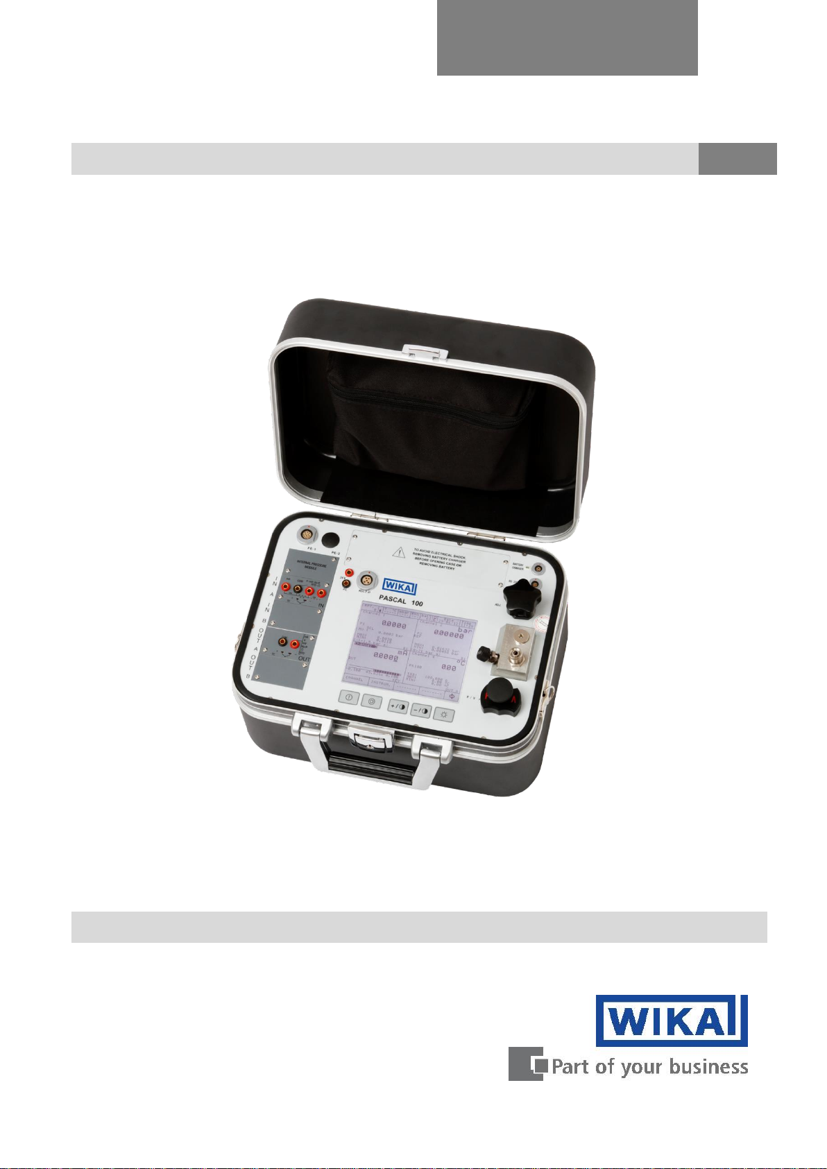
Multichannel Calibrator PASCAL 100 and PASCAL 100/IS
GB
Documenting Multivariable Multichannel Calibrator PASCAL100 / PASCAL100/IS
Operating instructions
Page 2

GB
Operating instructions PASCAL 100
Page
1 - 87
© 2012 WIKA Alexander Wiegand SE & Co. KG
All rights reserved.
WIKA® is a registered trademark in various countries.
Prior to starting any work, read the operating instructions!
Keep for later use!
2 WIKA Operating Instruction, Pascal 100 and Pascal 100/IS
Page 3

Contents
GB
1 General Information ............................................................................................................. 5
2 Safety .................................................................................................................................. 6
2.1 Intended use ........................................................................................................................ 7
2.2 Personnel qualification ......................................................................................................... 7
2.3 Additional safety instructions for instruments with ATEX approval only Pascal 100/IS ........ 8
2.4 Special hazards ................................................................................................................... 9
2.5 Labelling / safety marks ..................................................................................................... 10
3 Specifications ................................................................ .................................................... 11
4 Design and Function .......................................................................................................... 14
4.1 Description ........................................................................................................................ 14
4.2 Scope of delivery ............................................................................................................... 15
4.3 Power supply ..................................................................................................................... 15
5 Transport, packaging and storage ..................................................................................... 16
5.1 Transport ........................................................................................................................... 16
5.2 Packaging .......................................................................................................................... 16
5.3 Storage ................................................................................................ .............................. 16
6 Commissioning, operation ................................................................................................. 17
6.1 Commissioning .................................................................................................................. 17
6.1.1 Instrument Overview .......................................................................................................... 17
6.1.2 Functional Modules ........................................................................................................... 17
6.1.2.1 Input module for electrical/temperature signals ................................................. 18
6.1.2.2 Output module for electrical/temperature signals .............................................. 18
6.1.2.3 Pressure module............................................................................................... 19
6.1.2.4 HART module ................................................................ ................................... 20
6.1.2.5 Environmental parameters module (optional) .................................................... 22
6.2 Pressure ............................................................................................................................ 23
6.2.1 Pneumatic circuit ............................................................................................................... 23
6.3 Electrical ............................................................................................................................ 25
6.3.1 Electrical measurements ................................................................................................... 25
6.3.2 Thermocouple measurements ........................................................................................... 26
6.3.3 Thermoresistance measurements...................................................................................... 27
6.3.4 Generation of electrical parameters ................................................................................... 28
6.3.5 Thermocouple simulation ................................................................................................... 28
6.3.6 Thermoresistance simulation ............................................................................................. 29
6.4 User Interface .................................................................................................................... 30
6.4.1 Channel configuration ........................................................................................................ 31
6.4.2 Other assignments ............................................................................................................ 37
6.4.2.1 Pressure measurement..................................................................................... 37
6.4.2.2 Thermocouple signal measurement .................................................................. 41
6.4.2.3 Electrical parameter measurement ................................................................... 46
6.4.2.4 Temperature Simulation .................................................................................... 50
6.4.2.5 Electrical parameter generation ........................................................................ 50
6.4.2.6 Channel 4 – mathematic functions .................................................................... 51
6.4.2.7 HART channel assignment ............................................................................... 55
6.4.2.8 HART trimmer calibration .................................................................................. 58
6.4.2.9 HART scale adjust ............................................................................................ 60
6.5 Menu ................................................................................................................................. 61
6.5.1 Channel Menu ................................................................................................................... 62
6.5.2 Instrument Menu ................................................................................................................ 63
6.5.3 Report Menu ...................................................................................................................... 65
6.5.4 Engineering unit Menu ....................................................................................................... 65
6.5.5 Logger Menu ..................................................................................................................... 65
WIKA Operating Instruction, Model Pascal 100 and Pascal 100/IS 3
Page 4

Contents
GB
6.5.6 Calibration Menu ............................................................................................................... 65
6.5.7 Graph Menu ...................................................................................................................... 66
6.5.8 Ramp Menu ....................................................................................................................... 67
6.5.9 Disk Menu ......................................................................................................................... 69
6.6 Measurement Channel ...................................................................................................... 69
6.6.1 Status ................................................................................................................................ 70
6.6.2 Res. MxMn ........................................................................................................................ 70
6.6.3 Scaling .............................................................................................................................. 70
6.6.4 Filter .................................................................................................................................. 71
6.6.5 Hold On – Hold Off ............................................................................................................ 71
6.6.6 Offset On – Offset Off ........................................................................................................ 72
6.6.7 Inc. Dec – Dec. Dec ........................................................................................................... 72
6.6.8 Chg. Out ............................................................................................................................ 72
6.7 Report ............................................................................................................................... 74
6.8 Data Logger ....................................................................................................................... 79
6.9 Communication.................................................................................................................. 81
6.10 Calibration Examples ......................................................................................................... 82
6.10.1 Example 1 – Calibration of two wires pressure transmitters ............................................... 82
6.10.2 Example 2 – Calibration of PTZ gas volume converters ..................................................... 83
6.10.3 Example 3 – Calibration of four wires RTD’s ...................................................................... 84
6.10.4 Example 4 – Calibration of Thermocouples ....................................................................... 85
7 Maintenance, cleaning and servicing ................................................................................. 86
7.1 Maintenance ...................................................................................................................... 86
7.2 Cleaning ............................................................................................................................ 86
7.3 Recalibration ..................................................................................................................... 86
8 Dismounting, return and disposal ...................................................................................... 87
8.1 Dismounting ...................................................................................................................... 87
8.2 Return ............................................................................................................................... 87
8.3 Disposal ............................................................................................................................ 87
Appendix 1: ATEX Approval of Pascal 100/IS ............................................................................... 88
Declarations of conformity can be found online at www.wika.com.
4 WIKA Operating Instruction, Pascal 100 and Pascal 100/IS
Page 5

1 General Information
GB
1 General Information
■ The Multichannel Calibrator model Pascal 100 or Pascal 100/IS described in the operating
instructions has been manufactured using state-of-the-art technology.
All components are subject to stringent quality and environmental criteria during production. Our
management systems are certified to ISO 9001 and ISO 14001.
■ These operating instructions contain important information on handling the Multichannel
Calibrator model Pascal 100 or Pascal 100/IS. Working safely requires that all safety instructions
and work instructions are observed.
■ Observe the relevant local accident prevention regulations and general safety regulations for the
range of use of the Multichannel Calibrator model Pascal 100 or Pascal 100/IS.
■ The operating instructions are part of the instrument and must be kept in the immediate vicinity
of the Multichannel Calibrator model Pascal 100 or Pascal 100/IS and readily accessible to
skilled personnel at any time.
■ Skilled personnel must have carefully read and understood the operating instructions, prior to
beginning any work.
■ The manufacturer's liability is void in the case of any damage caused by using the product
contrary to its intended use, non-compliance with these operating instructions, assignment of
insufficiently qualified skilled personnel or unauthorised modifications to the Pascal 100 or
Pascal 100/IS.
■ The general terms and conditions, contained in the sales documentation, shall apply.
■ Subject to technical modifications.
■ Factory calibrations/DKD/DAkks calibrations are carried out in accordance with international
standards.
■ Further information:
- Internet address: www.wika.de / www.wika.com
- Relevant Data Sheet: CT 18.01
- Application consultant: Tel.: (+49) 9372/132-9986
Fax: (+49) 9372/132-8767
E-Mail: testequip@wika.de
WIKA Operating Instruction, Model Pascal 100 and Pascal 100/IS 5
Page 6
1 General Information / 2 Safety
GB
Explanation of symbols
WARNING!
... indicates a potentially dangerous situation, which can result in serious
injury or death, if not avoided.
Information
... points out useful tips, recommendations and information for efficient and
trouble -free operation.
WARNING!
... indicates a potentially dangerous situation in a potentially explosive
atmosphere, resulting in serious injury or death, if not avoided.
2 Safety
WARNING!
Before installation, commissioning and operation, ensure that the appropriate
reference pressure sensor has been selected in terms of measuring range, design and
specific measuring conditions. Serious injuries and/or damage can occur should these
not be observed.
Further important safety instructions can be found in the individual chapters of these
operating instructions.
6 WIKA Operating Instruction, Pascal 100 and Pascal 100/IS
Page 7
2 Safety
GB
2.1 Intended use
The Multichannel Calibrator model Pascal 100 or Pascal 100 IS gauge can be used as a
calibration instrument and also for any application which requires accuracy pressure measurement.
The Multichannel Calibrator model Pascal 100 or Pascal 100/IS has been designed and built solely
for the intended use described here, and may only be used accordingly.
The technical specifications contained in these operating instructions must be observed.
Improper handling or operation of the Multichannel Calibrator model Pascal 100 or Pascal 100/IS
outside of its technical specifications requires the instrument to be shut down immediately and
inspected by an authorised WIKA service engineer.
Handle electronic precision measuring instruments with the required care (protect from strong
magnetic fields, static electricity and extreme temperatures, do not insert any objects into the
instrument or its openings). Plugs and sockets must be protected from contamination.
If the Multichannel Calibrator model Pascal 100 or Pascal 100/IS is transported from a cold into a
warm environment, the formation of condensation may result in the instrument malfunctioning.
Before putting it back into operation, wait for the instrument temperature and the room temperature
to equalise.
The manufacturer shall not be liable for claims of any type based on operation contrary to the
intended use.
2.2 Personnel qualification
WARNING!
Risk of injury should qualification be insufficient!
Improper handling can result in considerable injury and damage to equipment.
■The activities described in these operating instructions may only be carried out by
skilled personnel who have the qualifications described below.
Skilled personnel
Skilled personnel are understood to be personnel who, based on their technical training,
knowledge of measurement and control technology and on their experience and knowledge of
country-specific regulations, current standards and directives, are capable of carrying out the work
described and independently recognising potential hazards.
Special operating conditions require further appropriate knowledge, e.g. of aggressive media.
WIKA Operating Instruction, Model Pascal 100 and Pascal 100/IS 7
Page 8
2 Safety
GB
II 2G
Ex ib IIC T4 Gb - Tamb: -10°C / 50°C
2.3 Additional safety instructions for instruments with ATEX approval
only Pascal 100/IS
WARNING!
Non-observance of these instructions and their contents may result in the loss of
explosion protection.
■ Battery operation:
Use only the rechargeable battery which is supplied by WIKA! Only charge the
battery outside of the hazardous area!
■ Operation of the serial interface in the hazardous area is prohibited.
Further hazardous area safety instructions!
Observe the operating information and the relevant country-specific regulations
concerning use in hazardous areas (e.g. EN IEC 60079-14).
The Pascal 100/IS intrinsically safe multichannel calibrator has been designed for
use in Ex Hazardous Areas. These are areas where potentially flammable or
explosive vapors may occur. These areas are referred to as hazardous (classified)
locations in the United States, as Hazardous Locations in Canada, as Potentially
Explosive Atmospheres in Europe and as Explosive Gas Atmospheres by most of
the rest of the world. The Pascal 100/IS intrinsically safe multichannel calibrator is
designed as intrinsically safe. This means that connecting the Pascal 100/IS
intrinsically safe multichannel calibrator to equipment that is used within intrinsically
safe circuits will not cause an ignition capable arc as long as the entity parameters
are suitably matched.
Information/Approval for hazardous locations:
WARNING!
■ Ex Hazardous Areas
An Ex-hazardous area as used in this manual refers to an area made hazardous
by the potential presence of flammable or explosive vapors. These areas are also
referred to as hazardous locations.
WARNING!
Only gauges powered by batteries are approved for use in hazardous locations.
Use only the rechargeable battery which is supplied by WIKA! Only charge the
battery outside of the hazardous area!
8 WIKA Operating Instruction, Pascal 100 and Pascal 100/IS
Page 9

2 Safety
GB
2.4 Special hazards
WARNING!
■ When measuring pressure, make sure that the process pressure line is shut off
and depressurised before it is connected to or disconnected from the pressure
module.
■Disconnect test leads before changing to another measurement or generation
function.
■ Observe the working conditions in accordance with chapter "3. Specifications".
■ Always operate the device within its overload limits.
■ To ensure problem-free operation, only operate the Multichannel Calibrator
model Pascal 100 or Pascal 100/IS on battery power. Only use the mains
connection for charging the Hand-held pressure calibrators batteries.
■ Do not apply a voltage greater than the specified voltage to the instrument.
See chapter "3. Specifications".
■ Make sure that the test probes never contact a voltage source while the test
leads are connected to the current terminals.
■ Do not use the calibrator if it is damaged. Before using the multichannel
calibrator, check that there are no cracks or missing plastic parts on the case.
Pay particular attention to the insulation of the connectors.
■ Select the proper function and correct measuring range for the measurement.
■ Inspect the test leads for damaged insulation or exposed metal. Check the
continuity of the test leads. Damaged test leads should be replaced before using
the multichannel calibrator.
■ When using test probes keep fingers away from the test probe contacts. Keep
your fingers behind the test probes' finger guards.
■ First connect the common lead, and then the live lead. When disconnecting,
remove the live test lead first.
■ Do not use the multichannel calibrator if it is not working properly. The
instrument protection might be compromised. If in doubt, have the instrument
checked.
■ Do not operate the calibrator in areas with explosive gases, vapours or dust.
■ To avoid false readings, which could lead to possible electric shock or personal
injury, charge the rechargeable battery as soon as the battery indicator appears.
■ In order to avoid any possible damage to the multichannel calibrator or the test
equipment, use the correct leads, the correct function and the correct range for
the measuring application.
WIKA Operating Instruction, Model Pascal 100 and Pascal 100/IS 9
Page 10
2 Safety
GB
2.5 Labelling / safety marks
Explanation of symbols
Pascal 100 and Pascal 100/IS
Before mounting and commissioning the Multichannel Calibrator model
Pascal 100 or Pascal 100/IS, ensure you read the operating instructions!
CE, Communauté Européenne
Instruments bearing this mark comply with the relevant European directives.
This marking on the instruments indicates that they must not be disposed of in
domestic waste. The disposal is carried out by return to the manufacturer or by
the corresponding municipal authorities. See Directive 2002/96/EC.
Only Pascal 100/IS
ATEX European Explosion Protection Directive
(Atmosphère = AT, explosible = Ex)
Instruments bearing this mark comply with the requirements of the European
Directive 94/9/CE (ATEX) on explosion protection.
10 WIKA Operating Instruction, Pascal 100 and Pascal 100/IS
Page 11
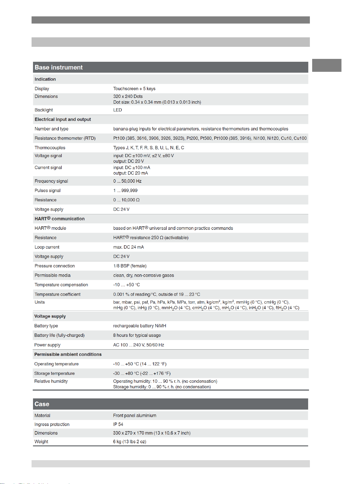
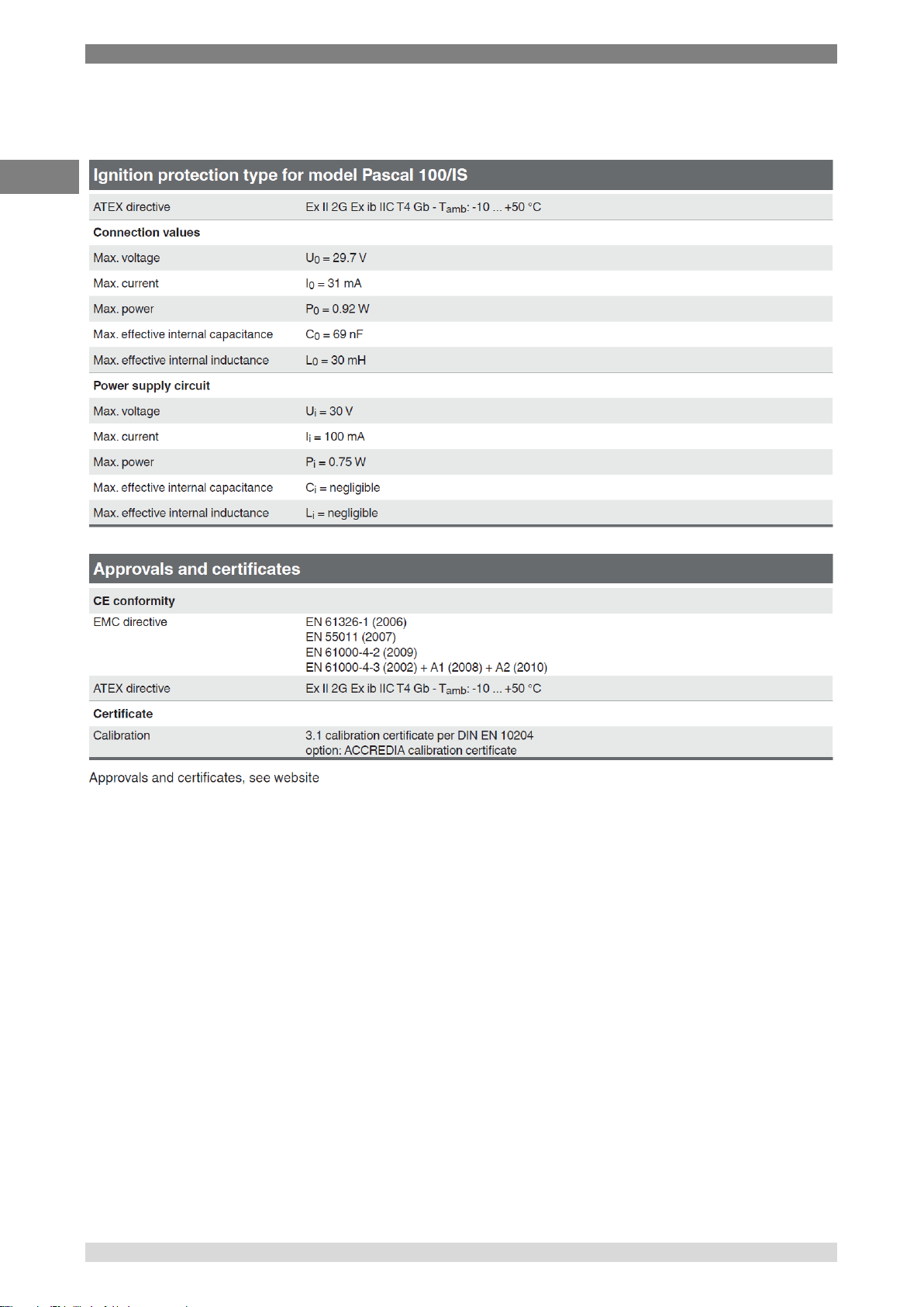
3 Specifications
GB
1)
3 Specifications
WIKA Operating Instruction, Model Pascal 100 and Pascal 100/IS 11
Page 12
3 Specifications
GB
12 WIKA Operating Instruction, Pascal 100 and Pascal 100/IS
Page 13
3 Specifications
GB
For further specifications see WIKA data sheet CT 18.01 and the order documentation.
WIKA Operating Instruction, Model Pascal 100 and Pascal 100/IS 13
Page 14

4 Design and Function
GB
4 Design and Function
4.1 Description
Pascal 100 or Pascal 100/IS is the Professional Advanced Scandura Calibrator of latest
generation.
User friendly interface by a wide display with an industrial touch screen through which it is possible
to manage the instrument completely.
The operations are simplified thanks to the touch screen: the display changes in a dynamic way
according to the user selections, following test by step the operator during the calibration process,
decreasing the learning time and the human errors.
The touch screen can be operated by nude or gloved hands: dirty parts can be easily removed with
a cloth or a sponge. The touch screen can be locked during the measurement process to avoid
unintentional pressing of keys
The backlight illumination with LED guarantees a perfect view in case of low environmental
visibility.
Five keys are present below the touch screen : turn on/off of the instrument, contrast settings and
backlight.
Pascal 100 or Pascal 100/IS consists of two parts: pressure part and electrical one.
The pressure part consists of:
■ 1 a pneumatic distribution block
■ 2 internal manual vacuum/pressure generator with fine adjustment
■ 3 up to four internal pressure sensors with overpressure valves.
The electrical part consists of up to four electrical module (2 input (IN) and 2 output (OUT) for the
measurement and generation of mA, mV, V, Hz, Ohm, Pulse, TC/RTD.
On the front panel of the instrument there are several connectors for:
■ recharging the battery
■ RS232 port
■ Connection to the external pressure transducers
■ Connection for the environment parameters
(temperature, humidity and atmospheric pressure)
Moreover there are the connections to provide 24 V d.c. power supply to the device under test.
The Pascal 100 or Pascal 100/IS is powered with an internal battery pack. The battery allows 8
hours of standard operation before recharging.
Operating Pascal 100 or Pascal 100/IS user is able to calibrate the whole industrial instrumentation
like for example:
■ Electronic and pneumatic pressure/vacuum transmitter
■ Electronic and pneumatic differential pressure transmitter
■ Electronic and pneumatic temperature transmitter (thermocouple and RTD)
■ Signal converter V, mV, mA, Hz, Pulse, ohm
■ Signal converter I/P and P/I
■ Signal isolator mA, mV
■ Mathematical Device (adder, subtractor, multiplier, divider)
■ Manometer, Pressure switch
■ Temperature monitor switch
■ Thermocouple and thermoresistance
■ Compensation device (up to 4 in-out signals)
■ Electronic and pneumatic receiver
■ Electronic and pneumatic controller
■ Electronic and pneumatic recorder
■ Miscellaneous instrument
14 WIKA Operating Instruction, Pascal 100 and Pascal 100/IS
Page 15
4 Design and Function
GB
Pascal 100 or Pascal 100/IS includes different modules and can be ordered with different hardware
configurations.
The hardware configuration depends on the installation of different functional modules:
■ Two electrical/temperature IN modules (IN A & IN B)
■ Two electrical/temperature OUT modules (OUT A & OUT B)
■ Two pressure modules
(each one can support two internal and one external transducer. Total 6 sensors)
■ One environment parameters module
(atmospheric pressure, ambient temperature and relative humidity)
■ One power supply 24 V d.c.
■ One RS-232 communication port
■ One connection for recharging the battery
■ One hand pump for pressure or vacuum generation
■ One fine adjustment for a good regulation of pressure or vacuum
■ One set of valves for sensor protection against overpressure
Battery Life
In order to preserve battery life is recommended to keep the battery charger
connected for no more than 36 hours
Functional module
A functional module is a hardware component that allows the Pascal 100 or
Pascal 100/IS to perform some operations like for example measurement and
generation of electrical signals and pressure.
4.2 Scope of delivery
■ Portable multifunction calibrator model Pascal 100 or Pascal 100/IS
■ Operating instructions
■ AC adapter
■ Pascal report software
■ RS-232 interface cable
■ RS-232 to USB adapter
■ Electrical kit order no. 241076
■ Pneumatic pressure kit order no. 241028 and 241029
(Depending on pressure range)
■ 3.1 calibration certificate per DIN EN 10204
Cross-check scope of delivery with delivery note.
4.3 Power supply
Charging
To avoid false measurements, charge the rechargeable batteries as soon as the battery indicator
appears. If the batteries run too low the Pascal 100 or Pascal 100/IS will automatically shut down.
Use only the original AC/DC converter which is supplied by WIKA
WIKA Operating Instruction, Model Pascal 100 and Pascal 100/IS 15
Page 16

5 Transport, packaging and storage
GB
5 Transport, packaging and storage
5.1 Transport
Check the Multichannel Calibrator model Pascal 100 or Pascal 100/IS for any damage that may
have been caused by transport. Obvious damage must be reported immediately.
5.2 Packaging
Do not remove packaging until just before mounting.
Keep the packaging as it will provide optimum protection during transport (e.g. sending for
calibration).
5.3 Storage
Permissible conditions at the place of storage:
■ Storage temperature: -30 ... +80 °C
■ Relative Humidity: 10 ... 90 % r. H. (non-condensing)
Avoid exposure to the following factors:
■ Direct sunlight or proximity to hot objects
■ Mechanical vibration, mechanical shock (putting it down hard)
■ Soot, vapour, dust and corrosive gases
■ Potentially explosive environments, flammable atmospheres
Store the instrument in its original packaging in a location that fulfills the conditions listed above. If
the original packaging is not available, pack and store the instrument as described below:
1. Wrap the instrument in an antistatic plastic film.
2. Place the instrument, along with shock-absorbent material, in the packaging.
3. If stored for a prolonged period of time (more than 30 days), place a bag, containing a
desiccant, inside the packaging.
16 WIKA Operating Instruction, Pascal 100 and Pascal 100/IS
Page 17
6 Commissioning, operation
GB
3
4
5
6
7
8
12
10
11
1
2 9 13
14
15
16
17
6 Commissioning, operation
6.1 Commissioning
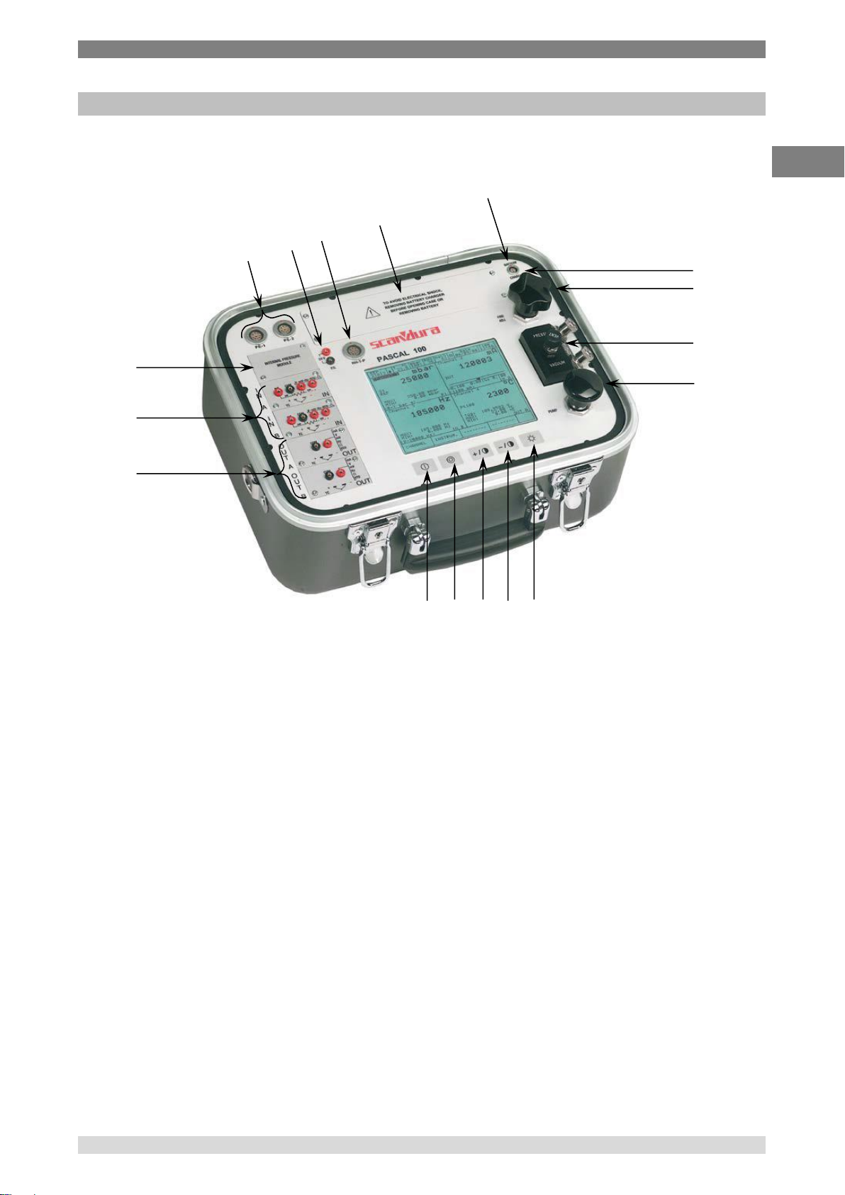
6.1.1 Instrument Overview
1 Connectors for external P transducer 10 Hand pump (vacuum/21 bar)
2 Pressure modules 11 Pneumatic distribution
3 IN electrical/temperature modules 12 Fine adjustment
4 OUT electrical/temperature modules 13 Connector RS-232
5 Power ON 14 Connector for battery charger
6 Power OFF 15 Battery
7 Contrast + 16 Environmental Parameter Connector
8 Contrast – 17 Loop power supply – 24 V d.c.
9 Back light OFF (Lamp)
6.1.2 Functional Modules
The functional modules can be classified according to their assignments:
■ Electrical and temperature signals measurement
■ Pressure measurement, (2 different modules, up to 4 internal pressure sensors and 2
connectors for external pressure sensor)
■ Electrical and temperature signals generation/simulation
■ Pressure generation and regulation
■ Environmental parameters measurement
Many different configurations are available according to the specific requirements of the user.
WIKA Operating Instruction, Model Pascal 100 and Pascal 100/IS 17
Page 18
6 Commissioning, operation
GB
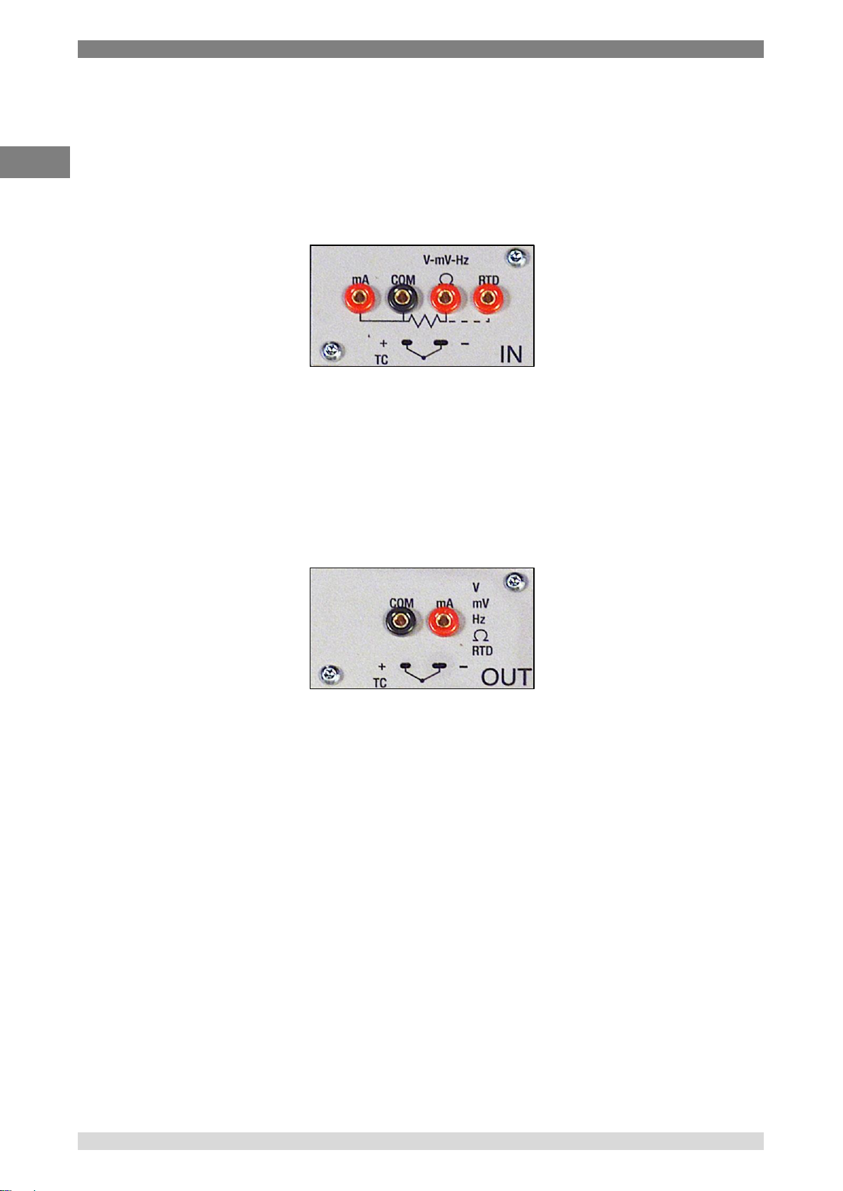
6.1.2.1 Input module for electrical/temperature signals
The input module for electrical/temperature parameters measurement is one of those modules
inserted from the instrument’s front panel; two slides drive the module into its position. It is possible
to have up to two input modules in the same instrument: IN A and IN B. This terminology is used
also by the software to carry out the connection between physical input IN and software channel.
For example: if you connect a thermoresistance Pt100 to module IN A, the temperature measured
by this thermoresistance can be displayed in any of the four software channels available. The
following figure shows the pins connection in electrical/temperature IN module.
Figure 1 – Input panel module
6.1.2.2 Output module for electrical/temperature signals
The output module for electrical/temperature parameters generation or simulation is one of those
inserted from the instrument’s front panel; two slides drive the module into its position. It is possible
to have up to two output modules in the same instrument: OUT A and OUT B. This terminology is
used also by the software to carry out the connection between physical output OUT and software
channel. For example: if you connect a signal-receiver to module output OUT A, the current 4…20
mA generated can be displayed in any of the four software channels available.
The following figure shows the output module for electrical/temperature parameters.
Figure 2 – Output panel module
The 2 INPUT cards and 2 OUTPUT cards are plug and play modules and can be installed by the
user himself.
18 WIKA Operating Instruction, Pascal 100 and Pascal 100/IS
Page 19

6 Commissioning, operation
GB
Range
Precision (% FS)
Accuracy (% FS)
Typical Resolution
Gauge
-60…+60 mbar
0,08
0,1
0,01 mbar
-500…+500 mbar
0,015
0,025
0,01 mbar
-900…+1500 bar
0,015
0,025
0;01 mbar
0…7 bar
0,015
0,025
0,1 mbar
0…21 bar
0,015
0,025
0;1 mbar
0…50 bar
0,015
0,025
1 mbar
0…100 bar
0,015
0,025
1 mbar
Absolute
600…1300 mbar abs.
0,015
0,025
0,01 mbar
0…1500 mbar abs.
0,015
0,025
0,01 mbar
0…2500 mbar abs
0,015
0,025
0,01 mbar
0…2500 mbar abs
0,010
0,015
0,01 mbar
0…5 bar abs.
0,015
0,025
0,1 mbar
0…7 bar abs.
0,015
0,025
0,1 mbar
0…21 bar abs.
0,015
0,025
0,1 mbar
0…81 bar abs.
0,015
0,025
1 mbar
0…100 bar abs.
0,015
0,025
1 mbar
Range
Precision (% FS)
Accuracy (% FS)
Typical Resolution
Gauge
-60…+60 mbar
0,1
0,15
0,01 mbar
-500…+500 mbar
0,015
0,025
0,01 mbar
-900…+1500 bar
0,015
0,025
0;01 mbar
0…7 bar
0,015
0,025
0,1 mbar
0…21 bar
0,015
0,025
0;1 mbar
0…50 bar
0,015
0,025
1 mbar
0…100 bar
0,015
0,025
1 mbar
0…200 bar
0,015
0,025
10 mbar
0…400 bar
0,015
0,025
100 mbar
0…700 bar
0,025
0,05
100 mbar
0…1000 bar
0,025
0,05
100 mbar
Absolute
0…1500 mbar abs.
0,015
0,025
0,01 mbar
0…2500 mbar abs
0,015
0,025
0,01 mbar
0…5 bar abs.
0,015
0,025
0,1 mbar
0…7 bar abs.
0,015
0,025
0,1 mbar
0…21 bar abs.
0,015
0,025
0,1 mbar
0…81 bar abs.
0,015
0,025
1 mbar
0…100 bar abs.
0,015
0,025
1 mbar
6.1.2.3 Pressure module
The pressure module is installed only at factory location in accordance with the Pascal 100 or
Pascal 100/IS configuration required. It is possible to install two pressure modules, each one can
support up to two internal and one external transducers. In total Pascal 100 can accommodate four
internal and two external transducers. Transducer’s selection with range and their resolutions are
in the following table. If requested, one of the standard pressure modules can be changed with one
high accuracy pressure module (with one high accuracy transducer).
Internal transducers *
External transducers *
* Other ranges available on request
WIKA Operating Instruction, Model Pascal 100 and Pascal 100/IS 19
Page 20
6 Commissioning, operation
GB
Transmitter
HART slave
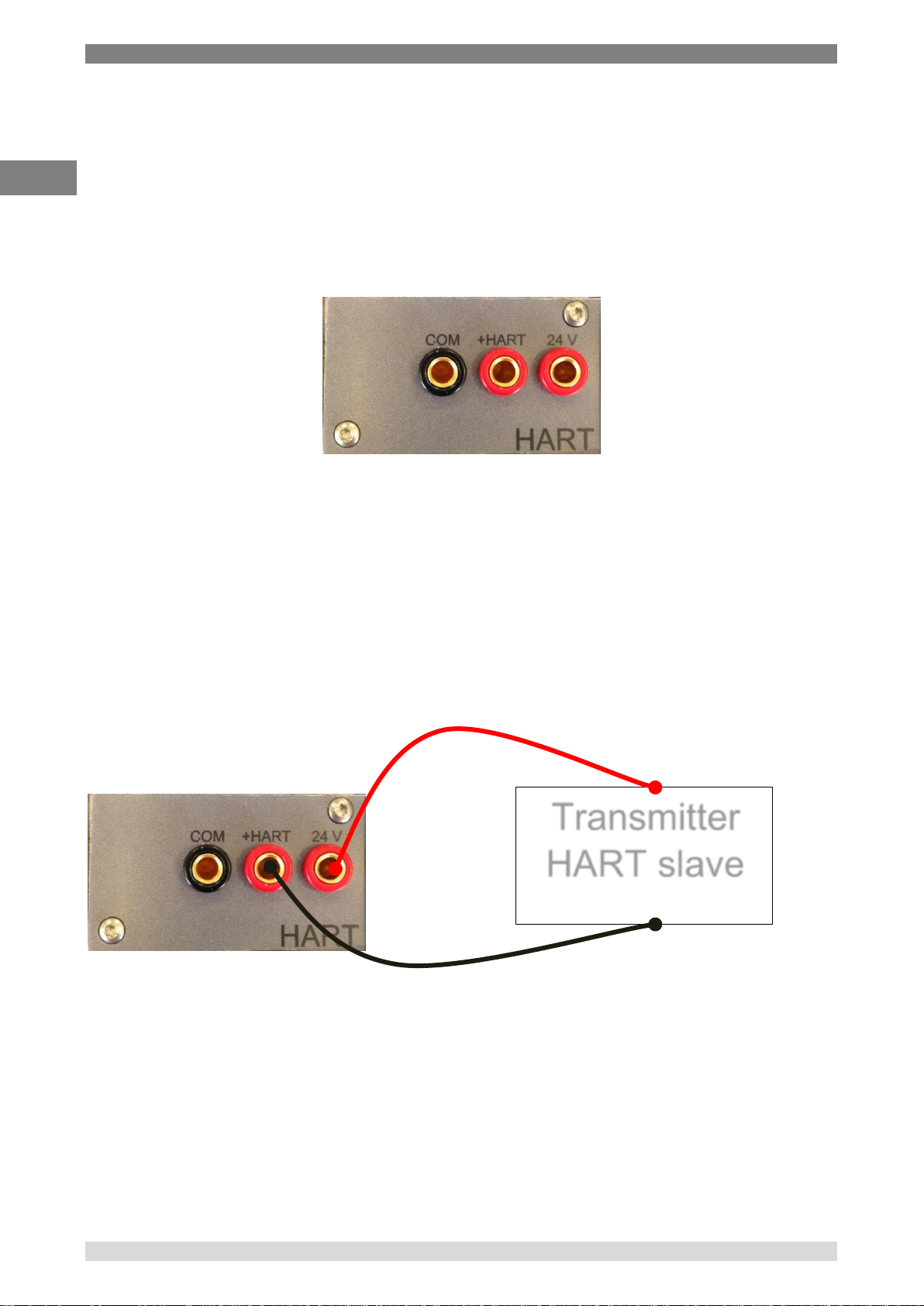
6.1.2.4 HART module
The HART module allows communication with HART instruments (usually transmitters) permitting
to acquire digital measurements, instrument data and modifying settings. It can be inserted in the
front panel in place of OUT A or OUT B module.
It is a fully galvanically isolated board (like IN and OUT modules) from internal electronics of the
Pascal.
The module allow the 24V to supply directly the output loop for the transmitter.
Further, it can supply a 250Ω load resistance electronically switchable necessary to HART
communication, permitting to avoid the use of an external one.
The following figure shows the pin connections in HART module:
Figure 3 – HART module
6.1.2.4.1 HART wiring
Depending by several factors and combination that the user can found in a plant, there are many
wiring possibility depending by:
Using module internal or external Power Supply.
Using internal or external load resistance.
Simultaneous analog connection of AO TRX to one Input module for mA reading
Please consider, if the user enable the internal load resistance, this will be connected between the
+HART and COM terminals.
Here same examples:
20 WIKA Operating Instruction, Pascal 100 and Pascal 100/IS
Figure 4 - Case 1: 24V from module, 250Ω from module
Page 21
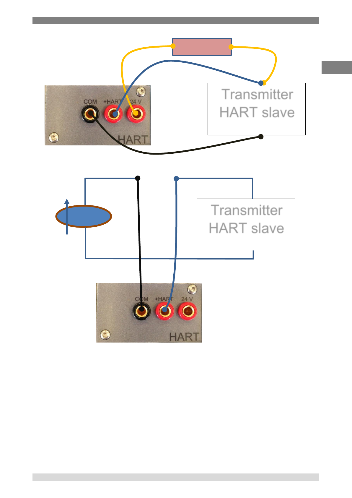
6 Commissioning, operation
GB
Transmitter
HART slave
250 Ω
Transmitter
HART slave
24V ext.
Figure 5 - Case 2: 24V from module, 250Ω external
WIKA Operating Instruction, Model Pascal 100 and Pascal 100/IS 21
Figure 6 - Case 3: 24V external, 250Ω from module
Page 22
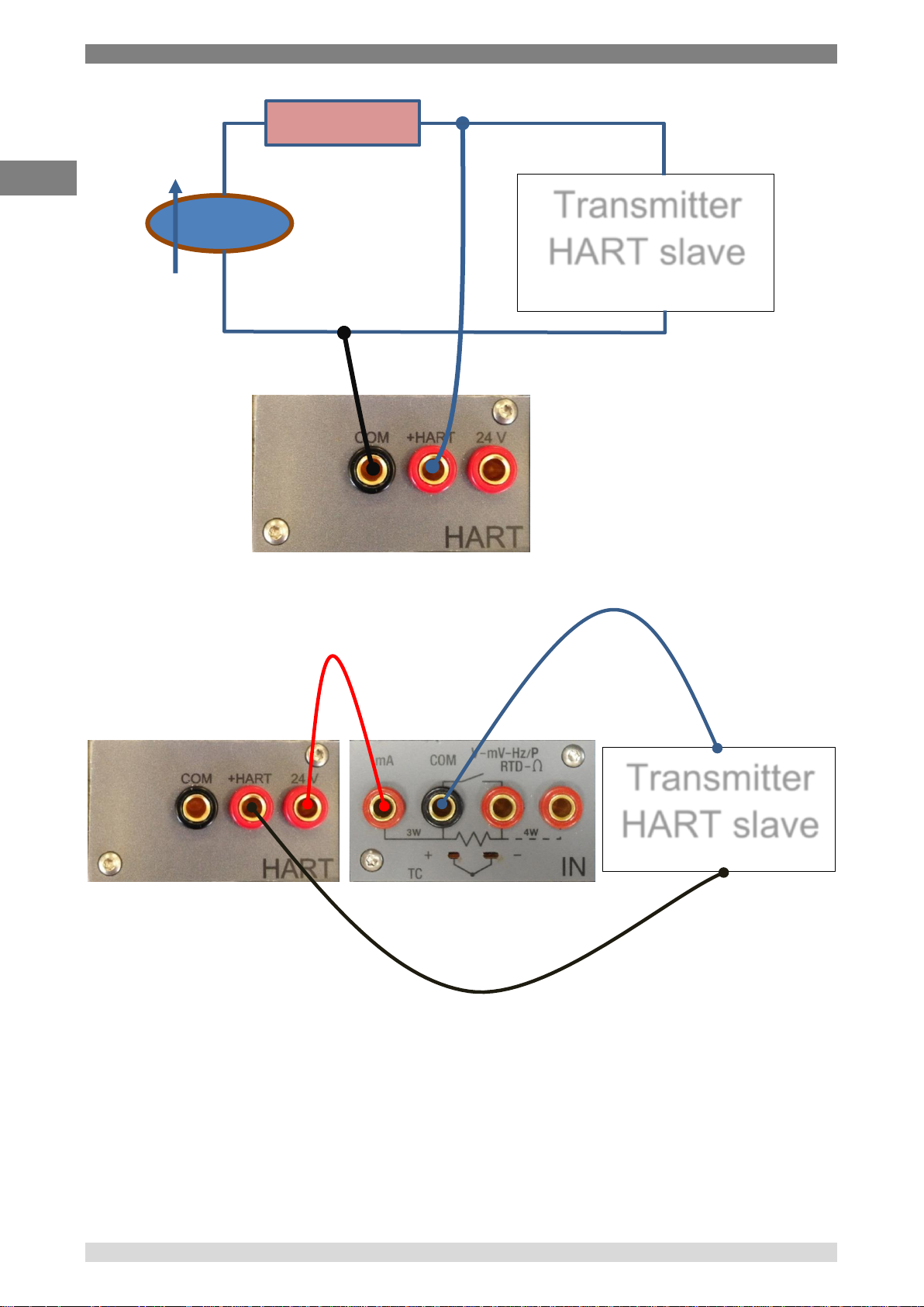
6 Commissioning, operation
GB
Transmitter
HART slave
24V ext.
250 Ω
Transmitter
HART slave
Figure 7 - Case 4: 24V external, 250Ω external
Figure 8 - Case 5: 24V from module, 250Ω from module, mA reading by IN module
6.1.2.5 Environmental parameters module (optional)
This module allows to measure: temperature, relative humidity and atmospheric pressure. These
parameters represent the most important factors that affect the calibration results. This module is
connected to Pascal 100 or Pascal 100/IS with a multiple pin connector present in
Pascal 100 or Pascal 100/IS front panel. This module is plug & play and the relevant information
about the environmental parameters are displayed on the status bar at the top of the screen.
This information is automatically reported on the calibration report.
22 WIKA Operating Instruction, Pascal 100 and Pascal 100/IS
Page 23
6 Commissioning, operation
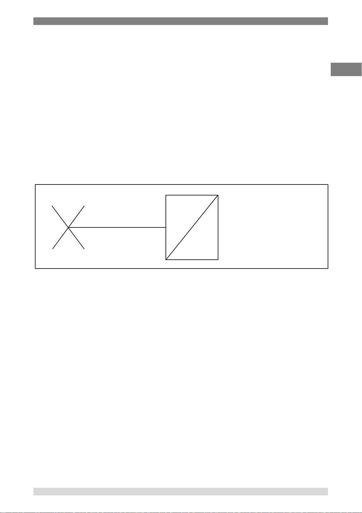
GB
Direct transducer
6.2 Pressure
6.2.1 Pneumatic circuit
Pascal 100 or Pascal 100/IS can be equipped with four internal and two external pressure sensors.
The internal sensors work only with clean dry gas (like dry air) whereas the external sensors can
work with gas or liquid. Gas is related to pneumatic circuit and liquid to hydraulic circuits.
Pascal 100 or Pascal 100/IS has a pneumatic circuit that gives possibility to execute a large
number of calibration in an easy way for connecting the device under test. An integrated pump and
a fine adjustment allow to generate the required pressure. The generated pressure, according to
the model, can be distributed in parallel to all sensors. The sensors whose ranges are much lower
than the maximum pressure generated in the pneumatic circuit are protected from overpressure by
a mechanical valve that closes the circuit when the pressure gets over its range.
Switching the pressure-vacuum selector in the vacuum position is possible to generate vacuum
(pressure under the barometric)
For example, if we want to measure a signal from pneumatic instrument 3 - 15 PSI or to measure
high gas pressure over 21 bar and we use an internal sensor directly connected to the process, we
must pay attention not to damage it by applying pressure over its range.
Figure 9 – Direct transducer
WIKA Operating Instruction, Model Pascal 100 and Pascal 100/IS 23
Page 24
6 Commissioning, operation
GB
Transducer 1
Transducer 2
Overpressurevalve
Transducer 1
Pressure- Vacuum
variator
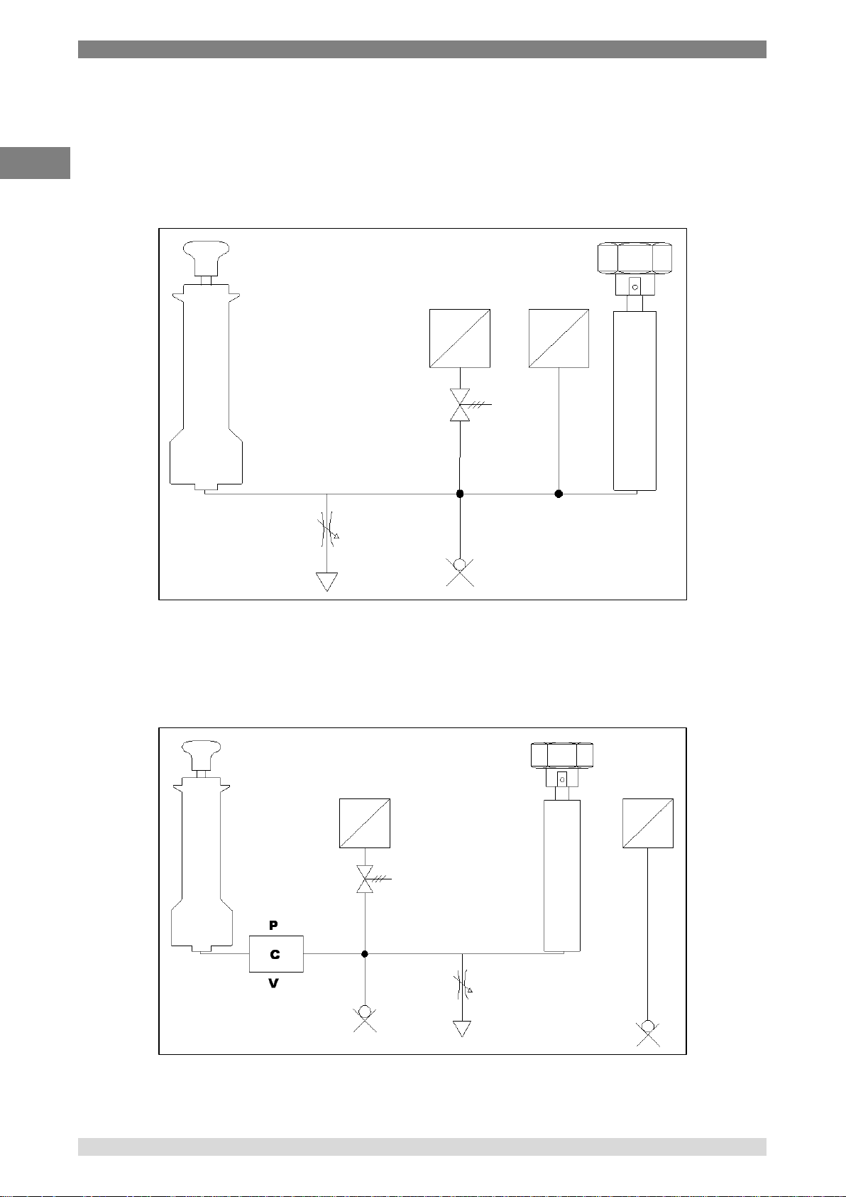
There are three different pneumatic schemes available in a standard Pascal 100 or
Pascal 100/IS configuration:
■ This is an example of pneumatic circuit with two sensors in parallel to the pump. One of
them is protected by an overpressure valve, the other one is not protected because it has a
full-scale equal to the maximum pressure generated by the pump. See following:
Figure 10 – Circuit with two sensors in parallel
■ This is an example of pneumatic circuit with two sensors: one sensor connected in parallel
to the pump with over pressure protection, and one sensor directly connected for
measuring the external pressure signals without overpressure protection. See following:
24 WIKA Operating Instruction, Pascal 100 and Pascal 100/IS
Figure 11 - Circuit with transducer connected to process
Page 25
6 Commissioning, operation
GB
Range
Max resolution
Voltage
(-100…100) mV
0,0001 mV
(-2…2) V
0,000001 V
(-80…80) V
0,00001 V
Current
(-100…100) mA
0,0001 mA
Resistance
(0…400) Ω
0,001 Ω
(0…10000) Ω
0,01 Ω
Frequency
(0,4…50000) Hz
0,001 Hz
Pulse
0,4…20 Hz
-
Contact
Open - Closed
-
Pressure-
Vacuum variator
Transducer 1
Transducer 2
Transducer 3
Transducer 4
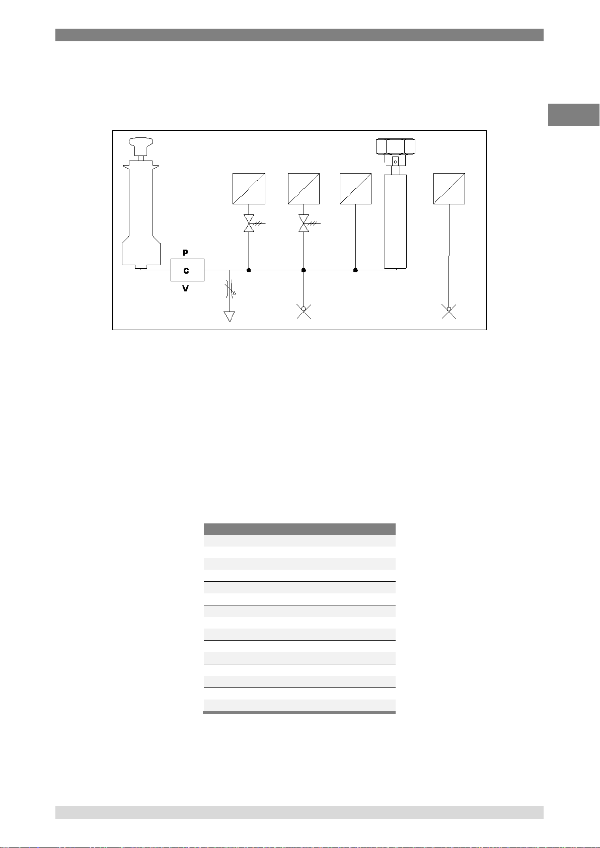
■ This is an example of pneumatic circuit with four sensors: three of them are connected in
parallel to the pumps and one straight to external. Two of them are protected by
overpressure valves, the other one is not protected because it has its full-scale equal to the
maximum pressure generated by pump. See following:
Figure 12 - Circuit with four transducers
6.3 Electrical
The Pascal 100 or Pascal 100/IS is a multifunction calibrator.
The electrical modules can be maximum four, two of them are input modules (IN A – IN B), and the
other two are output modules (OUT A – OUT B).
6.3.1 Electrical measurements
The instrument is able to measure voltage, current, resistance and frequency. To optimise the
resolution and get better measurement results, there are three ranges for voltage measurement,
two for resistance measurements, one range for current and three ranges for frequency.
Ranges of measurement and resolutions are specified in following table:
WIKA Operating Instruction, Model Pascal 100 and Pascal 100/IS 25
Table 1 - Range of input signals
Page 26

6 Commissioning, operation
GB
Type
Range/°C
Resolution/°C
Max
J
-210…1200
0,1
-190…1200
0,01
K
-270…1370
0,1
-160…1260
0,01
T
-270…400
0,1
-130…400
0,01
F
0…1400
0,1
0…1400
0,01
R
-50…1760
0,1
150…1760
0,01
S
-50…1760
0,1
170…1760
0,01
B
50…1820
0,1
920...1820
0,01
U
-200…400
0,1
-160…400
0,01
L
-200…760
0,1
-200…760
0,01
N
-270…1300
0,1
0…1300
0,01
E
-270…1000
0,1
-200…1000
0,01
C
0…2300
0,1
0…2000
0,01
M
-50…1410
0,1
-50…1410
0,01
6.3.2 Thermocouple measurements
The electrical module measures signals from the thermocouple and shows it in different
engineering units (°C, °F, K).
Thermocouple types, measuring range, linearity error and related resolutions are given in the
following table:
Table 2 – Thermocouple measurements table
It is possible to perform the measurement in two different ways: with internal reference (cold
junction), with external reference cold junction by entering the reference value through the
keyboard. When internal reference cold junction is selected, the ambient temperature is measured
through the thermocouple pins using a special thermo resistance. This temperature value is used
for compensation. The Standard connector Mignon for thermocouple is shown in Figure 1. The
thermoresistance for compensation of the reference cold junction is integrated in the same
connector.
26 WIKA Operating Instruction, Pascal 100 and Pascal 100/IS
Page 27

6 Commissioning, operation
GB
Type
Range/°C
Resolution/°C
Max
Pt100 (385)
-200…850
0,1
-200…850
0,01
Pt100 (3916)
-200…850
0,1
-200…850
0,01
Pt100 (3926)
-200…850
0,1
-200…850
0,01
Pt100 (3902)
-200…650
0,1
-200…650
0,01
Pt100 (3923)
-200…600
0,1
-200…600
0,01
Pt100 JIS (3916)
-200…600
0,1
-200…600
0,01
Pt200 (385)
-200…850
0,1
-200…850
0,01
Pt500 (385)
-200…850
0,1
-200…530
0,01
Pt1000 (385)
-200…850
0,1
-200…850
0,01
Pt1000 (3916)
-200…850
0,1
-200…850
0,01
Ni100 (617)
-60…180
0,1
-60…180
0,01
Ni120 (672)
0…150
0,1
0…150
0,01
Cu10 (42)
-70…150
0,1
-70…150
0,01
Cu100
-180…150
0,1
-180…150
0,01
6.3.3 Thermoresistance measurements
The electrical module measures signals from thermoresistance and shows it in different
engineering units (°C, °F, K).
Thermoresistance types, measuring range and related resolutions are given in the following table:
Table 3 - Thermoresistance measurements table
It is possible to connect the thermoresistance according to the type of measurement: 2 wires, 3
wires and 4 wires. The two wires measurement is performed without any compensation of the
connecting cables resistances; in this case the connection is among the two central (COM - Ω)
pins. In the case of three wires connection the pin identified with the writing 3W must also be used.
While for the four wires measurement, the most accurate of the above, is performed by using all
four pins.
WIKA Operating Instruction, Model Pascal 100 and Pascal 100/IS 27
Page 28

6 Commissioning, operation
GB
Range
Max resolution
Voltage
(0…100) mV
0,0001 mV
(0…2) V
0,000001 V
(0…20) V
0,00001 V
Current
(0…20) mA
0,0001 mA
Resistance
(0…400) Ω
0,001 Ω
(0…10000) Ω
0,01 Ω
Frequency
(0,5…20000) Hz
0,001 Hz
Pulse
(0,5…200) Hz / 9999999 impulse
Type
Range/°C
Resolution/°C
Max
J
-210…1200
0,1
-190…1200
0,01
K
-270…1370
0,1
-160…1260
0,01
T
-270…400
0,1
-130…400
0,01
F
0…1400
0,1
0…1400
0,01
R
-50…1760
0,1
150…1760
0,01
S
-50…1760
0,1
170…1760
0,01
B
50…1820
0,1
920…1820
0,01
U
-200…400
0,1
-160…400
0,01
L
-200…760
0,1
-200…760
0,01
N
-270…1300
0,1
0…1300
0,01
E
-270…1000
0,1
-200…1000
0,01
C
0…2300
0,1
0…2000
0,01
M
-50…1410
0,1
-50…1410
0,01
6.3.4 Generation of electrical parameters
The output module (OUT) allows to generate voltage, current, resistance and frequency.
For the voltage there are three different ranges with different resolutions. Resistance has two
ranges while current and frequency have only one range. Ranges and resolutions are given in the
following table:
Table 4 – Range of output signals
6.3.5 Thermocouple simulation
Through the output module it is possible to simulate thermocouples. This function can be used to
test and calibrate: thermocouple transmitters, analog or digital indicator. A thermoresistance Pt100,
inserted in isothermal contact with the connectors, measures the ambient temperature for the cold
junction compensation. It is possible to disable the automatic cold junction compensation and set
out the reference temperature by the keyboard.
The instrument can simulate thermocouple types indicated in the following table:
28 WIKA Operating Instruction, Pascal 100 and Pascal 100/IS
Table 5 – Thermocouple simulation table
Page 29

6 Commissioning, operation
GB
Type
Range/°C
Resolution/°C
Max
Pt100 (385)
-200…850
0,1 -200…850
0,01
Pt100 (3916)
-200…850
0,1
-200…850
0,01
Pt100 (3926)
-200…850
0,1
-200…850
0,01
Pt100 (3902)
-200…650
0,1 -200…650
0,01
Pt100 (3923)
-200…600
0,1 -200…600
0,01
Pt100 JIS (3916)
-200…600
0,1 -200…600
0,01
Pt200 (385)
-200…850
0,1 -200…850
0,01
Pt500 (385)
-200…850
0,1
-200…530
0,01
Pt1000 (385)
-200…850
0,1
-200…850
0,01
Pt1000 (3916)
-200…850
0,1 -200…850
0,01
Ni100 (617)
-60…180
0,1 -60…180
0,01
Ni120 (672)
0…150
0,1 0…150
0,01
Cu10 (42)
-70…150
0,1
-70…150
0,01
Cu100
-180…150
0,1
-180…150
0,01
6.3.6 Thermoresistance simulation
Through the output module (OUT) it is possible to simulate thermoresistance. This function can be
used to check and calibrate: temperature transmitters – analogue or digital indicators.
The instrument can simulate thermoresistance types indicated in the following table:
Fast programming of the value to be simulated
In generation or simulation on any particular channel the simulated value can be
rapidly changed by pressing immediately to the right of the simulated value where
there is a sensitive square that pressed allows user to enter the value to simulate by a
numerical keyboard.
Table 6 – Thermoresistance simulation table
WIKA Operating Instruction, Model Pascal 100 and Pascal 100/IS 29
Page 30

6 Commissioning, operation
GB
6.4 User Interface
The Pascal 100 or Pascal 100/IS calibrator has a wide display with touch screen through which it is
possible to set up the instrument.
The following picture is a typical display of the Pascal 100 or Pascal 100/IS.
The top portion represents a status bar where are indicated:
■ Number of calibration report saved in memory
■ Power supply
■ Ambient temperature
■ Barometric pressure
■ Relative humidity
■ Battery charge status
■ Data Logger status
■ Date
■ Time
Figure 13 – Typical display of Pascal 100 or Pascal 100/IS
In the central part four software channels are available for selection and configuration according to
the user requirement.
In the above screen, the instrument is set up for generating the current and to display it in the
software channel 2. The other software channels are not assigned.
At the bottom part a dynamic menu is available, that changes according to the context.
30 WIKA Operating Instruction, Pascal 100 and Pascal 100/IS
Page 31

6 Commissioning, operation
GB
6.4.1 Channel configuration
The assignment of a function to a software channel is a simple procedure that guides the operator
step by step.
The channel assignments are very similar, therefore only one assignment will be shown as
example. The following procedure shows how to set up the Pascal 100 or Pascal 100/IS for
temperature measurement through a Pt100 thermo resistance connected to the input pins of the IN
A module (using 4 wires measurement).
The selection of one of the four available software channels is made by pressing one of the four
big channel displays, as shown in the figure below.
Channel selection
To verify if the channel has been correctly selected it is possible to check if the word
“Channel”, in the respective channel block, is in a negative form (white on black
background) or not. See figure below.
Figure 14 – Channel 1 selected
To continue the assignment procedure select CHANNEL menu and press ASSIGN.
Figure 15 - Menu ASSIGN selected.
WIKA Operating Instruction, Model Pascal 100 and Pascal 100/IS 31
Page 32
6 Commissioning, operation
GB
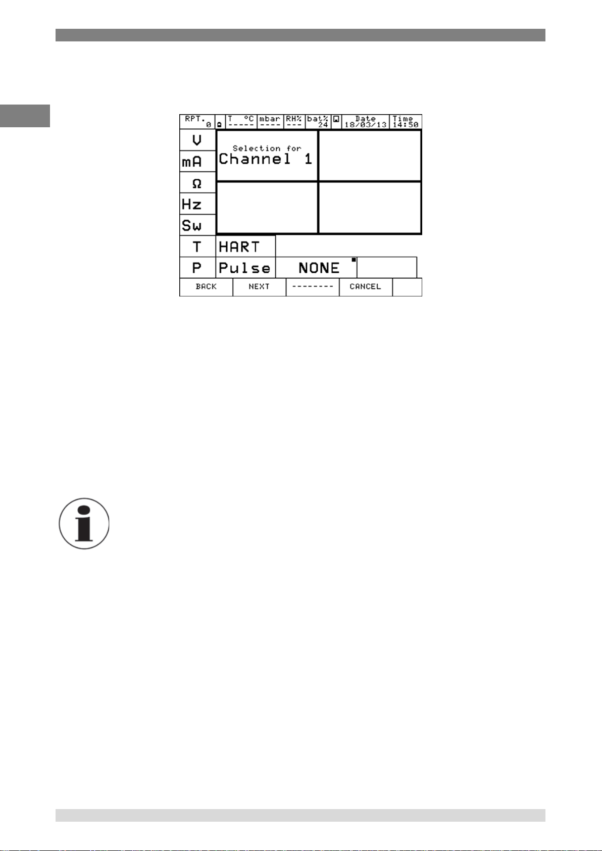
Automatically the program shows the following screen and remains in this position till the operator
select what type of parameter to associate to Channel 1.
Figure 16 – Parameter selection
The possible choices are:
■ V (Voltage)
■ mA (Current)
■ (Resistance)
■ Hz (Frequency)
■ Sw (Switch (Open/Closed))
■ T (Temperature)
■ P (Pressure)
■ HART (Hart communication) [Only when the module is fitted]
■ PULSE (Pulse)
■ NONE (No selection)
Previous set-up
A small black square in the top right side of the selection of the
Figure 16 – Parameter selection, NONE, shows the last configuration of the selected
channel. To maintain the same setting press NEXT.
32 WIKA Operating Instruction, Pascal 100 and Pascal 100/IS
Page 33

6 Commissioning, operation
GB
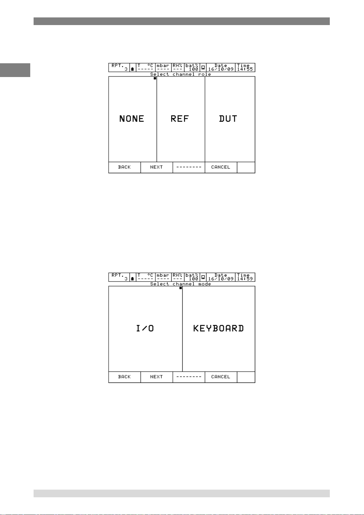
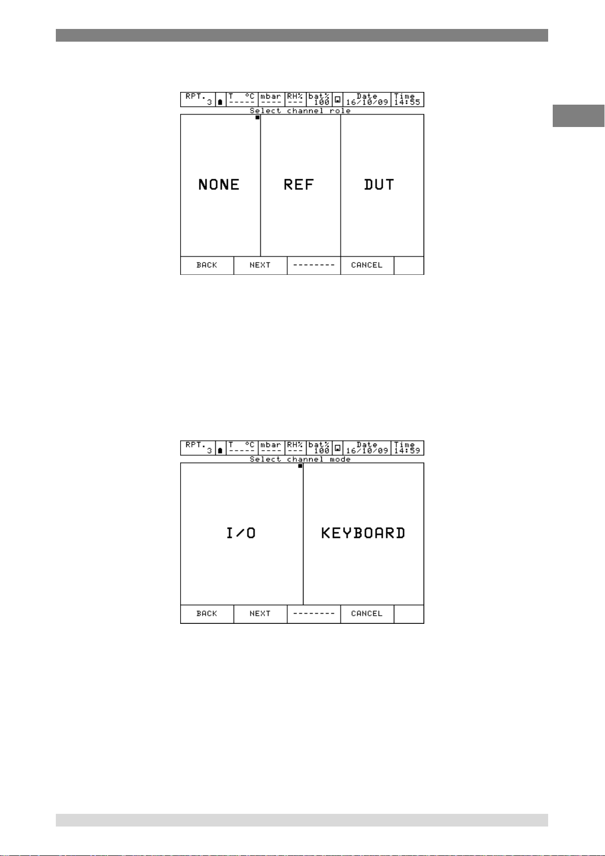
Once a particular parameter is selected, for example pressing “T” for temperature, the instrument
asks for the channel role:
Figure 17 – Channel role selection
NONE to use the channel for simple measurement
REF to use the channel as reference in a comparison calibration
DUT to use the channel as measurement of a Device Under Test in a comparison
calibration
Press one of the above button (NONE, REF, DUT) to define the channel role.
Pressing REF or DUT the procedure continues as shown below:
I/O to assign a particular I/O module to the software channel.
KEYBOARD to setup by keyboard a particular value read from an external instrument
(i.e. analogue gauge).
Figure 18 – Channel mode selection
WIKA Operating Instruction, Model Pascal 100 and Pascal 100/IS 33
Page 34
6 Commissioning, operation
GB
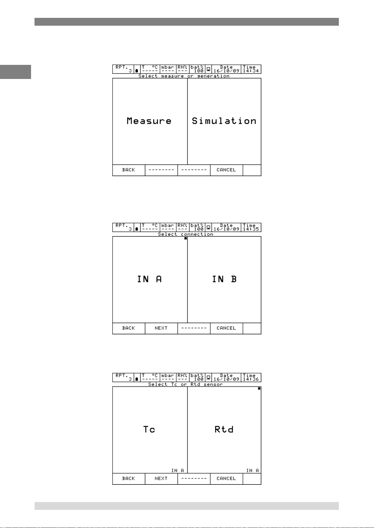
By selecting I/O the instrument requires now to specify whether to measure a signal or to perform a
simulation: for example Measure.
Figure 19 – Measure or Simulation selection
At this point the operator needs to select on which physical channel the thermoresistance has to be
connected, example IN A.
Figure 20 – Input module selection
It is necessary now to select a thermocouple (Tc) or a thermoresistance (Rtd):
Figure 21 – Tc / Rtd selection
34 WIKA Operating Instruction, Pascal 100 and Pascal 100/IS
Page 35

6 Commissioning, operation
GB
Selecting RTD the page for the thermoresistance set up is shown. Fourteen RTD’s types are
available, plus one RTD User (with coefficient defined by the user).
Figure 22 – Rtd type selection
Once the type of thermoresistance connected to the input IN A is identified, the operator must
indicate the measurement mode: 2 wires, 3 wires or 4 wires measurement; the engineering unit
(°C, °F, K) and related number of decimal.
Measurements of RTD - 4 wires
If possible it is recommended to perform RTD measurement with four wires to
eliminate parasite resistances of the connecting cables. All specifications for
thermoresistance aim for four wires measurement.
RTD USER must be selected when the operator needs to measure a non-standard RTD in
agreement with the following formula:
If T≥ 0 °C R(t)= Ro * (1 + A * t + B * T²)
If T< 0 °C R(t)= Ro * (1 + A * t + B * T² + C (t – 100) * t³)
Figure 23 – RTD parameters setup
WIKA Operating Instruction, Model Pascal 100 and Pascal 100/IS 35
Page 36

6 Commissioning, operation
GB
Once RTD USER is selected, it is possible to set the parameter of the RTD used.
A = X * 10-3 °C-1
B = X * 10ˉ7 °C-2
C = X * 10
-12
°C-3
Ro = Resistance @ t = 0,01 °C
X = Value
Next step is to define the measurement range. The range selection is necessary during the
calibration procedure to define the relationship between the REF and DUT channels.
Figure 24 – Range setup
Now it is possible to conclude the procedure by pressing the YES button or come back to the
previous step pressing NO.
Figure 25 – Channel setup confirmation
Once the YES key is pressed, the calibrator returns to the initial page where the user can proceed
with the measurement/simulation, or assign another function to a different software channel
following the same procedure.
36 WIKA Operating Instruction, Pascal 100 and Pascal 100/IS
Page 37

6 Commissioning, operation
GB
6.4.2 Other assignments
6.4.2.1 Pressure measurement
The following procedure illustrates the setting of Pascal 100 or Pascal 100/IS for pressure
measurement. The particular channel is selected by pressing one of the four big displays and then
pressing CHANNEL and ASSIGN from the menu, as shown below:
Figure 26 – Channel assign selection
Automatically the program shows the following screen and it remains in this position until the
operator points out what type of parameter he desires to associate to a selected channel, for
example to the Channel 1. In this case press P for pressure.
Figure 27 – Pressure parameter selection
The Pascal 100 or Pascal 100/IS can be equipped with up to two pressure modules and each of
them can handle up to three pressure sensors, two internals and one external with standard
accuracy.
WIKA Operating Instruction, Model Pascal 100 and Pascal 100/IS 37
Page 38

6 Commissioning, operation
GB
The instrument requires the channel role:
Figure 28 – Channel role selection
NONE to use the channel for simple measurement
REF to use the channel as reference in a comparison calibration
DUT to use the channel as measurement of a Device Under Test in a comparison
calibration
Press one of the above button (NONE, REF, DUT) to define the channel role.
Pressing REF or DUT the procedure continues as shown below:
I/O to assign a particular I/O module to the software channel.
KEYBOARD to setup by keyboard a particular value read from an external instrument
(i.e. analogue gauge).
Figure 29 – Channel mode selection
38 WIKA Operating Instruction, Pascal 100 and Pascal 100/IS
Page 39

6 Commissioning, operation
GB
Measure unit
bar
mbar
ftH2O@4°C
inH2O@4°C
inHg@0°C
psf
psi
atm
torr
mH2O@4°C
cmH2O@4°C
mmH2O@4°C
mHg@0°C
cmHg@0°C
mmHg@0°C
kg/m2@g_std
kg/cm2@g_std
MPa
kPa
hPa
Pa
By selecting I/O the procedure requires to select the type and the range of the sensor to be used.
The sensor is identified by the measurement range and the measurement mode (g = gauge
pressure or a = absolute pressure). This information is displayed under the writing PE-1 (first
external sensor) or PE-2 (second external sensor). See the the figure below as example:
Figure 30 – Pressure sensor selection
When the sensor has been selected, the next page helps to set the engineering unit and related
number of decimals.
Figure 31 – Pressure sensor parameters selection
The pressure engineering units available are:
WIKA Operating Instruction, Model Pascal 100 and Pascal 100/IS 39
Page 40

6 Commissioning, operation
GB
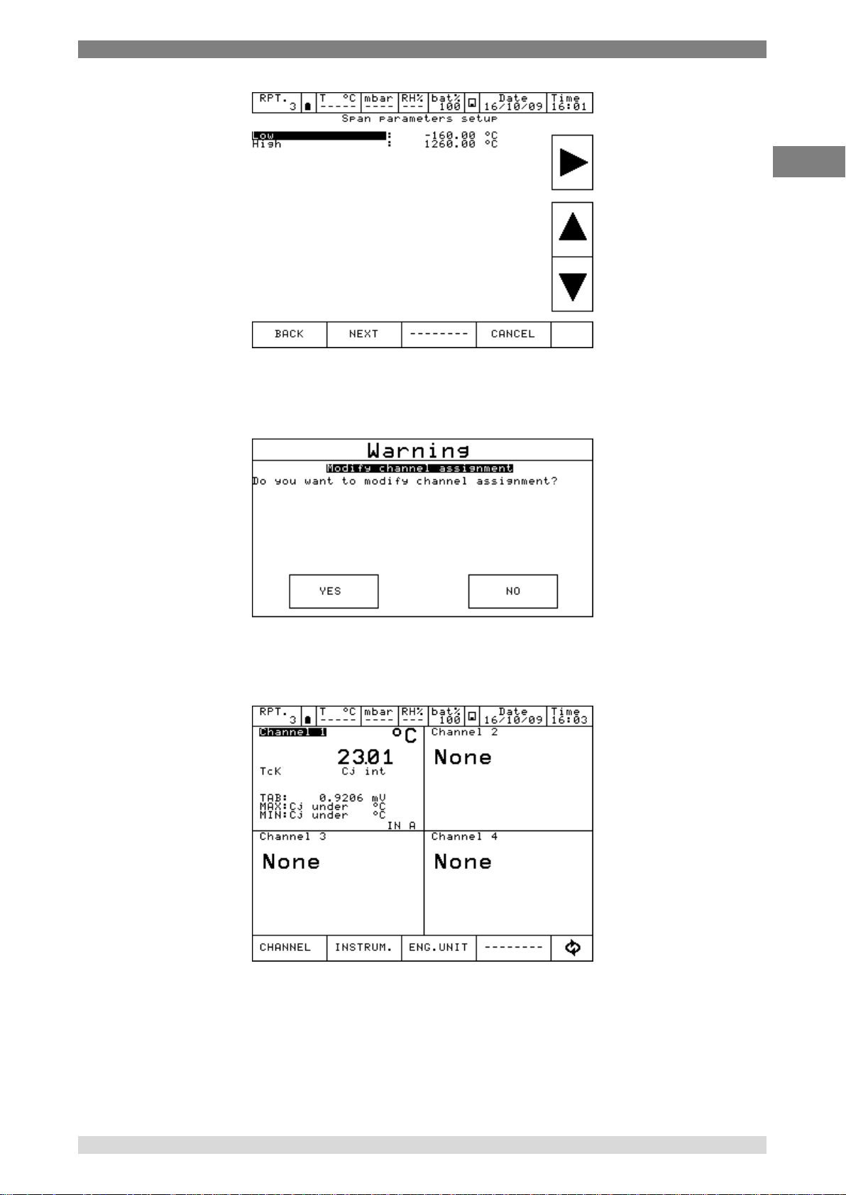
The next screen shows the Span parameter (measuring range). For default the sensor has its
maximum range equal to the measuring range (Span). If the Span has to be redefined, or to be
reduced, the same can be changed by using a numeric keyboard. The redefinition of the Span is
used during a calibration for comparison where a relationship between a REF and a DUT channel
has to be done.
Figure 32 – Sensor range setup
Now it is possible to finalize the procedure by pressing the YES button or come back to the
previous step pressing NO.
Figure 33 - Channel setup confirmation
Pressing the key YES, the channel is set up with the selected parameters and the screen with four
channels is displayed again.
Figure 34 – Main display with pressure measurement
40 WIKA Operating Instruction, Pascal 100 and Pascal 100/IS
Page 41

6 Commissioning, operation
GB
6.4.2.2 Thermocouple signal measurement
The following procedure shows the setup of Pascal 100 or Pascal 100/IS for temperature signal
measurement, for example, through a thermocouple connected to the input module. The channel
for measurement is selected by pressing one of the four large displays, once the menu CHANNEL
is selected, press ASSIGN as shown in the below figure.
Figure 35 – Channel assign selection
Automatically the program shows the following screen and it remains in this position until the
operator selects the type of parameter he desires to associate to the Channel 1.
Figure 36 – Temperature parameter selection
WIKA Operating Instruction, Model Pascal 100 and Pascal 100/IS 41
Page 42
6 Commissioning, operation
GB
Press T for Temperature.
The instrument requires the channel role:
Figure 37 – Channel role selection
NONE to use the channel for simple measurement
REF to use the channel as reference in a comparison calibration
DUT to use the channel as measurement of a Device Under Test in a comparison
calibration
Press one of the above button (NONE, REF, DUT) to define the channel role.
Pressing REF or DUT the procedure continues as shown below:
I/O to assign a particular I/O module to the software channel.
KEYBOARD to setup by keyboard a particular value read from an external instrument.
Figure 38 – Channel mode selection
42 WIKA Operating Instruction, Pascal 100 and Pascal 100/IS
Page 43

6 Commissioning, operation
GB
By selecting I/O the instrument requires now to specify whether to measure a signal or to perform a
simulation: for example Measure.
Figure 39 - Measure or Simulation selection
At this point the operator needs to select on which physical channel the thermocouple has to be
connected, example IN A.
Figure 40 - Input module selection
It is necessary now to select a thermocouple (Tc) or a thermoresistance (Rtd), for example Tc.
Figure 41 - Tc / Rtd selection
WIKA Operating Instruction, Model Pascal 100 and Pascal 100/IS 43
Page 44

6 Commissioning, operation
GB
Selecting Tc the page for thermocouple set up is shown as follow:
Figure 42 – Tc type selection
Next page helps the operator to select: the engineering unit (°C - °F - K) and the type of reference
cold junction (internal or external). Selecting “internal cold junction”, a Pt100 is directly connected
to the TC input pins, measures the environmental temperature; whereas by selecting “external cold
junction”, the temperature value must be inserted by using the keyboard.
Figure 43 – Tc parameters selection
The next screen shows the Span parameter (measuring range). In the default settings, the sensor
has its maximum range equal to the measuring range (Span). If the Span has to be redefined, or to
be reduced, same can be changed by using a numeric keyboard. The redefinition of the Span is
used during a calibration for comparison where a relationship between a REF and a DUT channel
has to be done.
44 WIKA Operating Instruction, Pascal 100 and Pascal 100/IS
Page 45
6 Commissioning, operation
GB
Figure 44 – Tc range selection
Now it is possible to finalize the procedure by pressing the YES button or come back to the
previous step pressing NO.
Figure 45 - Channel setup confirmation
Pressing the key YES, the channel is set up with selected parameters and the screen with four
channels is displayed again.
Figure 46 - Main display with temperature measurement
WIKA Operating Instruction, Model Pascal 100 and Pascal 100/IS 45
Page 46

6 Commissioning, operation
GB
6.4.2.3 Electrical parameter measurement
The following procedure shows the settings of Pascal 100 or Pascal 100/IS for the electrical
parameters measurement through the input module. To select the channel press on one of the four
large displays, then press CHANNEL: once menu is displayed press ASSIGN. Procedure is shown
below:
Figure 47 - Channel assign selection
Automatically the program shows the following configuration and it remains in this position till the
operator selects the parameter to be associated to the Channel 1.
For example, press mA for current measurement.
Figure 48 – mA parameter selection
46 WIKA Operating Instruction, Pascal 100 and Pascal 100/IS
Page 47
6 Commissioning, operation
GB
The instrument requires the selection of the role:
Figure 49 - Channel role selection
NONE to use the channel for simple measurement
REF to use the channel as reference in a comparison calibration
DUT to use the channel as measurement of a Device Under Test in a comparison
calibration
Press one of the above button (NONE, REF, DUT) to define the channel role.
Pressing REF or DUT the procedure continues as shown below:
I/O to assign a particular I/O module to the software channel.
KEYBOARD to setup by keyboard a particular value read from an external device.
Figure 50 - Channel mode selection
Then press I/O to assign a particular I/O module to the software channel, or press keyboard to
setup a particular value read from an external device.
WIKA Operating Instruction, Model Pascal 100 and Pascal 100/IS 47
Page 48
6 Commissioning, operation
GB
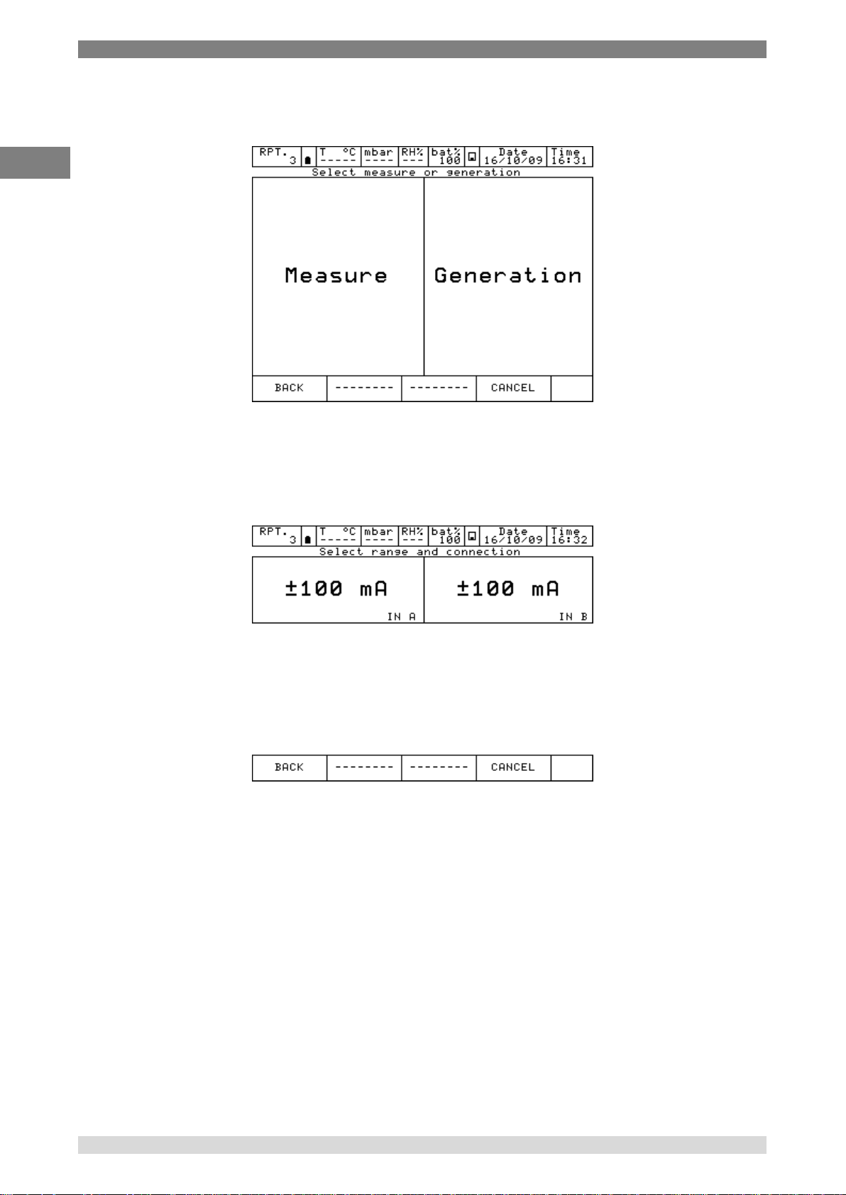
By selecting the input/output (I/O) the procedure requires to select MEASURE (to measure a
signal) or GENERATION (to generate a signal)
Figure 51 – Measure or generation selection
By pressing MEASURE, automatically the Pascal 100 or Pascal 100/IS requires to select input
module (IN A- IN B) to be used. Double input will be displayed when the calibrator has a double
input configuration and both modules are not assigned yet. Otherwise only one input will be
displayed
Figure 52 – mA selection from IN A or IN B
48 WIKA Operating Instruction, Pascal 100 and Pascal 100/IS
Page 49

6 Commissioning, operation
GB
The next step shows the span parameter (measuring range). In the default settings, the maximum
range is equal to the measuring range (span). If the span has to be redefined or reduced, it can be
changed by using a numeric keyboard. To access to the keyboard use the arrows displayed on the
right side of the screen. Change of the span is used during a calibration for comparison where a
relationship between a REF and a DUT channel has to be assigned.
Figure 53 – mA range setup
Now it is possible to finalize the procedure pressing YES or come back to the previous step
pressing NO.
Figure 54 - Channel setup confirmation
Pressing YES, the channel is assigned to the selected parameter and the screen with four
channels is displayed again.
Figure 55 – Main display with mA measurement
WIKA Operating Instruction, Model Pascal 100 and Pascal 100/IS 49
Page 50
6 Commissioning, operation
GB
6.4.2.4 Temperature Simulation
The procedure for the temperature simulation assignment is similar to the measurement one as
described previously, except for the step “Select measure or simulation” where the operator needs
to press SIMULATION instead of MEASURE. In the following step the user needs to select one of
the output OUT A or OUT B available.
Figure 56 – Generation module selection
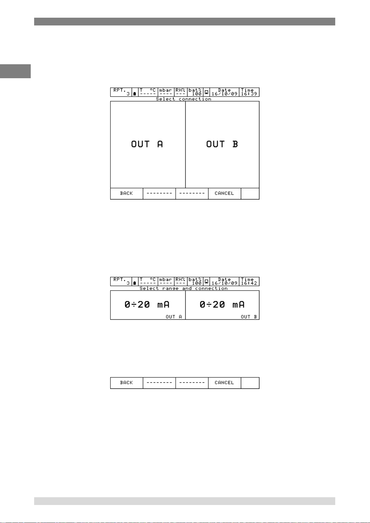
6.4.2.5 Electrical parameter generation
The procedure for the assignment of the generation of an electric parameter (for example mA) is
similar to the electrical signal measurement one as described previously, except for the step
"Select measure or generation” where the operator needs to select GENERATION instead of
MEASURE.
Then the user needs to select OUT A or OUT B (if available).
Figure 57 – mA generation module selection
50 WIKA Operating Instruction, Pascal 100 and Pascal 100/IS
Page 51

6 Commissioning, operation
GB
The next selection ask if a passive or active loop is required (with 24 V supply for the loop).
Figure 58 – mA loop generation setup
6.4.2.6 Channel 4 – mathematic functions
Channel four has an additional setting named CALC. This function enables to display on channel
n. 4 a value, result of the combination of the values displayed in channel 1 and 2. To access, press
on the display of channel 4, then Channel on the bottom bar and then assign.
Figure 59 – Channel 4 assignment
WIKA Operating Instruction, Model Pascal 100 and Pascal 100/IS 51
Page 52

6 Commissioning, operation
GB
Pressing CALC the followings are displayed:
Figure 60 – Calculation types
CH1 + CH2 channel 4 displays the total value of the values displayed on channel 1 and 2
CH1 - CH2 channel 4 displays the difference value of the values displayed on channel 1 and 2
Cell Load channel 4 displays the ratio mV/V of the load cells
CH1+CH2 and CH1-CH2 functions can be used only if channel 1 and 2 are set with the same
values: same engineering unit, same number of digits, no channel assigned with error indication.
In this case, below what will be displayed:
Figure 61 - Calculation on Channel 4
52 WIKA Operating Instruction, Pascal 100 and Pascal 100/IS
Page 53

6 Commissioning, operation
GB
Otherwise the channel 4 will be displayed as:
Figure 62 – Calculation not possible on Channel 4
For the Cell Load, the channel 4 can calculate the result coming from a load cell connected as per
the below scheme:
Figure 63 – Cell Load connection
WIKA Operating Instruction, Model Pascal 100 and Pascal 100/IS 53
Page 54

6 Commissioning, operation
GB
Calculation is possible only when channel 1 is assigned for mV measurement (bridge signal) and
channel 2 is assigned for V generation, range 0÷20 V (bridge supply). Moreover channel 1 should
not be set in error mode.
In this case, below what will be displayed:
Figure 64 – Cell Load calculation
Pascal 100 or Pascal 100/IS allows to manage the sensitivity of the load cell from 0 mV/V up to
9.99999 mV/V.
Moreover, on channel 4, the SCALING function can be assigned through the menu CHANNEL in
order to display an engineering unit more appropriate (for example Kg or a pressure unit).
Figure 65 – Cell Load calculation with Scaling function active
54 WIKA Operating Instruction, Pascal 100 and Pascal 100/IS
Page 55

6 Commissioning, operation
GB
6.4.2.7 HART channel assignment
To select the channel press on one of the four large displays, then press CHANNEL. Once menu is
displayed press ASSIGN. Procedure is shown below:
Automatically the program shows the following configuration and it remains in this position till the
operator selects the parameter to be associated to the Channel 1.
For example, press HART for HART measurement.
The instrument requires the selection of the role:
WIKA Operating Instruction, Model Pascal 100 and Pascal 100/IS 55
Page 56
6 Commissioning, operation
GB
NONE to use the channel for simple measurement
REF to use the channel as reference in a comparison calibration
DUT to use the channel as measurement of a Device Under Test in a comparison calibration
Press one of the above button (NONE, REF, DUT) to define the channel role.
Pressing REF or NONE the procedure continues as shown below:
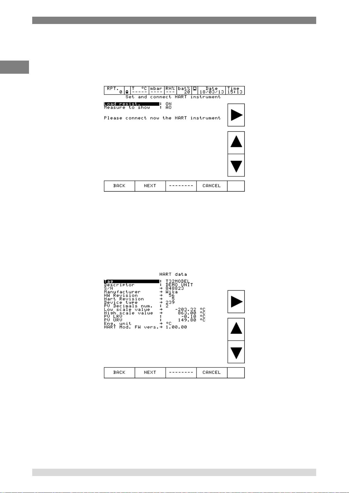
Here the user can choose if enable the internal module 250Ω resistor (ON or OFF), and choose
what digital measure wants to show as the big value displayed on the channel window: PV or AO.
The other type of measure however is displayed on the channel in a smaller font.
Before pressing NEXT be sure to already make the proper connections to the HART instrument as
show in previous chapter
Press NEXT and, after few seconds, if no error is shown the following appear (depending on HART
transmitter type connected):
Here the user has the possibility to change some parameter (they showed with ‘:’ moving the black
line with arrows.
They can be: TAG, DESCRIPTOR, PV decimals units, PV LRV and PV URV.
56 WIKA Operating Instruction, Pascal 100 and Pascal 100/IS
Page 57

6 Commissioning, operation
GB
After positioned to the parameter needed to modify press right arrow key, for example on the TAG
parameter:
If desired delete all the characters with backspace and insert the desired. After press ENTER to
store the parameter inside the HART transmitter; the Pascal will return to the previous display.
IMPORTANT NOTE: HART requires that all the characters must be in upper case in order to
be properly stored.
Press NEXT to continue.
The next step shows the span parameter (measuring range). In the default settings, the maximum
range is equal to the measuring range (span). If the span has to be redefined or reduced, it can be
changed by using a numeric keyboard. To access to the keyboard use the arrows displayed on the
right side of the screen. Change of the span is used during a calibration for comparison where a
relationship between a REF and a DUT channel has to be assigned.
Now it is possible to finalize the procedure pressing YES or come back to the previous step
pressing NO.
WIKA Operating Instruction, Model Pascal 100 and Pascal 100/IS 57
Page 58

6 Commissioning, operation
GB
Pressing YES, the channel is assigned to the selected parameter and the screen with four
channels is displayed again.
6.4.2.8 HART trimmer calibration
When the HART transmitter needs to be recalibrated or adjusted the HART menu can achieve
these two types of possibilities:
- ADJ.SCL
- CAL.TRIM
CAL.TRIM permits to correct the analog mA generation, of the HART transmitter, referred to the
digital AO value displayed if the output DAC goes out of tolerance.
Zero and Span needs to be corrected.
If the user wants to recalibrate the Trim. an INPUT mA measurement channel has to configured as
REF channel. In addition, the loop wiring needs to flow to the IN mA terminals.
If no REF mA Input channel is configured first an error will be shown.
58 WIKA Operating Instruction, Pascal 100 and Pascal 100/IS
Page 59

6 Commissioning, operation
GB
The instrument shows:
Press “Zero Trim” or “Span Trim”, and the display shows (in this case Span Trim is selected):
The HART instrument is put in fixed mode generation (4 or 20 mA) and the REF channel is
measuring the true analog mA generation. To re-align to the correct 20 mA (or 4 mA) generation
press “Calibrate” button.
If needed follow the same procedure for “Zero Trim”.
WIKA Operating Instruction, Model Pascal 100 and Pascal 100/IS 59
Page 60
6 Commissioning, operation
GB
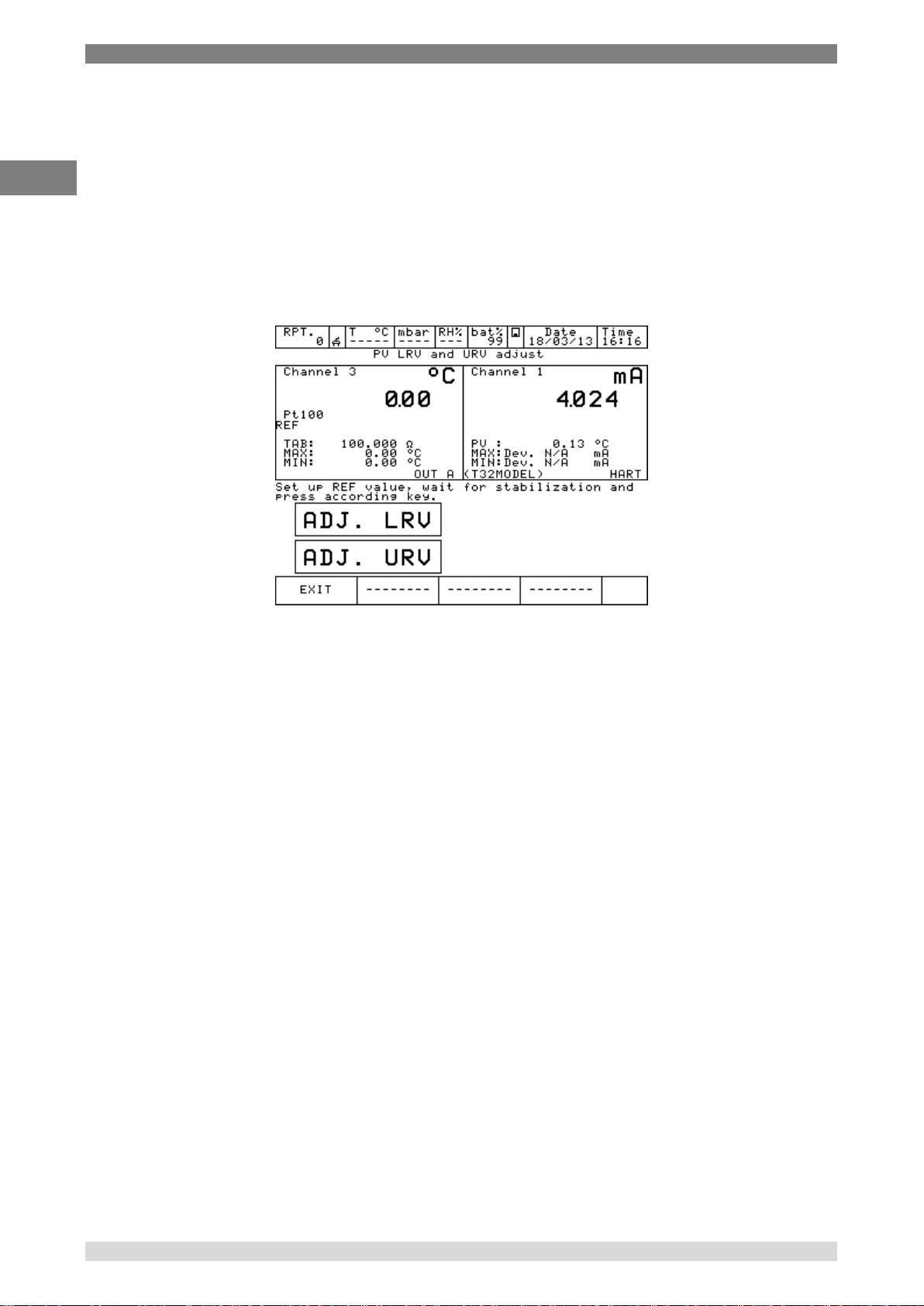
6.4.2.9 HART scale adjust
ADJ.SCL permits to align the range of PV to the Lower and Upper mA generation values.
The Lower value of PV is the value at which the transmitter will generate the 4 mA nominal value,
and the Upper value is the value at which the transmitter will generate the 20 mA nominal value.
Here is described the “automated” procedure that permits to align in “real-time” these values. The
user can also change them manually in the “HART data” page as seen before.
If the user wants to adjust the scale a channel of the same input type of the transmitter has to be
configured as REF channel. If no REF channel is configured first an error will be shown.
Press ADJ.SCL menu and the following is shown (assuming that we are using a Pt100 transmitter,
e REF simulation Pt100 channel is configured as Channel 3):
Set the REF Channel to the desired value that permits to output by the transmitter the 4mA value
(example 0°C). When the value is stable press ADJ. LRV button.
Now set the REF Channel to the desired value that permits to output the transmitter the 20mA
value (example 150°C). When the value is stable press ADJ. URV button.
Now the transmitter will generate 4 and 20 mA between 0 °C – 150 °C.
60 WIKA Operating Instruction, Pascal 100 and Pascal 100/IS
Page 61
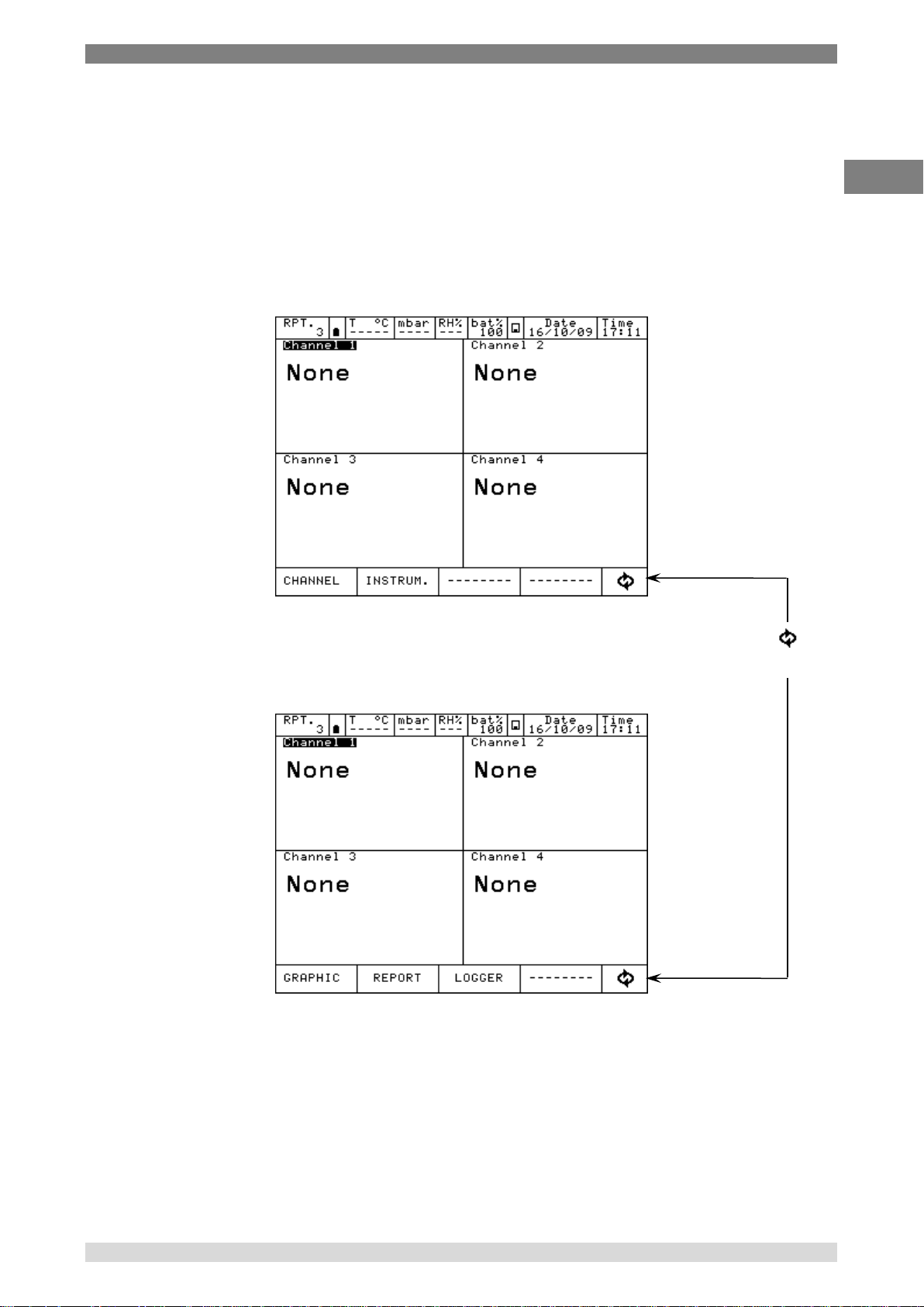
6 Commissioning, operation
GB
Pressing the key , the menu
change as in figure below
6.5 Menu
The MENU is available in the bottom of the display and changes according to the step of the
procedure that is running on the instrument.
The MENU sections can be selected pressing on their screen portion respectively.
Pressing it, a menu will be displayed on the left side of the display, showing all the possible options
available in that moment for that specific configuration.
For example, to change the channel configuration, first select the channel pressing one of the 4
displays, then select Channel from the MENU and then ASSIGN.
To modify the number of DECIMALS to be displayed, select the box INC.DEC o DEC.DEC to
increment or decrement the decimals.
WIKA Operating Instruction, Model Pascal 100 and Pascal 100/IS 61
Page 62

6 Commissioning, operation
GB
6.5.1 Channel Menu
Inside the bottom line menu, the box CHANNEL allows to change and assign the selected channel:
this section is dynamic and changes according to the procedure followed
Figure 66 – Channel menu showing
For example, channel has been assigned for V measurement: pressing the CHANNEL box, the
following menu will be displayed:
Figure 67 – Channel menu showing for electrical input
The menu consists of:
STATUS to visualize the channel configuration and the measure range
RES.MXMN to reset max and min value of the range
SCALING to scale a signal and display it with a different engeneering unit
FILTER to filter the signal
HOLD. ON to hold the last display
OFFSET. ON to set the zero for the measurement
ASSIGN. to assign the channel
In case an electrical parameter is simulated, the box CHG.OUT will be displayed in the menu: this
key enables the access to a keyboard to set up the values to be generated.
62 WIKA Operating Instruction, Pascal 100 and Pascal 100/IS
Page 63

6 Commissioning, operation
GB
The CHANNEL menu for the electrical, temperature and pressure signals is shown here below :
Figure 68 – Channel menu showing for pressure
INC.DEC o DEC.DEC boxes are displayed: they enable to modify the number of DECIMALS to be
displayed.
More Information about the Channel Menu is available in chapter 6.6
6.5.2 Instrument Menu
This menu enables to see and change the settings of the instrument.
Pressing on INSTRUM the following menu is displayed.
Figure 69 – Instrument menu showing
WIKA Operating Instruction, Model Pascal 100 and Pascal 100/IS 63
Page 64

6 Commissioning, operation
GB
1) SETUP to set up the instrument configuration, as per below picture:
Figure 70 – Instrument setup screen showing
Different languages are available: 2 different ones are available on each instrument configuration.
Standard languages are English and Italian.
Serial Baud rate must be set up at 115200 to enable data transfer to the PC.
2) LOCK SCR To lock and unlock the screen. To unlock press LAMP
(text 5 of the keyboard)
3) STATUS to see the status of the calibrator:
Model – Serial Number – Version – Languages – Build date – I/O Modules
installed – Date – Time – Battery voltage
Figure 71 – Instrument status page showing
64 WIKA Operating Instruction, Pascal 100 and Pascal 100/IS
Page 65

6 Commissioning, operation
GB
4) 2 CH To show 2 channels on the dispaly, as per picture below.
Figure 72 – Two channels display
5) 4 CH To visualize all the 4 Channels on the display.
6) 24V OUT To power on /off the 24 Vcc to supply the power to the device under test
6.5.3 Report Menu
This menu enables to access to the calibration reports and calibration procedures section.
For more information please refer to Chapter 6.7
6.5.4 Engineering unit Menu
Engineering unit displayed can be changed faster selecting and pressing the box ENG.UNIT on the
active menu: this is possible only for channels assigned for pressure or temperature
measurements.
6.5.5 Logger Menu
Selecting the box LOGGER the following menu is accessed: SETUP, VIEW. LOG, DEL.LOGS
For more information please refer to Chapter 6.8.
6.5.6 Calibration Menu
The calibration menu allows the calibration of the parameters available on the calibrator.
Separate Operating instruction available.
WIKA Operating Instruction, Model Pascal 100 and Pascal 100/IS 65
Page 66

6 Commissioning, operation
GB
6.5.7 Graph Menu
To display the behavior of a variable associated to a channel in a certain range of time, press
GRAPHIC inside the active menu. The box SETUP is displayed in the new menu, enabling the
selection of the following parameters:
Sampling time (hh, mm, ss)
Scale (automatic, manual)
Lower limit (in manual)
Upper limit (in manual)
X Axis (fixed or tracked to cursor)
Select the values with the arrows and then press START. The graphic will be visualized on the
display, as per the figure
Figure 73 – Realtime graph
Through the box CURS. the cursor can be moved, visualizing for every step the value of the
graphic. Pressing INFO OFF all the displayed information will be hidden, while with GRID OFF the
grid will be hidden. Both the information and the grid can be displayed again pushing the related
buttons.
Through the box (circle with arrows) in the bottom right side of the menu, it’s possible to
acces to all other menu not shown on this screen.
66 WIKA Operating Instruction, Pascal 100 and Pascal 100/IS
Page 67
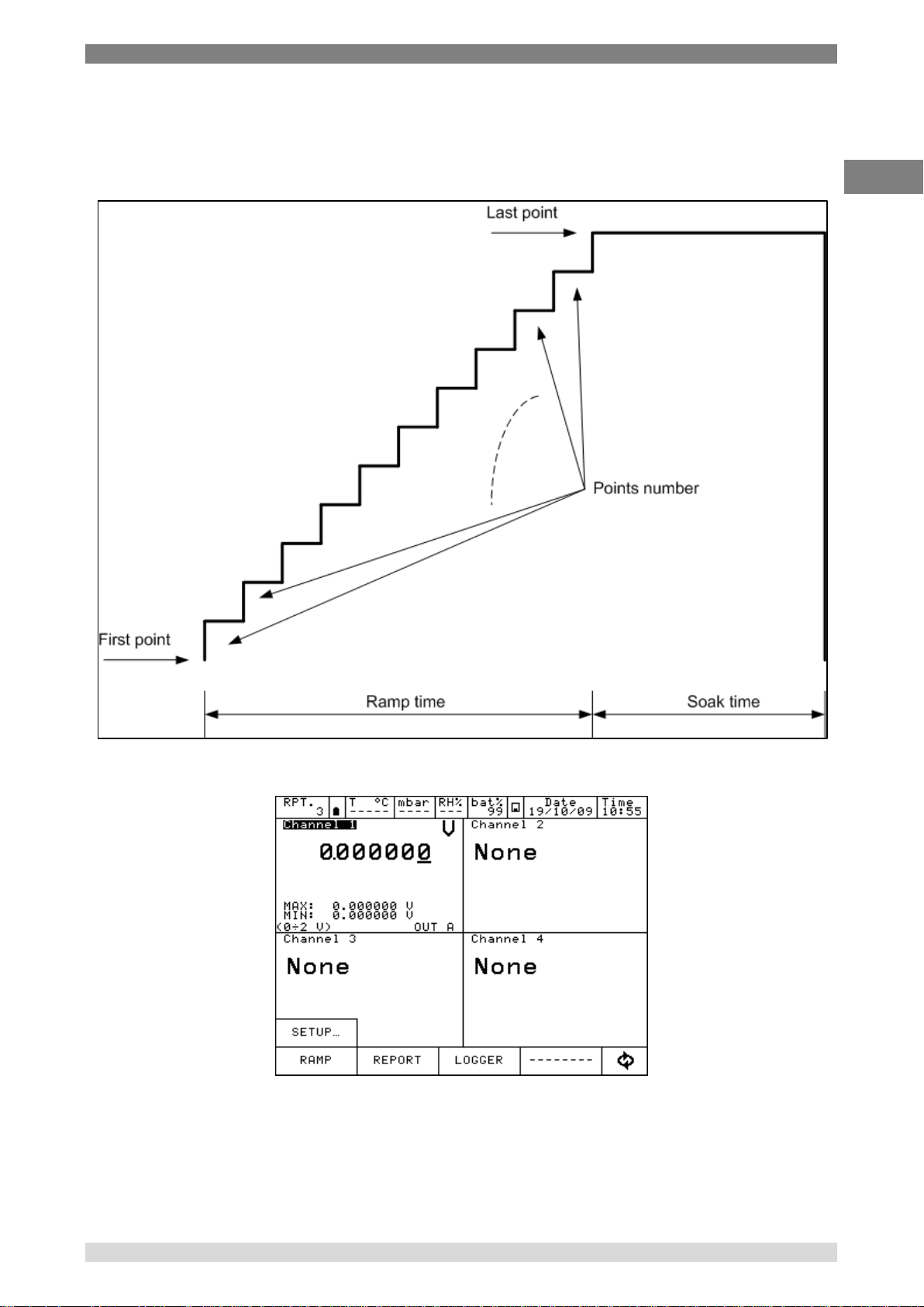
6 Commissioning, operation
GB
6.5.8 Ramp Menu
This menu is displayed when the parameter are associated to an ouput card.
This function allows to set a ramp that automatically shift the generated value in configurable
steps. If both generation outputs are available, each one associated to a channel, two ramps can
be set up and can be run simultaneously. Ramp can be programmed as per below:
Press RAMP:
Figure 74 – Ramp profile
Figure 75 – RAMP Menu
WIKA Operating Instruction, Model Pascal 100 and Pascal 100/IS 67
Page 68
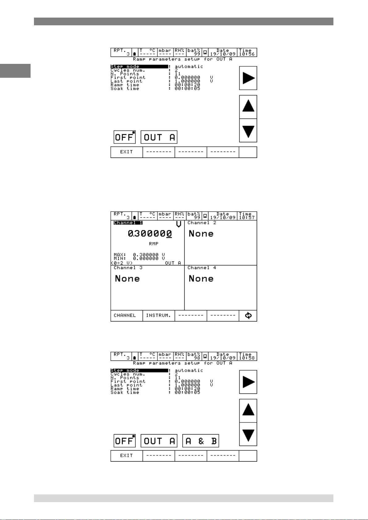
6 Commissioning, operation
GB
Press SETUP to set the ramp:
Figure 76 – Ramp parameters setup
Here above a ramp has been set: starting from 0 V, in 11 steps it reaches 1 V after 20 sec.: then it
remains standstill for 5 sec. The ramp will be executed 2 times (Cycles num.).
Press OUT A to start the ramp function: the instrument will show the main screen and the writing
RMP will be displayed to show that the function ramp is active.
Figure 77 - Ramp running
If another channel is assigned to OUT B, here below you can see how the Ramp will be shown:
Figure 78 – Ramp setup with both OUTs
OUT A & B are both available. The Ramp can start for both the channels simultaneously
68 WIKA Operating Instruction, Pascal 100 and Pascal 100/IS
Page 69

6 Commissioning, operation
GB
6.5.9 Disk Menu
Data related to the Reports, Loggings and Calibration procedures are stored as files into the
internal memory of the equipment.
Press Menu DISK, and the following options will be displayed:
Figure 79 – DISK Menu
FORMAT allow to cancel completely the virtual DISK. This operation will cancel all the store
data. Before proceeding the instrument will ask a final confirmation to the operator.
DEFRAG this operation may be required when many data are created and deleted
continuously. Inside the internal memory of the Disk, in fact, empty spaces could
be generated: this may lead to a warning message related to the shortage of the
memory and the impossibility to store new data. To recover this space, please
proceed with the Defrag: the existing data will not be lost but a certain time is
required to complete the procedure.
6.6 Measurement Channel
When a measure is displayed, the ENG.UNT will appear.
Figure 80 – Main screen
WIKA Operating Instruction, Model Pascal 100 and Pascal 100/IS 69
Page 70

6 Commissioning, operation
GB
6.6.1 Status
Press CHANNEL and then press STATUS to visualize all the parameters related to the status of
the channel (1, 2, 3, and 4): the configuration of each channel is displayed. Press the arrows in the
bottom menu to change the channel. See the below picture:
Figure 81 – Channel status page
Press EXIT to return to the initial screen.
6.6.2 Res. MxMn
Press Res. MxMn to restart the Max and Min value displayed on the channel.
6.6.3 Scaling
The SCALING enables to display the value into a different engineering unit. Press SCALING and
access to the below window:
Low Scl: min. value of the signal and reading scale (e. g. 0 kg at 0 bar)
High Scl: max. value of the signal and reading scale (e. g. 10 kg at 1 bar)
Eng. unit Scl: new engineering unit desired
Decimals num.: Number of decimals required
Transfer. funct.: linear, square root, quadratic
Figure 82 – Scaling parameters setup
70 WIKA Operating Instruction, Pascal 100 and Pascal 100/IS
Page 71
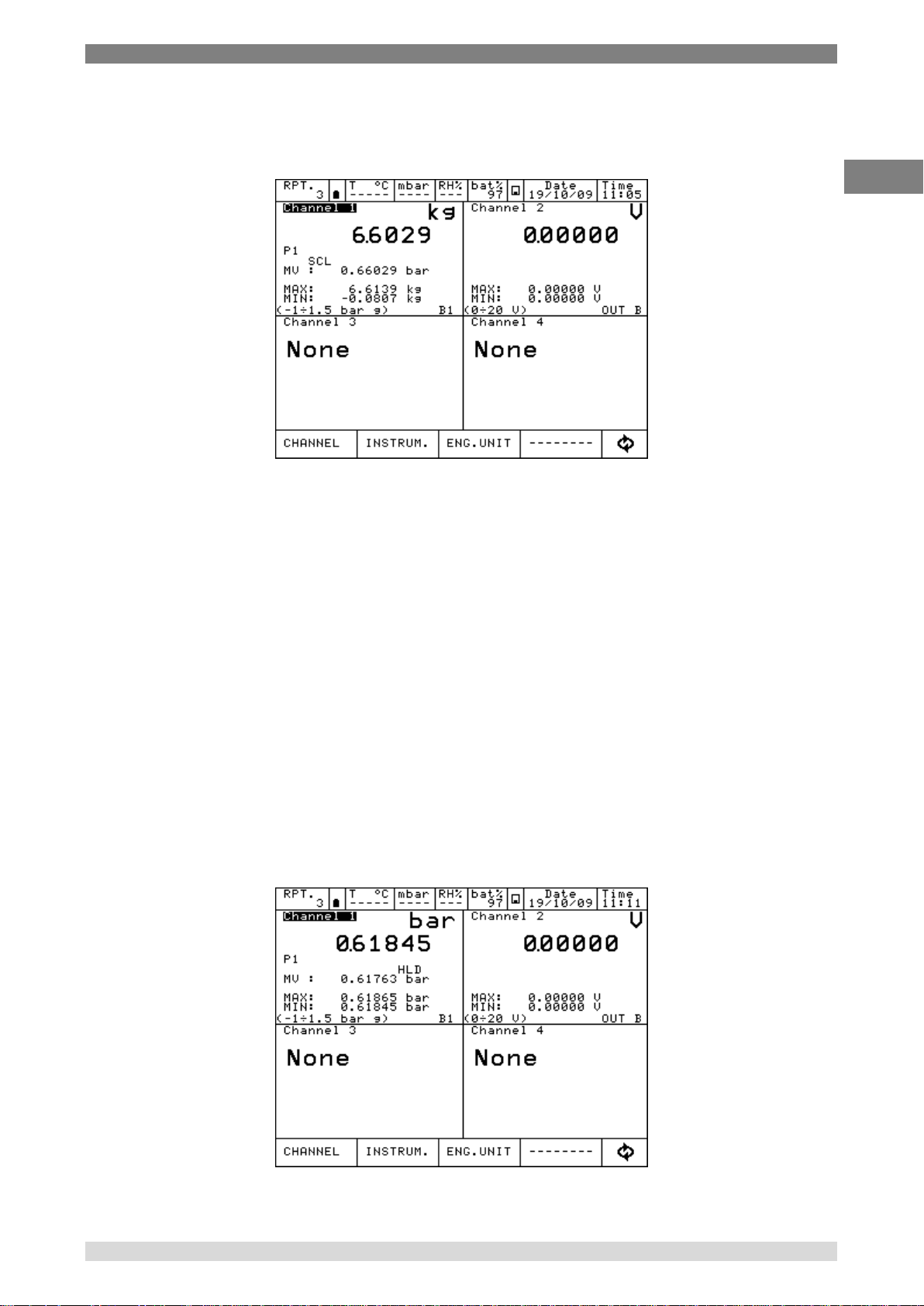
6 Commissioning, operation
GB
Once all parameters are set, press ON to enable the function: on the main display SCL writing will
appear. The new value will be displayed with the new engeneering unit in big letters. The existing
measurement will be displayed below in small letters. Example available here below:
Figure 83 – Channel with Scaling enabled
6.6.4 Filter
The FILTER can filter a measurement.
Press FILTER to visualize: “Filter parameter setting”
Filter can be set through the following:
Filter weight: in percentage
Select the filter weight and then press ON.
FLT writing will be displayed when filter is active. Filtered value will be displayed in big letters, real
value will be displayed below in small letters.
6.6.5 Hold On – Hold Off
HOLD ON-HOLD OFF is used to freeze what displayed in a specific channel.
Press HOLD ON to hold the values: HOLD OFF will appear. Press it to unlock the channel. HOLD
ON will appear again
HLD on the display means that the values are hold. See below:
Figure 84 – Channel with HOLD enabled
WIKA Operating Instruction, Model Pascal 100 and Pascal 100/IS 71
Page 72
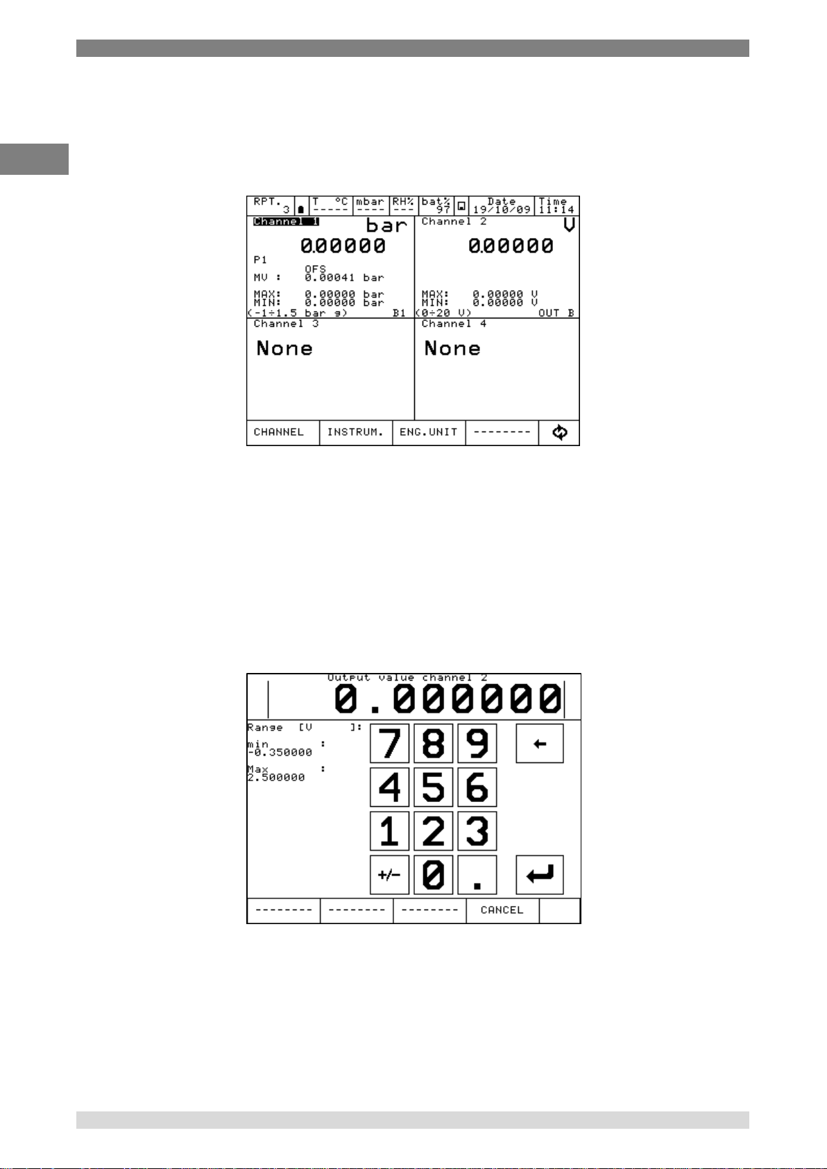
6 Commissioning, operation
GB
6.6.6 Offset On – Offset Off
OFFSET ON – OFFSET OFF is used to restar the measurement on a specific channel
Press OFFSET ON to restart: zero will be displayed and OFFSET OFF will appear. Press to come
back to the previous value.
OFS indicates that the OFFSET is ON.
Figure 85 – Channel with OFFSET enabled
6.6.7 Inc. Dec – Dec. Dec
If channel is set up for pressure or temperature measurements in the CHANNEL menu the
functions INC.DEC. e DEC.DEC. are displayed. These functions allow to increment/decrement the
number of the displayed digits
6.6.8 Chg. Out
CHG.OUT allows to change a signal coming out from an Output card.
Press CHG. OUT to display a keyboard to select the value of the signals within the limits specified
during the assignment (clarly indicated under “min” e “Max” on the left side).
Figure 86 – Generation / simulation value modifing
72 WIKA Operating Instruction, Pascal 100 and Pascal 100/IS
Page 73

6 Commissioning, operation
GB
Press here, a small
black square is shown
The keyboard can be accessed pressing on the right side of the displayed value as shown below:
Figure 87 – Generation value – how to modify
Press to visualize at the bottom menu the 4 arrows as per the below image:
Figure 88 – Generation value – how to modify
Cursor can be moved right and left using the first 2 arrows starting from the left side. The selected
cell value can be increased or decreased using the remaining 2 arrows on the right side.
WIKA Operating Instruction, Model Pascal 100 and Pascal 100/IS 73
Page 74

6 Commissioning, operation
GB
6.7 Report
To create a report one channel has to be set as REF (Reference) and another one as DUT (Device
Under Test): reference signal and direct measurement (or manual input by keyboard) are required.
For the REFERENCE: remember to set the range equivalent to the one of the DUT. When the
channel is assigned as reference, the symbol REF will appear.
For the DUT: remember to define the max error and the declaration. A bargraph will be displayed
on the DUT channel. When the channel is device under test, the symbol DUT will appear.
Press REPORT, the below menu is displayed:
VIEW RPT View Reports
SETUPRPT Set up Reports
DEL.RPTS deletes all the Reports
VIEW PRC View Procedures
SETUPPRC Set up Procedures
DEL.PRCS Delete all the Procedures
Figure 89 – Report menu
Press SETUPRPT to create a new Report.
Info required are:
Report name
DUT model (Device Under Test)
DUT Serial Number (Device Under Test)
Operator
Job Number
Found Left
Up Down
N. Points
74 WIKA Operating Instruction, Pascal 100 and Pascal 100/IS
Page 75

6 Commissioning, operation
GB
A standard Report configuration for the calibration of a pressure trasmitter 0-1 bar range is
available here below
Figure 90 – Report setup
Once completed Press STORE per memorize the data.
The following screen will appear:
Figure 91 – Store Report request
Press YES to store the report set up and then press again yes to run the report.
Figure 92 – Report run request
WIKA Operating Instruction, Model Pascal 100 and Pascal 100/IS 75
Page 76
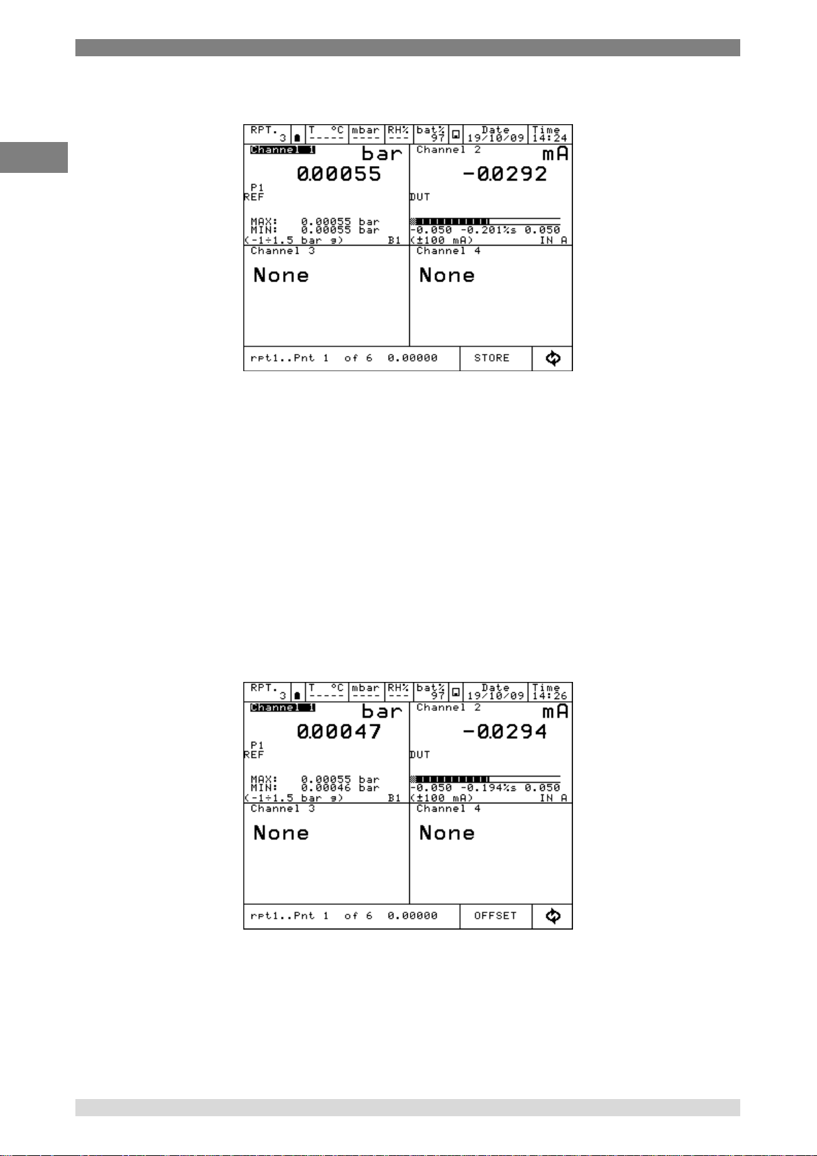
6 Commissioning, operation
GB
The main screen will be displayed as per below:
Figure 93 – Report running display
On the bottom menu, the report name (rpt1), the calibration point (1of 6) and the related reference
value (0.00000) will be shown. Press STORE to store the first calibration point: the switch to the
second point is done automatically (pnt 2 will be shown), and so on for all the predefined
calibration points. Pay attention to the bargraph in the DUT display: check if point is inside or
outside the limit specified during the DUT assignment.
Once the calibration cycle is defined, the generation of an electrical signal is done automatically.
For the pressure, instead, the operator has to reach the required pressure values using the manual
pump and the fine adjustment.
During the configuration process the operator can name the report: the same can be recalled when
the same procedure is required.
In any moment the operator can stop the calibration pressing ABORT.
To make the zero on the reference channel REF, press OFFSET before storing the first calibration
point: this function is displayed as OFS on the channel display, under the measurement value.
Press again OFFSET to come back to the original configuration: OFS will disappear.
Figure 94 – Report running display – next menu
Once the last calibration point is done, press STORE (or ABORT): the Report will end
automatically and the display will go back to its original configuration.
76 WIKA Operating Instruction, Pascal 100 and Pascal 100/IS
Page 77

6 Commissioning, operation
GB
Right arrow
Up & Down
arrows
To visualize the report, access to REPORT menu and press VIEW RPT to view the stored reports:
Figure 95 – Display Report list
The above picture shows the list of the existing report: name and status are displayed.
Under the status, the writing AS FOUND is displayed when the calibration data refers to a
calibration process done on an instrument without any adjustment: when a date is available this
means that calibration process is complete (AS FOUND AS LEFT). If the report has never been
run, VOID will be displayed next to the name.
Press the arrows to move the cursor up and down to select the report, press on the right arrow to
visualize the information available in the report.
The menu DELETE allows to cancel the reports: a confirmation is required by the operator before
proceeding
Selecting the name of the REPORT, the SETUP of the report will be displayed:
WIKA Operating Instruction, Model Pascal 100 and Pascal 100/IS 77
Figure 96 – Display Report setup
Page 78

6 Commissioning, operation
GB
Scrolling menu
Pressing POINTS, the list of the calibration points will be shown:
Figure 97 – Display test points Report
Pressing RESULT, the calibration results are shown:
Figure 98 – Display Report results
Press the “scrolling menu”, menu with “As found”, “As left”, “Up”, “Down”, will appear to enable to
see the calibration results related to the different calibration stages.
“As found”, (calibration points before any adjustment on the DUT) “As left” (calibration points after
the adjustment on the DUT has been carried out),“Up” (calibration points going up), “Down”
(calibration points going down).
Pressing GRAPHIC, the graphic of the calibration will be displayed, see below:
78 WIKA Operating Instruction, Pascal 100 and Pascal 100/IS
Figure 99 – Display Report in graphic mode
Page 79

6 Commissioning, operation
GB
X axis represents the calibration points related to the reference (REF).
Y axis represents the error in percentage (compared to the Reading range, as assigned to the
DUT) related to the Device Under Test channel (DUT).
From REPORT menu, select DEL.RPTS to cancel all the reports in the memory.
6.8 Data Logger
The LOGGER function allows to store the data displayed on the 4 Channels simultaneously.
Figure 100 – Menu Logger
Pressing LOGGER, the following will be displayed:
SETUP set up of the Logger
VIEW LOG View Logs data
DEL.LOGS delete all the Logs
Selecting SETUP, “Data Logger Setup” will be displayed as per the below:
Log Name Name of the Log (compulsory)
Sampling time sampling time between 2 measurements (hours, min., sec.)
Sampling length total time of the logging
Pressing START, the logging process will start:
Figure 101 – Logger data setup
WIKA Operating Instruction, Model Pascal 100 and Pascal 100/IS 79
Page 80

6 Commissioning, operation
GB
Flashing
symbol
The flashing of the floppy disc icon, on the central part of the upper menu, shows that the
LOGGER is active. The data will be stored on all 4 Channels (if assigned) simultaneously
Figure 102 – Logger running
Pressing DEL.LOGS all the logs will be deleted: a confirmation will be asked to the user before
proceeding.
Pressing VIEW LOG all the stored logs will be shown
Figure 103 – Display Log list
Press the 2 arrows up and down to scroll the logs inside the list: press the other arrows to see the
data and graphic of each log.
Menu DELETE allows to cancel the selected log: a confirmation will be asked to the user before
proceeding
80 WIKA Operating Instruction, Pascal 100 and Pascal 100/IS
Page 81

6 Commissioning, operation
GB
6.9 Communication
Through the Software Program PascalLink, all reports can be downloaded to a PC.
Through the Software Program PasLog, all logs can be downloaded to a PC.
Following configuration is required for the download of the data: press INSTRUM. On the main
menu and then SETUP
Figure 104 – Display instrument setup
WIKA Operating Instruction, Model Pascal 100 and Pascal 100/IS 81
Page 82

6 Commissioning, operation
GB
Device Under Test
Error Bargraph
Phyiscal module
connection
Error value
Sensor full scale
Reference
6.10 Calibration Examples
6.10.1 Example 1 – Calibration of two wires pressure transmitters
Pascal 100 or Pascal 100/IS generates 24 V d.c. power supply to the transmitter. The 4-20 mA
output signal from the transmitter is sent to be measured to an electrical input signals card IN A or
IN B.
The pressure reference value to the transmitter is generated by the hand pump and by the fine
volumetric regulator, both present in the calibrator, and measured as REF by the calibrator itself.
The figure below shows how to connect the transmitter to the calibrator.
Figure 105 – Pressure transmitter calibration example
A typical configuration of Pascal100 for the calibration of a pressure transmitter is illustrated in the
following figure:
82 WIKA Operating Instruction, Pascal 100 and Pascal 100/IS
Figure 106 – Pressure transmitter calibration configuration
Page 83

6 Commissioning, operation
GB
Reference RTD
absolute pressure
6.10.2 Example 2 – Calibration of PTZ gas volume converters
Pascal 100 or Pascal 100/IS can be used to calibrate a gas volume converter, where the absolute
pressure, the temperature value and the Z factor are used to convert the gas volume
measurement.
Gas volume, calculated at standard conditions.
The following figure shows the use of the calibrator.
Figure 107 – PTZ Gas volume converter calibration example
WIKA Operating Instruction, Model Pascal 100 and Pascal 100/IS 83
Page 84

6 Commissioning, operation
GB
Comparison method
Reference RTD
DUT RTD
Thermostat (Liquid Bath – Dry Block)
6.10.3 Example 3 – Calibration of four wires RTD’s
A 4-wire RTD can be calibrated by using the method of comparison, connecting it to the input (IN
A) as a DUT (Device Under Test) and comparing it with a reference RTD connected to the other
input (IN B) as REF (Reference),
In this way the two measures can be compared, the calculated error is reported on the calibration
report.
The figure below shows the connection of the calibrator
Figure 108 – 4 wires thermoresistance calibration example
84 WIKA Operating Instruction, Pascal 100 and Pascal 100/IS
Page 85

6 Commissioning, operation
GB
Reference TC
DUT TC
Thermostat (Liquid Bath – Dry Block)
Comparison method
6.10.4 Example 4 – Calibration of Thermocouples
The calibration of thermocouples is similar to that of RTDs, i.e. by comparison, except for the
choice of the type of reference thermocouple to be used accordingly to the types of thermocouples
to be calibrated.
You must also select the cold junction compensation if the internal, external or assigning a
compensation value.
The figure below shows the connection of the calibrator:
Figure 109 – Thermocouple calibration example
WIKA Operating Instruction, Model Pascal 100 and Pascal 100/IS 85
Page 86

6 Commissioning, operation
GB
7 Maintenance, cleaning and servicing
7.1 Maintenance
The Multichannel Calibrator model Pascal 100 or Pascal 100/IS is maintenance-free.
Repairs must only be carried out by the manufacturer.
7.2 Cleaning
CAUTION!
■ Before cleaning, correctly disconnect the Multichannel Calibrator model Pascal 100
or Pascal 100/IS from the pressure supply, and switch it off.
■ Clean the Multichannel Calibrator model Pascal 100 or Pascal 100/IS with a moist
cloth.
■ Electrical connections must not come into contact with moisture.
For information on returning the instrument see chapter “8.2 Return”
7.3 Recalibration
DKD certificate - Certificates:
We recommend that the instrument is regularly recalibrated by the manufacturer, with time
intervals of approx. 12 months. Every factory recalibration includes, additionally, an extensive freeof-charge check of all system parameters with respect to their compliance with the specification.
The basic settings will be corrected if necessary.
86 WIKA Operating Instruction, Pascal 100 and Pascal 100/IS
Page 87
8 Dismounting, return and disposal
GB
8 Dismounting, return and disposal
WARNING!
Residual media in dismounted reference pressure sensors can result in a risk to
persons, the environment and equipment.
Take sufficient precautionary measures.
8.1 Dismounting
Only disconnect test- and calibration installations once the system has been depressurised!
8.2 Return
WARNING!
Strictly observe when shipping the instrument:
All instruments delivered to WIKA must be free from any kind of hazardous
substances (acids, bases, solutions, etc.).
When returning the instrument, use the original packaging or a suitable transport
package.
To avoid damage:
1. Wrap the instrument in an antistatic plastic film.
2. Place the instrument, along with the shock-absorbent material, in the packaging. Place shock-
absorbent material evenly on all sides of the shipping box.
3. If possible, place a bag, containing a desiccant, inside the packaging.
4. Label the shipment as transport of a highly sensitive measuring instrument.
Enclose the completed return form with the Multichannel Calibrator model Pascal 100 or
Pascal 100/IS.
The return form is available on the internet:
www.wika.de / Service / Return
8.3 Disposal
Incorrect disposal can put the environment at risk.
Dispose of instrument components and packaging materials in an environmentally compatible way
and in accordance with the country-specific waste disposal regulations.
WIKA Operating Instruction, Model Pascal 100 and Pascal 100/IS 87
Page 88

Appendix 1: ATEX Approval of Pascal 100/IS
GB
Appendix 1: ATEX Approval of Pascal 100/ IS
88 WIKA Operating Instruction, Pascal 100 and Pascal 100/IS
Page 89

Appendix 1: ATEX Approval of Pascal 100/IS
GB
WIKA Operating Instruction, Model Pascal 100 and Pascal 100/IS 89
Page 90

Appendix 1: ATEX Approval of Pascal 100/IS
GB
90 WIKA Operating Instruction, Pascal 100 and Pascal 100/IS
Page 91
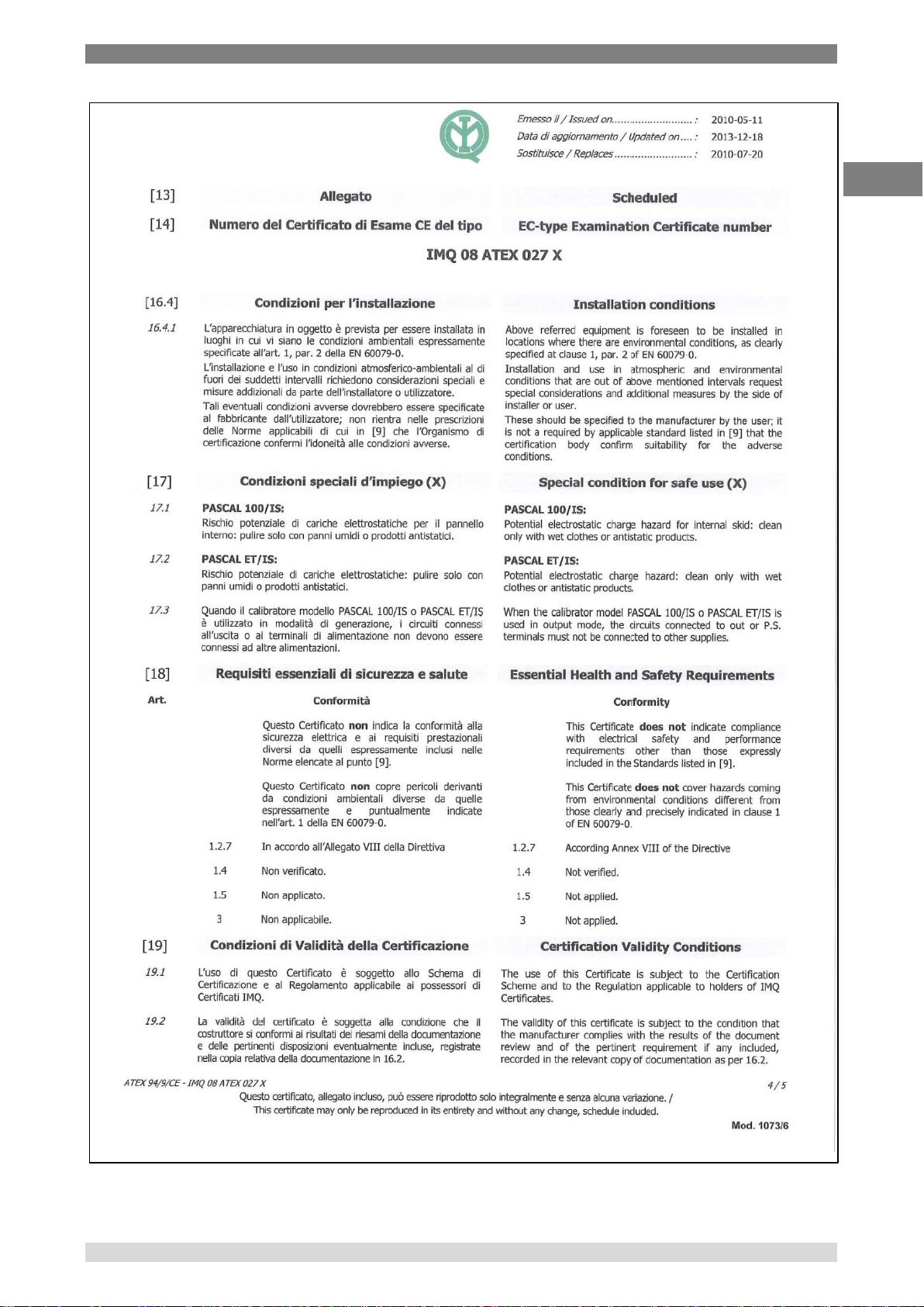
Appendix 1: ATEX Approval of Pascal 100/IS
GB
WIKA Operating Instruction, Model Pascal 100 and Pascal 100/IS 91
Page 92
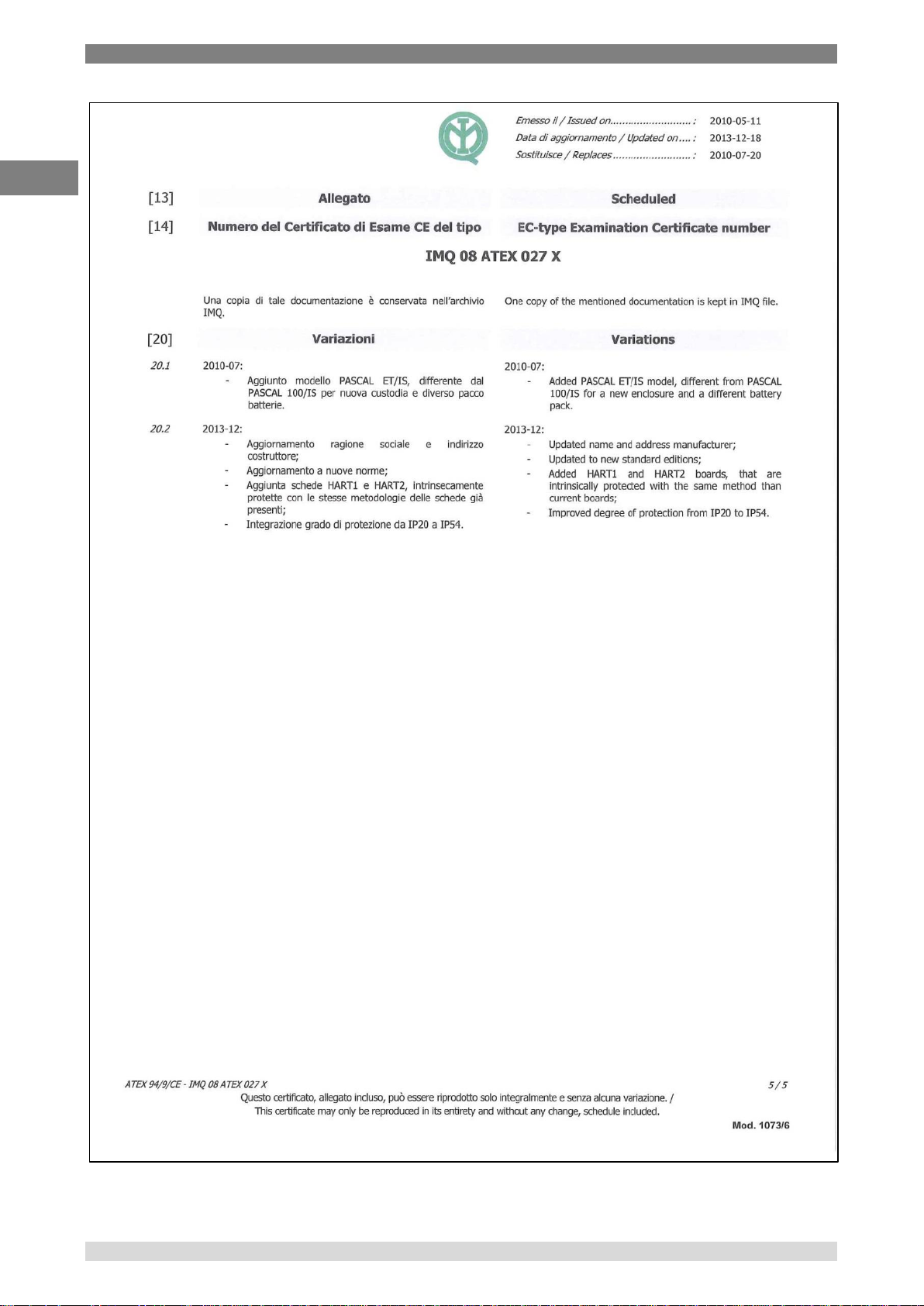
Appendix 1: ATEX Approval of Pascal 100/IS
GB
92 WIKA Operating Instruction, Pascal 100 and Pascal 100/IS
Page 93

WIKA Global
Europe
North America
Asia
Africa / Middle East
Austria
Romania
Canada
China
Egypt
WIKA Messgerätevertrieb
WIKA Instruments Romania
WIKA Instruments Ltd.
WIKA International Trading
WIKA Near East Ltd.
Ursula Wiegand
S.R.L.
Head Office
(Shanghai) Co., Ltd.
El-Serag City Towers
GmbH & Co. KG
Bucuresti, Sector 5
Edmonton, Alberta, T6N 1C8
A2615, NO.100, Zunyi Road
-Tower#2 - Office#67
1230 Vienna
Calea Rahovei Nr. 266-268
Tel. (+1) 780 46370-35
Changning District
Nasr City Cairo
Tel. (+43) 1 86916-31
Corp 61, Etaj 1
Fax: (+1) 780 46200-17
200051 Shanghai
Tel. (+20) 2 22733140
Fax: (+43) 1 86916-34
Tel. (+40) 21 4048327
E-Mail: info@wika.ca
Tel. (+86) 21 538525-72
Fax: (+20) 2 22703815
E-Mail: info@wika.at
Fax: (+40) 21 4563137
www.wika.ca
Fax: (+86) 21 538525-75
E-Mail: wika.repcairo@wika.de
www.wika.at
E-Mail: m.anghel@wika.ro
E-Mail: info@wika.cn
www.wika.com.eg
www.wika.ro
Mexico
www.wika.com.cn
Belarus
Instrumentos WIKA Mexico S.A.
Namibia
WIKA Belarus
Russia
de C.V.
WIKA Instrumentation
WIKA Instruments Namibia
Ul. Zaharova 50B
ZAO WIKA MERA
01210 Mexico D.F.
(Suzhou) Co., Ltd.
(Pty) Ltd.
Office 3H
127015 Moscow
Tel. (+52) 55 55466329
81, Ta Yuan Road
P.O. Box 31263
220088 Minsk
Tel. (+7) 495-648 01 80
Fax: (+52) 55 50205300
SND, Suzhou 215011
Pionierspark
Tel. (+375) 17-294 57 11
Fax: (+7) 495-648 01 81
E-Mail: ventas@wika.com
Tel. (+86) 512 6878 8000
Windhoek
Fax: (+375) 17-294 57 11
E-Mail: info@wika.ru
www.wika.com.mx
Fax: (+86) 512 6809 2321
Tel. (+26) 4 6123 8811
E-Mail: info@wika.by
www.wika.ru
E-Mail: info@wika.cn
Fax (+26) 4 6123 3403
www.wika.by
USA
www.wika.com.cn
E-Mail: info@wika.com.na
Serbia
WIKA Instrument Corporation
www.wika.com.na
Benelux
WIKA Merna Tehnika d.o.o.
Lawrenceville, GA 30043
India
WIKA Benelux
Sime Solaje 15
Tel. (+1) 770 5138200
WIKA Instruments India Pvt. Ltd.
South Africa
6101 WX Echt
11060 Belgrade
Fax: (+1) 770 3385118
Village Kesnand, Wagholi
WIKA Instruments (Pty.) Ltd
Tel. (+31) 475 535-500
Tel. (+381) 11 2763722
E-Mail: info@wika.com
Pune - 412 207
Gardenview,
Fax: (+31) 475 535-446
Fax: (+381) 11 753674
www.wika.com
Tel. (+91) 20 66293-200
Johannesburg 2047
E-Mail: info@wika.nl
E-Mail: info@wika.co.yu
Fax: (+91) 20 66293-325
Tel. (+27) 11 62100-00
www.wika.nl
www.wika.co.yu
WIKA Instrument Corporation
E-Mail: sales@wika.co.in
Fax: (+27) 11 62100-59
Houston Facility
www.wika.co.in
E-Mail: sales@wika.co.za
Bulgaria
Spain
950 Hall Court
www.wika.co.za
WIKA Bulgaria EOOD
Instrumentos WIKA, S.A.
Deer Park, TX 77536
Japan
Bul. „Al. Stamboliiski“ 205
C/Josep Carner, 11-17
Tel. (+1) 713-475 0022
WIKA Japan K. K.
United Arab Emirates
1309 Sofia
08205 Sabadell (Barcelona)
Fax (+1) 713-475 0011
Tokyo 105-0023
WIKA Middle East FZE
Tel. (+359) 2 82138-10
Tel. (+34) 933 938630
E-mail: info@wikahouston.com
Tel. (+81) 3 543966-73
Jebel Ali, Dubai
Fax: (+359) 2 82138-13
Fax: (+34) 933 938666
www.wika.com
Fax: (+81) 3 543966-74
Tel. (+971) 4 8839-090
E-Mail: t.antonov@wika.bg
E-Mail: info@wika.es
E-Mail: info@wika.co.jp
Fax: (+971) 4 8839-198
www.wika.es
Mensor Corporation
E-Mail:wikame@emirates.net.ae
Croatia
201 Barnes Drive
Kazakhstan
www.wika.ae
Switzerland
San Marcos, TX 78666
TOO WIKA Kazakhstan
.
WIKA Croatia d.o.o.
MANOMETER AG
Tel. (+1) 512 3964200-15
050050
.
Hrastovicka 19
6285 Hitzkirch
Fax (+1) 512 3961820
050050 Almaty, Kazakhstan
Australia
10250 Zagreb-Lucko
Tel. (+41) 41 91972-72
E-Mail: sales@mensor.com
Tel. (+7) 32 72330848
.
Tel. (+385) 1 6531034
Fax: (+41) 41 91972-73
www.mensor.com
Fax: (+7) 32 72789905
Australia
Fax: (+385) 1 6531357
E-Mail: info@manometer.ch
E-Mail: info@wika.kz
WIKA Australia Pty. Ltd.
E-Mail: info@wika.hr
www.manometer.ch
.
www.wika.kz
Rydalmere, NSW 2116
www.wika.hr
_
South America
Tel. (+61) 2 88455222
_
Turkey
Korea
Fax: (+61) 2 96844767
Finland
WIKA Instruments Istanbul
Argentina
WIKA Korea Ltd.
E-Mail: sales@wika.com.au
WIKA Finland Oy
Basinc ve Sicaklik Ölcme
WIKA Argentina S.A.
#569-21 Gasan-dong
www.wika.com.au
00210 Helsinki
Cihazlari
Buenos Aires
Seoul 153-771 Korea
Tel. (+358) 9-682 49 20
Ith. Ihr. ve Tic. Ltd. Sti.
Tel. (+54) 11 47301800
Tel. (+82) 2 869 05 05
New Zealand
Fax: (+358) 9-682 49 270
Bayraktar Bulvari No. 17
Fax: (+54) 11 47610050
Fax (+82) 2 869 05 25
WIKA Instruments Limited
E-Mail: info@wika.fi
34775 Yukari Dudullu - Istanbul
E-Mail: info@wika.com.ar
E-Mail: info@wika.co.kr
Unit 7 / 49 Sainsbury Road
www.wika.fi
Tel. (+90) 216 41590-66
www.wika.com.ar
www.wika.co.kr
St Lukes - Auckland 1025
.
Fax: (+90) 216 41590-97
Tel. (+64) 9 8479020
France
E-Mail: info@wika.com.tr
Brazil
Malaysia
Fax: (+64) 9 8465964
WIKA Instruments s.a.r.l.
www.wika.com.tr
WIKA do Brasil Ind. e Com. Ltda.
WIKA Instrumentation (M)
E-Mail: info@wika.co.nz
95610 Eragny-sur-Oise
.
CEP 18560-000 Iperó - SP
Sdn.Bhd
www.wika.co.nz
Tel. (+33) 1 343084-84
Ukraine
Tel. (+55) 15 34599700
47100 Puchong, Selangor
Fax: (+33) 1 343084-94
TOV WIKA Prylad
Fax: (+55) 15 32661650
Tel. (+60) 3 80 63 10 80
E-Mail: info@wika.fr
M. Raskovoy Str. 11, A
E-Mail: marketing@wika.com.br
Fax: (+60) 3 80 63 10 70
www.wika.fr
PO 200
www.wika.com.br
E-Mail: info@wika.com.my
.
.
02660 Kyiv
www.wika.com.my
.
Germany
Tel. (+38) 044 496-8380
Chile
.
WIKA Alexander Wiegand
Fax: (+38) 044 496-8380
WIKA Chile S.p.A.
Singapore
.
SE & Co. KG
E-Mail: info@wika.ua
Coronel Pereira 72
WIKA Instrumentation Pte. Ltd.
.
63911 Klingenberg
www.wika.ua
Oficina 101
569625 Singapore
.
Tel. (+49) 9372 132-0
.
Las Condes Santiago de Chile
Tel. (+65) 68 44 55 06
.
Fax: (+49) 9372 132-406
United Kingdom
Tel. (+56) 9 66084258
Fax: (+65) 68 44 55 07
.
E-Mail: info@wika.de
WIKA Instruments Ltd
www.wika.cl
E-Mail: info@wika.com.sg
.
www.wika.de
Merstham, Redhill RH13LG
www.wika.com.sg
.
.
Tel. (+44) 1737 644-008
. Italy
Fax: (+44) 1737 644-403
Taiwan
.
WIKA Italia Srl & C. Sas
E-Mail: info@wika.co.uk
WIKA Instrumentation Taiwan
.
20020 Arese (Milano)
www.wika.co.uk
Ltd. . Tel. (+39) 02 9386-11
Pinjen, Taoyuan
Fax: (+39) 02 9386-174
Tel. (+886) 3 420 6052
E-Mail: info@wika.it
Fax: (+886) 3 490 0080
www.wika.it
E-Mail: info@wika.com.tw
. www.wika.com.tw
Poland
WIKA Polska S.A.
Thailand
87-800 Wloclawek
WIKA Instrumentation Cor-
Tel. (+48) 542 3011-00
poration (Thailand) Co., Ltd
Fax: (+48) 542 3011-01
850/7 Ladkrabang Road,
E-Mail: info@wikapolska.pl
Ladkrabang
www.wikapolska.pl
Bangkok 10520
Tel. (+66) 2 326 6876-80
Fax: (+66) 2 326 6874
E-Mail: info@wika.co.th
www.wika.co.th
WIKA Operating Instruction, Model Pascal 100 and Pascal 100/IS 93
 Loading...