

Page 1
N-10 / N-11
Operating instructions
Pressure Transmitter
WIKA Instrument Corporation
1000 Wiegand Boulevard
Lawrenceville, GA 30043
Phone (770) 513 8200
Fax (770) 338 5118
E-Mail info@wika.com
www.wika.com
2450335.08 USA 04/2006
USA
N-10 N-11
Page 2
Contents
Page
1. Important details for your information
2. A quick overview for you 2
3. Abbreviations, signs and symbols3
4. Function and accessories 3-4
5. For your safety 4-6
6. Packaging 6
7. Starting, operation 6-13
8. Maintenance, spare parts 14
9. Trouble shooting 14
10. Storage, disposal 15
11. Control drawing FM, CSA 16
Current terms and conditions apply.
Details are available on www.wika.com
WIKA Global
Canada WIKA Instruments Ltd.
Germany WIKA Alexander Wiegand GmbH Co. KG
Singapore WIKA Instrumentation Pte. Ltd.
South Africa WIKA Instruments (Pty.) Ltd.
WIKA Instrument Corporation
A1000 Wiegand Boulevard
Lawrenceville, GA 30043
Phone (770) 513 8200
Fax (770) 338 5118
E-Mail info@wika.com
www.wika.com
2450335.08 USA 04/2006
Phone: (+1) 780/463-7035
E-Mail: info@wika.ca
Phone: (+49) 93 72/13 20
E-Mail: info@wika.de
Phone: (+65) 68 44 55 06
info@wika.com.sg
Phone: (+27) 11/6 21 00 00
E-Mail: sales@wika.co.za
Operating instructions
N-10, N-11
Pressure transmitter
-15
N-10 N-11
Page 3

1. Important details for your information / 2. A quick overview for you
USA
1. Important details for your information
Read these operating instructions before installing and starting the pressure transmitter. Keep
the operating instructions in a place that is accessible to all users at any time.
The following installation and operating instructions have been compiled by us with great care
but it is not feasible to take all possible applications into consideration. These installation and
operation instructions should meet the needs of most pressure measurement applications. If
questions remain regarding a specific application, you can obtain further information (data
sheets, instructions, etc.) via our Internet address (www.wika.com/www.wika.de) or contact
WIKA for additional technical support (see section7 Starting, Operation/Further information).
The product data sheet is designated as APE N-10.
WIKA pressure transmitters are carefully designed and manufactured using state-of-the-art
technology. Every component undergoes strict quality inspection before assembly and each
instrument is fully tested prior to shipment.
Use of the product in accordance with the intended use N-10, N-11:
Use the non-incendive pressure transmitter for pressure measurement in hazardous areas.
Certificate FM/CSA: Pressure transmitter for operation in hazardous areas in compliance
with the respective certificate (see Control drawing No. 2245906, section 11).
FM / CSA Approval ratings: Non-incendive
Dust-ignitionproof for Class II and III, Division 1, Groups E, F, and G.
Non-incendive for Class I Division 2 Groups A, B, C and D
FM standards according to FMRC 3600, 3611, 3810
CSA Standard C22.2 No. 0-M1991, 0.4-M1982, 25-M1966, 94-M1991,
142-M1987, 213-M1987, UL 50, UL 508, UL 1203, UL 1604
Knowledge required: Install and start the pressure transmitter only if you are familiar with the
relevant regulations and directives of your country and if you have the qualification required.
You have to be acquainted with NEC. Depending on the operating conditions of your
application you have to have the corresponding knowledge, e.g. of aggressive media.
2. A quick overview for you
If you want to get a quick overview, read Chapters 3, 5, 7 and 10. There you will get some
short safety instructions and important information on your product and its starting.
2 WIKA Operating instructions N-10, N-11
2. A quick overview for you/3. Abbreviations, signs and symbols/4. Function
Read these chapters in any case. Get some more detailed information on this product in
Chapters 4 Function and accessories and 6 Packaging. Read Chapter 8 for
Maintenance. In the case of failures please refer to Chapter 9.
3. Abbreviations, signs and symbols
Potential danger of life or of
severe injuries.
!
Warning
Warning
Caution
2-wire Two connection lines are intended for the voltage supply.
3-wire Two connection lines are intended for the voltage supply.
UB+/Sig+ Positive supply / measurement connection
OV/Sig- Negative supply / measurement connection
CSA Canadian Standard Association
FM Factory Mutual
Potential danger of life or of
severe injuries due to catapulting
parts.
Potential danger of burns due to
hot surfaces.
Notice, important information,
malfunction.
Power supply
The supply current is the measurement signal.
One connection line is intended for the measurement signal.
The product was tested and certified by FM Approvals. It complies
with the applicable US-American
standards on safety (including
explosion protection).
The product was tested and certified by CSA International. It complies with the applicable Canadian
and US-American standards on
safety (including explosion protection).
Load (e.g. display)
4. Function and accessories
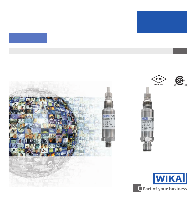
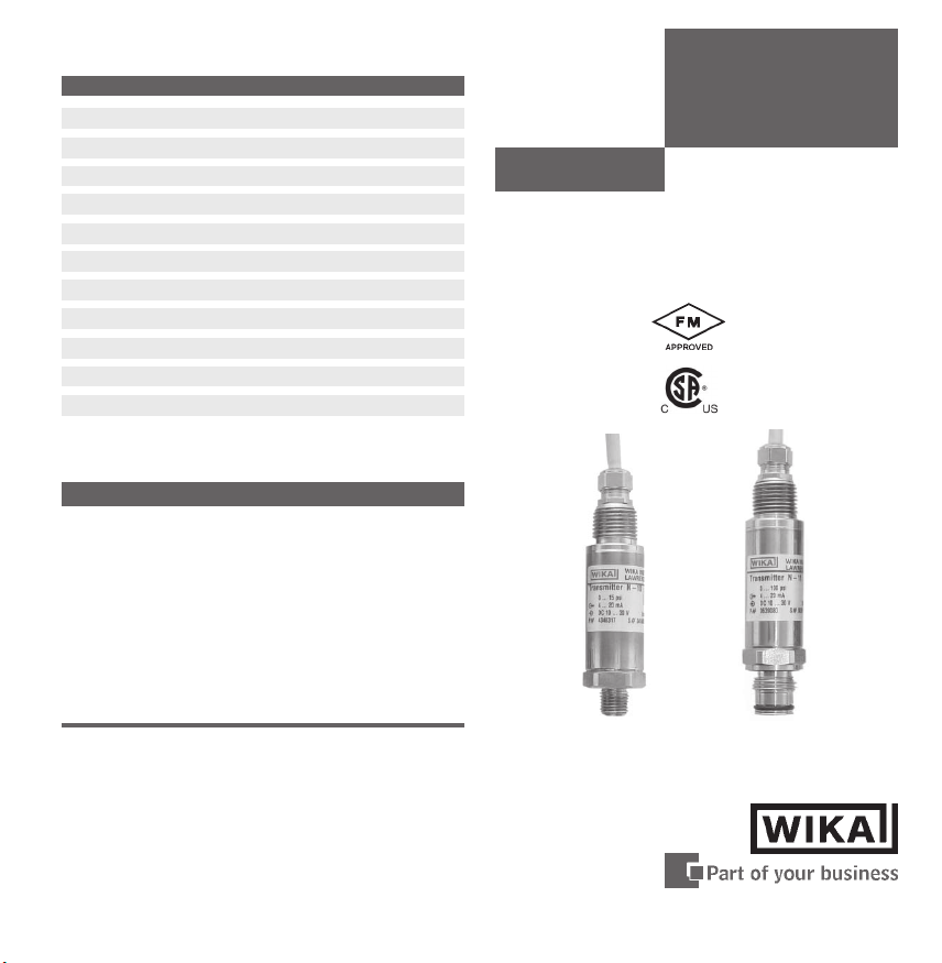
N-10: Standard pressure connection (non-incendive).
N-11: Pressure connection with flush diaphragm (non-incendive) for highly viscous
or solids entrained media which might clog the pressure port.
2450335.08 USA 04/2006
2450335.08 USA 04/2006
USA
3WIKA Operating instructions N-10, N-11
Page 4

4. Function and accessories / 5. For your safety
Function: With the pressure transmitter you measure the pressure of your application, which
is trans-formed into an electric signal. This electric signal changes in proportion to the
pressure and can be evaluated correspondingly.
Accessories: For details about the accessories, please refer to WIKAs price list, WIKAs
product catalog on CD or WIKAs web site www.wika.de. Please refer to our data sheet
Pressure gauge sealing washers AC 09.08 in WIKAs product catalog Pressure and
Temperature Measurement or our web site www.wika.de for details about sealing washers.
USA
5. For your safety
n Select the appropriate pressure transmitter with regard to scale range,
!
Warning
n Open pressure connections only after the system is without pressure!
n Please make sure that the pressure transmitter is only used within the overload
n Observe the ambient and working conditions outlined in section 7 Technical data.
n Ensure that the pressure transmitter is only operated in accordance with the
n Do not interfere with or change the pressure transmitter in any other way than
n Remove the pressure transmitter from service and mark it to prevent it from being
n Take precautions with regard to remaining media in removed pressure
n Have repairs performed by the manufacturer only.
performance and specific measurement conditions prior to installing and
starting the instrument.
n Observe the relevant national regulations (e.g.: NEC, CEC) and observe the
applicable standards and directives for special applications (e.g. with
dangerous media such as oxygen, acetylene, flammable gases or liquids and
toxic gases or liquids and with refrigeration plants or compressors).
If you do not observe the appropriate regulations, serious injuries and/or
damage can occur!
threshold limit all the times!
provisions, i.e. as described in the following instructions.
described in these operating instructions
used again accidentally, if it becomes damaged or unsafe for operation.
transmitter. Remaining media in the pressure port may be hazardous or toxic!
.
5. For your safety
Special advice for hazardous environments
n Consider the details given in the respective specifications for explosion hazard
!
Warning
n Observe the technical data for the use of the pressure transmitter in connection with
n Protect the diaphragm against any contact with abrasive substances and pressure
n Ensure that the pressure transmitter is mounted in a shielded section and protect it
n Use a supply voltage with power limitation P
n Ensure that the power supply is limited to U<42 V DC even in the case of malfunction.
n Do not open the instrument (e. g. for adjustment) in potentially explosive atmospheres!
n Observe the permissible surface temperatures applicable for this range according to
n Do not exceed the nominal pressure range for a prolonged period of time, because
n Do not disconnect the electrical connection while under voltage!
Special wiring advice
!
Warning
use of the country concerned (e.g.: NEC, CEC).
If you do not observe these stipulations, serious injuries and/or damage can
occur.
aggressive / corrosive media and for the avoidance of mechanical hazards.
peaks and do not touch it with tools. If you damage the diaphragm, the approval
ratings are not longer valid (FM, CSA)!
against shocks.
< 1W.
the defined temperature classes.
this can lead to an inadmissible heating of the case.
n Attempting to remove the cable connection will damage the transmitter and
void the factory warranty and FM approval.
n The electrical connection provided on the transmitter should be used as
originally supplied and not bypassed or modified (other than cable length).
Improper installation or modification of the electrical connection will void the
hazardous area approval rating.
n Always connect the case to earth to protect the pressure transmitter against
electromagnetic fields and electrostatic charges.
USA
4 WIKA Operating instructions N-10, N-11
2450335.08 USA 04/2006
2450335.08 USA 04/2006
5WIKA Operating instructions N-10, N-11
Page 5

5. For your safety / 6. Packaging / 7. Starting, operation
Special wiring advice
Warning
n Connect the shield to ground exclusively in safe (i.e. non-hazardous) areas in
!
accordance with NEC, CEC. Ensure that with flying leads the shield is always
connected to ground on the instrument side by the manufacturer.
n Cover flying leads with fine wires by an end splice (cable preparation).
USA
6. Packaging
n Inspect the pressure transmitter for possible damage during transportation.
Should there be any obvious damage, inform the transport company and WIKA
without delay.
n Keep the packaging, as it offers optimal protection during transportation
(e.g. changing installation location, shipment for repair).
In order to protect the diaphragm, the pressure connection of the instrument N-11 is provided
with a special protection cap.
n Remove this protection cap only just before installing the pressure transmitter
in order to prevent any damage to the diaphragm.
n Mount the protection cap when removing and transporting the instrument.
7. Starting, operation
Has everything been supplied?
Check the scope of supply:
n Completely assembled pressure transmitters; with flush version N-11 including
pre-assembled sealings and protection cap.
Required tools: wrench (flats 27), screw driver
Diaphragm test for your safety
It is necessary that before starting the pressure transmitter you test the diaphragm, as this is
a safety-relevant component.
n Pay attention to any liquid leaking out, for this points to a diaphragm damage.
n Check the diaphragm visually for any damage.
!
Warning
n Use the pressure transmitter only if the diaphragm is undamaged.
n Use the pressure transmitter only if it is in a faultless condition as far as the
safety-relevant features are concerned.
6 WIKA Operating instructions N-10, N-11
7. Starting, operation
Installation
n Remove the protection cap only just before installation and absolutely avoid
any damage to the diaphragm during installation as well.
n Ensure that the cablediameter you select fits to the cable gland of the
connector. Ensure that the cable gland of the mounted connector is positioned
correctly and that the sealings are available and undamaged. Tighten the
threaded connection and check the correct position of the sealings in order to
ensure the ingress protection.
n When mounting the instrument, ensure that the sealing faces of the instrument
and the measuring point are clean and undamaged.
n When screwing the transmitter in, ensure that the threads are not jammed.
n Screw in or unscrew the instrument only via the flats using a suitable tool and
and the prescribed torque. Do not use the case as working surface for
screwing in or unscrewing the instrument.
n Please observe the following when selecting
the cable:
when selecting the cable length, ensure that it is 3x longer than the cable
length required, so that the cable can be pulled to different locations.
n Switch on the operating voltage only after establishing the electrical
!
Warning
For tapped holes and welding sockets please see Technical Information IN 00.14
for download at www.wika.de -Service
2450335.08 USA 04/2006
2450335.08 USA 04/2006
connection in order to avoid any spark formation.
USA
7WIKA Operating instructions N-10, N-11
Page 6

7. Starting, operation
For Model N-10
you have to
provide for a
sealing element;
Use to install
the transmitter
process
connection
max. 50 Nm
Wiring
Ingress protection per IEC 60529 (The ingress
protection classes specified only apply while
the pressure transmitter is connected with
female connectors that provide the corresponding ingress protection).
Please make sure that the ends of cables with
flying leads do not allow any ingress of
moisture.
(D) Mounting hole
exceptions are
instruments with
self-sealing
threads (e.g.
NPT thread).
For Model N-11
the sealing ring
is included in
delivery.
Product label (example)
Coded manufacture date
Pressure range
Signal
Power Supply
Product No.
P #
S #
Serial No.
PIN assignment
(2)
(3)
(4)
(1)
(5)
(6)
USA
Female
connector
Sealing
Clamping nut,
Male connector,
Case with
pressure connection
7. Starting, operation
1. Loosen the screw (1).
2. Loosen the cable gland (2).
3. Pull the angle housing (5), with the terminal block (6) inside, away from the
instrument.
4. Using the head of a small screwdriver in the mounting hole (D), lever the
terminal block (6) out of the angle housing (5). In order not to damage the
sealing of the angle housing, do not try to push the terminal block (6) out using
the screw hole (1) or the cable gland (2).
5. Ensure that the conductor outer diameter you select is matched to the angle
housings cable gland. Slide the cable through the cable gland nut (2),
washer (3), gland seal (4) and angle housing (5).
6. Connect the flying leads to the screw terminals on the terminal block (6) in
accordance with the pin-assignment drawing.
7. Press the terminal block (6) back into the angle housing (5).
8. Tighten the cable gland (2) around the cable. Make sure that the sealing isnt
damaged and that the cable gland and seals are assembled correctly in order
to ensure ingress protection.
9. Place the flat, square gasket over the connection pins on the top of the instrument housing.
10. Slide the terminal block (6) onto the connection pins.
11. Secure the angle housing (5) and terminal block (6) to the instrument with the
screw (1).
L-connector DIN EN
175301-803 /
IP 65 (NEMA 5) / Order
code: AX
2-wire
USA
3-wire
8 WIKA Operating instructions N-10, N-11
2450335.08 USA 04/2006
2450335.08 USA 04/2006
9WIKA Operating instructions N-10, N-11
Page 7

7. Starting, operation
}
}
}
Cable with 1,6 m (6 foot)
length, IP 67 (NEMA 4x) /
Order code: 2X
2-wire
3-wire
brown
green
screen / case
USA
brown
white
green
screen / case
Specifications Model N-10, N-11
Pressure ranges psi 5 10 15 25 30 60 100 200
Over pressure safety psi 29 58 72 145 145 240 500 1160
Burst pressure psi 35 69 87 170 170 290 600 1390
Pressure ranges psi 300 500 1000 1500 2000 3000 5000
Over pressure safety psi 1160 1160 1740 2900 4600 7200 11,600
Burst pressure psi 1390 5800 7970 11,600 14,500 17,400 24,650
Pressure ranges psi 8000 10000 1)15000
1)
Over pressure safety psi 17,400 17,400 21,750
Burst pressure psi 34,800 2)34,800 43,500
{Vacuum, gauge pressure, compound range, absolute pressure are available}
1)
Only Model N-10.
2)
For model N-11: the value specified in the table applies only when sealing is
realised with the sealing ring underneath the hex. Otherwise max. 21,000 psi applies.
Materials
Wetted parts (other materials see WIKA diaphragm seal program)
n
Model N-10
Ø
Model N-11 Stainless steel {Hastelloy C4}
Ø
Stainless steel (> 300 psi stainless steel and Elgiloy®)
O-ring: NBR {FPM/FKM}
10 WIKA Operating instructions N-10, N-11
2)
7. Starting, operation
Specifications Model N-10, N-11
n Case Stainless steel
Internal transmission fluid Synthetic oil (not for N-10 with pressure ranges > 300 psi)
Power supply U
B
Signal output and
maximum load R
A
Adjustability zero/span % + 10 via potentiometers inside the instrument
Response time (10 ... 90 %) ms < 1 (< 10 ms at medium temperaturs below < -22 °F / -30 °C
Dielectric strength DC V 500
Accuracy % of span
Non-linearity % of span
1-year stability % of span
Permissible temperature of
n Medium
n Ambience
n Storage
4)
4)
4)
Compensated temp range 0 ... +80 °C 32 ... +176 °F
Temperature coefficients in
compensated temp range
n Mean TC of zero % of span
Mean TC of range
n
Approval authority
2450335.08 USA 04/2006
2450335.08 USA 04/2006
UB in DC V
10 < U
30 with signal output 4 ... 20 mA, 2-wire
≤
B
6 < UB < 30 with signal output 1 ... 5 V, 3-wire low power
4 … 20 mA, 2-wire, R
R
in Ohm 1 … 5 V, 3-wire, RA > 10000
A
≤ (UB–10 V) / 0.02 A
A
for pressure ranges up to 300 psi or with flush diaphragm)
0.25 (BFSL)
≤
% of span
3)
Including non-linearity, hysteresis, non-repeatability, zero signal and full scale error
(corresponds to error of measurement per IEC 61298-2).
Adjusted in vertical mounting position with lower pressure connection.
3)
0.5
≤
0.2 (BFSL) according to IEC 61298-2
≤
0.2 (at reference conditions)
≤
-22 ... +212 °F{-40…+221 °F} -30 ... +100 °C{-40…+105°C
-22 ... +212 °F{-40…+221 °F} -30 ... +100 °C{-40…+105°C
4)
lso complies with EN 50178, Tab. 7, Operation (C) 4K4H, Storage (D) 1K4,
A
Transport (E) 2K3
% of span
-40 ... +221 °F{-58…+221 °F} -40 ... +105 °C{-50…+105°C
0.2 / 10 K (< 0,4 for pressure range < 250 mbar)
≤
0.2 / 10 K
≤
Factory mutual (FM / CSA) non-incendive with entity
n
Approval for: Class 1, Division 2, Groups A, B, C and D
USA
11WIKA Operating instructions N-10, N-11
Page 8

7. Starting, operation
Specifications Model N-10, N-11
Dust ignitionproof for:
n
Class II and III, Division 1, Groups E, F and G
Maximum electrical ratings 30 V, 20 mA
FM standards according to FMRC 3600, 3611 and 3811
HF-immunity V/m 10
BURST KV 4
Shock resistance g 1000 according to IEC 60068-2-27 (mechanical shock)
Vibration resistance g 20 according to IEC 60068-2-6 (vibration resonance)
Wiring protection Protected against reverse polarity and short circuiting
on the instrument side
Mass lb Approx. 0.4
{ } Items in curved brackets are optional extras for additional price.
USA
n When designing your plant, take into account that the stated values (e.g. burst
pressure, over pressure safety) apply depending on the material, thread and
sealing element used.
n With all pressure ranges, except for those mentioned above, the technical
specifications are subject to change.
Functional test
n Open pressure connections only after the system is without pressure!
n Observe the ambient and working conditions outlined in section 7 Technical
Warning
data."
n Please make sure that the pressure transmitter is only used within the overload
threshold limit at all times!
When touching the pressure transmitter, keep in mind that the surfaces of the
instrument components might get hot during operation.
Caution
The output signal must be proportional to the pressure. If not, this might point
to a damage of the diaphragm. In that case refer to chapter 9Troubleshooting.
12 WIKA Operating instructions N-10, N-11
7. Starting, operation
Adjustment of zero point / span (only for pressure transmitter with clamping)
n Do not open the instrument (e. g. for adjustment) in potentially explosive
!
Warning
n Make sure wires are not cut or pinched
during disassembly and reassembly of the
connector.
n Remove the female connector. Open the
pressure transmitter by detaching the
clamping nut (see Fig. A ). Carefully
remove the male connector from the case.
n Adjust the zero point (Z) (see Fig. B )
by generating the lower limit of the
pressure range.
n Adjust the span (S) by generating the
higher limit of the pressure range.
n Check the zero point.
n If the zero point is incorrect, repeat
procedure as required.
n Reassemble the instrument carefully.
Make sure all sealings and o-rings are not
damaged and correctly installed to assure
the rated moisture ingress protection.
Shutdown
2450335.08 USA 04/2006
2450335.08 USA 04/2006
atmospheres!
We do not recommend to adjust the span potentiometer. It is used for
adjustment ex factory and should not be adjusted by you unless you have
adequate calibration equipment at your disposal (at least three times more
accurate than the instrument being tested).
A
A
Recommended recalibration cycle: 1 year
For further information (770) 513 8200
1) Switch off the operating voltage.
2) Pull the connector or disconnect the cable.
Female
connector
Sealing
Clamping
nut
Male
connector
Sealing
Case with
pressure
connection
USA
B
S = Span
Z = Zero
13WIKA Operating instructions N-10, N-11
Page 9

8. Maintenance, spare parts / 9. Trouble shooting
USA
8. Maintenance, spare parts: WIKA pressure transmitters require no maintenance!
n Open pressure connections only after the system is without pressure!
Warning
n Take precautions with regard to remaining media in removed pressure
!
Warning
transmitters. Remaining media in the pressure port may be hazardous or toxic!
n Remove the pressure transmitter from service and mark it to prevent it from
being used again accidentally, if it becomes damaged or unsafe for operation.
n Have repairs performed by the manufacturer only.
Do not insert any pointed or hard objects into the pressure port for cleaning to
prevent damage to the diaphragm of the pressure connection.
Spare parts: For spare part details refer to our current stock price list, the CD catalog or
contact our sales department.
9. Trouble shooting
Problem Possible cause Remedy
No output Power supply failure Check power supply
Open wiring Check continuity
Wiring reversed Correct polarity
No pressure or port blocked Check pressure port
Transmitter failure due to wrong
Supply voltage or power surge Replace transmitter
Output steady as pressure Pressure port blocked Check pressure port
changes Transmitter over-pressurized Replace transmitter
Transmitter failure due to wrong
Supply voltage or power surge Replace Transmitter
Full span output low Supply voltage too low Check supply voltage
Load impedance too high or too low Adjust load or supply voltage
Transmitter over-pressurized Recalibrate Transmitter
Replace Transmitter *
14 WIKA Operating instructions N-10, N-11
)
9. Trouble shooting / 10. Storage, disposal
Problem Possible cause Remedy
Zero signal too low or too high Transmitter over-pressurized Recalibrate Transmitter
Replace Transmitter *
Non-linear output Transmitter over-pressurized Replace Transmitter
*)Test the system for proper operation after adjustments are made. An excessive change in the output signal that
cannot be corrected by calibration indicates possible transmitter damage. This may cause the output to be non-linear,
requiring transmitter replacement.
)
If the problem persists, contact our sales department.
USA, Canada: If the problem continues, contact WIKA or an authorized agent for assistance.
If the pressure transmitter must be returned obtain an RMA (return material authorization)
number and shipping instructions from the place of purchase. Be sure to include detailed
information about the problem. Pressure transmitters received by WIKA without a valid RMA
number will not be accepted.
Process material certificate (Contamination declaration for returned goods)
Purge / clean dismounted instruments before returning them.
Service of instruments can only take place safely when a contamination declaration has been
submitted and fully filled-in. This declaration contains information on all materials with which
the instrument has come into contact, either through installation, test purposes, or cleaning.
You can find a contamination declaration on our internet site (www.wika.de / www.wika.com).
10. Storage, disposal
When storing or disposing of the pressure transmitter, take precautions with
regard to remaining media in removed pressure transmitters. Remaining media
in the pressure port may be hazardous or toxic!
Mount the protection cap when storing the pressure transmitter in order to
prevent any damage to the diaphragm.
Dispose of instrument components and packaging materials in accordance
with the respective waste treatment and disposal regulations of the region or
country to which the instrument is supplied.
2450335.08 USA 04/2006
!
Warning
Storage
Disposal
2450335.08 USA 04/2006
USA
15WIKA Operating instructions N-10, N-11
Page 10

11. Control Drawing
11. Control Drawing (FM, CSA)
USA
Control drawing S-No. 2245906.03
SERIES N-10, N-11
APPROVED/ CERTIFIED
NONINCENDIVE TRANSMITTER
4-20 mA
This Equipment is suitable for Locations:
Class I, Division 2, Groups A, B, C, D
Class II, Division 1, Group E, F, G
1-5 V,0-5 V
UB+UB+ Sig+
0V / Sig-0V / Sig-
Sig+
1
2
3
4
CONTROL EQUIPMENT
BROWN
GREEN
WHITE
BARE
NON-HAZARDOUS LOCATIONHAZARDOUS LOCATION
Notes U.S. Installations
1 Install per NATIONAL ELECTRICAL
CODE and local, as applicable.
2 To maintain type 4X sealing of series
N-10 / N-11-transmitter use thread
sealant when installing conduit.
WIKA reserves the right to alter these technical specifications.
16 WIKA Operating instructions N-10, N-11
2450335.08 USA 04/2006
 Loading...