

Page 1
Hazardous Area Non-incendive Transmitters
Model N-10, N-11
Applications
■
Natural gas compressors
■
Wellhead monitoring
■
Pipeline pressure
■
General industrial applications
Special Features
Electronic
Pressure Measurement
Datasheet N-10, N-11
■
FM /CSA approved Non-incedive for Class I Division 2,
Dust-ignitionproof for Class II, Division 1
■
Engineered to meet the harsh demands of
gas compressor applications
■
Does not require the use of intrinsically safe barriers
■
NACE MR-01-75 compliant wetted parts
■
4-20 mA or low power 1-5 volt output signals available
Description
Type N-10 pressure transmitters are specically designed
to meet the durability and performance requirements of gas
compressor systems. These pressure transmitters feature an
industry standard 4-20 mA 2 wire signal output, NEMA 4X (IP
67) weather protection and are extremely resistant to pressure
spikes, vibration and moisture intrusion. NACE MR-01-75
compliance provides extra resistance against sulde stress
cracking when exposed to gases containing sulphur.
Type N-11 pressure transmitters feature a at, non-clogging
diaphragm. This is designed for use with viscous uids or
media containing particulates that could clog the pressure port
of the standard NPT version.
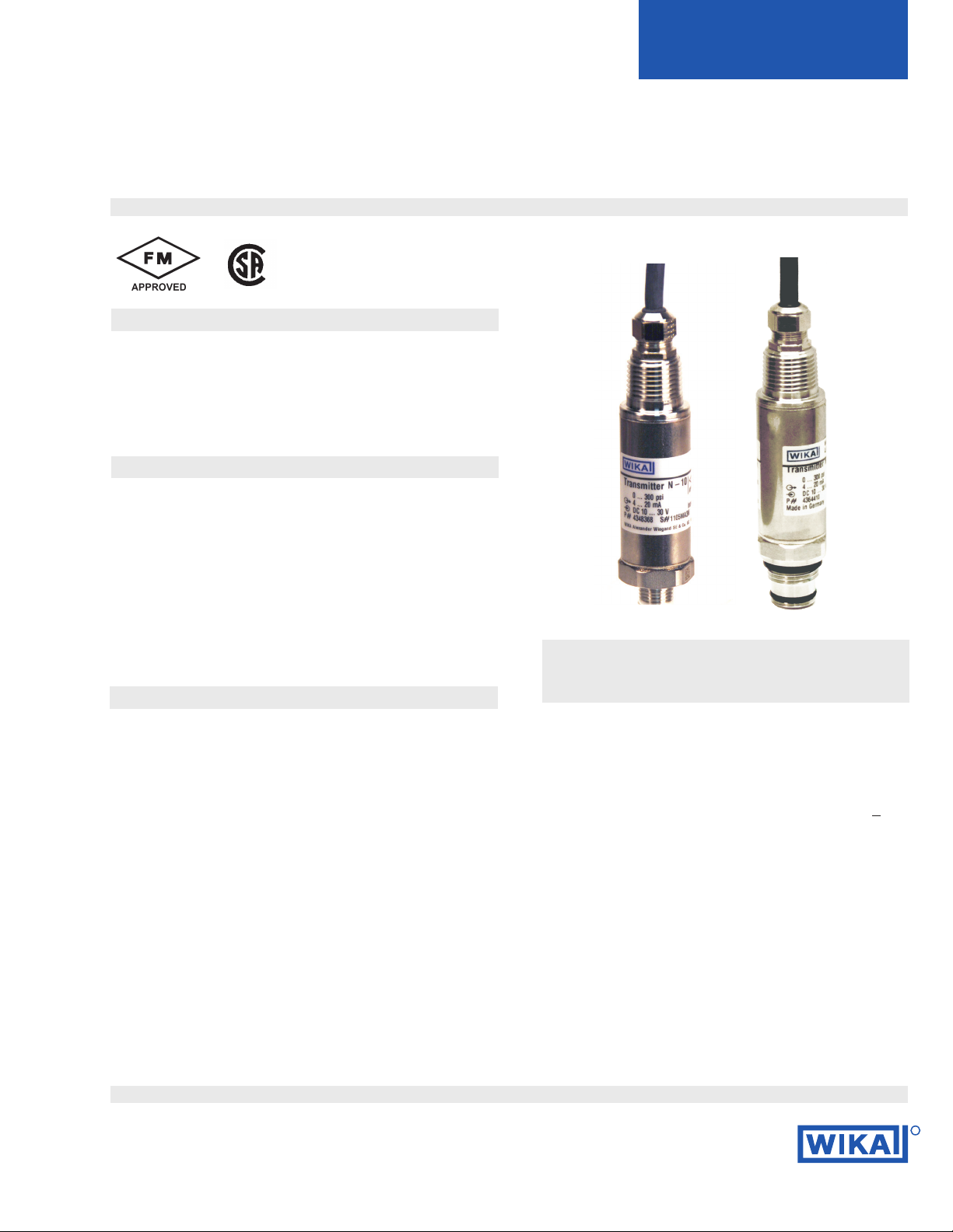
Left: N-10 pressure transmitter with NPT connection
Right: N-11 ush diaphragm pressure transmitter
The transmitters are engineered to meet Class I Division 2
non-incendive protection requirements, as well as Class II
Division 1 dust-ignition protection requirements in hazardous environments. Each undergoes extensive quality
control testing and calibration to achieve a linearity of <
0.25% full scale. In addition, each pressure transmitter is
temperature compensated to assure accuracy and long
term stability when exposed to severe ambient temperature
variations.
Datasheet N-10, N-11 · 11/2016
Page 1 of 4
R
Page 2

Specications Type N-10 / N-11
Pressure range 5 psi 10 psi 15 psi 25 psi 30 psi 60 psi 100 psi 200 psi 300 psi
Maximum pressure* 29 psi 58 psi 72 psi 145 psi 145 psi 240 psi 500 psi 1,160 psi 1,160 psi
Burst pressure** 35 psi 69 psi 87 psi 170 psi 170 psi 290 psi 600 psi 1,390 psi 1,390 psi
Pressure range 500 psi 1,000 psi 1,500 psi 2,000 psi 3,000 psi 5,000 psi 8,000 psi110,000 psi115,000 psi
Maximum pressure* 1,160 psi 1,740 psi 2,900 psi 4,600 psi 7,200 psi 11,600 psi 17,400 psi 17,400 psi 21,750 psi
Burst pressure** 5,800 psi 7,970 psi 11,600 psi 14,500 psi 17,400 psi 24,650 psi234,800 psi 34,800 psi 43,500 psi
{vacuum, gauge pressure, compound ranges, and absolute pressure references are available}
Materials
Wetted parts
N-10
N-11
Case
Nace compliant
Stainless steel (> 1,000 psi stainless steel and Elgiloy)
Stainless steel; O-ring: NBR {Viton or EPDM}
Stainless steel
Internal transmission uid Synthetic oil (only for pressure ranges up to 300 psi or ush diaphragm units)
Power supply U
B
DC V 10 < UB ≤ 30 for 4 ... 20 mA, 2-wire
6 < U
< 30 for 1 ... 5 V, 3-wire low power version
B
Signal output and 4…20 mA: RA ≤ (UB - 10 V) / 0,02 A with R
maximum load R
A
1 ... 5 V, 3-wire: RA > 10 kOhm
Response time (10 ... 90 %) ms ≤ 1 (≤ 10 ms when media temperatures are below –22 ° F ( -30 °C) for pressure
ranges up to 300 psi or with ush diaphragm)
Isolation voltage
Accuracy
3)
V
% of span
500
≤ 0.25 (BFSL)
% of span ≤ 0.5 (limit point calibration)
Non-repeatability % of span ≤ 0.05
Hysteresis % of span ≤ 0.1
1-year stability % of span ≤ 0.2 (at reference conditions)
Permissible temperature of
Medium
Ambient
Storage
-22 ... +176 °F -30 ... +80 °C (-40 °C only with NPT threads)
-22 ... +176 °F -30 ... +80 °C
-22 ... +221 °F -30 ... +105 °C
Compensated temp. range 32 ... +176 °F 0 ... +80 °C
Temperature coecients in
compensated temp range:
Mean TC of zero
Mean TC of range
Approval authority
% of span ≤ 0.2 / 10 K (< 0,4 for pressure range < 100 InWC)
% of span ≤ 0.2 / 10 K
Factory Mutual (FM) non-incendive with entity approval for:
Class 1, Division 2, Groups A, B, C, D
Dust ignition-proof for Class II, Division 1, Groups E,F and G
Vmax=30V, Imax=30mA, Pi=1W
Maximum electrical ratings
For 2wire system: Ci=22nF (ying leads: +0.2 nF/m) , Li=0mH (ying leads: +2µH/m)
For 3wire systems: Ci=140nF (ying leads: +0.2 nF/m) , Li=0mH (ying leads: +2µH/m)
FM Standards according to FMRC 3600, 3611, 3810
Ingress protection NEMA 4X (IP 67)
Shock resistance g 1,000 according to IEC 60068-2-27 (mechanical shock)
Vibration resistance g 20 according to IEC 60068-2-27 (vibration under resonant conditions)
Wiring protection Protected against reverse polarity, overvoltage, and short circuiting
Weight
* Pressure applied up to the maximum rating will cause no permanent change in specications but may lead to zero and span shifts
**Exceeding the burst pressure may result in destruction of the transmitter
1) Only Type N-10.
2) For Type N-11: the burst pressure is limited to 21,000 psi unless the pressure seal is accomplished by using the sealing ring underneath the hex.
3) Includes non-linearity, hysteresis and repeatability. Limit point calibration performed in vertical mounting position with pressure connection facing down.
4) Transmitters will function when exposed to these extended temperature ranges. The media, when exposed to temperature extremes, may change
characteristics that eect transmitter performance.
5) Wetted parts comply with recommendations per NACE MR0175. Environmental limits apply to certain materials. Consult latest standard for details.
{ } Items in curved brackets are options available at additional cost.
lb 0.4
5
in Ohm and UB in Volt
A
1
Datasheet N-10, N-11 · 11/2016Page 2 of 4
Page 3

Dimensions in inches (mm)
Electrical connection
6 foot cable with free ends
NEMA 4 / IP 67
Order code: 2X
1.06“ (27mm)
Case
N-10 pressure connections
1/4 NPT male
Order code: NB
.85” (21.5mm)
.51” (13mm)
1/ 2 NPT male
Order code: ND
.75”(19mm)
1.08”(27.5mm)
1.06“ (27mm)
2.28“ (58mm)
G 1/2
EN 837
Order code: GD
.79”(20mm)
1.12”(28.5mm)
.12”(3mm)
.32”(8mm)
O .24”
(6mm)
O .69”
(17.5mm)
G 1/4
EN 837
Order code: GB
.85”(21.5mm)
.51”(13mm)
.08”(2mm)
.08”(2mm)
O .20”
(5mm)
O .37”
(9.5mm)
N-11 ush diaphragm pressure connections
N-11 G 1
50 InWC to 25 psi
Order code: 85
Sealing ring
29.7x35.7x2.0
1.26”(31.9mm)
.81”(20.5mm)
.39”(10mm)
O-ring 26x2
N-11 G 1/2
30 psi to 5,000 psi
Order code: 86
1.22”(31mm)
.81”(20.5mm)
.39”(10mm)
Sealing ring
18.5x23.9x1.5
O-ring 15x2
Page 3 of 4Datasheet N-10, N-11 · 11/2016
Page 4

Matching P-1 weld insert adapters for N-11 ush diaphragm transmitters
weld
P-1 G1 weld insert adapter
Part # 1206974
for pressure ranges < 25 psi
Wiring details
6 foot cable with free
ends
Legend:
2-wire system
shield / case
P-1 G1/2 weld insert adapter
Part # 1097008
for pressure ranges > 30 psi
brown
green
Cross section view of P-1
adapter installed in pipe.
3-wire system
brown
white
green
shield / case
Sig+ output signal positive
UB+ power supply positive
0V power supply negative
Sig - output signal negative
Page 4 of 4
Specications and dimensions given in this data sheet represent the state of engineering at the time of printing.
Modications may take place and materials specied may be replaced by others without prior notice.
Datasheet N-10, N-11 · 11/2016
R
WIKA Instrument, LP
1000 Wiegand Boulevard
Lawrenceville, GA 30043
1-888-WIKA-USA /770-513-8200 (in GA)
Fax 770-338-5118
info@wika.com www.wika.com
 Loading...