

Page 1
Operating instructions
Betriebsanleitung
Mode d‘emploi
Manual de instrucciones
OEM pressure sensor, model MH-3
OEM-Drucksensor, Typ MH-3
Capteur de pression OEM, type MH-3
Sensor de presión para OEM, modelo MH-3
EN
DE
FR
ES
Examples/Beispiele/Exemples/Ejemplos
Page 2

EN
Operating instructions model MH-3
Betriebsanleitung Typ MH-3
DE
Page 3 - 22
Seite 23 - 42
FR
Mode d‘emploi
ES
Manual de instrucciones modelo
© 08/2015 WIKA Alexander Wiegand SE & Co. KG
All rights reserved. / Alle Rechte vorbehalten.
®
WIKA
is a registered trademark in various countries.
®
WIKA
ist eine geschützte Marke in verschiedenen Ländern.
Prior to starting any work, read the operating instructions!
Keep for later use!
type MH-3 Page 43 - 62
MH-3 Página 63 - 82
Vor Beginn aller Arbeiten Betriebsanleitung lesen!
Zum späteren Gebrauch aufbewahren!
Lire le mode d‘emploi avant de commencer toute opération !
A conserver pour une utilisation ultérieure !
¡Leer el manual de instrucciones antes de comenzar cualquier trabajo!
¡Guardar el manual para una eventual consulta!
2
WIKA operating instructions OEM pressure sensor, model MH-3
14136172.03 11/2019 EN/DE/FR/ES
Page 3

Contents
Contents
1. General information 4
2. Design and function 5
3. Safety 6
4. Transport, packaging and storage 8
5. Commissioning, operation 9
6. Faults 11
7. Maintenance and cleaning 12
8. Dismounting, return and disposal 13
9. Specifications 15
Declarations of conformity can be found online at www.wika.com
EN
14136172.03 11/2019 EN/DE/FR/ES
3WIKA operating instructions, OEM pressure sensor, model MH-3
Page 4

1. General information
1. General information
■
The instrument described in the operating instructions has been designed and
EN
manufactured using state-of-the-art technology. All components are subject to stringent quality and environmental criteria during production. Our management systems
are certified to ISO 9001 and ISO 14001.
■
These operating instructions contain important information on handling the instrument. Working safely requires that all safety instructions and work instructions are
observed.
■
Observe the relevant local accident prevention regulations and general safety regulations for the instrument's range of use.
■
The operating instructions are part of the product and must be kept in the immediate
vicinity of the instrument and readily accessible to skilled personnel at any time. Pass
the operating instructions on to the next operator or owner of the instrument.
■
Skilled personnel must have carefully read and understood the operating instructions
prior to beginning any work.
■
The general terms and conditions contained in the sales documentation shall apply.
■
Subject to technical modifications.
■
Further information:
- Internet address: www.wika.de / www.wika.com
- Relevant data sheet: PE 81.59
- Application consultant:
Tel.: +49 9372 132-0
Fax: +49 9372 132-406
info@wika.com
4
WIKA operating instructions, OEM pressure sensor, model MH-3
14136172.03 11/2019 EN/DE/FR/ES
Page 5
2. Design and function
2. Design and function
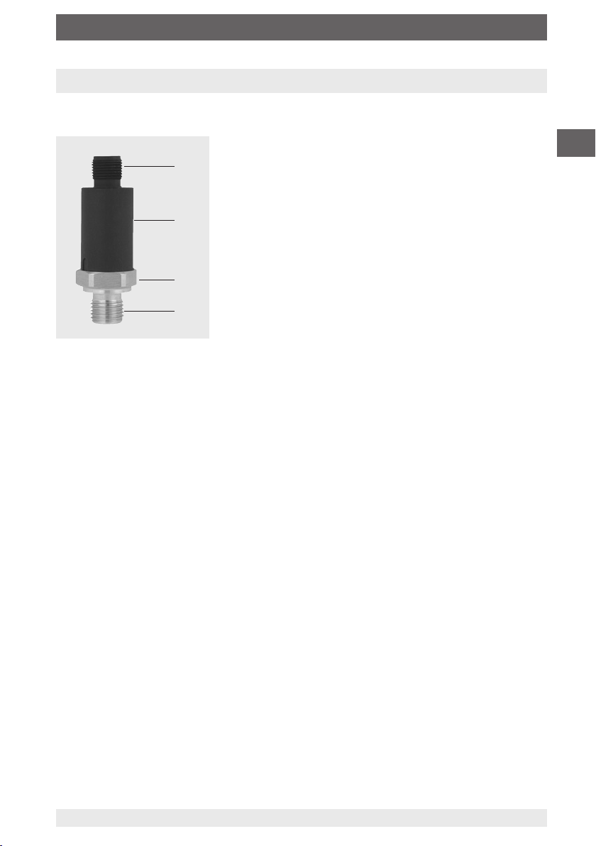
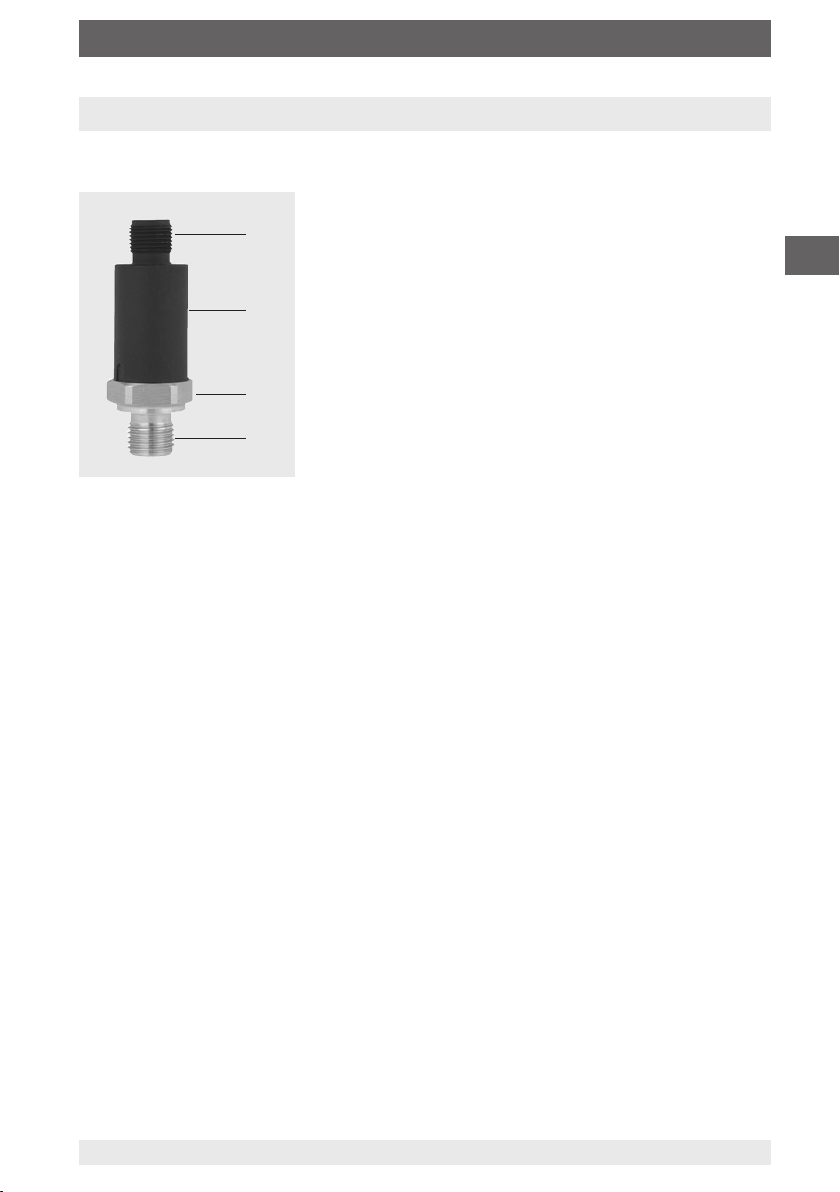
2.1 Overview
Electrical connection (depending on version)
Case
Process connection, spanner flats
Process connection, thread
2.2 Signal clamping (not for MH-3-HY)
The output signal of a pressure sensor can be above the nominal maximum signal
value, if no signal clamping has been set. Likewise, the output signal can also be below
the nominal minimum signal value. This undefined condition can cause an error in
the machine (software) of the customer. Signal clamping limits the output signal to a
minimum or maximum value which is to be defined by the customer.
EN
2.3 Diagnostic function
By means of the output signal, fault conditions can be detected and evaluated via
software. Thus it is possible to differentiate between permanent and temporary faults.
2.4 CDS system
All process connections are available with the CDS system. The diameter of the pressure port is reduced in order to counteract pressure spikes and cavitation.
2.5 Scope of delivery
■
Pressure sensor
■
Operating instructions (for model MH-3-HY)
Cross-check scope of delivery with delivery note.
14136172.03 11/2019 EN/DE/FR/ES
5WIKA operating instructions, OEM pressure sensor, model MH-3
Page 6
3. Safety
3. Safety
3.1 Explanation of symbols
EN
3.2 Intended use
The pressure sensor is used for measuring pressure. The measured pressure is output
as an electrical signal.
The pressure sensor model MH-3 is intended for use in mobile working machines.
The MH-3-HY pressure sensor for mobile hydrogen applications is typically used to
monitor tank pressure and the pressure after the reducing valve in hydrogen-powered
vehicles, especially industrial trucks, utility/municipal vehicles and buses. The exact
position of the sensor is therefore dependent upon the customer and application.
Only use the pressure sensor in applications that lie within its technical performance
limits (e.g. max. ambient temperature, material compatibility, ...).
→ For performance limits see chapter 9 “Specifications”.
The instrument has been designed and built solely for the intended use described here,
and may only be used accordingly.
WARNING!
... indicates a potentially dangerous situation that can result in serious
injury or death, if not avoided.
CAUTION!
... indicates a potentially dangerous situation that can result in light
injuries or damage to property or the environment, if not avoided.
Information
... points out useful tips, recommendations and information for efficient
and trouble-free operation.
The manufacturer shall not be liable for claims of any type based on operation contrary
to the intended use.
Technical restrictions
■
Any permanent operation in the overload range is not permitted. Above the operating
pressure, up to the overload limit, the pressure sensor is operating outside its specification. The overload limit is intended to prevent damage to the pressure sensor, as
part of a pressure vessel system, during the pressure containment test.
■
The overload limit must never be exceeded, even when failures occur in the end-use
application. Loads above the overload limit can cause irreversible damage, which can
lead, for example, to permanent measuring errors.
6
WIKA operating instructions, OEM pressure sensor, model MH-3
14136172.03 11/2019 EN/DE/FR/ES
Page 7

3. Safety
Specific notes based on the medium hydrogen (model MH-3-HY)
The sensor offered uses the wetted materials 2.4711 and 1.4404. These materials are
resistant to hydrogen embrittlement.
With a temperature of up to 30 °C, the stability under hydrogen influence is typically
1 %/year, maximum 3 %/year.
Due to hydrogen diffusion into the sensor structures, a signal drift can occur dependent
upon the time. The time until the occurrence of a relevant signal drift and the size of the
signal drift depends mainly on factors such as the temperature of the hydrogen, hydrogen content in the medium, and the diaphragm thickness of the pressure sensor used.
It is explicitly recommended for the user to test the selected product version for suitability in the intended application(s) with the specified ambient conditions.
3.3 Personnel qualification
Skilled personnel
Skilled personnel, authorised by the operator, are understood to be personnel who,
based on their technical training, knowledge of measurement and control technology and on their experience and knowledge of country-specific regulations, current
standards and directives, are capable of carrying out the work described and independently recognising potential hazards.
3.4 Personal protective equipment
The personal protective equipment is designed to protect the skilled personnel from
hazards that could impair their safety or health during work. When carrying out the
various tasks on and with the instrument, the skilled personnel must wear personal
protective equipment.
EN
Follow the instructions displayed in the work area regarding personal protective
equipment!
The requisite personal protective equipment must be provided by the operating company.
14136172.03 11/2019 EN/DE/FR/ES
7WIKA operating instructions, OEM pressure sensor, model MH-3
Page 8
3. Safety/4. Transport, packaging and storage
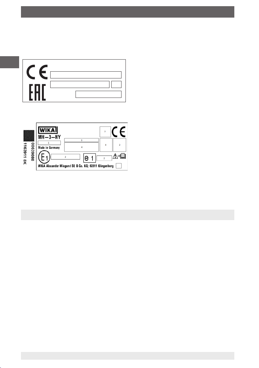
3.5 Labelling, safety marks
Product labels
EN
wika.com
1
2
MH-3
1 Product no. 3 Coded date of manufacture
2 Serial no. 4 Measuring range
1 Product no. 4 Specifications
2 Approvals 5 Coded date of manufacture
3 Nominal working pressure (NWP)
The nominal working pressure per 79/2009/EC corresponds to a nominal working pressure at 15 °C
4
4. Transport, packaging and storage
4.1 Transport
Check the pressure sensor for any damage that may have been caused by transport.
Obvious damage must be reported immediately.
3
5
4.2 Packaging and storage
Do not remove packaging until just before mounting.
Keep the packaging as it will provide optimum protection during transport (e.g. change
in installation site, sending for repair).
Permissible conditions at the place of storage:
■
Storage temperature see chapter 9 “Specifications”
■
Humidity: 67 % relative humidity (no condensation)
Avoid exposure to the following factors:
■
Direct sunlight or proximity to hot objects
■
Mechanical vibration, mechanical shock (putting it down hard)
■
Soot, vapour, dust and corrosive gases
■
Hazardous environments, flammable atmospheres
8
WIKA operating instructions, OEM pressure sensor, model MH-3
14136172.03 11/2019 EN/DE/FR/ES
Page 9
4.Transport, .../5. Commissioning, operation
Store the instrument in its original packaging in a location that fulfils the conditions
listed above. If the original packaging is not available, pack and store the instrument as
described below:
1. Wrap the instrument in an antistatic plastic film.
2. Place the instrument, along with shock-absorbent material, in the packaging.
3. If stored for a prolonged period of time (more than 30 days), place a bag containing a
desiccant inside the packaging.
5. Commissioning, operation
5.1 Mounting the instrument
Requirements for mounting point
The mounting point must meet the following conditions:
■
Sufficient space for a safe electrical installation.
■
Permissible ambient and medium temperatures remain within the performance limits.
Consider possible restrictions on the ambient temperature range caused by mating
connector used.
→ For performance limits see chapter 9 “Specifications”
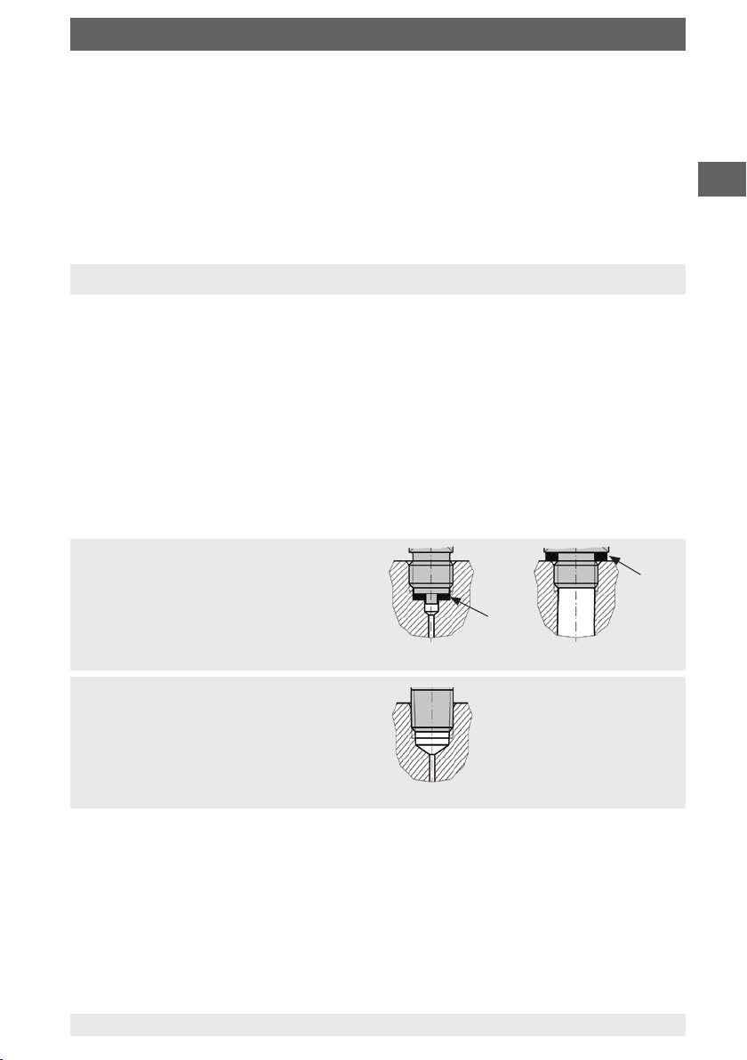
Sealing variants
EN
Parallel threads
Seal the sealing face with flat gasket, lens-type
sealing ring or WIKA profile sealing.
Tapered threads
Wrap threads with sealing material
(e.g. PTFE tape).
14136172.03 11/2019 EN/DE/FR/ES
per EN 837
NPT, R and PT
per ISO 1179-2
(formerly DIN 3852-E)
9WIKA operating instructions, OEM pressure sensor, model MH-3
Page 10

5. Commissioning, operation
Mounting the instrument
The max. torque depends on the mounting point (e.g. material and shape).
If you have any questions, please contact our application consultant.
EN
1. Seal the sealing face (→ see “Sealing variants”).
.
2
At the mounting point, screw the pressure sensor in hand-tight.
.
Tighten with a torque spanner using the spanner flats.
3
5.2 Connecting the instrument to the electric system
Requirements for voltage supply
Supply voltage see chapter 9 „Specifications“.
Requirements for electrical connection
■
Cable diameter matches the cable bushing of the mating connector.
■
Cable gland and seals of the mating connector are correctly seated.
■
With cable outlets, no humidity can ingress at the cable end.
Requirement for shielding and grounding
■
The pressure sensor must be grounded via the process connection (model MH-3).
■
The connection is made in the vehicle with a suitable power supply/control unit that
complies with regulation 10. (MH-3-HY).
■
The connection to vehicle ground is made via the process connection (MH-3-HY).
→ For contact details see chapter 1 “General information” or the back
page of the operating instructions.
In accordance with EN 61326-1, in case of outdoor installations, faults caused by surge
voltages must be considered. To protect the instrument, it must be connected using
a shielded cable. The shield of the cable must be connected on at least one side to
ground or a suitable reference potential. Optionally, a suitable external measure can be
taken to ensure protection against surge voltages.
Connecting the instrument
1. Assemble the mating connector or cable outlet.
→ See “Pin assignments”
.
2
Establish the plug connection.
Pin assignments
See chapter 9 “Specifications”.
10
WIKA operating instructions, OEM pressure sensor, model MH-3
14136172.03 11/2019 EN/DE/FR/ES
Page 11
6. Faults
6. Faults
CAUTION!
Physical injuries and damage to property and the environment
If faults cannot be eliminated by means of the listed measures, the
pressure sensor must be taken out of operation immediately.
▶
Ensure that pressure or signal is no longer present and protect against
accidental commissioning.
▶
Contact the manufacturer.
▶
If a return is needed, please follow the instructions given in chapter 8.2
“Return”.
WARNING!
Physical injuries and damage to property and the environment
caused by hazardous media
Upon contact with hazardous media (e.g. oxygen, acetylene, flammable
or toxic substances), harmful media (e.g. corrosive, toxic, carcinogenic,
radioactive), and also with refrigeration plants and compressors, there is a
danger of physical injuries and damage to property and the environment.
▶
Should a failure occur, aggressive media with extremely high temperature and under high pressure or vacuum may be present at the
instrument.
▶
For these media, in addition to all standard regulations, the appropriate
existing codes or regulations must also be followed.
▶
Wear the requisite protective equipment (see chapter 3.4 “Personal
protective equipment”).
EN
For contact details see chapter 1 “General information” or the back page
of the operating instructions.
Faults Causes Measures
Plastic has faded UV irradiation No measures required
No output signal Cable break Check the continuity, and if
No/wrong supply voltage Rectify the supply voltage
No/wrong output signal
Constant output signal upon
change in pressure
14136172.03 11/2019 EN/DE/FR/ES
Wiring error Rectify the wiring
Mechanical overload caused
by overpressure
Discolouration is harmless
necessary exchange the cable
Replace instrument; if it
fails repeatedly, contact the
manufacturer.
11WIKA operating instructions, OEM pressure sensor, model MH-3
Page 12

6. Faults/7. Maintenance and cleaning
Faults Causes Measures
Signal span too small/drops Mechanical overload caused
by overpressure
EN
Signal span varies/inaccurate
Deviating zero point signal Operating temperature too
Diaphragm damaged, e.g. due
to impacts, abrasive/aggressive medium; corrosion at
diaphragm or process connection; transmission medium
missing
Sealing/sealing face damaged
or soiled, sealing does not
have a tight fit, threads jammed
EMC interference sources in
the environment; e.g. frequency
converter
Operating temperature too
high/low
Instrument not grounded Ground the instrument
Strongly fluctuating pressure of
the process medium
high/low
Other mounting position Adjust the zero point
Overpressure limit exceeded Reduce the pressure
If complaint is unjustified, we will charge you the complaint processing fees.
Replace instrument; if it
fails repeatedly, contact the
manufacturer.
Replace instrument; if it
fails repeatedly, contact the
manufacturer.
Clean the sealing/sealing face,
replace sealing if applicable
Shield instrument; cable shield;
remove source of interference
Lower/increase the temperature
Dampening; consulting by the
manufacturer
Lower/increase the temperature
7. Maintenance and cleaning
7.1 Maintenance
This pressure sensor is maintenance-free.
Repairs must only be carried out by the manufacturer.
Regular inspection of the sealing by the operator is necessary.
12
WIKA operating instructions, OEM pressure sensor, model MH-3
14136172.03 11/2019 EN/DE/FR/ES
Page 13
7. .../8. Dismounting, return and disposal
7.2 Cleaning
CAUTION!
Unsuitable cleaning agents
Cleaning with unsuitable cleaning agents may damage the instrument and
the product label.
▶
Do not use any aggressive cleaning agents.
▶
Do not use any hard or pointed objects.
▶
Do not use any abrasive cloths or sponges.
Suitable cleaning agents
■
Water
■
Conventional dishwashing detergent
Cleaning the instrument
▶
Wipe the instrument surface using a soft, damp cloth.
8. Dismounting, return and disposal
8.1 Dismounting
WARNING!
Physical injuries and damage to property and the environment
caused by hazardous media
Upon contact with hazardous media (e.g. oxygen, acetylene, flammable
or toxic substances), harmful media (e.g. corrosive, toxic, carcinogenic,
radioactive), and also with refrigeration plants and compressors, there
is a danger of physical injuries and damage to property and the environment.
▶
Should a failure occur, aggressive media with extremely high temperature and under high pressure or vacuum may be present at the
instrument.
▶
Wear the requisite protective equipment (see chapter 3.4 “Personal
protective equipment”).
EN
Dismounting the instrument
1. Disconnect the instrument from the mains.
.
2
Disconnect the electrical connection.
.
Unscrew the instrument with a spanner using the spanner flats.
3
14136172.03 11/2019 EN/DE/FR/ES
13WIKA operating instructions, OEM pressure sensor, model MH-3
Page 14
8. Dismounting, return and disposal
8.2 Return
Strictly observe the following when shipping the instrument:
All instruments delivered to WIKA must be free from any kind of hazardous substances
(acids, bases, solutions, etc.) and must therefore be cleaned before being returned.
EN
WARNING!
Physical injuries and damage to property and the environment
through residual media
Residual media in the dismounted instrument can result in a risk to
persons, the environment and equipment.
▶
With hazardous substances, include the material safety data sheet for
the corresponding medium.
▶
Clean the instrument, see chapter 7.2 “Cleaning”.
When returning the instrument, use the original packaging or a suitable transport
packaging.
Information on returns can be found under the heading “Service” on our
local website.
8.3 Disposal
Incorrect disposal can put the environment at risk.
Dispose of instrument components and packaging materials in an environmentally
compatible way and in accordance with the country-specific waste disposal regulations.
14
Do not dispose of with household waste. Ensure a proper disposal in
accordance with national regulations.
14136172.03 11/2019 EN/DE/FR/ES
WIKA operating instructions, OEM pressure sensor, model MH-3
Page 15

9. Specifications
9. Specifications
9.1 Measuring ranges
Gauge pressure MH-3 MH-3-HY
bar 0 ... 6 x -
0 ... 10 x 0 ... 16 x 0 ... 20 - x
0 ... 25 x x
0 ... 40 x x
0 ... 60 x x
0 ... 100 x x
0 ... 160 x x
0 ... 250 x x
0 ... 400 x x
0 ... 600 x x
psi 0 … 100 x -
0 … 160 x 0 … 200 x 0 ... 300 x x
0 ... 500 x x
0 ... 1,000 x x
0 ... 1,500 x x
0 ... 2,000 x x
0 ... 3,000 x x
0 ... 5,000 x x
0 ... 8,000 x x
MPa (1 bar = 0.1 MPa)
EN
Overload safety: 2 times (deviating for individual psi measuring ranges of model
MH-3-HY)
Vacuum tightness: Yes
9.2 Output signals
Signal type Signal MH-3 MH-3-HY
Current (2-wire) 4 ... 20 mA x x
Voltage (3-wire) DC 0 ... 10 V x -
DC 1 ... 5 V x DC 1 ... 6 V x -
Ratiometric DC 0.5 ... 4.5 V x x
14136172.03 11/2019 EN/DE/FR/ES
15WIKA operating instructions, OEM pressure sensor, model MH-3
Page 16

9. Specifications
Load
■
4 ... 20 mA: ≤ (power supply - 10 V)/0.02 A
■
DC 0 ... 10 V: > 5 kΩ
■
EN
DC 1 ... 5 V: > 2.5 kΩ
■
DC 1 ... 6 V: > 5 kΩ
■
DC 0.5 ... 4.5 V: > 4.5 kΩ
9.3 Voltage supply
Supply voltage
The power supply depends on the selected output signal.
■
4 ... 20 mA: DC 10 ... 36 V
■
DC 0 ... 10 V: DC 14 ... 36 V
■
DC 1 ... 5 V: DC 8 ... 36 V
■
DC 1 ... 6 V: DC 9 ... 36 V
■
DC 0.5 ... 4.5 V: DC 4.5 ... 5.5 V
Current supply
The current supply depends on the selected output signal.
■
4 ... 20 mA < 30 mA
■
DC 0 ... 10 V < 10 mA
■
DC 1 ... 5 V < 10 mA
■
DC 1 ... 6 V < 10 mA
■
DC 0.5 ... 4.5 V < 10 mA
9.4 Reference conditions (per IEC 61298-1)
Temperature: 15 ... 25 °C [59 ... 77 °F]
Atmospheric pressure: 860 ... 1,060 mbar [12.5 ... 15.4 psi]
Air humidity: 45 ... 75 % r. h.
Supply voltage: DC 24 V
Mounting position: Calibrated in vertical mounting position with pressure connection
facing downwards.
9.5 Accuracy specifications
Accuracy at reference conditions
≤ ±1 % of span for measuring ranges ≥ 40 bar [≥ 500 psi]
≤ ±2 % of span for measuring ranges < 40 bar [< 500 psi]
Including non-linearity, hysteresis, zero offset and end value deviation (corresponds to
measured error per IEC 61298-2).
Non-linearity (per IEC 61298-2)
≤ ±0.25 % of span for measuring ranges ≥ 40 bar [≥ 500 psi]
≤ ±0.40 % of span for measuring ranges < 40 bar [< 500 psi]
16
WIKA operating instructions, OEM pressure sensor, model MH-3
14136172.03 11/2019 EN/DE/FR/ES
Page 17

9. Specifications
Temperature error at -40 ... +100 °C [-40 ... +212 °F]
Mean temperature coefficient of zero point:
≤ ±0.15 % of span/10 K for measuring ranges ≥ 40 bar [≥ 500 psi]
For measuring ranges < 40 bar [< 500 psi]: On request
Mean temperature coefficient of span: ≤ ±0.08 % of span/10 K
Settling time
≤ 2 ms
Long-term stability
≤ ±0.2 % of span/year for measuring ranges ≥ 40 bar [≥ 500 psi]
≤ ±0.3 % of span/year for measuring ranges < 40 bar [< 500 psi]
For model MH-3-HY:
Medium temperature range -40 ... +30 °C [-40 ... +86 °F]:
typ. ≤ ±1 %/max. ≤ ±3 % of span/year
It is explicitly recommended for the user to test the selected product version for suitability in the intended application(s) with the specified ambient conditions.
9.6 Operating conditions
Ingress protection (per IEC 60529)
The ingress protection depends on the type of electrical connection.
EN
Electrical connection Ingress protection 1)MH-3 MH-3-HY
Deutsch DT04-3P (3-pin) IP67 x
Delphi connector Metri-Pack
series 150, 3-pin
Circular connector M12 x 1 (4-pin) IP67 x
AMP Superseal connector 1.5 series,
3-pin
Cable outlet (0.5/1/2.5 m), 2-pin IP6K9K x
Cable outlet (0.5/1/2.5 m), 3-pin IP6K9K x
1) The stated ingress protection only applies when plugged in using mating connectors that have the appropriate ingress protection.
IP67 x x
IP67 x x
Vibration resistance
20 g (per IEC 60068-2-6)
Shock resistance
500 g (per IEC 60068-2-27)
14136172.03 11/2019 EN/DE/FR/ES
17WIKA operating instructions, OEM pressure sensor, model MH-3
Page 18
9. Specifications
Permissible temperature ranges
MH-3 MH-3-HY
Ambient -40 ... +100 °C
EN
Medium -40 ... +125 °C
Storage -40 ... +100 °C
[-40 ... +212 °F]
[-40 ... +257 °F]
[-40 ... +212 °F]
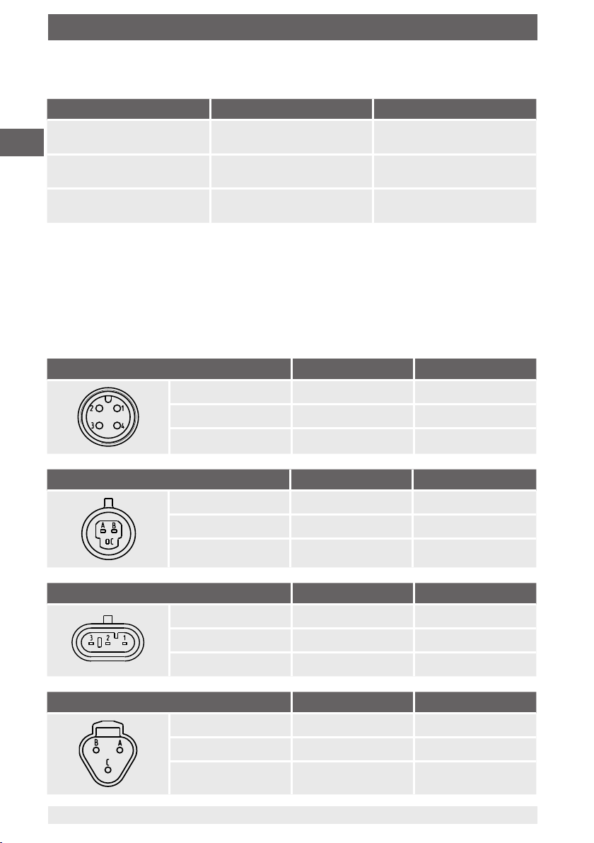
9.7 Electrical connections
Short-circuit resistance: S+ to U
-
Reverse polarity protection: U+ to U- (no reverse polarity protection with ratiometric
output signal)
Insulation voltage: DC 500 V
Connection diagrams
Circular connector M12 x 1 (4-pin) 2-wire 3-wire
U
+
U
-
S
+
1 1
3 3
- 4
-40 ... +85 °C
[-40 ... +185 °F]
-40 ... +85 °C
[-40 ... +185 °F]
-40 ... +85 °C
[-40 ... +185 °F]
Metri-Pack series 150 (3-pin) 2-wire 3-wire
U
+
U
-
S
+
B B
A A
- C
AMP Superseal 1.5 (3-pin) 2-wire 3-wire
U
+
U
-
S
+
3 3
1 1
- 2
Deutsch DT04-3P (3-pin) 2-wire 3-wire
18
U
+
U
-
S
+
WIKA operating instructions, OEM pressure sensor, model MH-3
A A
B B
- C
14136172.03 11/2019 EN/DE/FR/ES
Page 19

9. Specifications
Cable outlet 2-wire 3-wire
U
+
U
-
S
+
Wire cross-section 0.75 mm
2
(with end splices)
Cable diameter 6.6 mm
Cable length 0.5 m or 2 m
Legend
U
Positive power supply terminal
+
U-Negative power supply terminal
Analogue output
S
+
9.8 Process connections
brown brown
green green
- white
EN
Standard Thread
size
Max.
nominal
pressure
MH-3 MH-3-HY Sealing and temperature
2)
1)
range
Standard
Option (MH-3)
(MH-3)
EN 837 G ¼ B 600 bar
[8,000 psi]
DIN EN ISO 1179-2
(formerly DIN 3852-E)
DIN EN ISO 9974-2
(formerly DIN 3852-E)
ISO 6149-2 M14 x 1.5 600 bar
SAE J514 Fig.34B 7/16-20
ANSI/ASME B1.20.1 ¼ NPT 600 bar
1) Details must be tested separately in the respective application. The specified values for the max. nominal
pressure serve only as a rough orientation. The values depend on the temperature, the seals used, the selected torque, the type and the material of the mating thread and the prevailing operating conditions.
2) Model MH-3-HY is delivered without sealing. Depending on the process connection and measuring range,
including overload safety, an appropriate sealing has to be selected.
G ¼ A 600 bar
[8,000 psi]
M14 x 1.5 600 bar
[8,000 psi]
[8,000 psi]
600 bar
UNF-2A
[8,000 psi]
[8,000 psi]
x x Copper
-40 ... +125 °C
[-40 ... +257 °F]
x - NBR
-40 ... +100 °C
[-40 ... +212 °F]
x - - -
x - - -
x x - -
x x - -
Stainless steel
-40 ... +125 °C
[-40 ... +257 °F]
FPM/FKM
-40 ... +125 °C
[-40 ... +257 °F]
The sealings listed under “Standard” are included in the delivery (only for model MH-3).
14136172.03 11/2019 EN/DE/FR/ES
19WIKA operating instructions, OEM pressure sensor, model MH-3
Page 20
9. Specifications
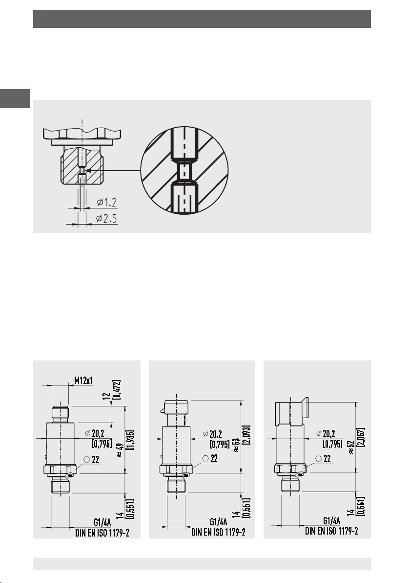
CDS system
All process connections are available with the CDS system.
The diameter of the pressure port is reduced in order to counteract pressure spikes and
cavitation (see fig.1).
EN
Illustration of the CDS system
9.9 Materials
Wetted parts
MH-3: Stainless steel
MH-3-HY: Stainless steel, 2.4711
Non-wetted parts
Highly resistant glass-fibre reinforced plastic (PBT)
9.10 Dimensions in mm
with M12 x 1 circular connector with Metri-Pack series 150 with Deutsch DT04-3P
20
WIKA operating instructions, OEM pressure sensor, model MH-3
14136172.03 11/2019 EN/DE/FR/ES
Page 21
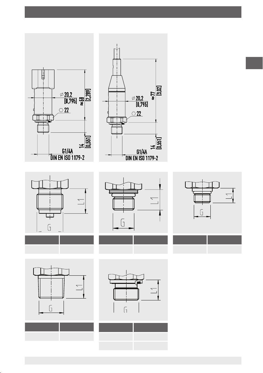
9. Specifications
with AMP Superseal 1.5
with cable outlet
EN
G L1
G ¼ B 13 [0.51]
G L1
¼ NPT 13 [0.51]
14136172.03 11/2019 EN/DE/FR/ES
G L1
M14 x 1.5 13.5 [0.53]
G L1
G ¼ A 14 [0.55]
M14 x 1.5 14 [0.55]
G L1
7/16-20 UNF 12 [0.47]
21WIKA operating instructions, OEM pressure sensor, model MH-3
Page 22
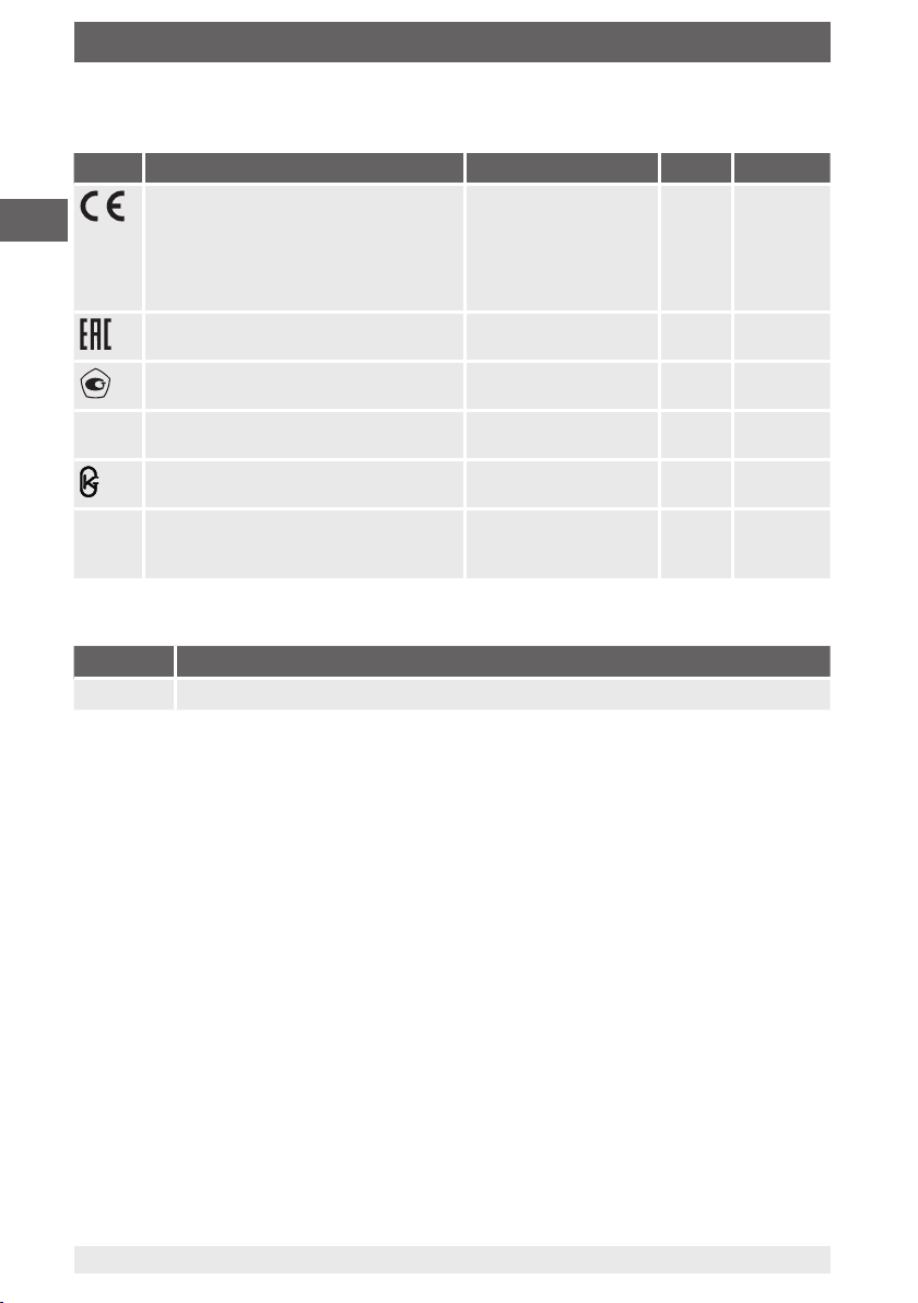
9. Specifications
9.11 Approvals
Logo Description Country MH-3 MH-3-HY
EU declaration of conformity
■
EN
-
-
EMC directive, EN 61326 emission
(group 1, class B) and immunity (industrial application)
■
Pressure equipment directive
■
RoHS directive
EAC
EMC directive
GOST
Metrology, measurement technology
MTSCHS
Permission for commissioning
MazInMetr
Metrology, measurement technology
EC79/2009
Type approval for hydrogen-powered
vehicles
Manufacturer‘s information and certificates
Logo Description
- MTTF: > 100 years (only applies to model MH-3)
European Union x x
Eurasian Economic
Community
Russia x -
Kazakhstan x -
Kazakhstan x -
European Union - x
x -
Approvals and certificates, see website
For information on tapped holes and welding sockets, see technical information
IN 00.14 at www.wika.com.
For special models MH-30000 other technical specifications apply. Please note the
specifications stated on the order confirmation and the delivery note.
For further specifications see WIKA data sheet PE 81.59 and the order documentation.
22
WIKA operating instructions, OEM pressure sensor, model MH-3
14136172.03 11/2019 EN/DE/FR/ES
Page 23

Inhalt
Inhalt
1. Allgemeines 24
2. Aufbau und Funktion 25
3. Sicherheit 26
4. Transport, Verpackung und Lagerung 28
5. Inbetriebnahme, Betrieb 29
6. Störungen 31
7. Wartung und Reinigung 32
8. Demontage, Rücksendung und Entsorgung 33
9. Technische Daten 35
Konformitätserklärungen finden Sie online unter www.wika.de
DE
14136172.03 11/2019 EN/DE/FR/ES
23WIKA Betriebsanleitung OEM-Drucksensor, Typ MH-3
Page 24

1. Allgemeines
1. Allgemeines
■
Das in der Betriebsanleitung beschriebene Gerät wird nach dem aktuellen Stand der
Technik konstruiert und gefertigt. Alle Komponenten unterliegen während der Fertigung strengen Qualitäts- und Umweltkriterien. Unsere Managementsysteme sind
DE
nach ISO 9001 und ISO 14001 zertifiziert.
■
Diese Betriebsanleitung gibt wichtige Hinweise zum Umgang mit dem Gerät. Voraussetzung für sicheres Arbeiten ist die Einhaltung aller angegebenen Sicherheitshinweise und Handlungsanweisungen.
■
Die für den Einsatzbereich des Gerätes geltenden örtlichen Unfallverhütungsvorschriften und allgemeinen Sicherheitsbestimmungen einhalten.
■
Die Betriebsanleitung ist Produktbestandteil und muss in unmittelbarer Nähe des
Gerätes für das Fachpersonal jederzeit zugänglich aufbewahrt werden. Betriebsanleitung an nachfolgende Benutzer oder Besitzer des Gerätes weitergeben.
■
Das Fachpersonal muss die Betriebsanleitung vor Beginn aller Arbeiten sorgfältig
durchgelesen und verstanden haben.
■
Es gelten die allgemeinen Geschäftsbedingungen in den Verkaufsunterlagen.
■
Technische Änderungen vorbehalten.
■
Weitere Informationen:
- Internet-Adresse: www.wika.de / www.wika.com
- Zugehöriges Datenblatt: PE 81.59
- Anwendungsberater:
Tel.: +49 9372 132-0
Fax: +49 9372 132-406
info@wika.com
24
WIKA Betriebsanleitung OEM-Drucksensor, Typ MH-3
14136172.03 11/2019 EN/DE/FR/ES
Page 25
2. Aufbau und Funktion
2. Aufbau und Funktion
2.1 Überblick
Elektrischer Anschluss (je nach Ausführung)
Gehäuse
Prozessanschluss, Schlüsselfläche
Prozessanschluss, Gewinde
2.2 Signalbegrenzung (nicht für MH-3-HY)
Das Ausgangssignal eines Drucksensors kann über dem nominellen maximalen Signalwert liegen, sofern keine Signalbegrenzung eingestellt ist. Ebenso kann das Ausgangssignal unter dem nominellen minimalen Signalwert liegen. Dieser undefinierte Zustand
kann einen Fehler in der Maschine (Software) des Kunden verursachen. Die Signalbegrenzung beschränkt das Ausgangssignal auf einen vom Kunden zu definierenden
Minimal- bzw. Maximalwert.
DE
2.3 Diagnosefunktion
Anhand des Ausgangssignales lassen sich Fehlerzustände erkennen und mittels
Software bewerten. Somit können permanente und temporäre Fehler unterschieden
werden.
2.4 CDS-System
Alle Prozessanschlüsse verfügen über das CDS-System. Der Durchmesser des Druckkanals ist verringert, um Druckspitzen und Kavitation entgegenzuwirken
2.5 Lieferumfang
■
Drucksensor
■
Betriebsanleitung (bei Typ MH-3-HY)
Lieferumfang mit dem Lieferschein abgleichen.
14136172.03 11/2019 EN/DE/FR/ES
25WIKA Betriebsanleitung OEM-Drucksensor, Typ MH-3
Page 26
3. Sicherheit
3. Sicherheit
3.1 Symbolerklärung
WARNUNG!
... weist auf eine möglicherweise gefährliche Situation hin, die zum Tod
DE
3.2 Bestimmungsgemäße Verwendung
Der Drucksensor dient der Messung von Druck. Der gemessene Druck wird als elektrisches Signal ausgegeben.
Der Drucksensor Typ MH-3 ist für den Einsatz in mobilen Arbeitsmaschinen bestimmt.
oder zu schweren Verletzungen führen kann, wenn sie nicht gemieden
wird.
VORSICHT!
... weist auf eine möglicherweise gefährliche Situation hin, die zu geringfügigen oder leichten Verletzungen bzw. Sach- und Umweltschäden
führen kann, wenn sie nicht gemieden wird.
Information
... hebt nützliche Tipps und Empfehlungen sowie Informationen für einen
effizienten und störungsfreien Betrieb hervor.
Der Drucksensor MH-3-HY für mobile Wasserstoffanwendungen dient üblicherweise zur
Überwachung des Tankdruckes und des Druckes nach dem Reduzierventil in wasserstoffbetriebenen Fahrzeugen, speziell Flurförderfahrzeugen, Nutz-/Kommunalfahrzeugen und Bussen. Die genaue Position des Sensors ist dabei Kunden- und Applikationsabhängig.
Den Drucksensor nur in Anwendungen verwenden, die innerhalb seiner technischen
Leistungsgrenzen liegen (z. B. max. Umgebungstemperatur, Materialverträglichkeit, ...).
→ Leistungsgrenzen siehe Kapitel 9 „Technische Daten“
Das Gerät ist ausschließlich für den hier beschriebenen bestimmungsgemäßen
Verwendungszweck konzipiert und konstruiert und darf nur dementsprechend verwendet werden.
Ansprüche jeglicher Art aufgrund von nicht bestimmungsgemäßer Verwendung sind
ausgeschlossen.
26
WIKA Betriebsanleitung OEM-Drucksensor, Typ MH-3
14136172.03 11/2019 EN/DE/FR/ES
Page 27

3. Sicherheit
Technische Einschränkungen
■
Ein dauerhafter Betrieb im Überlastbereich ist nicht zulässig. Oberhalb des Betriebsdruckes bis zur Überlastgrenze arbeitet der Drucksensor außerhalb seiner Spezifikation. Die Überlastgrenze ist dafür gedacht, dass der Drucksensor als Teil eines
Druckbehältersystems während der Druckfestigkeitsprüfung nicht beschädigt wird.
■
Die Überlastgrenze darf zu keinem Zeitpunkt überschritten werden, auch nicht beim
Auftreten von Fehlern in der Endanwendung. Belastungen oberhalb der Überlastgrenze können irreversible Schäden hervorrufen, die z. B. zu dauerhaften Messfehlern führen.
Besondere Hinweise aufgrund des Mediums Wasserstoff (Typ MH-3-HY)
Der angebotene Sensor verwendet die medienberührten Werkstoffe 2.4711 und 1.4404.
Diese Werkstoffe sind beständig gegen Wasserstoffversprödung.
Bei einer Temperatur von bis zu 30 °C beträgt die Stabilität unter Wasserstoffeinfluss
typisch 1 %/Jahr, maximal 3 %/Jahr.
Aufgrund von Wasserstoffdiffusion in die Sensorstrukturen kann es in Abhängigkeit der
Zeit zum Driften des Signals kommen. Die Zeitdauer bis zum Auftreten einer relevanten Signaldrift und die Größe der Signaldrift hängen hauptsächlich von Faktoren wie
der Temperatur des Wasserstoffs, dem Wasserstoffanteil im Messmedium sowie der
verwendeten Membranstärke des Drucksensors ab.
Es wird ausdrücklich empfohlen, dass der Anwender die ausgewählte Produktausführung in der/den vorgesehenen Applikation(en) mit den spezifizierten Umgebungsbedingungen auf Eignung testet.
DE
3.3 Personalqualifikation
Fachpersonal
Das vom Betreiber autorisierte Fachpersonal ist aufgrund seiner fachlichen Ausbildung,
seiner Kenntnisse der Mess- und Regelungstechnik und seiner Erfahrungen sowie
Kenntnis der landesspezifischen Vorschriften, geltenden Normen und Richtlinien in der
Lage, die beschriebenen Arbeiten auszuführen und mögliche Gefahren selbstständig zu
erkennen.
3.4 Persönliche Schutzausrüstung
Die persönliche Schutzausrüstung dient dazu, das Fachpersonal gegen Gefahren
zu schützen, die dessen Sicherheit oder Gesundheit bei der Arbeit beeinträchtigen
könnten. Beim Ausführen der verschiedenen Arbeiten an und mit dem Gerät muss das
Fachpersonal persönliche Schutzausrüstung tragen.
Im Arbeitsbereich angebrachte Hinweise zur persönlichen Schutzausrüstung
befolgen!
Die erforderliche persönliche Schutzausrüstung muss vom Betreiber zur Verfügung
gestellt werden.
14136172.03 11/2019 EN/DE/FR/ES
27WIKA Betriebsanleitung OEM-Drucksensor, Typ MH-3
Page 28

3. Sicherheit/ 4. Transport, Verpackung und Lagerung
5
3
2
3.5 Beschilderung, Sicherheitskennzeichnungen
Typenschilder
wika.com
DE
MH-3
1 Erzeugnis-Nr. 3 Kodiertes Herstelldatum
2 Serien-Nr. 4 Messbereich
1 Erzeugnis-Nr. 4 Technische Daten
2 Zulassungen 5 Kodiertes Herstelldatum
3 Nominal Working Pressure (NWP)
Nominal Working Pressure nach 79/2009/EG, entspricht Nennbetriebsdruck bei 15 °C
4. Transport, Verpackung und Lagerung
4.1 Transport
Drucksensor auf eventuell vorhandene Transportschäden untersuchen.
Offensichtliche Schäden unverzüglich mitteilen.
1
2
4
3
5
4.2 Verpackung und Lagerung
Verpackung erst unmittelbar vor der Montage entfernen.
Die Verpackung aufbewahren, denn diese bietet bei einem Transport einen optimalen
Schutz (z. B. wechselnder Einbauort, Reparatursendung).
Zulässige Bedingungen am Lagerort:
■
Lagertemperatur: siehe Kapitel 9 „Technische Daten“
■
Feuchtigkeit: 67 % relative Feuchte (keine Betauung)
Folgende Einflüsse vermeiden:
■
Direktes Sonnenlicht oder Nähe zu heißen Gegenständen
■
Mechanische Vibration, mechanischer Schock (hartes Aufstellen)
■
Ruß, Dampf, Staub und korrosive Gase
■
Explosionsgefährdete Umgebung, entzündliche Atmosphären
28
WIKA Betriebsanleitung OEM-Drucksensor, Typ MH-3
14136172.03 11/2019 EN/DE/FR/ES
Page 29

4. Transport, .../5. Inbetriebnahme, Betrieb
Das Gerät in der Originalverpackung an einem Ort lagern, der die oben gelisteten
Bedingungen erfüllt. Wenn die Originalverpackung nicht vorhanden ist, dann das Gerät
wie folgt verpacken und lagern:
1. Das Gerät in eine antistatische Plastikfolie einhüllen.
2. Das Gerät mit dem Dämmmaterial in der Verpackung platzieren.
3. Bei längerer Einlagerung (mehr als 30 Tage) einen Beutel mit Trocknungsmittel der
Verpackung beilegen.
5. Inbetriebnahme, Betrieb
5.1 Gerät montieren
Anforderungen an Montagestelle
Die Montagestelle muss folgende Bedingungen erfüllen:
■
Ausreichend Platz für eine sichere elektrische Installation.
■
Zulässige Umgebungs- und Messstofftemperaturen bleiben innerhalb der Leistungsgrenzen. Mögliche Einschränkungen des Umgebungstemperaturbereichs durch
verwendeten Gegenstecker berücksichtigen.
→ Leistungsgrenzen siehe Kapitel 9 „Technische Daten“
Abdichtungsvarianten
Zylindrische Gewinde
Dichtfläche mit Flachdichtung, Dichtlinse oder
WIKA-Profildichtung abdichten.
DE
Kegelige Gewinde
Gewinde mit Dichtwerkstoff umwickeln
(z. B. PTFE-Band).
Gerät montieren
Der max. Drehmoment ist abhängig von der Montagestelle (z. B.
Werkstoff und Form). Bei Fragen wenden Sie sich an unseren Anwendungsberater.
→ Kontaktdaten siehe Kapitel 1 „Allgemeines“ oder Rückseite der
Betriebsanleitung.
14136172.03 11/2019 EN/DE/FR/ES
nach EN 837
NPT, R und PT
nach ISO 1179-2
(ehemals DIN 3852-E)
29WIKA Betriebsanleitung OEM-Drucksensor, Typ MH-3
Page 30

5. Inbetriebnahme, Betrieb
1. Dichtfläche abdichten (→ siehe „Abdichtungsvarianten“).
.
Drucksensor handfest in Montagestelle einschrauben.
2
.
Mit Drehmomentschlüssel über Schlüsselfläche anziehen.
3
5.2 Gerät elektrisch anschließen
Anforderungen an Spannungsversorgung
DE
Hilfsenergie: siehe Kapitel 9 „Technische Daten“
Anforderungen an elektrische Verbindung
■
Kabeldurchmesser passt zur Kabeldurchführung des Gegensteckers.
■
Kabelverschraubung und Dichtungendes Gegensteckers sitzen korrekt.
■
Bei Kabelausgängen kann keine Feuchtigkeit am Kabelende eindringen.
Anforderung an Schirmung und Erdung
■
Den Drucksensor über den Prozessanschluss erden (Typ MH-3).
■
Der Anschluss erfolgt im Fahrzeug mit einer geeigneten, der Regelung 10 entsprechenden, Spannungsversorgung/Steuergerät (MH-3-HY).
■
Der Anschluss an Fahrzeug-Masse erfolgt über den Prozessanschluss (MH-3-HY).
Gemäß EN 61326-1 müssen bei Außeninstallationen Störungen durch Stoßspannungen berücksichtigt werden. Zum Schutz des Gerätes muss der Anschluss mit einem
geschirmten Kabel erfolgen. Der Schirm des Kabels muss auf mindestens einer Seite
mit Erde bzw. einem geeigneten Bezugspotential verbunden werden. Optional ist eine
geeignete externe Maßnahme zum Schutz vor Stoßspannungen vorzusehen.
Gerät anschließen
1. Gegenstecker oder Kabelausgang konfektionieren.
→ Siehe „Anschlussbelegungen“
.
2
Steckverbindung herstellen.
Anschlussbelegungen
Siehe Kapitel 9. „Technische Daten“.
30
WIKA Betriebsanleitung OEM-Drucksensor, Typ MH-3
14136172.03 11/2019 EN/DE/FR/ES
Page 31

6. Störungen
6. Störungen
VORSICHT!
Körperverletzungen, Sach- und Umweltschäden
Können Störungen mit Hilfe der aufgeführten Maßnahmen nicht beseitigt
werden, Drucksensor unverzüglich außer Betrieb setzen.
▶
Sicherstellen, dass kein Druck bzw. Signal mehr anliegt und gegen
versehentliche Inbetriebnahme schützen.
▶
Kontakt mit dem Hersteller aufnehmen.
▶
Bei notwendiger Rücksendung die Hinweise unter Kapitel 8.2
„Rücksendung“ beachten.
WARNUNG!
Körperverletzungen, Sach- und Umweltschäden durch gefährliche
Messstoffe
Bei Kontakt mit gefährlichen Messstoffen (z. B. Sauerstoff, Acetylen,
brennbaren oder giftigen Stoffen), gesundheitsgefährdenden Messstoffen (z. B. ätzend, giftig, krebserregend, radioaktiv) sowie bei Kälteanlagen, Kompressoren besteht die Gefahr von Körperverletzungen, Sachund Umweltschäden.
▶
Am Gerät können im Fehlerfall aggressive Messstoffe mit extremer
Temperatur und unter hohem Druck oder Vakuum anliegen.
▶
Bei diesen Messstoffen müssen über die gesamten allgemeinen
Regeln hinaus die einschlägigen Vorschriften beachtet werden.
▶
Notwendige Schutzausrüstung tragen (siehe Kapitel 3.4 „Persönliche
Schutzausrüstung“).
DE
Kontaktdaten siehe Kapitel 1 „Allgemeines“ oder Rückseite der Betriebsanleitung.
Störungen Ursachen Maßnahmen
Kunststoff ist ausgeblichen UV-Einstrahlung Keine Maßnahmen notwendig
Kein Ausgangssignal Leitungsbruch Durchgang überprüfen, ggf.
Keine/Falsche Hilfsenergie Hilfsenergie korrigieren
Kein/Falsches Ausgangssignal
Gleichbleibendes Ausgangssi-
gnal bei Druckänderung
14136172.03 11/2019 EN/DE/FR/ES
Verdrahtungsfehler Verdrahtung korrigieren
Mechanische Überlastung
durch Überdruck
Verfärbung ist unbedenklich
Leitung austauschen
Gerät austauschen, bei
wiederholtem Ausfall Kontakt
mit dem Hersteller aufnehmen.
31WIKA Betriebsanleitung OEM-Drucksensor, Typ MH-3
Page 32

6. Störungen/7. Wartung und Reinigung
Störungen Ursachen Maßnahmen
Signalspanne zu klein/fällt ab Mechanische Überlastung
durch Überdruck
Membranbeschädigung, z. B.
durch Schläge, abrasives/
DE
Signalspanne schwankend/
ungenau
Abweichendes Nullpunktsignal Zu hohe/niedrige Einsatztem-
aggressives Medium; Korrosion an Membran oder Prozessanschluss; Übertragungsmedium fehlt
Dichtung/Dichtfläche beschädigt oder verschmutzt,
Dichtung sitzt nicht korrekt,
Gewindegänge verkantet
EMV-Störquellen in Umgebung,
z. B. Frequenzumrichter
Zu hohe/niedrige Einsatztemperaturen
Gerät nicht geerdet Gerät erden
Stark schwankender Druck des
Prozessmediums
peraturen
Abweichende Einbaulage Nullpunkt korrigieren
Überlast-Druckgrenze
überschritten
Im unberechtigten Reklamationsfall berechnen wir die Reklamationsbearbeitungskosten.
Gerät austauschen, bei wiederholtem Ausfall Kontakt mit dem
Hersteller aufnehmen.
Gerät austauschen, bei
wiederholtem Ausfall Kontakt
mit dem Hersteller aufnehmen.
Dichtung/Dichtfläche säubern,
ggf. Dichtung austauschen
Gerät abschirmen; Leitungsabschirmung; Störquelle entfernen
Temperatur senken/erhöhen
Dämpfung; Beratung durch
Hersteller
Temperatur senken/erhöhen
Druck reduzieren
7. Wartung und Reinigung
7.1 Wartung
Dieser Drucksensor ist wartungsfrei.
Reparaturen sind ausschließlich vom Hersteller durchzuführen.
Regelmäßige Kontrolle der Dichtung durch den Betreiber notwendig.
32
WIKA Betriebsanleitung OEM-Drucksensor, Typ MH-3
14136172.03 11/2019 EN/DE/FR/ES
Page 33

7. .../8. Demontage, Rücksendung und Entsorgung
7.2 Reinigung
VORSICHT!
Ungeeignete Reinigungsmittel
Eine Reinigung mit ungeeigneten Reinigungsmitteln kann Gerät und
Typenschild beschädigen.
▶
Keine aggressiven Reinigungsmittel verwenden.
▶
Keine harten oder spitzen Gegenstände verwenden.
▶
Keine scheuernden Tücher oder Schwämme verwenden.
Geeignete Reinigungsmittel
■
Wasser
■
Handelsüblicher Geschirrreiniger
Gerät reinigen
▶
Geräteoberfläche mit weichem, feuchten Tuch abwischen.
8. Demontage, Rücksendung und Entsorgung
8.1 Demontage
WARNUNG!
Körperverletzungen, Sach- und Umweltschäden durch gefährliche
Messstoffe
Bei Kontakt mit gefährlichen Messstoffen (z. B. Sauerstoff, Acetylen,
brennbaren oder giftigen Stoffen), gesundheitsgefährdenden Messstoffen (z. B. ätzend, giftig, krebserregend, radioaktiv) sowie bei Kälteanlagen, Kompressoren besteht die Gefahr von Körperverletzungen, Sachund Umweltschäden.
▶
Am Gerät können im Fehlerfall aggressive Messstoffe mit extremer
Temperatur und unter hohem Druck oder Vakuum anliegen.
▶
Notwendige Schutzausrüstung tragen (siehe Kapitel 3.4 „Persönliche
Schutzausrüstung“).
DE
Gerät demontieren
1. Gerät stromlos schalten.
.
2
Elektrische Verbindung trennen.
.
Gerät mit Schraubenschlüssel über Schlüsselfläche ausschrauben.
3
14136172.03 11/2019 EN/DE/FR/ES
33WIKA Betriebsanleitung OEM-Drucksensor, Typ MH-3
Page 34

8. Demontage, Rücksendung und Entsorgung
8.2 Rücksendung
Beim Versand des Gerätes unbedingt beachten:
Alle an WIKA gelieferten Geräte müssen frei von Gefahrstoffen (Säuren, Laugen,
Lösungen, etc.) sein und sind daher vor der Rücksendung zu reinigen.
DE
Zur Rücksendung des Gerätes die Originalverpackung oder eine geeignete Transportverpackung verwenden.
8.3 Entsorgung
Durch falsche Entsorgung können Gefahren für die Umwelt entstehen.
Gerätekomponenten und Verpackungsmaterialien entsprechend den landesspezifischen Abfallbehandlungs- und Entsorgungsvorschriften umweltgerecht entsorgen.
WARNUNG!
Körperverletzungen, Sach- und Umweltschäden durch
Messstoffreste
Messstoffreste im ausgebauten Gerät können zur Gefährdung von Personen, Umwelt und Einrichtung führen.
▶
Bei Gefahrenstoffen das Sicherheitsdatenblatt für den entsprechenden Messstoff beilegen.
▶
Gerät reinigen, siehe Kapitel 7.2 „Reinigung“.
Hinweise zur Rücksendung befinden sich in der Rubrik „Service“ auf
unserer lokalen Internetseite.
Nicht mit dem Hausmüll entsorgen. Für eine geordnete Entsorgung
gemäß nationaler Vorgaben sorgen.
34
WIKA Betriebsanleitung OEM-Drucksensor, Typ MH-3
14136172.03 11/2019 EN/DE/FR/ES
Page 35

9. Technische Daten
9. Technische Daten
9.1 Messbereiche
Relativdruck MH-3 MH-3-HY
bar 0 ... 6 x -
0 ... 10 x 0 ... 16 x 0 ... 20 - x
0 ... 25 x x
0 ... 40 x x
0 ... 60 x x
0 ... 100 x x
0 ... 160 x x
0 ... 250 x x
0 ... 400 x x
0 ... 600 x x
psi 0 … 100 x -
0 … 160 x 0 … 200 x 0 ... 300 x x
0 ... 500 x x
0 ... 1.000 x x
0 ... 1.500 x x
0 ... 2.000 x x
0 ... 3.000 x x
0 ... 5.000 x x
0 ... 8.000 x x
MPa (1 bar = 0,1 MPa)
DE
Überlastsicherheit: 2-fach (für einzelne psi-Messbereiche bei Typ MH-3-HY abweichend)
Vakuumfestigkeit: Ja
9.2 Ausgangssignale
Signalart Signal MH-3 MH-3-HY
Strom (2-Leiter) 4 ... 20 mA x x
Spannung (3-Leiter) DC 0 ... 10 V x -
DC 1 ... 5 V x DC 1 ... 6 V x -
Ratiometrisch DC 0,5 ... 4,5 V x x
14136172.03 11/2019 EN/DE/FR/ES
35WIKA Betriebsanleitung OEM-Drucksensor, Typ MH-3
Page 36

9. Technische Daten
Bürde
■
4 ... 20 mA: ≤ (Hilfsenergie - 10 V)/0,02 A
■
DC 0 ... 10 V: > 5 kΩ
■
DC 1 ... 5 V: > 2,5 kΩ
■
DC 1 ... 6 V: > 5 kΩ
■
DC 0,5 ... 4,5 V: > 4,5 kΩ
DE
9.3 Spannungsversorgung
Hilfsenergie
Die Hilfsenergie ist abhängig vom gewählten Ausgangssignal.
■
4 ... 20 mA: DC 10 ... 36 V
■
DC 0 ... 10 V: DC 14 ... 36 V
■
DC 1 ... 5 V: DC 8 ... 36 V
■
DC 1 ... 6 V: DC 9 ... 36 V
■
DC 0,5 ... 4,5 V: DC 4,5 ... 5,5 V
Stromaufnahme
Die Stromaufnahme ist abhängig vom gewählten Ausgangssignal.
■
4 ... 20 mA < 30 mA
■
DC 0 ... 10 V < 10 mA
■
DC 1 ... 5 V < 10 mA
■
DC 1 ... 6 V < 10 mA
■
DC 0,5 ... 4,5 V < 10 mA
9.4 Referenzbedingungen (nach IEC 61298-1)
Temperatur: 15 ... 25 °C [59 ... 77 °F]
Luftdruck: 860 ... 1.060 mbar [12,5 ... 15,4 psi]
Luftfeuchte: 45 ... 75 % r. F.
Hilfsenergie: DC 24 V
Einbaulage: Kalibriert bei senkrechter Einbaulage mit dem Prozessanschluss nach
unten.
9.5 Genauigkeitsangaben
Genauigkeit bei Referenzbedingungen
≤ ±1 % der Spanne für Messbereiche ≥ 40 bar [≥ 500 psi]
≤ ±2 % der Spanne für Messbereiche < 40 bar [< 500 psi]
Einschließlich Nichtlinearität, Hysterese, Nullpunkt- und Endwertabweichung (entspricht
Messabweichung nach IEC 61298-2).
Nichtlinearität (nach IEC 61298-2)
≤ ±0,25 % der Spanne für Messbereiche ≥ 40 bar [≥ 500 psi]
≤ ±0,40 % der Spanne für Messbereiche < 40 bar [< 500 psi]
36
WIKA Betriebsanleitung OEM-Drucksensor, Typ MH-3
14136172.03 11/2019 EN/DE/FR/ES
Page 37

9. Technische Daten
Temperaturfehler bei -40 ... +100 °C [-40 ... +212 °F]
Mittlerer Temperaturkoeffizient Nullpunkt:
≤ ±0,15 % der Spanne/10 K für Messbereiche ≥ 40 bar [≥ 500 psi]
Für Messbereiche < 40 bar [< 500 psi]: Auf Anfrage
Mittlerer Temperaturkoeffizient Spanne: ≤ ±0,08 % der Spanne/10 K
Einschwingzeit
≤ 2 ms
Langzeitstabilität
≤ ±0,2 % der Spanne/Jahr für Messbereiche ≥ 40 bar [≥ 500 psi]
≤ ±0,3 % der Spanne/Jahr für Messbereiche < 40 bar
[< 500 psi]
Bei Typ MH-3-HY:
Messstofftemperaturbereich -40 ... +30 °C [-40 ... +86 °F]:
typ. ≤ ±1 %/max. ≤ ±3 % der Spanne/Jahr
Es wird ausdrücklich empfohlen, dass der Anwender die ausgewählte Produktausführung in der/den vorgesehenen Applikation(en) mit den spezifizierten Umgebungsbedingungen auf Eignung testet.
9.6 Einsatzbedingungen
Schutzarten (nach IEC 60529)
Die Schutzart ist abhängig vom Typ des elektrischen Anschlusses.
Elektrischer Anschluss Schutzart
Deutsch DT04-3P (3-polig) IP67 x
Delphi Stecker Metri-Pack Serie 150,
3-polig
Rundstecker M12 x 1 (4-polig) IP67 x
AMP Superseal Stecker 1.5, 3-polig IP67 x x
Kabelausgang (0,5/1/2,5 m), 2-polig IP6K9K x
Kabelausgang (0,5/1/2,5 m), 3-polig IP6K9K x
1) Die angegebenen Schutzarten gelten nur im gesteckten Zustand mit Gegensteckern entsprechender Schutzart.
IP67 x x
1)
MH-3 MH-3-HY
DE
Vibrationsbeständigkeit
20 g (nach IEC 60068-2-6)
Schockfestigkeit
500 g (nach IEC 60068-2-27)
Zulässige Temperaturbereiche
14136172.03 11/2019 EN/DE/FR/ES
37WIKA Betriebsanleitung OEM-Drucksensor, Typ MH-3
Page 38

9. Technische Daten
MH-3 MH-3-HY
Umgebung -40 ... +100 °C
[-40 ... +212 °F]
Messstoff -40 ... +125 °C
[-40 ... +257 °F]
Lagerung -40 ... +100 °C
DE
[-40 ... +212 °F]
9.7 Elektrische Anschlüsse
Kurzschlussfestigkeit: S+ gegen U
-
Verpolungssschutz: U+ gegen U- (kein Verpolschutz bei ratiometrischem Ausgangssignal)
Isolationsspannung: DC 500 V
Anschlussschemen
Rundstecker M12 x 1 (4-polig) 2-Leiter 3-Leiter
U
+
U
-
S
+
1 1
3 3
- 4
-40 ... + 85 °C
[-40 ... +185 °F]
-40 ... + 85 °C
[-40 ... +185 °F]
-40 ... + 85 °C
[-40 ... +185 °F]
Metri-Pack Serie 150 (3-polig) 2-Leiter 3-Leiter
U
+
U
-
S
+
B B
A A
- C
AMP Superseal 1,5 (3-polig) 2-Leiter 3-Leiter
U
+
U
-
S
+
3 3
1 1
- 2
Deutsch DT04-3P (3-polig) 2-Leiter 3-Leiter
38
U
+
U
-
S
+
A A
B B
- C
WIKA Betriebsanleitung OEM-Drucksensor, Typ MH-3
14136172.03 11/2019 EN/DE/FR/ES
Page 39

9. Technische Daten
Kabelausgang 2-Leiter 3-Leiter
U
+
U
-
S
+
Aderquerschnitt 0,75 mm
2
(mit Aderendhülsen)
Kabeldurchmesser 6,6 mm
Kabellänge 0,5 m oder 2 m
Legende
U
Positiver Versorgungsanschluss
+
U-Negativer Versorgungsanschluss
Analogausgang
S
+
9.8 Prozessanschlüsse
braun braun
grün grün
- weiß
DE
Norm Gewinde-
größe
EN 837 G ¼ B 600 bar
DIN EN ISO 1179-2
(ehemals DIN 3852-E)
DIN EN ISO 9974-2
(ehemals DIN 3852-E)
ISO 6149-2 M14 x 1,5 600 bar
SAE J514 Fig.34B 7/16-20
ANSI/ASME B1.20.1 ¼ NPT 600 bar
1) Details sind in der jeweiligen Anwendung separat zu prüfen. Die angegebenen Werte für den max. Nenndruck
dienen nur zur groben Orientierung. Die Werte hängen von der Temperatur, der verwendeten Dichtung, dem
gewählten Drehmoment, der Art und dem Material des Gegengewindes und den vorherrschenden Betriebsbedingungen ab.
2) Typ MH-3-HY wird ohne Dichtung geliefert. Je nach Prozessanschluss und Messbereich, inklusive der Überlastsicherheit, muss eine entsprechende Dichtung gewählt werden.
G ¼ A 600 bar
M14 x 1,5 600 bar
UNF-2A
Max. Nenn-
1)
druck
[8.000 psi]
[8.000 psi]
[8.000 psi]
[8.000 psi]
600 bar
[8.000 psi]
[8.000 psi]
MH-3 MH-3-HY Dichtung und Temperatur-
bereich
Standard
(MH-3)
x x Kupfer
-40 ... +125 °C
[-40 ... +257 °F]
x - NBR
-40 ... +100 °C
[-40 ... +212 °F]
x - - -
x - - -
x x - -
x x - -
2)
Option
(MH-3)
CrNi-Stahl
-40 ... +125 °C
[-40 ... +257 °F]
FPM/FKM
-40 ... +125 °C
[-40 ... 257 °F]
Die unter „Standard“ aufgelisten Dichtungen sind im Lieferumfang enthalten (nur für
Typ MH-3).
14136172.03 11/2019 EN/DE/FR/ES
39WIKA Betriebsanleitung OEM-Drucksensor, Typ MH-3
Page 40

9. Technische Daten
CDS-System
Alle Prozessanschlüsse verfügen über das CDS-System.
Der Durchmesser des Druckkanals ist verringert, um Druckspitzen und Kavitation
entgegenzuwirken (siehe Abb.1).
Darstellung des CDS-Systems
DE
9.9 Werkstoffe
Messstoffberührte Teile
MH-3: CrNi-Stahl
MH-3-HY: CrNi-Stahl, 2.4711
Nicht messstoffberührte Teile
Hochbeständiger, glasfaserverstärkter Kunststoff (PBT)
9.10 Abmessungen in mm
mit Rundstecker M12 x 1 mit Metri-Pack Serie 150 mit Deutsch DT04-3P
40
WIKA Betriebsanleitung OEM-Drucksensor, Typ MH-3
14136172.03 11/2019 EN/DE/FR/ES
Page 41

9. Technische Daten
mit AMP Superseal 1,5
mit Kabelausgang
DE
G L1
G ¼ B 13 [0,51]
G L1
¼ NPT 13 [0,51]
14136172.03 11/2019 EN/DE/FR/ES
G L1
M14 x 1,5 13,5 [0,53]
G L1
G ¼ A 14 [0,55]
M14 x 1,5 14 [0,55]
G L1
7/16-20 UNF 12 [0,47]
41WIKA Betriebsanleitung OEM-Drucksensor, Typ MH-3
Page 42

9. Technische Daten
9.11 Zulassungen
Logo Beschreibung Land MH-3 MH-3-HY
EU-Konformitätserklärung
■
EMV-Richtlinie, EN 61326 Emission
(Gruppe 1, Klasse B) und Störfestigkeit
(industrieller Bereich)
■
DE
-
-
Druckgeräterichtlinie
■
RoHS-Richtlinie
EAC
EMV-Richtlinie
GOST
Metrologie, Messtechnik
MTSCHS
Genehmigung zur Inbetriebnahme
MazInMetr
Metrologie, Messtechnik
EC79/2009
Typgenehmigung für wasserstoffbetriebene
Kraftfahrzeuge
Herstellerinformationen und Bescheinigungen
Logo Beschreibung
- MTTF: > 100 Jahre (gilt nur für Typ MH-3)
Europäische Union x x
Eurasiche
Wirtschaftsgmeinschaft
Russland x -
Kasachstan x -
Kasachstan x -
Europäische Union - x
x -
Zulassungen und Zertifikate siehe Internetseite
Angaben zu Einschraublöchern und Einschweißstutzen siehe Technische Information
IN 00.14 unter www.wika.de.
Bei Sondertypen MH-30000 gelten abweichende technische Spezifikationen. Spezifikationen gemäß Auftragsbestätigung und Lieferschein beachten.
Weitere technische Daten siehe WIKA-Datenblatt PE 81.59 und Bestellunterlagen.
42
WIKA Betriebsanleitung OEM-Drucksensor, Typ MH-3
14136172.03 11/2019 EN/DE/FR/ES
Page 43

Sommaire
Sommaire
1. Généralités 44
2. Conception et fonction 45
3. Sécurité 46
4. Transport, emballage et stockage 48
5. Mise en service, utilisation 49
6. Dysfonctionnements 51
7. Entretien et nettoyage 53
8. Démontage, retour et mise au rebut 53
9. Spécifications 55
Déclarations de conformité disponibles en ligne sur www.wika.com
FR
14136172.03 11/2019 EN/DE/FR/ES
43Mode d'emploi WIKA, capteur de pression OEM, type MH-3
Page 44

1. Généralités
1. Généralités
■
L'instrument décrit dans le mode d'emploi est conçu et fabriqué selon les dernières
technologies en vigueur. Tous les composants sont soumis à des exigences environnementales et de qualité strictes durant la fabrication. Nos systèmes de gestion sont
certifiés selon ISO 9001 et ISO 14001.
■
FR
Ce mode d'emploi donne des indications importantes concernant l'utilisation de l'instrument. Il est possible de travailler en toute sécurité avec ce produit en respectant
toutes les consignes de sécurité et d'utilisation.
■
Respecter les prescriptions locales de prévention contre les accidents et les
prescriptions générales de sécurité en vigueur pour le domaine d'application de
l'instrument.
■
Le mode d'emploi fait partie de l'instrument et doit être conservé à proximité
immédiate de l'instrument et accessible à tout moment pour le personnel qualifié.
Confier le mode d'emploi à l'utilisateur ou propriétaire ultérieur de l'instrument.
■
Le personnel qualifié doit, avant de commencer toute opération, avoir lu soigneusement et compris le mode d'emploi.
■
Les conditions générales de vente mentionnées dans les documents de vente
s'appliquent.
■
Sous réserve de modifications techniques.
■
Pour obtenir d'autres informations :
- Consulter notre site Internet : www.wika.fr
- Fiche technique correspondante : PE 81.59
- Conseiller applications :
Tél. : +33 1 787049-46
Fax : +33 1 343084-94
info@wika.fr
44
Mode d'emploi WIKA, capteur de pression OEM, type MH-3
14136172.03 11/2019 EN/DE/FR/ES
Page 45

2. Conception et fonction
2. Conception et fonction
2.1 Vue générale
Raccordement électrique (en fonction de la version)
Boîtier
Raccord process, six pans
Raccord process, filetage
2.2 Limitation de signal (pas pour MH-3-HY)
Le signal de sortie d'un capteur de pression peut se trouver au-dessus de la valeur
de signal maximum nominale si aucune limitation de signal n'a été réglée. De même,
le signal de sortie peut aussi se trouver en-dessous de la valeur de signal minimum
nominale. Cette condition indéfinie peut causer une erreur dans la machine (logiciel)
du client. La limitation de signal limite le signal de sortie à une valeur minimum ou
maximum qui peut être définie par le client.
2.3 Fonction de diagnostic
Au moyen du signal de sortie, des conditions défectueuses peuvent être détectées
et évaluées par un logiciel. Il est ainsi possible de faire la différence entre des défauts
permanents et des défauts temporaires.
2.4 Système CDS
Tous les raccords process sont disponibles avec le système CDS. Le diamètre du canal
de pression est réduit afin de contrer les pics de pression et la cavitation.
2.5 Détail de la livraison
■
Capteur de pression
■
Mode d'emploi (pour le type MH-3-HY)
FR
Comparer le détail de la livraison avec le bordereau de livraison.
14136172.03 11/2019 EN/DE/FR/ES
45Mode d'emploi WIKA, capteur de pression OEM, type MH-3
Page 46

3. Sécurité
3. Sécurité
3.1 Explication des symboles
AVERTISSEMENT !
… indique une situation présentant des risques susceptibles de provoquer la mort ou des blessures graves si elle n'est pas évitée.
ATTENTION !
FR
3.2 Utilisation conforme à l'usage prévu
Le capteur de pression est utilisé pour mesurer la pression. La pression mesurée est
émise sous forme de signal électrique.
… indique une situation potentiellement dangereuse et susceptible de
provoquer de légères blessures ou des dommages matériels et pour
l'environnement si elle n'est pas évitée.
Information
... met en exergue les conseils et recommandations utiles de même que
les informations permettant d'assurer un fonctionnement efficace et
normal.
Le capteur de pression type MH-3 est prévu pour être utilisé dans des engins mobiles.
Le capteur de pression MH-3-HY pour des applications d'hydrogène mobiles est
utilisé typiquement pour la surveillance de la pression de cuves et la pression après
la soupape de réduction dans des véhicules fonctionnant à l'hydrogène, en particulier
des camions industriels, des véhicules utilitaires ou municipaux et des bus. La position
exacte du capteur dépend donc du client et de l'application.
Utiliser l'instrument analytique uniquement dans des applications qui se trouvent
dans les limites de ses performances techniques (par exemple température ambiante
maximale, étendues de mesure, ...).
→ Pour limites de performance voir chapitre 9 “Spécifications”.
Ces instruments sont conçus et construits exclusivement pour une utilisation conforme
à l'usage prévu décrit ici, et ne doivent être utilisés qu'à cet effet.
Aucune réclamation ne peut être recevable en cas d'utilisation non conforme à l'usage
prévu.
46
Mode d'emploi WIKA, capteur de pression OEM, type MH-3
14136172.03 11/2019 EN/DE/FR/ES
Page 47

3. Sécurité
Restrictions techniques
■
Toute opération permanente dans la plage de surpression est interdite. Au-dessus
de la pression de service, jusqu'à la limite de surpression, le capteur de pression
fonctionne en-dehors de sa spécification. La limite de surpression a pour but d'éviter
des dommages au capteur de pression, en tant que système sous pression, lors du
test de résistance à la pression.
■
Il ne faut jamais excéder la limite de surpression, même si des pannes se produisent
dans l'application finale. Les pressions supérieures à la limite de surpression peuvent
provoquer des dommages irréversibles pouvant conduire, par exemple, à des écarts
de mesure permanents.
Notes spécifiques basées sur le fluide hydrogène (type MH-3-HY)
Le capteur proposé utilise les matériaux en contact avec le fluide 2.4711 and 1.4404.
Ces matériaux sont résistants à la fragilisation due à l'hydrogène.
Avec une température allant jusqu'à 30 °C, la stabilité sous l'influence de l'hydrogène
est typiquement de 1 %/an, au maximum de 3 %/an.
En raison de la diffusion d'hydrogène dans les structures du capteur, une dérive de
signal peut se produire en fonction de la durée. La durée jusqu'à ce qu'une dérive de
signal importante se produise et la taille de la dérive de signal dépendent principalement de facteurs tels que la température de l'hydrogène, la teneur en hydrogène dans le
fluide et l'épaisseur de la membrane du capteur de pression utilisé.
Il est explicitement recommandé à l'utilisateur de tester la version de produit choisie
pour vérifier si elle convient à la ou les application(s) prévues dans les conditions
ambiantes spécifiées.
FR
3.3 Qualification du personnel
Personnel qualifié
Le personnel qualifié, autorisé par l'opérateur, est, en raison de sa formation spécialisée, de ses connaissances dans le domaine de l'instrumentation de mesure et de
régulation et de son expérience, de même que de sa connaissance des réglementations nationales et des normes en vigueur, en mesure d'effectuer les travaux décrits et
d'identifier de façon autonome les dangers potentiels.
3.4 Equipement de protection individuelle
L'équipement de protection individuelle sert à protéger le personnel qualifié contre
les dangers pouvant entraver la sécurité et la santé de ce dernier durant le travail. Le
personnel qualifié doit porter l'équipement de protection individuelle lors de l'exécution
des différents travaux sur et avec l'instrument.
Respecter les indications concernant l'équipement de protection individuelle
dans la zone de travail !
L'équipement de protection individuelle requis doit être mis à disposition par l'utilisateur.
14136172.03 11/2019 EN/DE/FR/ES
47Mode d'emploi WIKA, capteur de pression OEM, type MH-3
Page 48

3. Sécurité/4. Transport, emballage et stockage
3.5 Etiquetage, marquages de sécurité
Plaques signalétiques
wika.com
1
2
FR
1 N° Produit 3 Date de fabrication codée
2 Numéro de série 4 Etendue de mesure
1 N° Produit 4 Spécifications
2 Agréments 5 Date de fabrication codée
3 Pression de service nominale (NWP)
La pression de service nominale selon 79/2009/CE correspond à une pression de service nominale
à 15 °C
MH-3
4
4. Transport, emballage et stockage
4.1 Transport
Vérifier s'il existe des dégâts sur le capteur de pression qui pourraient être liés au transport.
Communiquer immédiatement les dégâts constatés.
3
5
4.2 Emballage et stockage
N'enlever l'emballage qu'avant le montage.
Conserver l'emballage, celui-ci offre, lors d'un transport, une protection optimale (par ex.
changement de lieu d'utilisation, renvoi pour réparation).
Conditions admissibles sur le lieu de stockage :
■
Température de stockage, voir chapitre 9 “Spécifications”
■
Humidité : 67 % d'humidité relative (sans condensation)
48
Mode d'emploi WIKA, capteur de pression OEM, type MH-3
14136172.03 11/2019 EN/DE/FR/ES
Page 49

4. Transport, .../5. Mise en service, exploitation
Eviter les influences suivantes :
■
Lumière solaire directe ou proximité d'objets chauds
■
Vibrations mécaniques, chocs mécaniques (mouvements brusques en le posant)
■
Suie, vapeur, poussière et gaz corrosifs
■
Environnements dangereux, atmosphères inflammables
Conserver l'instrument dans l'emballage original dans un endroit qui satisfait aux conditions susmentionnées. Si l'emballage d'origine n'est pas disponible, emballer et stocker
l'instrument comme suit :
1. Emballer l'instrument dans une feuille de plastique antistatique.
2. Placer l'instrument avec le matériau isolant dans l'emballage.
3. En cas de stockage prolongé (plus de 30 jours), mettre également un sachet absor-
beur d'humidité dans l'emballage.
5. Mise en service, utilisation
5.1 Montage de l'instrument
Exigences concernant le lieu d'installation
Le lieu d'installation doit remplir les conditions suivantes :
■
Un espace suffisant pour une installation électrique en toute sécurité.
■
Les températures ambiantes et du fluide admissibles restent dans les limites de
leurs performances. Considérer les restrictions possibles sur la plage de température
ambiante en fonction du contre-connecteur utilisé.
→ Pour les limites de performance voir chapitre 9 “Spécifications”
FR
Variantes de joint d'étanchéité
Filetage parallèle
Sceller la surface d'étanchéité avec un joint
d'étanchéité plat, une bague d'étanchéité de type
lentille ou un joint d'étanchéité profilé WIKA.
Filetages coniques
Envelopper les filetages avec du matériau
d'étanchéité (par exemple du ruban PTFE).
14136172.03 11/2019 EN/DE/FR/ES
selon EN 837
NPT, R et PT
selon ISO1179-2
(autrefois DIN 3852-E)
49Mode d'emploi WIKA, capteur de pression OEM, type MH-3
Page 50

5. Mise en service, utilisation
Montage de l'instrument
Le couple maximum dépend du point d'installation (par exemple matériau
et forme). Si vous avez des questions, veuillez contacter notre conseiller
applications.
→ Pour le détail des contacts voir le chapitre 1 “Généralités” ou au dos du
mode d'emploi.
1. Sceller la surface d'étanchéité (→ voir “Variantes de joints d'étanchéité”).
FR
.
2
A l'endroit d'installation, visser le capteur de pression en serrant à la main.
.
Serrer avec une clé dynamométrique en utilisant une clé plate
3
5.2 Connexion de l'instrument au système électrique
Exigences concernant la tension d'alimentation
Tension d'alimentation, voir chapitre 9 “Spécifications”.
Exigences concernant le raccordement électrique
■
Le diamètre du câble correspond au passe-câble du contre-connecteur.
■
Le presse-étoupe et les joints d'étanchéité du contre-connecteur sont posés correctement.
■
Avec les sorties câble, aucune humidité ne peut pénétrer à l'extrémité du câble.
Exigences concernant le blindage et la mise à la terre
■
Le capteur de pression doit être mis à la terre à l'aide du raccord process (type
MH-3).
■
Le raccordement est effectué dans le véhicule avec une alimentation électrique ou
une unité de commande conforme à la réglementation 10. (MH-3-HY).
■
Le raccordement à la masse du véhicule est effectué via le raccord process
(MH-3-HY).
En accord avec EN 61326-1, dans le cas d'installations situées à l'extérieur, des
défaillances causées par des surtensions doivent être prises en compte. Pour protéger
l'instrument, il faut le raccorder au moyen d'un câble blindé. Le blindage du câble doit
être connecté sur au moins un côté à la terre ou à un potentiel de référence adéquat. En
option, une mesure externe adéquate peut être prise pour assurer la protection contre
les surtensions.
Connexion de l'instrument
1. Assembler le contre-connecteur ou la sortie câble.
→ Voir “Configurations du raccordement”
.
2
Etablir la connexion.
Configurations du raccordement
Voir chapitre 9 “Spécifications”.
50
Mode d'emploi WIKA, capteur de pression OEM, type MH-3
14136172.03 11/2019 EN/DE/FR/ES
Page 51

6. Dysfonctionnements
6. Dysfonctionnements
ATTENTION !
Blessures physiques, dommages aux équipements et à l'environnement
Si des pannes ne peuvent être éliminées au moyen des mesures ici
énumérées, le capteur de pression doit être immédiatement mis hors
service
▶
S'assurer que la pression ou le signal n'est plus présent et protéger
contre une mise en service accidentelle.
▶
Contacter le fabricant.
▶
S'il est nécessaire de retourner l'instrument au fabricant, respecter les
indications mentionnées au chapitre 8.2 “Retour”.
AVERTISSEMENT !
Blessures physiques et dommages aux équipements et à l'environnement causés par un fluide dangereux
Lors du contact avec un fluide dangereux (par ex. oxygène, acétylène,
substances inflammables ou toxiques), un fluide nocif (par ex. corrosif,
toxique, cancérigène, radioactif), et également avec des installations
de réfrigération et des compresseurs, il y a un danger de blessures
physiques et de dommages aux équipements et à l'environnement.
▶
En cas d'erreur, des fluides agressifs peuvent être présents à une
température extrême et sous une pression élevée ou sous vide au
niveau de l'instrument.
▶
Pour ces fluides, les codes et directives appropriés existants doivent
être observés en plus des régulations standard.
▶
Porter les équipements de protection requis (voir chapitre 3.4 “Equipement de protection individuelle”).
FR
Pour le détail des contacts voir le chapitre 1 “Généralités” ou au dos du
mode d'emploi.
Dysfonctionnements Raisons Mesures
Le plastique se décolore Irradiation UV Pas de mesure requise
La décoloration n'a aucune
conséquence.
Pas de signal de sortie Câble sectionné Vérifier la continuité, et si
nécessaire changer le câble.
Pas de/mauvais signal de
sortie
14136172.03 11/2019 EN/DE/FR/ES
Aucune ou mauvaise tension
d'alimentation
Erreur de raccordement
électrique
Corriger la tension d'alimentation
Corriger le raccordement
51Mode d'emploi WIKA, capteur de pression OEM, type MH-3
Page 52

6. Dysfonctionnements
Dysfonctionnements Raisons Mesures
Signal de sortie constant après
une variation de pression
Plage de signaux trop petite/
tombe
FR
La plage de signaux varie/n'est
pas précise
Déviation du signal de point
zéro
Si la réclamation n'est pas justifiée, nous vous facturerons les frais de traitement de la
réclamation
Surcharge mécanique causée
par une surpression
Surcharge mécanique causée
par une surpression
Membrane endommagée, par
exemple à cause d'impacts,
de fluides abrasifs/agressifs ;
corrosion sur la membrane ou
le raccord process ; fluide de
transmission absent
Étanchéité/surface d'étanchéité endommagée ou souillée,
le joint d'étanchéité n'est pas
hermétique, les filetages sont
grippés
Sources d'interférences CEM
dans l'environnement ; par
exemple convertisseur de
fréquence
Température de fonctionnement trop élevée/trop basse
Instrument non mis à la terre Mettre l'instrument à la terre
Pression du fluide de process
qui fluctue fortement
Température de fonctionne-
ment trop élevée/trop basse
Autre position de montage Réglage du point zéro.
Limite de surpression dépas-
sée
Remplacer l'instrument ; s'il
tombe en panne de manière
répétée, contacter le fabricant.
Remplacer l'instrument ; s'il
tombe en panne de manière
répétée, contacter le fabricant.
Remplacer l'instrument ; s'il
tombe en panne de manière
répétée, contacter le fabricant.
Nettoyer l'étanchéité/la surface
d'étanchéité, remplacer l'étanchéité si possible
Utiliser un blindage pour
l'instrument; câble blindé;
Se débarrasser de la source
d'interférences.
Baisser/augmenter la température
Amortissement ; consultation
auprès du fabricant
Baisser/augmenter la température
Réduire la pression
52
Mode d'emploi WIKA, capteur de pression OEM, type MH-3
14136172.03 11/2019 EN/DE/FR/ES
Page 53

7. .../8. Démontage, retour et mise au rebut
7. Entretien et nettoyage
7.1 Entretien
Ce capteur de pression ne nécessite aucun entretien.
Les réparations ne doivent être effectuées que par le fabricant.
Une inspection régulière du joint d'étanchéité est nécessaire.
7.2 Nettoyage
ATTENTION !
Agents de nettoyage inappropriés peuvent endommager l'instrument
Un nettoyage avec des agents de nettoyage inappropriés peut endommager l'instrument et la plaque signalétique.
▶
Ne pas utiliser de détergents agressifs.
▶
Ne pas utiliser d'objets durs ou pointus.
▶
Ne pas utiliser de chiffons abrasifs ou d'éponges abrasives.
Agents de nettoyage appropriés
■
Eau
■
Liquide vaisselle conventionnel
Nettoyage de l'instrument
▶
Essuyer la surface de l'instrument avec un chiffon doux et humide.
8. Démontage, retour et mise au rebut
8.1 Démontage
AVERTISSEMENT !
Blessures physiques et dommages aux équipements et à l'environnement causés par un fluide dangereux
Lors du contact avec un fluide dangereux (par ex. oxygène, acétylène,
substances inflammables ou toxiques), un fluide nocif (par ex. corrosif,
toxique, cancérigène, radioactif), et également avec des installations
de réfrigération et des compresseurs, il y a un danger de blessures
physiques et de dommages aux équipements et à l'environnement.
▶
En cas d'erreur, des fluides agressifs peuvent être présents à une
température extrême et sous une pression élevée ou sous vide au
niveau de l'instrument.
▶
Porter les équipements de protection requis (voir chapitre 3.4 “Equipement de protection individuelle”).
FR
14136172.03 11/2019 EN/DE/FR/ES
53Mode d'emploi WIKA, capteur de pression OEM, type MH-3
Page 54

8. Démontage, retour et mise au rebut
Démontage de l'instrument
1. Débrancher l'instrument du secteur.
.
Déconnecter l'alimentation électrique.
2
.
Dévisser l'instrument avec une clé en utilisant une clé plate
3
8.2 Retour
En cas d'envoi de l'instrument, il faut respecter impérativement ceci :
Tous les instruments livrés à WIKA doivent être exempts de substances dangereuses
FR
(acides, bases, solutions, etc.) et doivent donc être nettoyés avant d'être retournés.
AVERTISSEMENT !
Blessures physiques et dommages aux équipements et à
l'environnement liés aux résidus de fluides
Les restes de fluides se trouvant dans les instruments démontés peuvent
mettre en danger les personnes, l'environnement ainsi que l'installation.
▶
Avec les substances dangereuses, inclure la fiche technique de
sécurité de matériau pour le fluide correspondant.
▶
Nettoyer l'instrument, voir chapitre 7.2 “Nettoyage”.
Pour retourner l'instrument, utiliser l'emballage original ou un emballage adapté pour le
transport.
Des informations relatives à la procédure de retour sont disponibles sur
notre site Internet à la rubrique “Services”.
8.3 Mise au rebut
Une mise au rebut inadéquate peut entraîner des dangers pour l'environnement.
Eliminer les composants des instruments et les matériaux d'emballage conformément
aux prescriptions nationales pour le traitement et l'élimination des déchets et aux lois de
protection de l'environnement en vigueur.
Ne pas mettre au rebut avec les ordures ménagères. Assurer une mise au
rebut correcte en conformité avec les régulations nationales.
54
Mode d'emploi WIKA, capteur de pression OEM, type MH-3
14136172.03 11/2019 EN/DE/FR/ES
Page 55

9. Spécifications
9. Spécifications
9.1 Etendues de mesure
Pression relative MH-3 MH-3-HY
bar 0 ... 6 x -
0 ... 10 x 0 ... 16 x 0 ... 20 - x
0 ... 25 x x
0 ... 40 x x
0 ... 60 x x
0 ... 100 x x
0 ... 160 x x
0 ... 250 x x
0 ... 400 x x
0 ... 600 x x
psi 0 … 100 x -
0 … 160 x 0 … 200 x 0 ... 300 x x
0 ... 500 x x
0 ... 1.000 x x
0 ... 1.500 x x
0 ... 2.000 x x
0 ... 3.000 x x
0 ... 5.000 x x
0 ... 8.000 x x
MPa (1 bar = 0,1 MPa)
FR
Sécurité contre la surpression : 2 fois (écart pour les étendues de mesure en psi du type
MH-3-HY)
Etanchéité au vide: Oui
9.2 Signaux de sortie
Type de signal Signal MH-3 MH-3-HY
Courant (2 fils) 4 ... 20 mA x x
Tension (3 fils) 0 ... 10 VDC x -
1 ... 5 VDC x 1 ... 6 VDC x -
Ratiométrique 0,5 ... 4,5 VDC x x
14136172.03 11/2019 EN/DE/FR/ES
55Mode d'emploi WIKA, capteur de pression OEM, type MH-3
Page 56

9. Spécifications
Charge
■
4 ... 20 mA : ≤ (alimentation - 10 V)/0,02 A
■
0 ... 10 VDC : > 5 kΩ
■
1 ... 5 VDC : > 2,5 kΩ
■
1 ... 6 VDC : > 5 kΩ
■
0,5 ... 4,5 VDC : > 4,5 kΩ
9.3 Tension d'alimentation
FR
Tension d'alimentation
L'alimentation électrique dépend du signal de sortie choisi.
■
4 ... 20 mA : 10 ... 36 VDC
■
0 ... 10 VDC : 14 ... 36 VDC
■
1 ... 5 VDC : 8 ... 36 VDC
■
1 ... 6 VDC : 9 ... 36 VDC
■
0,5 ... 4,5 VDC : 4,5 ... 5,5 VDC
Alimentation courant
L'alimentation courant dépend du signal de sortie choisi.
■
4 ... 20 mA < 30 mA
■
0 ... 10 VDC < 10 mA
■
1 ... 5 VDC < 10 mA
■
1 ... 6 VDC < 10 mA
■
0,5 ... 4,5 VDC < 10 mA
9.4 Conditions de référence (selon CEI 61298-1)
Température : 15 … 25 °C [59 ... 77 °F]
Pression atmosphérique : 860 ... 1.060 mbar [12,5 ... 15,4 psi]
Humidité de l'air : 45 ... 75 % h. r.
Tension d'alimentation, 24 VDC
Position de montage : étalonné en position de montage verticale avec le raccord
process vers le bas.
9.5 Caractéristiques de précision
Précision aux conditions de référence
≤ ±1 % de l'échelle pour des étendues de mesure ≥ 40 bar [≥ 500 psi]
≤ ±2 % de l'échelle pour des étendues de mesure < 40 bar [< 500 psi]
Incluant la non-linéarité, l'hystérésis, les déviations du point zéro et de valeur pleine
échelle (correspond à l'écart de mesure selon CEI 61298-2).
Non-linéarité (selon CEI 61298-2)
≤ ±0,25 % de l'échelle pour des étendues de mesure ≥ 40 bar [≥ 500 psi]
≤ ±0,40 % de l'échelle pour des étendues de mesure < 40 bar [< 500 psi]
56
Mode d'emploi WIKA, capteur de pression OEM, type MH-3
14136172.03 11/2019 EN/DE/FR/ES
Page 57

9. Spécifications
Erreur de température sur la plage de -40 ... +100 °C [-40 ... +212 °F]
Coefficient de température moyen du point zéro :
≤ ±0,15 % de l'échelle/10 K pour des étendues de mesure ≥ 40 bar [≥ 500 psi]
Pour des étendues de mesure < 40 bar : [< 500 psi] : sur demande
Coefficient de température moyen de l'échelle : ≤ ±0,08 % de l'échelle/10 K
Temps de stabilisation
≤ 2 ms
Stabilité à long terme
≤ ±0,2 % de l'échelle/an pour des étendues de mesure ≥ 40 bar [≥ 500 psi]
≤ ±0,3 % de l'échelle/an pour des étendues de mesure < 40 bar [< 500 psi]
Pour le type MH-3-HY :
Plage de température du fluide -40 ... +30 °C [-40 ... +86 °F]: :
typ. ≤ ±1 %/max. ≤ ±3 % de l'échelle par an
Il est explicitement recommandé à l'utilisateur de tester la version de produit choisie
pour vérifier si elle convient à la ou les application(s) prévues dans les conditions
ambiantes spécifiées.
9.6 Conditions de fonctionnement
Indice de protection (selon CEI 60529)
Le degré de protection dépend du type de connexion électrique.
Raccordement électrique Indice de
protection
Deutsch DT04-3P (3 broches) IP67 x
Connecteur Delphi Metri-Pack
série 150, 3 plots
Connecteur circulaire M12 x 1 (4
plots)
Connecteur AMP Superseal série 1.5,
3 plots
Sortie câble (0,5/1/2,5 m), 2 plots IP6K9K x
Sortie câble (0,5/1/2,5 m), 3 plots IP6K9K x
1) L'indice de protection mentionné n’est valable que lorsque le contre-connecteur possède également l'indice
de protection requis.
IP67 x x
IP67 x
IP67 x x
MH-3 MH-3-HY
1)
FR
Résistance aux vibrations
20 g (selon IEC 60068-2-6)
Résistance aux chocs
500 g (selon IEC 60068-2-27)
14136172.03 11/2019 EN/DE/FR/ES
57Mode d'emploi WIKA, capteur de pression OEM, type MH-3
Page 58

9. Spécifications
Plages de température admissibles
MH-3 MH-3-HY
Ambiante -40 ... +100 °C
[-40 ... +212 °F]
Fluide -40 ... +125 °C
[-40 ... +257 °F]
Stockage -40 ... +100 °C
FR
[-40 ... +212 °F]
9.7 Raccordements électriques
Résistance court-circuit : S+ à U
-
Protection contre l'inversion de polarité : U+ à U- (pas de protection contre l'inversion de
polarité avec signal de sortie ratiométrique)
Tension d'isolement : 500 VDC
Schémas de raccordement
Connecteur circulaire M12 x 1 (4 plots) 2 fils 3 fils
U
+
U
-
S
+
1 1
3 3
- 4
-40 ... +85 °C
[-40 ... +185 °F]
-40 ... +85 °C
[-40 ... +185 °F]
-40 ... +85 °C
[-40 ... +185 °F]
Metri Pack série 150 (3 broches) 2 fils 3 fils
U
+
U
-
S
+
B B
A A
- C
AMP Superseal 1,5 (3 plots) 2 fils 3 fils
U
+
U
-
S
+
3 3
1 1
- 2
Deutsch DT04-3P (3 broches) 2 fils 3 fils
58
U
+
U
-
S
+
Mode d'emploi WIKA, capteur de pression OEM, type MH-3
A A
B B
- C
14136172.03 11/2019 EN/DE/FR/ES
Page 59

9. Spécifications
Sortie câble 2 fils 3 fils
U
+
U
-
S
+
Section de conducteur 0,75 mm
Diamètre de câble 6,6 mm
Longueur du câble 0,5 m ou 2 m
Légende :
U
Borne d'alimentation positive
+
U-Borne d'alimentation négative
Sortie analogique
S
+
9.8 Raccords process
2
(avec les embouts)
marron marron
vert vert
- blanc
FR
Standard Taille du
filetage
Pression
nominale
1)
max.
MH-3 MH-3-HY Joint d'étanchéité et plage
de température
Standard
2)
Option (MH-3)
(MH-3)
EN 837 G ¼ B 600 bar
[8.000 psi]
DIN EN ISO 1179-2
(anciennement
DIN 3852-E)
DIN EN ISO 9974-2
(anciennement
DIN 3852-E)
ISO 6149-2 M14 x 1,5 600 bar
SAE J514 Fig.34B 7/16-20
ANSI/ASME B1.20.1 ¼ NPT 600 bar
1) Les valeurs doivent être testées séparément dans l'application en question. Les valeurs spécifiées pour la
pression nominale maximum servent seulement comme orientation grossière. Les valeurs dépendent de la
température, des joints d'étanchéité utilisés, du couple choisi, du type et du matériau du contre-filetage et des
conditions d'opération régnant sur le site.
2) Le type MH-3-HY est livré sans joint d'étanchéité. En fonction du raccord process et de la plage de mesure,
incluant la sécurité contre la surpression, une étanchéité appropriée doit être définie.
G ¼ A 600 bar
[8.000 psi]
M14 x 1,5 600 bar
[8.000 psi]
[8.000 psi]
600 bar
UNF-2A
[8.000 psi]
[8.000 psi]
x x Cuivre
-40 ... +125 °C
[-40 ... +257 °F]
x - NBR
-40 ... +100 °C
[-40 ... +212 °F]
x - - -
x - - -
x x - -
x x - -
Acier inox
-40 ... +125 °C
[-40 ... +257 °F]
FPM/FKM
-40 ... +125 °C
[-40 ... +257 °F]
Les joints d'étanchéité énumérés à la rubrique “Standard” sont inclus dans la livraison
(seulement pour le type MH-3).
14136172.03 11/2019 EN/DE/FR/ES
59Mode d'emploi WIKA, capteur de pression OEM, type MH-3
Page 60

9. Spécifications
Système CDS
Tous les raccords process sont disponibles avec le système CDS.
Le diamètre du canal de pression est réduit afin de contrer les pics de pression et la
cavitation (voir figure 1).
Illustration du système CDS
FR
9.9 Matériaux
Parties en contact avec le fluide
MH-3 : Acier inox
MH-3-HY :Acier inox, 2.4711
Parties non en contact avec le fluide
Plastique renforcé de fibres de verre hautement résistant (PBT)
9.10 Dimensions en mm
avec connecteur M12 x 1 avec Metri-Pack series 150 avec Deutsch DT04-3P
60
Mode d'emploi WIKA, capteur de pression OEM, type MH-3
14136172.03 11/2019 EN/DE/FR/ES
Page 61

9. Spécifications
avec AMP Superseal 1,5
avec sortie câble
FR
G L1
G ¼ B 13 [0,51]
G L1
¼ NPT 13 [0,51]
14136172.03 11/2019 EN/DE/FR/ES
G L1
M14 x 1,5 13,5 [0,53]
G L1
G ¼ A 14 [0,55]
M14 x 1,5 14 [0,55]
G L1
7/16-20 UNF 12 [0,47]
61Mode d'emploi WIKA, capteur de pression OEM, type MH-3
Page 62

9. Spécifications
9.11 Agréments
Logo Description Pays MH-3 MH-3-HY
Déclaration de conformité CE
■
Directive CEM, EN 61326 émission
(groupe 1, classe B) et immunité (application industrielle)
■
Directive relative aux équipements sous
pression
■
Directive RoHS
FR
-
-
EAC
Directive CEM
GOST
Métrologie
MTSCHS
Autorisation pour la mise en service
MazInMetr
Métrologie
EC79/2009
Homologation de type pour les véhicules
fonctionnant à l'hydrogène
Informations et certificats du fabricant
Union européenne x x
Communauté
économique eurasiatique
Russie x -
Kazakhstan x -
Kazakhstan x -
Union européenne - x
x -
Logo Description
- MTTF : > 100 ans (s'applique uniquement au type MH-3)
Agréments et certificats, voir site web
Pour obtenir des informations concernant les trous taraudés et les embases à souder,
voir les Informations techniques IN 00.14 sur www.wika.fr.
Pour les types spéciaux MH-30000 d’autres spécifications techniques s’appliquent.
Veuillez noter les spécifications indiquées sur la confirmation de commande et le bordereau de livraison.
Pour de plus amples spécifications, voir la fiche technique WIKA PE 81.59 et la
documentation de commande.
62
Mode d'emploi WIKA, capteur de pression OEM, type MH-3
14136172.03 11/2019 EN/DE/FR/ES
Page 63

Contenido
Contenido
1. Información general 64
2. Diseño y función 65
3. Seguridad 66
4. Transporte, embalaje y almacenamiento 68
5. Puesta en servicio, funcionamiento 69
6. Errores 71
7. Mantenimiento y limpieza 73
8. Desmontaje, devolución y eliminación de residuos 73
9. Datos técnicos 75
Declaraciones de conformidad puede encontrar en www.wika.es
ES
14136172.03 11/2019 EN/DE/FR/ES
63WIKA manual de instrucciones sensor de presión OEM, modelo MH-3
Page 64

1. Información general
1. Información general
■
El instrumento descrito en el manual de instrucciones está construido y fabricado
según el estado actual de la técnica. Todos los componentes están sujetos a rigurosos criterios de calidad y medio ambiente durante la producción. Nuestros sistemas
de gestión están certificados según ISO 9001 e ISO 14001.
■
Este manual de instrucciones proporciona indicaciones importantes acerca del
manejo del instrumento. Para un trabajo seguro, es imprescindible cumplir con todas
las instrucciones de seguridad y manejo indicadas.
ES
■
Cumplir siempre las normativas sobre la prevención de accidentes y las normas de
seguridad en vigor en el lugar de utilización del instrumento.
■
El manual de instrucciones es una parte integrante del instrumento y debe guardarse
en la proximidad del mismo para que el personal especializado pueda consultarlo
en cualquier momento. Entregar el manual de instrucciones al usuario o propietario
siguiente del instrumento.
■
El personal especializado debe haber leído y entendido el manual de instrucciones
antes de comenzar cualquier trabajo.
■
Se aplican las condiciones generales de venta incluidas en la documentación de
venta.
■
Modificaciones técnicas reservadas.
■
Para obtener más informaciones consultar:
- Página web: www.wika.es
- Hoja técnica correspondiente: PE 81.59
- Servicio técnico:
Tel.: +34 933 938 630
Fax: +49 9372 132-406
info@wika.es
64
WIKA manual de instrucciones sensor de presión OEM, modelo MH-3
14136172.03 11/2019 EN/DE/FR/ES
Page 65

2. Diseño y función
2. Diseño y función
2.1 Resumen
Conexión eléctrica (en función de la versión)
Caja
Conexión al proceso, área para llave
Conexión al proceso, rosca
2.2 Limitación de señal (no para MH-3-HY)
La señal de salida de un sensor de presión puede ser superior al valor de señal nominal
máximo siempre y cuando no esté ajustado ninguna limitación de señal. La señal de
salida también puede ser inferior al valor de señal nominal mínimo. Este estado indefinido puede causar un error en la máquina (software) del cliente. La limitación de señal
limita el señal de salida a un valor mínimo o máximo a definir por el cliente.
ES
2.3 Función de diagnóstico
La señal de salida permite detectar estados de error y evaluarlos mediante un software.
De esta manera es posible distinguir entre errores permanentes y temporales.
2.4 Sistema CDS
Todas las conexiones al proceso disponen de un sistema CDS. El diámetro del canal de
presión está reducido a fin de contrarrestar los picos de presión y la cavitación.
2.5 Alcance del suministro
■
Sensor de presión
■
Manual de instrucciones (para modelo MH-3-HY)
Comparar mediante el albarán si se han entregado todas las piezas.
14136172.03 11/2019 EN/DE/FR/ES
65WIKA manual de instrucciones sensor de presión OEM, modelo MH-3
Page 66

3. Seguridad
3. Seguridad
3.1 Explicación de símbolos
¡ADVERTENCIA!
... indica una situación probablemente peligrosa que puede causar la
muerte o lesiones graves si no se la evita.
¡CUIDADO!
... indica una situación probablemente peligrosa que puede causar lesiones leves o medianas, o daños materiales y medioambientales, si no se
ES
3.2 Uso conforme a lo previsto
El sensor de presión sirve para medir la presión. La presión se transforma en una señal
eléctrica.
El sensor de presión modelo MH-3 está destinado a la utilización en máquinas móviles.
la evita.
Información
... destaca consejos y recomendaciones útiles así como informaciones
para una utilización eficiente y libre de errores.
El sensor de presión MH-3-HY para aplicaciones móviles de hidrógeno se utiliza
normalmente para monitorizar la presión del depósito y la presión aguas abajo de la
válvula reductora en vehículos impulsados por hidrógeno, especialmente vehículos
industriales, utilitarios y autobuses. La posición exacta del sensor depende de las
indicaciones del cliente y de la aplicación.
Utilizar el sensor de presión únicamente en aplicaciones que están dentro de sus
límites de rendimiento técnicos (por ej. temperatura ambiente máxima, compatibilidad
de materiales, ...).
→ Para límites de rendimiento véase el capítulo 9 “Datos técnicos”.
El instrumento ha sido diseñado y construido únicamente para la finalidad aquí descrita
y debe utilizarse en conformidad a la misma.
No se admite ninguna reclamación debido a una utilización no conforme a lo previsto.
66
WIKA manual de instrucciones sensor de presión OEM, modelo MH-3
14136172.03 11/2019 EN/DE/FR/ES
Page 67

3. Seguridad
Restricciones técnicas
■
No se permite la operación permanente en el rango de sobrecarga. Por encima de
la presión de funcionamiento hasta el límite de sobrepresión, el sensor de presión
funciona fuera de sus especificaciones. El límite de sobrepresión se establece para
evitar daños en el sensor de presión como parte de un sistema de recipientes a
presión durante la prueba de resistencia a presión.
■
Nunca se debe exceder el límite de sobrecarga, ni en caso de errores en la aplicación final. Las cargas por encima del límite de sobrepresión pueden causar daños
irreversibles, por ejemplo, errores de medición permanentes.
Instrucciones especiales debido al medio hidrógeno (modelo MH-3-HY)
El sensor ofrecido utiliza los materiales en contacto con el medio 2.4711 y 1.4404.
Estos materiales son resistentes a la fragilización por hidrógeno.
A una temperatura de hasta 30 °C, la estabilidad bajo la influencia del hidrógeno es
típicamente del 1 % anual, con un máximo del 3 % anual.
Debido a la difusión de hidrógeno en las estructuras de los sensores, la señal puede
derivar con el tiempo. El tiempo que transcurre hasta que se produce una deriva de
señal relevante y la magnitud de la desviación de la señal dependen principalmente de
factores como la temperatura del hidrógeno, el contenido de hidrógeno en el medio de
medición y la resistencia de la membrana del sensor de presión utilizado.
Se recomienda expresamente que el usuario compruebe la idoneidad de la versión del
producto seleccionada en la(s) aplicación(es) prevista(s) en las condiciones ambientales especificadas.
ES
3.3 Cualificación del personal
Personal especializado
Debido a su formación profesional, a sus conocimientos de la técnica de regulación
y medición así como a su experiencia y su conocimiento de las normativas, normas y
directivas vigentes en el país de utilización el personal especializado autorizado por el
usuario es capaz de ejecutar los trabajos descritos y reconocer posibles peligros por sí
solo.
3.4 Equipo de protección individual
El equipo de protección individual protege al personal especializado contra peligros
que puedan perjudicar la seguridad y salud del mismo durante el trabajo. El personal especializado debe llevar un equipo de protección individual durante los trabajos
diferentes en y con el instrumento.
¡Cumplir las indicaciones acerca del equipo de protección individual en el área
de trabajo!
El propietario debe proporcionar el equipo de protección individual.
14136172.03 11/2019 EN/DE/FR/ES
67WIKA manual de instrucciones sensor de presión OEM, modelo MH-3
Page 68

3. Seguridad/4. Transporte, embalaje y almacenamiento
3.5 Rótulos, marcajes de seguridad
Placas de características
wika.com
1
2
MH-3
1 Nº de artículo 3 Fecha de fabricación codificada
ES
2 Nº de serie 4 Rango de medición
1 Nº de artículo 4 Datos técnicos
2 Homologaciones 5 Fecha de fabricación codificada
3 Nominal Working Pressure (NWP)
Nominal Working Pressure según 79/2009/EG corresponde a la presión nominal de trabajo a 15 °C
4
4. Transporte, embalaje y almacenamiento
4.1 Transporte
Comprobar si el sensor de presión presenta eventuales daños causados en el transporte.
Notificar daños obvios de forma inmediata.
3
5
4.2 Embalaje y almacenamiento
No quitar el embalaje hasta justo antes del montaje.
Guardar el embalaje ya que es la protección ideal durante el transporte (por ejemplo si
el lugar de instalación cambia o si se envía el instrumento para posibles reparaciones).
Condiciones admisibles en el lugar de almacenamiento:
■
Temperatura de almacenamiento: véase capítulo 9 “Datos técnicos”
■
Humedad: 67 % de humedad relativa (sin rocío)
68
WIKA manual de instrucciones sensor de presión OEM, modelo MH-3
14136172.03 11/2019 EN/DE/FR/ES
Page 69

4. Transporte, .../5. Puesta en servicio, funcionamiento
Evitar lo siguiente:
■
Luz solar directa o proximidad a objetos calientes
■
Vibración mecánica, impacto mecánico (colocación brusca)
■
Hollín, vapor, polvo y gases corrosivos
■
Entorno potencialmente explosivo, atmósferas inflamables
Almacenar el instrumento en su embalaje original en un lugar que cumple las condiciones arriba mencionadas. Si no se dispone del embalaje original, empaquetar y almacenar el instrumento como sigue:
1. Envolver el instrumento en un film de plástico antiestático.
2. Colocar el instrumento junto con el material aislante en el embalaje.
3. Para un almacenamiento prolongado (más de 30 días) colocar una bolsa con un
desecante en el embalaje.
5. Puesta en servicio, funcionamiento
5.1 Montaje del instrumento
Exigencias referentes al lugar de montaje
El lugar de montaje debe cumplir con las condiciones siguientes:
■
Suficiente espacio para una instalación eléctrica.
■
Las temperaturas ambiente y del medio admisibles se mantienen dentro de los
límites de rendimiento. Tener en cuenta eventuales limitaciones del rango de temperatura ambiente debido al conector hembra utilizado.
→ Para límites de rendimiento véase el capítulo 9 “Datos técnicos”.
ES
Variantes de obturación
Roscas cilíndricas
Obturar la superficie de obturación mediante
junta plana, arandela de sellado o juntas perfiladas
WIKA.
Rosca cónica
Envolver la rosca con material de sellado (p.
ej. cinta PTFE).
14136172.03 11/2019 EN/DE/FR/ES
según EN 837
NPT, R y PT
según ISO 1179-2
(anteriormente DIN 3852-E)
69WIKA manual de instrucciones sensor de presión OEM, modelo MH-3
Page 70

5. Puesta en servicio, funcionamiento
Montaje del instrumento
El par de apriete máx. depende del lugar de montaje (por ej. material
y forma). Si tiene preguntas póngase en contacto con nuestro servicio
técnico.
→ Datos de contacto ver capítulo 1 “Información general” o parte poste-
rior del manual de instrucciones.
1. Colocar la junta en su posición correcta (→ véase „Variantes de obturación“).
.
2
Roscar el sensor de presión manualmente en el lugar de montaje.
.
Apretar mediante llave dinamométrica utilizando las áreas para llave.
3
ES
5.2 Conexión eléctrica del instrumento
Exigencias referentes a la alimentación de corriente
Alimentación auxiliar: véase capítulo 9 “Datos técnicos”
Exigencias referentes a la conexión eléctrica
■
El diámetro del cable está adaptado a la entrada de cable del conector hembra.
■
El prensaestopa y las juntas del conector hembra están posicionados correctamente.
■
Es imposible la penetración de humedad en el extremo del cable en las salidas de
cable.
Exigencias referentes al blindaje y a la puesta a tierra
■
Poner a tierra el sensor de presión a través de la conexión (modelo MH-3).
■
La conexión se realiza en el vehículo con una fuente de alimentación/unidad de
control de tensión adecuada conforme a la norma 10. (MH-3-HY).
■
La conexión a la masa del vehículo se realiza a través de la conexión de proceso
(MH-3-HY).
Según la norma EN 61326-1, las instalaciones externas deben tener en cuenta la interferencia debida a sobretensiones transitorias. Para proteger el instrumento, la conexión
debe hacerse con un cable blindado. El blindaje del cable debe estar conectado al
menos de un lado a tierra o con un potencial de referencia adecuado. Opcionalmente,
debe proporcionarse una medida externa adecuada para protegerlo de sobretensiones
transitorias.
Conexión del instrumento
1. Confeccionar el conector hembra o la salida de cable.
→ Véase “Detalles de conexionados”
.
2
Establecer la conexión macho-hembra.
Detalles de conexionados
Véase capítulo 9 “Datos técnicos”
70
WIKA manual de instrucciones sensor de presión OEM, modelo MH-3
14136172.03 11/2019 EN/DE/FR/ES
Page 71

6. Errores
6. Errores
¡CUIDADO!
Lesiones corporales, daños materiales y del medio ambiente
Si no se pueden solucionar los defectos aplicando las medidas mencionadas se debe poner el sensor de presión inmediatamente fuera de
servicio.
▶
Asegurar que el dispositivo no queda expuesto a presión o una señal
y protegerlo contra usos accidentales.
▶
Contactar con el fabricante.
▶
Si desea devolver el instrumento, observar las indicaciones en el
capítulo 8.2 “Devolución”.
¡ADVERTENCIA!
Lesiones corporales, daños materiales y del medio ambiente
causados por medios peligrosos
En caso de contacto con medios peligrosos (p. ej. oxígeno, acetileno,
inflamables o tóxicos) medios nocivos para la salud (p. ej. corrosivas,
tóxicas, cancerígenas radioactivas) y con sistemas de refrigeración o
compresores existe el peligro de lesiones corporales, daños materiales y
del medio ambiente.
▶
En caso de fallo es posible que haya medios agresivos con temperaturas extremas o de bajo presión o que haya un vacío en el instrumento.
▶
Con estos medios deben observarse en cada caso, además de todas
las reglas generales, las disposiciones pertinentes.
▶
Llevar equipo de protección necesario (ver capítulo 3.4 “Equipo de
protección personal”).
ES
Datos de contacto ver capítulo 1 “Información general” o parte posterior
del manual de instrucciones.
Errores Causas Medidas
El plástico está descolorido Irradiación UV No se requieren medidas
La decoloración es irrelevante
Ninguna señal de salida Cable roto Comprobar el paso; en caso
necesario reemplazar el cable
Señal de salida ausente/
errónea
La señal de salida no cambia
cuando cambia la presión
14136172.03 11/2019 EN/DE/FR/ES
Alimentación auxiliar errónea/
ausente
Error de cableado Corregir el cableado
Sobrecarga mecánica por
sobrepresión
Corregir la alimentación
auxiliar
Sustituir el instrumento,
consultar al fabricante si falla
repetidas veces
71WIKA manual de instrucciones sensor de presión OEM, modelo MH-3
Page 72

6. Errores/7. Mantenimiento y limpieza
Errores Causas Medidas
Alcance de señal demasiado
pequeño/cae
ES
Span de señal oscilante/
impreciso
Desviación de señal de punto
cero
En caso de reclamar una garantía sin que ésta esté justificada, facturaremos los gastos
de tramitación de la reclamación.
Sobrecarga mecánica por
sobrepresión
Daños de membrana, p. Ej.
debido a golpes, medio abrasivo o agresivo, corrosión, etc.
en la membrana o la conexión;
falta medio de transmisión
Limpiar la junta/superficie
dañada o sucia, la junta no
asienta correctamente, vueltas
de rosca torcidas
Fuentes de interferencias CEM
en el entorno, p. ej. convertidor
de frecuencia
Temperaturas de uso excesivas/insuficientes
Instrumento no conectado a
tierra
Presión del medio de proceso
fuertemente ciclante
Temperaturas de uso excesivas/insuficientes
Posición de montaje diferente Corregir punto cero
Límite de presión de sobrecar-
ga excedido
Sustituir el instrumento,
consultar al fabricante si falla
repetidas veces
Sustituir el instrumento,
consultar al fabricante si falla
repetidas veces
Limpiar la junta/superficie de
sellado; reemplazar la junta en
caso necesario
Blindar el instrumento; blindaje
del cable, quitar la fuente de
interferencias
Disminuir/aumentar la temperatura
Conectar a tierra el instrumento
Amortiguación; asesoramiento
por parte del fabricante
Disminuir/aumentar la temperatura
Disminuir la presión
72
WIKA manual de instrucciones sensor de presión OEM, modelo MH-3
14136172.03 11/2019 EN/DE/FR/ES
Page 73

7. .../8. Desmontaje, devolución y eliminación de residuos
7. Mantenimiento y limpieza
7.1 Mantenimiento
Este sensor de presión no requiere mantenimiento.
Todas las reparaciones solamente las debe efectuar el fabricante.
Es necesario que la empresa operadora lleve a cabo una inspección periódica de la
junta
7.2 Limpieza
¡CUIDADO!
Productos de limpieza inadecuados
Una limpieza con productos de limpieza inadecuados puede dañar el
instrumento y la placa de identificación.
▶
No utilizar productos de limpieza agresivos.
▶
No utilizar ningún objeto puntiagudo o duro.
▶
No utilizar trapos o esponjas que podrían restregar.
Productos de limpieza adecuados
■
Agua
■
Detergente lavavajillas habitual
Limpiar el dispositivo
▶
Limpiar la superficie del instrumento con un trapo suave y húmedo.
ES
8. Desmontaje, devolución y eliminación de residuos
8.1 Desmontaje
¡ADVERTENCIA!
Lesiones corporales, daños materiales y del medio ambiente
causados por medios peligrosos
En caso de contacto con medios peligrosos (p. ej. oxígeno, acetileno,
inflamables o tóxicos) medios nocivos para la salud (p. ej. corrosivas,
tóxicas, cancerígenas radioactivas) y con sistemas de refrigeración o
compresores existe el peligro de lesiones corporales, daños materiales y
del medio ambiente.
▶
En caso de fallo es posible que haya medios agresivos con temperaturas extremas o de bajo presión o que haya un vacío en el instrumento.
▶
Llevar equipo de protección necesario (ver capítulo 3.4 “Equipo de
protección personal”).
14136172.03 11/2019 EN/DE/FR/ES
73WIKA manual de instrucciones sensor de presión OEM, modelo MH-3
Page 74

8. Desmontaje, devolución y eliminación de residuos
Desmontaje del instrumento
1. Interrumpir la alimentación de corriente del instrumento.
.
Desconectar la conexión eléctrica.
2
.
Destornillar el instrumento mediante una llave de tornillos utilizando las áreas para
3
llave.
8.2 Devolución
Es imprescindible observar lo siguiente para el envío del instrumento:
Todos los instrumentos enviados a WIKA deben estar libres de sustancias peligrosas
(ácidos, lejías, soluciones, etc.) y, por lo tanto, deben limpiarse antes de devolver.
ES
¡ADVERTENCIA!
Lesiones corporales, daños materiales y del medio ambiente por
medios residuales
Medios residuales en el instrumento desmontado pueden causar riesgos
para personas, medio ambiente e instalación.
▶
En caso de sustancias peligrosas adjuntar la ficha de datos de seguridad correspondiente al medio.
▶
Limpiar el dispositivo, consultar el capítulo 7.2 “Limpieza”.
Utilizar el embalaje original o un embalaje adecuado para la devolución del instrumento.
Comentarios sobre el procedimiento de las devoluciones encuentra en el
apartado “Servicio” en nuestra página web local.
8.3 Eliminación de residuos
Una eliminación incorrecta puede provocar peligros para el medio ambiente.
Eliminar los componentes de los instrumentos y los materiales de embalaje conforme a
los reglamentos relativos al tratamiento de residuos y eliminación vigentes en el país de
utilización.
No eliminar junto a la basura doméstica. Asegurar la eliminación adecuada de acuerdo con las regulaciones nacionales.
74
WIKA manual de instrucciones sensor de presión OEM, modelo MH-3
14136172.03 11/2019 EN/DE/FR/ES
Page 75

9. Datos técnicos
9. Datos técnicos
9.1 Rangos de medición
Presión relativa MH-3 MH-3-HY
bar 0 ... 6 x -
0 ... 10 x 0 ... 16 x 0 ... 20 - x
0 ... 25 x x
0 ... 40 x x
0 ... 60 x x
0 ... 100 x x
0 ... 160 x x
0 ... 250 x x
0 ... 400 x x
0 ... 600 x x
psi 0 … 100 x -
0 … 160 x 0 … 200 x 0 ... 300 x x
0 ... 500 x x
0 ... 1.000 x x
0 ... 1.500 x x
0 ... 2.000 x x
0 ... 3.000 x x
0 ... 5.000 x x
0 ... 8.000 x x
MPa (1 bar = 0,1 MPa)
ES
Protección a la sobrepresión: doble (diferente para rangos de medición individuales de
psi con el modelo MH-3-HY)
Resistencia al vacío: Sí
9.2 Señales de salida
Clase de señal Señal MH-3 MH-3-HY
Corriente (2 hilos) 4 ... 20 mA x x
Tensión (3 hilos) DC 0 ... 10 V x -
DC 1 ... 5 V x DC 1 ... 6 V x -
Ratiométrica DC 0,5 ... 4,5 V x x
14136172.03 11/2019 EN/DE/FR/ES
75WIKA manual de instrucciones sensor de presión OEM, modelo MH-3
Page 76

9. Datos técnicos
Carga
■
4 ... 20 mA: ≤ (alimentación auxiliar - 10 V)/0,02 A
■
DC 0 ... 10 V: > 5 kΩ
■
DC 1 ... 5 V: > 2,5 kΩ
■
DC 1 ... 6 V: > 5 kΩ
■
DC 0,5 ... 4,5 V: > 4,5 kΩ
9.3 Alimentación de corriente
Alimentación auxiliar
La energía auxiliar depende de la señal de salida.
ES
■
4 ... 20 mA: DC 10 ... 36 V
■
DC 0 ... 10 V: DC 14 ... 36 V
■
DC 1 ... 5 V: DC 8 ... 36 V
■
DC 1 ... 6 V: DC 9 ... 36 V
■
DC 0,5 ... 4,5 V: DC 4,5 ... 5,5 V
Consumo de corriente
El consumo de corriente depende de la señal de salida.
■
4 ... 20 mA < 30 mA
■
DC 0 ... 10 V < 10 mA
■
DC 1 ... 5 V < 10 mA
■
DC 1 ... 6 V < 10 mA
■
DC 0,5 ... 4,5 V < 10 mA
9.4 Condiciones de referencia (según IEC 61298-1)
Temperatura: 15 ... 25 °C [59 ... 77 °F]
Presión atmosférica: 860 ... 1.060 mbar [12,5 ... 15,4 psi]
Humedad del aire: 45 ... 75 % h. r.
Alimentación auxiliar: DC 24 V
Posición de montaje: calibrado en posición vertical con la conexión a proceso inferior.
9.5 Datos de exactitud
Exactitud en las condiciones de referencia
≤ ±1 % del span para rangos de medición ≥ 40 bar [≥ 500 psi]
≤ ±2 % del span para rangos de medición < 40 bar [< 500 psi]
Incluye alinealidad, histéresis, desviación del punto cero y de fondo de escala (corresponde a error de medición según IEC 61298-2).
No linealidad (según IEC 61298-2)
≤ ±0,25 % del span para rangos de medición ≥ 40 bar [≥ 500 psi]
≤ ±0,40 % del span para rangos de medición < 40 bar [< 500 psi]
76
WIKA manual de instrucciones sensor de presión OEM, modelo MH-3
14136172.03 11/2019 EN/DE/FR/ES
Page 77

9. Datos técnicos
Error de temperatura a -40 ... +100 °C [-40 ... +212 °F]
Coeficiente de temperatura medio del punto cero:
≤ ±0,15 % del span/10 K para rangos de medición ≥ 40 bar [≥ 500 psi]
Para rangos de medición < 40 bar [< 500 psi]: a consultar
Coeficiente de temperatura medio del span: ≤ ±0,08 % del span/10 K
Tiempo de respuesta
≤ 2 ms
Estabilidad a largo plazo
≤ ±0,2 % del span/año para rangos de medición ≥ 40 bar [≥ 500 psi]
≤ ±0,3 % del span/año para rangos de medición< 40 bar [< 500 psi]
En el modelo MH-3-HY:
Rango de temperatura del medio -40 .... +30 °C[-40 .... +86 °F]:
típ. ≤ ±1 %/máx. ≤ ±3 % del spab/año
Se recomienda expresamente que el usuario compruebe la idoneidad de la versión del
producto seleccionada en la(s) aplicación(es) prevista(s) en las condiciones ambientales especificadas.
9.6 Condiciones de utilización
Clases de protección (nach IEC 60529)
El tipo de protección depende del modelo de la conexión eléctrica.
ES
Conexión eléctrica Tipo de protección 1)MH-3 MH-3-HY
Deutsch DT04-3P (3 polos) IP67 x
Conector Delphi serie Metri-Pack 150,
3-pin
Conector circular, M12 x 1 (4-pin) IP67 x
Conector AMP Superseal 1.5, 3-pin IP67 x x
Salida de cable (0,5/1/2,5 m), 2 pines IP6K9K x
Salida de cable (0,5/1/2,5 m), 3 pines IP6K9K x
1) El tipo de protección indicado sólo es válido en estado conectado, con conectores según el modo de protección correspondiente.
IP67 x x
Resistencia a la vibración
20 g (según IEC 60068-2-6)
Resistencia a choques
500 g (según IEC 60068-2-27)
14136172.03 11/2019 EN/DE/FR/ES
77WIKA manual de instrucciones sensor de presión OEM, modelo MH-3
Page 78

9. Datos técnicos
Rangos de temperatura admisibles
MH-3 MH-3-HY
Ambiente -40 ... +100 °C
[-40 ... +212 °F]
Medio -40 ... +125 °C
[-40 ... +257 °F]
Almacenamiento -40 ... +100 °C
[-40 ... +212 °F]
9.7 Conexiones eléctricas
ES
Resistencia contra cortocircuitos: S+ contra UProtección contra polaridad inversa: U+ contra U- (sin protección contra polaridad inversa con señal de salida ratiométrica)
Tensión de aislamiento: DC 500 V
Esquemas de conexiones
Conector circular, M12 x 1 (4-pin) 2 hilos 3 hilos
U
+
U
-
S+ - 4
1 1
3 3
-40 ... + 85 °C
[-40 ... +185 °F]
-40 ... + 85 °C
[-40 ... +185 °F]
-40 ... + 85 °C
[-40 ... +185 °F]
Metri Pack Serie 150 (3-pin) 2 hilos 3 hilos
U
+
U
-
S
+
B B
A A
- C
AMP Superseal 1.5 (3-pin) 2 hilos 3 hilos
U
+
U
-
S+ - 2
3 3
1 1
Deutsch DT04-3P (3 polos) 2 hilos 3 hilos
78
U
+
U
-
S+ - C
WIKA manual de instrucciones sensor de presión OEM, modelo MH-3
A A
B B
14136172.03 11/2019 EN/DE/FR/ES
Page 79

9. Datos técnicos
Salida de cable 2 hilos 3 hilos
U
+
U
-
S+ - blanco
Sección de hilo conductor 0,75 mm
Diámetro de cable 6,6 mm
Longitud del cable 0,5 m o 2 m
Leyenda
U
Alimentación positiva
+
U-Alimentación negativa
S+ Salida analógica
9.8 Conexiones a proceso
2
(con virolas de cable)
marrón marrón
verde verde
ES
Norma Tamaño de
rosca
Máx.
presión
nominal
MH-3 MH-3-HY Junta y rango de tempera-
2)
1)
tura
Estándar
Opción (MH-3)
(MH-3)
EN 837 G ¼ B 600 bar
[8.000 psi]
DIN EN ISO 1179-2
(antes DIN 3852-E)
DIN EN ISO 9974-2
(antes DIN 3852-E)
ISO 6149-2 M14 x 1,5 600 bar
SAE J514 Fig.34B 7/16-20
ANSI/ASME B1.20.1 ¼ NPT 600 bar
1) Los detalles deben examinarse por separado en la aplicación respectiva. Los valores proporcionados para la
presión máx. nominal sirven solo para orientación general. Los valores dependen de la temperatura, la junta
utilizada, el par de torsión seleccionado, el tipo y material de la rosca de acoplamiento y las condiciones de
funcionamiento reinantes.
2) El modelo MH-3-HY se suministra sin junta. En función de la conexión al proceso y del rango de medición,
incluyendo la protección contra sobrecarga, se debe seleccionar una junta adecuada.
G ¼ A 600 bar
[8.000 psi]
M14 x 1,5 600 bar
[8.000 psi]
[8.000 psi]
600 bar
UNF-2A
[8.000 psi]
[8.000 psi]
x x Cobre
-40 ... +125 °C
[-40 ... +257 °F]
x - NBR
-40 ... +100 °C
[-40 ... +212 °F]
x - - -
x - - -
x x - -
x x - -
Acero inoxidable
-40 ... +125 °C
[-40 ... +257 °F]
FPM/FKM
-40 ... +125 °C
[-40 ... 257 °F]
Las juntas listadas en “Estándar” están comprendidas en el alcance del suministro (sólo
para modelo MH-3).
14136172.03 11/2019 EN/DE/FR/ES
79WIKA manual de instrucciones sensor de presión OEM, modelo MH-3
Page 80

9. Datos técnicos
Sistema CDS
Todas las conexiones al proceso disponen de un sistema CDS.
El diámetro del canal de presión está reducido a fin de contrarrestar los picos de
presión y la cavitación (véase la fig. 1).
Representación del sistema CDS
ES
9.9 Materiales
Piezas en contacto con el medio
MH-3: Acero inoxidable
MH-3-HY: Acero inoxidable, 2.4711
Piezas sin contacto con el medio
Plástico reforzado con fibra de vidrio de alta resistencia (PBT)
9.10 Dimensiones en mm
con conector circular M12 x 1 con Metri-Pack Serie 150 con Deutsch DT04-3P
80
WIKA manual de instrucciones sensor de presión OEM, modelo MH-3
14136172.03 11/2019 EN/DE/FR/ES
Page 81

9. Datos técnicos
AMP Superseal 1.5
con salida de cable
ES
G L1
G ¼ B 13 [0,51]
G L1
¼ NPT
hembra
14136172.03 11/2019 EN/DE/FR/ES
13 [0,51]
G L1
M14 x 1,5 13,5 [0,53]
G L1
G ¼ A 14 [0,55]
M14 x 1,5 14 [0,55]
G L1
7/16-20 UNF 12 [0,47]
81WIKA manual de instrucciones sensor de presión OEM, modelo MH-3
Page 82

9. Datos técnicos
9.11 Homologaciones
Logo Descripción País MH-3 MH-3-HY
Declaración de conformidad UE
■
Directiva CEM, EN 61326 Emisión (grupo
1, clase B) y resistencia a interferencias
(ámbito industrial)
■
Directiva de equipos a presión
■
Directiva RoHS
EAC
Directiva CEM
GOST
ES
-
-
Metrología, técnica de medición
MTSCHS
Autorización para la puesta en servicio
MazInMetr
Metrología, técnica de medición
EC79/2009
Homologación de tipo de los vehículos
de motor impulsados por hidrógeno
Informaciones sobre los fabricantes y certificados
Logo Descripción
- MTTF: > 100 años (sólo válido para el modelo MH-3)
Unión Europea x x
Comunidad Económica
Euroasiática
Rusia x -
Kazajistán x -
Kazajistán x -
Unión Europea - x
x -
Para homologaciones y certificaciones, véase el sitio web
Las indicaciones sobre taladros para roscar y para soldar se detallan en nuestra información técnica IN 00.14 en www.wika.es.
Para los modelos especiales MH-30000 se aplican especificaciones técnicas diferentes. Observar las especificaciones según la confirmación del pedido y el albarán.
Para más datos técnicos, consulte la hoja técnica de WIKA PE 81.59 y la documentación de pedido.
82
WIKA manual de instrucciones sensor de presión OEM, modelo MH-3
14136172.03 11/2019 EN/DE/FR/ES
Page 83

14136172.03 11/2019 EN/DE/FR/ES
83WIKA manual de instrucciones sensor de presión OEM, modelo MH-3
Page 84

WIKA subsidiaries worldwide can be found online at www.wika.com.
WIKA-Niederlassungen weltweit finden Sie online unter www.wika.de.
La liste des filiales WIKA dans le monde se trouve sur www.wika.fr.
Sucursales WIKA en todo el mundo puede encontrar en www.wika.es.
WIKA Alexander Wiegand SE & Co. KG
Alexander-Wiegand-Straße 30
63911 Klingenberg • Germany
Tel. +49 9372 132-0
Fax +49 9372 132-406
info@wika.de
www.wika.de
84 WIKA operating instructions OEM pressure sensor, model MH-3
14136172.03 11/2019 EN/DE/FR/ES
 Loading...