

Page 1

Operating instructions
Betriebsanleitung
Mode d'emploi
Manual de instrucciones
Pressure transmitter model MG-1
Druckmessumformer Typ MG-1
Transmetteur de pression type MG-1
Transmisor de presión modelo MG-1
Pressure transmitter model MG-1
GB
D
F
E
Page 2

GB
Operating instructions model MG-1 Page 3 - 20
D
Betriebsanleitung Typ MG-1 Seite 25 - 46
F
Mode d'emploi type MG-1 Page 47 - 68
E
Manual de instrucciones modelo MG-1 Página 69 - 92
© 2011 WIKA Alexander Wiegand SE & Co. KG
All rights reserved. / Alle Rechte vorbehalten.
®
WIKA
is a registered trademark in various countries.
®
WIKA
ist eine geschützte Marke in verschiedenen Ländern.
Prior to starting any work, read the operating instructions!
Keep for later use!
Vor Beginn aller Arbeiten Betriebsanleitung lesen!
Zum späteren Gebrauch aufbewahren!
Lire le mode d'emploi avant de commencer toute opération !
A conserver pour une utilisation ultérieure !
¡Leer el manual de instrucciones antes de comenzar cualquier trabajo!
¡Guardar el manual para una eventual consulta posterior!
2 WIKA operating instructions pressure transmitter, model MG-1
11609681.02 03/2013 GB/D/F/E
Page 3

Contents
Contents
1. General information 4
2. Safety 6
3. Specications 9
4. Design and function 11
5. Transport, packaging and storage 12
6. Commissioning, operation 13
7. Maintenance and cleaning 16
8. Faults 17
9. Dismounting, return and disposal 18
Appendix 1: EC Declaration of conformity for model MG-1 20
GB
Appendix 2: BAM test report for model MG-1 21
Declarations of conformity can be found online at www.wika.com.
11609681.02 03/2013 GB/D/F/E
3WIKA operating instructions pressure transmitter, model MG-1
Page 4

1. General information
1. General information
■
The pressure transmitter described in the operating instructions has been designed and
GB
manufactured by state-of-the-art technology. All components are subject to stringent quality
and environmental criteria during production. Our management systems are certied to
ISO 9001 and ISO 14001.
■
These operating instructions contain important information on handling the pressure
transmitter. Working safely requires that all safety instructions and work instructions are
observed.
■
Observe the relevant local accident prevention regulations and general safety regulations for
the pressure transmitter's range of use.
■
The operating instructions are part of the product and must be kept in the immediate vicinity of
the pressure transmitter and readily accessible to skilled personnel at any time.
■
Skilled personnel must have carefully read and understood the operating instructions prior to
beginning any work.
■
The manufacturer's liability is void in the case of any damage caused by using the product
contrary to its intended use, non-compliance with these operating instructions, assignment
of insuciently qualied skilled personnel or unauthorised modications to the pressure
transmitter.
■
The general terms and conditions contained in the sales documentation shall apply.
■
Subject to technical modications.
■
Further information:
- Internet address: www.wika.com
- Relevant data sheet: PE 81.44
- Application consultant: Tel.:
4 WIKA operating instructions pressure transmitter, model MG-1
(+49) 9372/132-8976
support-tronic@wika.de
E-Mail:
11609681.02 03/2013 GB/D/F/E
Page 5

1. General information
Explanation of symbols
WARNING!
... indicates a potentially dangerous situation that can result in serious injury or death,
if not avoided.
CAUTION!
... indicates a potentially dangerous situation, which can result in light injuries or
damage to equipment or the environment, if not avoided.
Information
… points out useful tips, recommendations and information for ecient and troublefree operation.
CAUTION!
... indicates a potentially dangerous situation that can result in burns, caused by hot
surfaces or liquids, if not avoided.
Abbreviations
2-wire Two of the connection lines are used for the power supply.
The measurement signal also provides the supply current.
3-wire Two of the connection lines are used for the power supply.
One connection line is used for the measurement signal.
U
B
0V Negative power terminal
S
+
Positive power terminal
Positive measurement terminal
GB
11609681.02 03/2013 GB/D/F/E
5WIKA operating instructions pressure transmitter, model MG-1
Page 6

2. Safety
2. Safety
WARNING!
GB
2.1 Intended use
The pressure transmitter is used to convert pressure into an electrical signal.
The pressure transmitter has been designed and built solely for the intended use described here
and may only be used accordingly.
The technical specications contained in these operating instructions must be observed. Improper
handling or operation of the pressure transmitter outside of its technical specications requires
the instrument to be taken out of service immediately and inspected by an authorised WIKA
service engineer.
The manufacturer shall not be liable for claims of any type based on operation contrary to the
intended use.
Before installation, commissioning and operation, ensure that the appropriate
pressure transmitter has been selected in terms of measuring range, design and
specic measuring conditions.
Non-observance can result in serious injury and/or damage to the equipment.
Further important safety instructions can be found in the individual chapters of these
operating instructions.
6 WIKA operating instructions pressure transmitter, model MG-1
11609681.02 03/2013 GB/D/F/E
Page 7

2. Safety
2.2 Personnel qualication
WARNING!
Risk of injury should qualication be insucient!
Improper handling can result in considerable injury and damage to equipment.
The activities described in these operating instructions may only be carried out by
skilled personnel who have the qualications described below.
Skilled personnel
Skilled personnel are understood to be personnel who, based on their technical training, knowledge of measurement and control technology and on their experience and knowledge of countryspecic regulations, current standards and directives, are capable of carrying out the work
described and independently recognising potential hazards.
Special operating conditions require further appropriate knowledge, e.g. of aggressive media.
2.3 Special hazards
WARNING!
For hazardous media such as oxygen, acetylene, ammable or toxic gases or liquids,
and refrigeration plants, compressors, etc., in addition to all standard regulations, the
appropriate existing codes or regulations must also be followed.
WARNING!
Residual media in dismounted instruments can result in a risk to persons, the environment and equipment.
Take sucient precautionary measures.
GB
11609681.02 03/2013 GB/D/F/E
7WIKA operating instructions pressure transmitter, model MG-1
Page 8

2. Safety
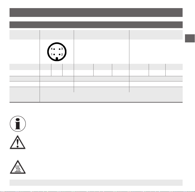
2.4 Labelling / safety marks
Product label
GB
Model
P# Product No.
S# Serial No.
Output signal
Power supply
Pin assignment
If the serial number becomes illegible (e.g. due to mechanical damage or overpainting),
traceability will no longer be possible.
Explanation of symbols
CE, Communauté Européenne
Instruments bearing this mark comply with the relevant European directives.
Voltage DC
8 WIKA operating instructions pressure transmitter, model MG-1
11609681.02 03/2013 GB/D/F/E
Page 9

3. Specications
3. Specications
Specications Model MG-1
Measuring range bar 6 10 16 200 300 400
Overpressure safety bar 20 20 32 500 800 800
Burst pressure bar 25 25 160 1200 1700 1700
Measuring range psi 100 150 200 3000 4000 5000
Overpressure safety psi 290 290 460 7200 11000 11000
Burst pressure psi 1450 1450 2300 17000 24000 24000
MPa, kPa and kg/cm² available; -1/0 bar or -30/0 inHg upon request
Level of cleanliness Measuring range < 30 bar/435 psi Measuring range > 30 bar/435 psi
■
Breathing gas free from oil and grease free from oil and grease
- Residual hydrocarbons mg/m² < 1000 < 1000
■
Medical standard per ISO 15001 per ISO 15001
- Residual hydrocarbons mg/m² < 550 < 220
- Particle size µm not applicable on request
■
Industrial standard Free from oil and grease
- Residual hydrocarbons mg/m² < 550 < 220
■
High industrial standard Free from oil and grease for
- Residual hydrocarbons mg/m² < 66 < 66
Materials
■
Process connection 316L and 13-8 PH
■
Case 316L
■
Electrical connection Highly resistant glass-bre reinforced plastic (PBT GF30)
for oxygen per ASTM Level D/E
and DIN 19247
oxygen per ASTM Level C
Free from oil and grease
for oxygen per ASTM Level D/E
and DIN 19247
Free from oil and grease for
oxygen per ASTM Level C
GB
11609681.02 03/2013 GB/D/F/E
9WIKA operating instructions pressure transmitter, model MG-1
Page 10

3. Specications
Specications Model MG-1
Output Output signal Power supply UBMax. resistive load R
GB
Operating current mA max. 10
Settling time ms ≤ 2
Non-linearity % of span ≤ ±0.5 (BFSL) per IEC 61298-2
Accuracy % of span ≤ ±2
Long-term stability % of span ≤ ±0.3 / year
Reference conditions
■
Temperature °C 15 ... 25
■
Humidity % 15 … 95 non-condensing
■
Ambient pressure mmHg 500 … 800
Permissible temperature ranges
■
Operation -20 ... +70 °C -4 ... +158 °F
■
Storage -25 ... +80 °C -13 ... +176 °F
Temperature error in
operating temperature range
CE conformity
■
Pressure equipment directive 97/23/EC
■
EMC directive 2004/108/EC, EN 61326 Emission (Group 1, Class B) and
% of span ≤ ±2.0
4 ... 20 mA, 2-wire DC 8 ... 30 V RA ≤ (UB – 7 V) / 0.02 A
0 ... 10 V, 3-wire DC 14 ... 30 V R
0 ... 5 V, 3-wire DC 8 ... 30 V R
1 ... 5 V, 3-wire DC 8 ... 30 V R
0.5…4.5 V ratiometric DC 5 V ± 5 % R
1)
> 10 kΩ
A
> 5 kΩ
A
> 5 kΩ
A
> 4.5 kΩ
A
Immunity (industrial locations)
A
10 WIKA operating instructions pressure transmitter, model MG-1
11609681.02 03/2013 GB/D/F/E
Page 11

3. Specications / 4. Design and function
Specications Model MG-1
Shock resistance g 40 (6 ms) per IEC 60068-2-27 (mechanical shock)
Vibration resistance g 20 (20 ... 2000 Hz, 120 min.) per IEC 60068-2-6
Reverse polarity protection U
Short-circuit resistance S
Weight kg approx. 0.08
1) Including non-linearity, hysteresis, zero-point and full scale value deviations (corresponds to measuring error per IEC 61298-2).
Calibrated in vertical mounting position with process connection facing downwards.
(Vibration under resonance)
vs. 0V
B
vs. 0V
+
For special model numbers, e. g. MG-10000, please note the specications stated on the
delivery note.
For further specications, see WIKA data sheet PE 81.44 and the order documentation.
When designing the system, please note that the values given (e.g. burst pressure,
overpressure safety) are dependent upon the material, thread and gasket used.
4. Design and function
4.1 Description
By means of a sensor element and by applying power, the prevailing pressure is converted into an
amplied standardised electrical signal via the deformation of a membrane. This electrical signal
varies in proportion to the pressure and can be evaluated accordingly.
GB
4.2 Scope of delivery
Cross-check scope of delivery with delivery note.
11609681.02 03/2013 GB/D/F/E
11WIKA operating instructions pressure transmitter, model MG-1
Page 12

5. Transport, packaging and storage
5. Transport, packaging and storage
5.1 Transport
Check the pressure transmitter for any damage that may have been caused during transportation.
GB
Obvious damage must be reported immediately.
A recieved-goods inspection determines the purity of the pressure transmitter. It is only
guaranteed if the packaging is undamaged or unopened.
5.2 Packaging
Do not remove packaging until just before mounting.
Keep the packaging as it will provide optimum protection during transport (e.g. change in
installation site, sending for repair).
5.3 Storage
Permissible conditions at the place of storage:
■
Storage temperature: -25 ... +80 °C
■
Humidity: 15 ... 95 % (no condensation)
Only ever store the pressure transmitter in its original packaging.
WARNING!
Before storing the pressure transmitter (following operation), remove any residual
media. This is of particular importance if the medium is hazardous to health,
e.g. caustic, toxic, carcinogenic, radioactive, etc.
12 WIKA operating instructions pressure transmitter, model MG-1
11609681.02 03/2013 GB/D/F/E
Page 13

6. Commissioning, operation
6. Commissioning, operation
Required tool: SW 24 open-ended spanner
WARNING!
Prior to commissioning, the pressure transmitter must be subjected to a visual
inspection.
Only use the pressure transmitter if it is in perfect condition with respect to safety.
Making the mechanical connection
■
To ensure that the wetted parts do not get soiled, the protection
cap should not be removed until immediately prior to mounting.
■
Use only BAM-certied gaskets.
■
During mounting, make sure that the sealing faces at the pressure
transmitter and the measuring point are clean and undamaged.
■
Only ever screw in, or unscrew, the pressure transmitter to the
max.
20 Nm
prescribed torque via the spanner-ats, and using tools which are
appropriate and clean for use with oxygen.
The correct torque depends on the dimensions of the process
connection and the gasket used (form/material). When screwing
in or unscrewing the pressure transmitter, do not use the housing or plug for purchase.
■
When screwing in, do not cross the threads.
■
Only lubricate thread with materials approved for use with oxygen.
■
For information on tapped holes and welding sockets, please refer to our Technical Information
IN 00.14 at www.wika.com.
GB
11609681.02 03/2013 GB/D/F/E
13WIKA operating instructions pressure transmitter, model MG-1
Page 14

6. Commissioning, operation
Types of sealing
per EN 837
GB
Making the electrical connection
■
Ground the pressure transmitter via the process connection.
■
This is Protection Class 3 equipment for connection at low voltages, which are separated from
the power supply or voltage by greater than AC 50 V or DC 120 V. Preferably, a connection
to an SELV or PELV circuit is recommended; alternatively protective measures from
HD 60346-4-41 (DIN VDE 0100-410).
■
Option for North America: The connection can be made in line with "Class 2 Circuits"
or "Class 2 Power Units" in accordance with CEC (Canadian Electrical Code) or
NEC (National Electrical Code).
■
Select a cable diameter that matches the cable gland of the plug. Make sure that the cable
gland of the mounted plug has a tight t. To guarantee the ingress protection, tighten the gland.
■
For cable outlets, make sure that no moisture enters at the cable end.
per DIN 3852-E
NPT, R and PT
Self-sealing thread typ
14 WIKA operating instructions pressure transmitter, model MG-1
11609681.02 03/2013 GB/D/F/E
Page 15
6. Commissioning, operation
Electrical connection
Circular connector
M12 x 1, 4-pin
2-wire UB = 1 0V = 3 UB = brown 0V = green UB = brown 0V = blue
3-wire U
Wire cross-section
Cable diameter - 3.6 mm 4.3 mm
Ingress protection
per IEC 60529
= 1 0V = 3 S+ = 4 UB = brown 0V = green S+ = white UB = brown 0V = blue S+ = black
B
- 3 x 0.14 mm
IP 67 IP 67 IP 67
The stated ingress protection only applies when plugged-in using line connectors that have
the appropriate ingress protection.
Functional check
The output signal must be proportional to the prevailing pressure. If this is not the
case, this may indicate a damaged membrane. In this case, see chapter "8. Faults".
WARNING!
■
Only open the connections once the system has been depressurised
■
Observe the working conditions in accordance with chapter "3. Specications".
■
Always operate the pressure transmitter within the overpressure safety range.
Cable outlet
2 m
Shielded cable outlet
2 m
2
3 x 0.14 mm
2
GB
CAUTION!
When touching the pressure transmitter, please note that the surfaces of the device
components can become hot during operation.
11609681.02 03/2013 GB/D/F/E
15WIKA operating instructions pressure transmitter, model MG-1
Page 16

7. Maintenance and cleaning
7. Maintenance and cleaning
7.1 Maintenance
This pressure transmitter is maintenance-free.
GB
Repairs must only be carried out by the manufacturer.
When performing maintenance work, the purity requirements of the applicable standards must be
observed.
7.2 Cleaning
CAUTION!
■
Before cleaning, correctly disconnect the pressure transmitter from the
pressure supply, switch it o and disconnect it from the mains.
■
Clean the pressure transmitter with a moist cloth.
■
Wash or clean the dismounted pressure transmitter before returning it in order to
protect personnel and the environment from exposure to residual media.
■
Residual media in dismounted pressure transmitters can result in a risk to
persons, the environment and equipment. Take sucient precautionary measures.
■
Do not use any pointed or hard objects for cleaning, as they may damage the
membrane of the process connection.
For information on returning the pressure transmitter see chapter "9.2 Return".
16 WIKA operating instructions pressure transmitter, model MG-1
11609681.02 03/2013 GB/D/F/E
Page 17

8. Faults
8. Faults
WARNING!
Open the connections only after the system has been depressurised!
First check whether the system is under pressure and whether the correct power supply and
correct wiring type (2-wire/3-wire) has been selected.
Faults Causes Measures
No output signal Cable break Check the through drilling
Deviating zero point signal Overpressure safety exceeded Observe the permissible overpressure
Deviating zero point signal Operating temperature too high/
Constant output signal upon
change in pressure
Signal span too small Mechanical overload caused by
Signal span varies EMC interference sources in
Signal span varies/inaccurate Operating temperature too high/
Signal span drops/too small Signal span drops/too small Contact manufacturer and replace pressure
If complaint is unjustied, we will charge you the complaint processing fees
low
Mechanical overload caused by
overpressure
overpressure
the environment; for example,
frequency converter
low
safety (see chapter "3. Specications")
Observe the permissible temperatures
(see Chapter "3. Specications")
Replace pressure transmitter; if it fails
repeatedly, contact the manufacturer
Replace pressure transmitter; if it fails
repeatedly, contact the manufacturer
Shield the pressure transmitter;
Cable shielding; remove source of interference
Observe the permissible temperatures
(see chapter "3. Specications")
transmitter
GB
11609681.02 03/2013 GB/D/F/E
17WIKA operating instructions pressure transmitter, model MG-1
Page 18

8. Faults / 9. Dismounting, return and disposal
CAUTION!
If deciencies cannot be eliminated by means of the measures listed above, shut
down the instrument immediately, and ensure that pressure and/or signal are no
GB
longer present, and secure the instrument from being put back into operation
inadvertently. In this case, contact the manufacturer. If a return is needed, please
follow the instructions given in chapter "9.2 Return".
9. Dismounting, return and disposal
WARNING!
Residual media in dismounted pressure transmitters can result in a risk to persons,
the environment and equipment.
Take sucient precautionary measures.
9.1 Dismounting
WARNING!
Only disconnect the pressure transmitter once the system has been
depressurised!
9.2 Return
WARNING!
Absolutely observe when shipping the pressure transmitter:
All pressure transmitters delivered to WIKA must be free from any kind of
hazardous substances (acids, leachate, solutions, etc.).
When returning the pressure transmitter, use the original packaging or a suitable transport
package.
18 WIKA operating instructions pressure transmitter, model MG-1
11609681.02 03/2013 GB/D/F/E
Page 19

9. Dismounting, return and disposal
Enclose the completed returns form with the pressure transmitter.
Information on returns can be found under the heading "Service" on our local website.
9.3 Disposal
Incorrect disposal may endanger the environment.
Dispose of instrument components and packaging materials in an environmentally compatible
way and in accordance with the country-specic waste disposal regulations.
GB
11609681.02 03/2013 GB/D/F/E
19WIKA operating instructions pressure transmitter, model MG-1
Page 20

Appendix 1: EC Declaration of Conformity for model MG-1
GB
20 WIKA operating instructions pressure transmitter, model MG-1
11609681.02 03/2013 GB/D/F/E
Page 21
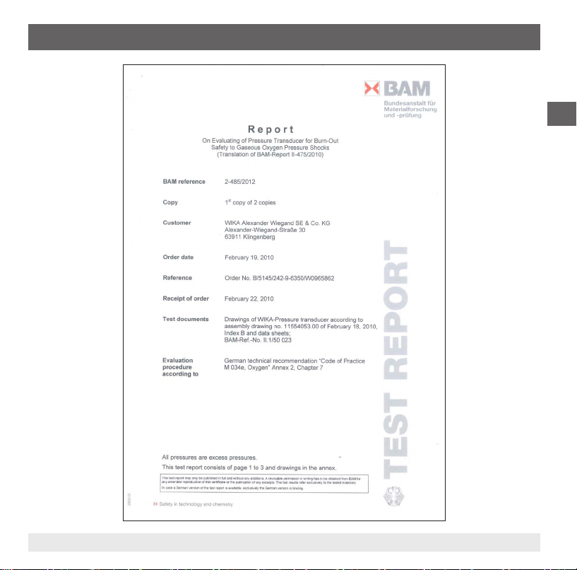
Appendix 2: BAM test report for model MG-1
GB
11609681.02 03/2013 GB/D/F/E
21WIKA operating instructions pressure transmitter, model MG-1
Page 22

Appendix 2: BAM test report for model MG-1
GB
22 WIKA operating instructions pressure transmitter, model MG-1
11609681.02 03/2013 GB/D/F/E
Page 23

Appendix 2: BAM test report for model MG-1
GB
11609681.02 03/2013 GB/D/F/E
23WIKA operating instructions pressure transmitter, model MG-1
Page 24

GB
24 WIKA operating instructions pressure transmitter, model MG-1
11609681.02 03/2013 GB/D/F/E
Page 25

Inhalt
Inhalt
1. Allgemeines 26
2. Sicherheit 28
3. Technische Daten 31
4. Aufbau und Funktion 33
5. Transport, Verpackung und Lagerung 34
6. Inbetriebnahme, Betrieb 36
7. Wartung und Reinigung 38
8. Störungen 39
9. Demontage, Rücksendung und Entsorgung 40
Anlage 1: EG-Konformitätserklärung für Typ MG-1
Anlage 2: BAM-Prüfbericht für Typ MG-1
Konformitätserklärungen nden Sie online unter www.wika.de.
11609681.02 03/2013 GB/D/F/E
D
42
43
25WIKA Betriebsanleitung Druckmessumformer, Typ MG-1
Page 26

1. Allgemeines
1. Allgemeines
■
Der in der Betriebsanleitung beschriebene Druckmessumformer wird nach dem aktuellen
Stand der Technik konstruiert und gefertigt.
Alle Komponenten unterliegen während der Fertigung strengen Qualitäts- und Umweltkriterien.
Unsere Managementsysteme sind nach ISO 9001 und ISO 14001 zertiziert.
D
■
Diese Betriebsanleitung gibt wichtige Hinweise zum Umgang mit dem Druckmessumformer.
Voraussetzung für sicheres Arbeiten ist die Einhaltung aller angegebenen Sicherheitshinweise
und Handlungsanweisungen.
■
Die für den Einsatzbereich des Druckmessumformers geltenden örtlichen Unfallverhütungsvorschriften und allgemeinen Sicherheitsbestimmungen einhalten.
■
Die Betriebsanleitung ist Produktbestandteil und muss in unmittelbarer Nähe des
Druckmessumformers für das Fachpersonal jederzeit zugänglich aufbewahrt werden.
■
Das Fachpersonal muss die Betriebsanleitung vor Beginn aller Arbeiten sorgfältig
durchgelesen und verstanden haben.
■
Die Haftung des Herstellers erlischt bei Schäden durch bestimmungswidrige Verwendung,
Nichtbeachten dieser Betriebsanleitung, Einsatz ungenügend qualizierten Fachpersonals
sowie eigenmächtiger Veränderung am Druckmessumformer.
■
Es gelten die allgemeinen Geschäftsbedingungen in den Verkaufsunterlagen.
■
Technische Änderungen vorbehalten.
■
Weitere Informationen:
- Internet-Adresse: www.wika.de
- zugehöriges Datenblatt: PE 81.44
- Anwendungsberater: Tel.:
(+49) 9372/132-8976
support-tronic@wika.de
E-Mail:
26 WIKA Betriebsanleitung Druckmessumformer, Typ MG-1
11609681.02 03/2013 GB/D/F/E
Page 27

1. Allgemeines
Symbolerklärung
WARNUNG!
… weist auf eine möglicherweise gefährliche Situation hin, die zum Tod oder zu
schweren Verletzungen führen kann, wenn sie nicht gemieden wird.
VORSICHT!
… weist auf eine möglicherweise gefährliche Situation hin, die zu geringfügigen oder
leichten Verletzungen bzw. Sach- und Umweltschäden führen kann, wenn sie nicht
gemieden wird.
Information
… hebt nützliche Tipps und Empfehlungen sowie Informationen für einen ezienten
und störungsfreien Betrieb hervor.
VORSICHT!
… weist auf eine möglicherweise gefährliche Situation hin, die durch heiße
Oberächen oder Flüssigkeiten zu Verbrennungen führen kann, wenn sie nicht
gemieden wird.
Abkürzungen
2-Leiter Zwei Anschlussleitungen dienen zur Spannungsversorgung.
Der Speisestrom ist das Messsignal
3-Leiter Zwei Anschlussleitungen dienen zur Spannungsversorgung.
Eine Anschlussleitung dient für das Messsignal
U
B
0V Negativer Versorgungsanschluss
S
+
Positiver Versorgungsanschluss
Positiver Messanschluss
D
11609681.02 03/2013 GB/D/F/E
27WIKA Betriebsanleitung Druckmessumformer, Typ MG-1
Page 28

2. Sicherheit
2. Sicherheit
WARNUNG!
Vor Montage, Inbetriebnahme und Betrieb sicherstellen, dass der richtige
Druckmessumformer hinsichtlich Messbereich, Ausführung und spezischen
D
2.1 Bestimmungsgemäße Verwendung
Der Druckmessumformer dient zum Umwandeln von Druck in ein elektrisches Signal.
Der Druckmessumformer ist ausschließlich für den hier beschriebenen bestimmungsgemäßen
Verwendungszweck konzipiert und konstruiert und darf nur dementsprechend verwendet werden.
Die technischen Spezikationen in dieser Betriebsanleitung sind einzuhalten.
Eine unsachgemäße Handhabung oder ein Betreiben des Druckmessumformers außerhalb
der technischen Spezikationen macht die sofortige Stilllegung und Überprüfung durch einen
autorisierten WIKA-Servicemitarbeiter erforderlich
Ansprüche jeglicher Art aufgrund von nicht bestimmungsgemäßer Verwendung sind
ausgeschlossen.
Messbedingungen ausgewählt wurde.
Bei Nichtbeachten können schwere Körperverletzungen und/oder Sachschäden
auftreten.
Weitere wichtige Sicherheitshinweise benden sich in den einzelnen Kapiteln dieser
Betriebsanleitung.
28 WIKA Betriebsanleitung Druckmessumformer, Typ MG-1
11609681.02 03/2013 GB/D/F/E
Page 29

2. Sicherheit
2.2 Personalqualikation
WARNUNG!
Verletzungsgefahr bei unzureichender Qualikation!
Unsachgemäßer Umgang kann zu erheblichen Personen- und Sachschäden führen.
Die in dieser Betriebsanleitung beschriebenen Tätigkeiten nur durch Fachpersonal
nachfolgend beschriebener Qualikation durchführen lassen.
Fachpersonal
Das Fachpersonal ist aufgrund seiner fachlichen Ausbildung, seiner Kenntnisse der Mess- und
Regelungstechnik und seiner Erfahrungen sowie Kenntnis der landesspezischen Vorschriften,
geltenden Normen und Richtlinien in der Lage, die beschriebenen Arbeiten auszuführen und
mögliche Gefahren selbstständig zu erkennen.
Spezielle Einsatzbedingungen verlangen weiteres entsprechendes Wissen, z. B. über
aggressive Medien.
2.3 Besondere Gefahren
WARNUNG!
Bei gefährlichen Messstoen wie z. B. Sauersto, Acetylen, brennbaren oder giftigen
Stoen, sowie bei Kälteanlagen, Kompressoren etc. müssen über die gesamten
allgemeinen Regeln hinaus die einschlägigen Vorschriften beachtet werden.
WARNUNG!
Messstoreste in ausgebauten Druckmessumformern können zur Gefährdung von
Personen, Umwelt und Einrichtung führen.
Ausreichende Vorsichtsmaßnahmen ergreifen.
D
11609681.02 03/2013 GB/D/F/E
29WIKA Betriebsanleitung Druckmessumformer, Typ MG-1
Page 30

2. Sicherheit
2.4 Beschilderung / Sicherheitskennzeichnungen
Typenschild
Typ
P# Erzeugnis-Nr.
S# Serien-Nr.
D
Ausgangssignal
Hilfsenergie
Anschlussbelegung
Wird die Seriennummer unleserlich (z. B. durch mechanische Beschädigung oder Übermalen), ist
eine Rückverfolgbarkeit nicht mehr möglich.
Symbolerklärung
CE, Communauté Européenne
Geräte mit dieser Kennzeichnung stimmen überein mit den zutreenden
europäischen Richtlinien.
Gleichspannung
30 WIKA Betriebsanleitung Druckmessumformer, Typ MG-1
11609681.02 03/2013 GB/D/F/E
Page 31

3. Technische Daten
3. Technische Daten
Technische Daten Typ MG-1
Messbereich bar 6 10 16 200 300 400
Überlastgrenze bar 20 20 32 500 800 800
Berstdruck bar 25 25 160 1200 1700 1700
Messbereich psi 100 150 200 3000 4000 5000
Überlastgrenze psi 290 290 460 7200 11000 11000
Berstdruck psi 1450 1450 2300 17000 24000 24000
MPa, kPa und kg/cm² verfügbar; -1/0 bar bzw. -30/0 inHg auf Anfrage
Reinheitsgrad Messbereich < 30 bar / 435 psi Messbereich > 30bar / 435 psi
■
Atemgas Öl- und fettfrei Öl- und fettfrei
- Restkohlenwasserstoe mg/m² < 1000 < 1000
■
Medizinstandard gemäß ISO 15001 gemäß ISO 15001
- Restkohlenwasserstoe mg/m² < 550 < 220
- Partikelgröße µm nicht zutreend auf Anfrage
■
Industriestandard
- Restkohlenwasserstoe mg/m² < 550 < 220
■
Hoher Industriestandard
- Restkohlenwasserstoe mg/m² < 66 < 66
Werkstoe
■
Prozessanschluss 316L und 13-8 PH
■
Gehäuse 316L
■
Elektrischer Anschluss Hochresistenter glasfaserverstärkter Kunststo (PBT GF 30)
Öl- und fettfrei für Sauersto nach
ASTM Level D/E und DIN 19247
Öl- und fettfrei für Sauersto nach
ASTM Level C
Öl- und fettfrei für Sauersto nach
ASTM Level D/E und DIN 19247
Öl- und fettfrei für Sauersto nach
ASTM Level C
D
11609681.02 03/2013 GB/D/F/E
31WIKA Betriebsanleitung Druckmessumformer, Typ MG-1
Page 32

3. Technische Daten
Technische Daten Typ MG-1
Ausgang Ausgangssignal
4 ... 20 mA, 2-Leiter DC 8 ... 30 V RA ≤ (UB – 7 V) / 0.02 A
0 ... 10 V, 3-Leiter DC 14 ... 30 V R
D
0 ... 5 V, 3-Leiter DC 8 ... 30 V R
1 ... 5 V, 3-Leiter DC 8 ... 30 V R
0,5 ... 4,5 V ratiometrisch
Betriebsstrom mA max. 10
Einschwingzeit ms ≤ 2
Nichtlinearität % d. Spanne ≤ ±0,5 (BFSL) nach IEC 61298-2
Genauigkeit % d. Spanne ≤ ±2
1)
Langzeitstabilität % d. Spanne ≤ ±0,3 / Jahr
Referenzbedingungen
■
Luftfeuchte % 15 … 95 nicht kondensierend
■
Umgebungsdruck mmHg 500 … 800
Zulässige Temperaturbereiche
■
Betrieb -20 ... +70 °C -4 ... +158 °F
■
Lagerung -25 ... +80 °C -13 ... +176 °F
Temperaturfehler im
% d. Spanne ≤ ±2,0
Betriebstemperaturbereich
CE-Konformität
■
Druckgeräterichtlinie 97/23/EG
■
EMV-Richtlinie 2004/108/EG, EN 61326 Emission (Gruppe 1, Klasse B) und
Störfestigkeit (industrieller Bereich)
Hilfsenergie U
Max. ohmsche Bürde R
B
A
A
A
DC 5 V ± 5 % RA > 4,5 kΩ
A
> 10 kΩ
> 5 kΩ
> 5 kΩ
32 WIKA Betriebsanleitung Druckmessumformer, Typ MG-1
11609681.02 03/2013 GB/D/F/E
Page 33

3. Technische Daten / 4. Aufbau und Funktion
Technische Daten Typ MG-1
Schockbelastbarkeit g 40 (6 ms) nach IEC 60068-2-27 (Schock mechanisch)
Vibrationsbelastbarkeit g 20 (20 ... 2000 Hz, 120 min.) nach IEC 60068-2-6
Kurzschlussfestigkeit S
Verpolschutz U
Gewicht kg ca. 0,08
1) Einschließlich Nichtlinearität, Hysterese, Nullpunkt- und Endwertabweichung (entspricht Messabweichung nach IEC 61298-2)
(Vibration bei Resonanz)
gegen 0V
+
gegen 0V
B
Bei Sondertypennummer, z. B. MG-10000 Spezikationen gemäß Lieferschein beachten.
Weitere technische Daten siehe WIKA Datenblatt PE 81.44 und Bestellunterlagen.
Bei der Auslegung der Anlage beachten, dass die angegebenen Werte (z. B. Berstdruck, Überlastgrenze) in Abhängigkeit vom verwendeten Material, Gewinde und
Dichtung gelten.
4. Aufbau und Funktion
4.1 Beschreibung
Mittels Sensorelement und unter Zuführung von Hilfsenergie wird über die Verformung einer
Membran der anstehende Druck in ein verstärktes standardisiertes elektrisches Signal
umgewandelt. Dieses elektrische Signal verändert sich proportional zum Druck und kann
entsprechend ausgewertet werden.
D
4.2 Lieferumfang
Lieferumfang mit dem Lieferschein abgleichen.
11609681.02 03/2013 GB/D/F/E
33WIKA Betriebsanleitung Druckmessumformer, Typ MG-1
Page 34

5. Transport, Verpackung und Lagerung
5. Transport, Verpackung und Lagerung
5.1 Transport
Druckmessumformer auf eventuell vorhandene Transportschäden untersuchen.
Oensichtliche Schäden unverzüglich mitteilen.
D
Bei einer Eingangskontrolle die Reinheit des Druckmessumformers erhalten. Diese ist nur
gewährleistet, wenn die Verpackung unbeschädigt, bzw. ungeönet ist.
5.2 Verpackung
Verpackung erst unmittelbar vor der Montage entfernen.
Die Verpackung aufbewahren, denn diese bietet bei einem Transport einen optimalen Schutz
(z. B. wechselnder Einbauort, Reparatursendung).
5.3 Lagerung
Zulässige Bedingungen am Lagerort:
■
Lagertemperatur: -25 ... +80 °C
■
Feuchtigkeit: 15 ... 95 % (keine Betauung)
Den Druckmessumformer nur in Originalverpackung einlagern.
WARNUNG!
Vor der Einlagerung des Druckmessumformers (nach Betrieb) alle anhaftenden
Messstoreste entfernen. Dies ist besonders wichtig, wenn der Messsto
gesundheitsgefährdend ist, wie z. B. ätzend, giftig, krebserregend, radioaktiv, usw.
34 WIKA Betriebsanleitung Druckmessumformer, Typ MG-1
11609681.02 03/2013 GB/D/F/E
Page 35

6. Inbetriebnahme, Betrieb
6. Inbetriebnahme, Betrieb
Benötigtes Werkzeug: Maulschlüssel SW 24
WARNUNG!
Vor der Inbetriebnahme den Druckmessumformer optisch überprüfen.
Den Druckmessumformer nur in sicherheitstechnisch einwandfreiem Zustand einsetzen.
Montage mechanischer Anschluss
■
Sicherstellen, dass messstoberührende Teile nicht verschmutzt
werden, daher Schutzkappe erst unmittelbar vor der Montage
entfernen.
■
Nur BAM zertizierte Dichtungen verwenden.
■
Bei der Montage auf eine saubere und unbeschädigte
Dichtächen am Druckmessumformer und der Messstelle achten.
■
Den Druckmessumformer nur über die Schlüsseläche,
mit einem geeigneten und gereinigten Werkzeug für den
Sauerstoeinsatz, mit dem vorgeschriebenen Drehmoment einbzw. ausschrauben.
Das richtige Drehmoment ist abhängig von der Dimension des Prozessanschlusses sowie der
verwendeten Dichtung (Form/Werksto). Beim Ein- bzw. Ausschrauben nicht das Gehäuse
oder den Stecker als Angrisäche verwenden.
■
Beim Einschrauben die Gewindegänge nicht verkanten.
■
Gewinde nur mit Materialen schmieren, die für den Sauerstoeinsatz zugelassenen sind.
■
Angaben zu Einschraublöchern und Einschweißstutzen siehe Technische Information IN 00.14
unter www.wika.de.
11609681.02 03/2013 GB/D/F/E
D
max.
20 Nm
35WIKA Betriebsanleitung Druckmessumformer, Typ MG-1
Page 36

6. Inbetriebnahme, Betrieb
Dichtungsarten
nach EN 837
nach DIN 3852-E NPT, R und PT
D
Selbstdichtende Gewindeart
Montage elektrischer Anschluss
■
Den Druckmessumformer über den Prozessanschluss erden.
■
Dies ist ein Betriebsmittel der Schutzklasse 3 zum Anschluss an Kleinspannungen, die von der
Netzspannung oder Spannung größer AC 50 V bzw. DC 120 V getrennt sind. Zu bevorzugen
ist ein Anschluss an SELV- oder PELV- Stromkreise; alternativ ist eine Schutzmaßnahme aus
HD 60346-4-41 (DIN VDE 0100-410) zu empfehlen.
■
Alternativ für Nordamerika: Der Anschluss kann auch an "Class 2 Circuits" oder "Class 2
Power Units" gemäß CEC (Canadian Electrical Code) oder NEC (National Electrical Code)
erfolgen.
■
Den Kabeldurchmesser passend zur Kabeldurchführung des Steckers wählen. Darauf achten,
dass die Kabelverschraubung des montierten Steckers korrekt sitzt. Verschraubung festziehen
um die Schutzart zu gewährleisten.
■
Bei Kabelausgängen sicherstellen, dass am Ende des Kabels keine Feuchtigkeit eintritt.
36 WIKA Betriebsanleitung Druckmessumformer, Typ MG-1
11609681.02 03/2013 GB/D/F/E
Page 37

6. Inbetriebnahme, Betrieb
Elektrischer Anschluss
Rundstecker M12 x 1
4-polig
Kabelausgang
2 m
Geschirmter Kabelausgang
2 m
D
2-Leiter
3-Leiter
Aderquerschnitt
Kabeldurchmesser
Schutzart nach
IEC 60529
UB = 1 0V = 3
UB = 1 0V = 3 S+ = 4
- 3 x 0,14 mm 3 x 0,14 mm
- 3,6 mm
IP 67 IP 67 IP 67
Die angegebenen Schutzarten gelten nur im gesteckten Zustand mit Leitungssteckern
entsprechender Schutzart.
Funktionsprüfung
Das Ausgangssignal muss sich dem anstehenden Druck proportional verhalten. Ist
dies nicht der Fall, kann das ein Hinweis auf eine Beschädigung der Membrane sein.
In diesem Fall siehe Kapitel „8. Störungen“.
WARNUNG!
■
Anschlüsse nur im drucklosen Zustand önen
■
Betriebsparameter gemäß Kapitel „3.Technische Daten“ beachten.
■
Druckmessumformer immer innerhalb des Überlastgrenzbereichs betreiben!
VORSICHT!
Beim Berühren des Druckmessumformers beachten, dass die Oberächen der
Gerätekomponenten während des Betriebes heiß werden können.
11609681.02 03/2013 GB/D/F/E
UB = braun
UB = braun
2
0V = grün UB = braun 0V = blau
0V = grün S+ = weiß UB = braun 0V = blau S+ = schwarz
2
4,3 mm
37WIKA Betriebsanleitung Druckmessumformer, Typ MG-1
Page 38

7. Wartung und Reinigung
7. Wartung und Reinigung
7.1 Wartung
Dieser Druckmessumformer ist wartungsfrei.
Reparaturen sind ausschließlich vom Hersteller durchzuführen.
D
Bei Instandhaltungsarbeiten die Reinheitsanforderungen der geltenden Normen einhalten.
7.2 Reinigung
VORSICHT!
■
Vor der Reinigung den Druckmessumformer ordnungsgemäß von der
Druckversorgung trennen, ausschalten und vom Netz trennen.
■
Den Druckmessumformer mit einem feuchten Tuch reinigen.
■
Ausgebauten Druckmessumformer vor der Rücksendung spülen bzw. säubern,
um Personen und Umwelt vor Gefährdung durch anhaftende Messstoreste zu
schützen.
■
Messstoreste in ausgebauten Druckmessumformern können zur Gefährdung von
Personen, Umwelt und Einrichtung führen. Ausreichende Vorsichtsmaßnahmen
ergreifen.
■
Keine spitzen bzw. harten Gegenstände zur Reinigung verwenden, diese können
die Membrane des Prozessanschlusses beschädigen.
Hiweise zur Rücksendung des Druckmessumformers siehe Kapitel
„9.2 Rücksendung“.
38 WIKA Betriebsanleitung Druckmessumformer, Typ MG-1
11609681.02 03/2013 GB/D/F/E
Page 39

8. Störungen
8. Störungen
WARNUNG!
Anschlüsse nur im drucklosen Zustand önen!
Vorab prüfen, ob Druck ansteht und dass die richtige Spannungsversorgung und die richtige
Verdrahtungsart (2-Leiter/3-Leiter) gewählt wurde.
Störungen Ursachen Maßnahmen
Kein Ausgangssignal Leitungsbruch Durchgang überprüfen
Abweichendes Nullpunktsignal Überlastgrenze überschritten Zulässige Überlastgrenze einhalten
Abweichendes Nullpunktsignal Zu hohe/niedrige
Gleichbleibendes Ausgangssignal bei Druckänderung
Signalspanne zu klein Mechanische Überlastung durch
Signalspanne schwankend EMV-Störquellen in Umgebung,
Signalspanne schwankend/
ungenau
Signalspanne fällt ab/zu klein Signalspanne fällt ab/zu klein Hersteller kontaktieren und
Im unberechtigten Reklamationsfall berechnen wir die Reklamationsbearbeitungskosten.
11609681.02 03/2013 GB/D/F/E
Einsatztemperaturen
Mechanische Überlastung durch
Überdruck
Überdruck
z. B. Frequenzumrichter
Zu hohe/niedrige
Einsatztemperaturen
(siehe Kapitel „3.Technische Daten“)
Zulässige Temperaturen einhalten
(siehe Kapitel „3.Technische Daten“)
Druckmessumformer austauschen; bei
wiederholtem Ausfall Rücksprache mit
Hersteller
Druckmessumformer austauschen; bei
wiederholtem Ausfall Rücksprache mit
Hersteller
Druckmessumformer abschirmen;
Leitungsabschirmung; Störquelle entfernen
Zulässige Temperaturen einhalten
(siehe Kapitel „3.Technische Daten“)
Druckmessumformer austauschen
D
39WIKA Betriebsanleitung Druckmessumformer, Typ MG-1
Page 40

8. Störungen / 9. Demontage, Rücksendung und Entsorgung
VORSICHT!
Können Störungen mit Hilfe der oben aufgeführten Maßnahmen nicht
beseitigt werden, ist der Druckmessumformer unverzüglich außer Betrieb zu
setzen, sicherzustellen, dass kein Druck bzw. Signal mehr anliegt und gegen
versehentliche Inbetriebnahme zu schützen. In diesem Falle Kontakt mit dem
D
Hersteller aufnehmen. Bei notwendiger Rücksendung die Hinweise unter
Kapitel „9.2 Rücksendung“ beachten.
9. Demontage, Rücksendung und Entsorgung
WARNUNG!
Messstoreste in ausgebauten Druckmessumformern können zur Gefährdung von
Personen, Umwelt und Einrichtung führen.
Ausreichende Vorsichtsmaßnahmen ergreifen.
9.1 Demontage
WARNUNG!
Druckmessumformer nur im drucklosen Zustand demontieren!
9.2 Rücksendung
WARNUNG!
Beim Versand des Druckmessumformers unbedingt beachten:
Alle an WIKA gelieferten Druckmessumformer müssen frei von Gefahrstoen
(Säuren, Laugen, Lösungen, etc.) sein.
40 WIKA Betriebsanleitung Druckmessumformer, Typ MG-1
11609681.02 03/2013 GB/D/F/E
Page 41

9. Demontage, Rücksendung und Entsorgung
Zur Rücksendung des Druckmessumformers die Originalverpackung oder eine geeignete
Transportverpackung verwenden.
Dem Druckmessumformer das Rücksendeformular ausgefüllt beifügen.
Hinweise zur Rücksendung benden sich in der Rubrik „Service“ auf unserer lokalen
Internetseite.
9.3 Entsorgung
Durch falsche Entsorgung können Gefahren für die Umwelt entstehen.
Gerätekomponenten und Verpackungsmaterialien entsprechend den landesspezischen
Abfallbehandlungs- und Entsorgungsvorschriften umweltgerecht entsorgen.
D
11609681.02 03/2013 GB/D/F/E
41WIKA Betriebsanleitung Druckmessumformer, Typ MG-1
Page 42

Anlage 1: EG-Konformitätserklärung für Typ MG-1
D
42 WIKA Betriebsanleitung Druckmessumformer, Typ MG-1
11609681.02 03/2013 GB/D/F/E
Page 43

Anlage 2: BAM-Prüfbericht für Typ MG-1
D
11609681.02 03/2013 GB/D/F/E
43WIKA Betriebsanleitung Druckmessumformer, Typ MG-1
Page 44

Anlage 2: BAM-Prüfbericht für Typ MG-1
D
44 WIKA Betriebsanleitung Druckmessumformer, Typ MG-1
11609681.02 03/2013 GB/D/F/E
Page 45

Anlage 2: BAM-Prüfbericht für Typ MG-1
D
11609681.02 03/2013 GB/D/F/E
45WIKA Betriebsanleitung Druckmessumformer, Typ MG-1
Page 46

D
46 WIKA Betriebsanleitung Druckmessumformer, Typ MG-1
11609681.02 03/2013 GB/D/F/E
Page 47

Sommaire
Sommaire
1. Généralités 48
2. Sécurité 50
3. Spécications 53
4. Conception et fonction 55
5. Transport, emballage et stockage 56
6. Mise en service, exploitation 57
7. Entretien et nettoyage 60
8. Dysfonctionnements 61
9. Démontage, retour et mise au rebut 62
F
Annexe 1: Déclaration de conformité CE pour type MG-1
Annexe 2: Rapport de contrôle BAM pour type MG-1
Déclarations de conformité se trouvent sur www.wika.fr.
11609681.02 03/2013 GB/D/F/E
64
65
47WIKA mode d'emploi transmetteur de pression, type MG-1
Page 48

1. Généralités
1. Généralités
■
Le transmetteur de pression décrit dans le présent mode d’emploi est conçu et fabriqué selon
les dernières technologies en vigueur. Tous les composants sont soumis à des critères de
qualité et d’environnement stricts durant la fabrication. Nos systèmes de gestion sont certiés
selon ISO 9001 et ISO 14001.
■
Ce mode d'emploi donne des indications importantes concernant l'utilisation du transmetteur
F
de pression. Il est possible de travailler en toute sécurité avec ce produit en respectant toutes
les consignes de sécurité et d'utilisation.
■
Respecter les prescriptions locales de prévention contre les accidents et les prescriptions
générales de sécurité en vigueur pour le domaine d'application du transmetteur de pression.
■
Le mode d'emploi fait partie de l'instrument et doit être conservé à proximité immédiate du
transmetteur de pression et accessible à tout moment pour le personnel qualié.
■
Le personnel qualié doit, avant de commencer toute opération, avoir lu soigneusement et
compris le mode d'emploi.
■
La responsabilité du fabricant n'est pas engagée en cas de dommages provoqués par une
utilisation non conforme à l'usage prévu, de non respect de ce mode d'emploi, d'utilisation
de personnel peu qualié de même qu'en cas de modications du transmetteur de pression
eectuées par l'utilisateur.
■
Les conditions générales de vente mentionnées dans les documents de vente s'appliquent.
■
Sous réserve de modications techniques.
■
Pour obtenir dautres informations :
- Consulter notre site internet : www.wika.fr
- Fiche technique correspondante : PE 81.44
- Conseiller applications : Tél. : (+33) 1 343084-84
E-Mail: info@wika.fr
48 WIKA mode d'emploi transmetteur de pression, type MG-1
11609681.02 03/2013 GB/D/F/E
Page 49

1. Généralités
Explication des symboles
AVERTISSEMENT !
… indique une situation présentant des risques susceptibles de provoquer la mort ou
des blessures graves si elle n'est pas évitée.
ATTENTION !
… indique une situation potentiellement dangereuse et susceptible de provoquer de
légères blessures ou des dommages matériels et pour l'environnement si elle n'est
pas évitée.
Information
… met en exergue les conseils et recommandations utiles de même que les
informations permettant d'assurer un fonctionnement ecace et normal.
ATTENTION !
… indique une situation présentant des risques susceptibles de provoquer des
brûlures dues à des surfaces ou liquides chauds si elle n'est pas évitée.
Abréviations
2 ls Deux câbles de raccordement sont utilisés pour l'alimentation.
Le signal de mesure fournit également le courant d'alimentation.
3 ls Deux câbles de raccordement sont utilisés pour l'alimentation.
Un câble de raccordement est utilisé pour le signal de mesure.
U
B
Borne de courant positive
0V Borne de courant négative
S
+
11609681.02 03/2013 GB/D/F/E
Borne de mesure positive
F
49WIKA mode d'emploi transmetteur de pression, type MG-1
Page 50

2. Sécurité
2. Sécurité
AVERTISSEMENT !
Avant le montage, la mise en service et le fonctionnement, s'assurer que le
transmetteur de pression a été choisi de façon adéquate, en ce qui concerne
l'étendue de mesure, la version et les conditions de mesure spéciques.
F
2.1 Utilisation conforme à l'emploi prévu
Le transmetteur de pression permet de convertir la pression en un signal électrique.
Le transmetteur de pression est conçu et construit exclusivement pour une utilisation conforme à
l'usage prévu décrit ici et ne doit être utilisé qu'en conséquence.
Les spécications techniques mentionnées dans ce mode d'emploi doivent être respectées.
En cas d'utilisation inadéquate ou de fonctionnement du transmetteur de pression en dehors
des spécications techniques, un arrêt et contrôle doivent être immédiatement eectués par un
collaborateur autorisé du service de WIKA.
Aucune réclamation ne peut être recevable en cas d'utilisation non conforme à l'usage prévu.
Un non-respect de cette consigne peut entraîner des blessures corporelles graves et/
ou des dégâts matériels.
Vous trouverez d'autres consignes de sécurité dans les sections individuelles du
présent mode d'emploi.
50 WIKA mode d'emploi transmetteur de pression, type MG-1
11609681.02 03/2013 GB/D/F/E
Page 51

2. Sécurité
2.2 Qualication du personnel
AVERTISSEMENT !
Danger de blessure en cas de qualication insusante !
Une utilisation non conforme peut entraîner d'importants dommages corporels et
matériels.
Les opérations décrites dans ce mode d'emploi ne doivent être eectuées que par un
personnel ayant la qualication décrite ci-après.
Personnel qualié
Le personnel qualié est, en raison de sa formation spécialisée, de ses connaissances dans le
domaine de la technique de mesure et de régulation et de ses expériences de même que de
sa connaissance des prescriptions nationales des normes et directives en vigueur, en mesure
d'eectuer les travaux décrits et de reconnaître automatiquement les dangers potentiels.
Les conditions d'utilisation spéciales exigent également une connaissance adéquate par exemple
des liquides agressifs.
2.3 Dangers particuliers
AVERTISSEMENT !
Dans le cas de uides de mesure dangereux comme notamment l'oxygène, l'acétylène, les substances combustibles ou toxiques, ainsi que dans le cas d'installations
de réfrigération, de compresseurs etc., les directives appropriées existantes doivent
être observées en plus de l'ensemble des règles générales.
F
AVERTISSEMENT !
Les restes de uides se trouvant dans des appareils démontés peuvent mettre en
danger les personnes, l'environnement ainsi que l'installation.
Prendre des mesures de sécurité susantes.
11609681.02 03/2013 GB/D/F/E
51WIKA mode d'emploi transmetteur de pression, type MG-1
Page 52

2. Sécurité
2.4 Etiquetage / Marquages de sécurité
Plaque signalétique
Type
F
P# N° Produit
S# N° Série
Signal de sortie
Alimentation
Conguration du
raccordement
Si le numéro de série devient illisible (par ex. à cause de dommages mécaniques ou de peinture),
aucune traçabilité n'est plus possible.
Explication des symboles
CE, Communauté Européenne
Les appareils avec ce marquage sont conformes aux directives européennes
pertinentes.
Tension DC
52 WIKA mode d'emploi transmetteur de pression, type MG-1
11609681.02 03/2013 GB/D/F/E
Page 53

3. Spécications
3. Spécications
Spécications Type MG-1
Etendue de mesure bar 6 10 16 200 300 400
Sécurité contre la surpression
Pression d'éclatement bar 25 25 160 1200 1700 1700
Etendue de mesure psi 100 150 200 3000 4000 5000
Sécurité contre la surpression
Pression d'éclatement psi 1450 1450 2300 17000 24000 24000
Degré de propreté
■
Gaz respiratoire Exempt d'huiles et de graisses Exempt d'huiles et de graisses
- Hydrocarbures résiduels mg/m² < 1000 < 1000
■
Standard médical En conformité avec ISO 15001 En conformité avec ISO 15001
- Hydrocarbures résiduels mg/m² < 550 < 220
- Taille des particules µm Non applicable sur demande
■
Standard industriel Exempt d'huiles et de graisses
- Hydrocarbures résiduels mg/m² < 550 < 220
■
Haut standard industriel Exempt d'huiles et de graisses
- Hydrocarbures résiduels mg/m² < 66 < 66
Matériaux
■
Raccord de pression 316L et 13-8 PH
■
Boîtier 316L
■
Raccordement électrique Plastique renforcé de bres de verre hautement résistant (PBT GF30)
bar 20 20 32 500 800 800
psi 290 290 460 7200 11000 11000
MPa, kPa et kg/cm² disponibles ; -1/0 bar ou -30/0 inHg sur demande
Etendue de mesure < 30 bar/435 psi Etendue de mesure > 30 bar/435 psi
pour l'oxygène en conformité avec
ASTM Level D/E et DIN 19247
pour l'oxygène en conformité avec
ASTM Level C
Exempt d'huiles et de graisses
pour l'oxygène en conformité avec
ASTM Level D/E et DIN 19247
Exempt d'huiles et de graisses
pour l'oxygène en conformité avec
ASTM Level C
F
11609681.02 03/2013 GB/D/F/E
53WIKA mode d'emploi transmetteur de pression, type MG-1
Page 54

3. Spécications
Spécications Type MG-1
Sortie Signal de sortie Alimentation U
4 ... 20 mA, 2 ls 8 ... 30 VDC RA ≤ (UB – 7 V) / 0,02 A
0 ... 10 V, 3 ls 14 ... 30 VDC R
0 ... 5 V, 3 ls 8 ... 30 VDC R
1 ... 5 V, 3 ls 8 ... 30 VDC R
F
0,5 … 4,5 V ratiométrique
5 VDC ± 5 % RA > 4,5 kOhm
Courant de service mA max. 10
Durée de réglage ms ≤ 2
Non-linéarité % de l'échelle ≤ ±0,5 (BFSL) selon IEC 61298-2
Précision % de l'échelle ≤ ±2
1)
Stabilité à long terme % de l'échelle ≤ ±0,3 / an
Conditions de référence
■
Température °C 15 ... 25
■
Humidité % 15 … 95 sans condensation
■
Pression ambiante mmHg 500 … 800
Plages de température
admissibles
■
Température de service -20 ... +70 °C -4 ... +158 °F
■
Stockage -25 ... +80 °C -13 ... +176 °F
Erreur de température
Plage de température
% de l'échelle ≤ ±2,0
admissible
Conformité CE
■
Directive relative aux
équipements sous
97/23/CE
pression
■
Directive CEM 2004/108/CE, EN 61326 Emission (Groupe 1, Classe B) et
immunité (sites industriels)
54 WIKA mode d'emploi transmetteur de pression, type MG-1
Charge résistive max.
B
> 10 kOhm
A
> 5 kOhm
A
> 5 kOhm
A
R
A
11609681.02 03/2013 GB/D/F/E
Page 55

3. Spécications / 4. Conception et fonction
Spécications Type MG-1
Résistance aux chocs g 40 (6 ms) selon IEC 60068-2-27 (choc mécanique)
Résistance aux vibrations g 20 (20 ... 2000 Hz, 120 min.) selon IEC 60068-2-6
Résistance court-circuit S
Protection contre l’inversion de polarité U
Poids kg env. 0,08
1) Y compris la non-linéarité, l'hystérésis, les déviations de point zéro et de valeur nale (correspond à mesurer la déviation en accord avec
IEC 61298-2).
(Vibrations sous résonance)
vs. 0V
+
vs. 0V
B
Pour plus d'informations sur les numéros de modèle spéciaux, par ex. MG-10000, voir les
spécications gurant sur le bon de livraison.
Pour de plus amples spécications, voir la che technique WIKA PE 81.44 et la documentation de
commande.
Lors de la conception du système, noter que les valeurs indiquées (par ex. pression
d'éclatement, sécurité contre la surpression) dépendent du matériau, du letage et
du joint utilisés.
4. Conception et fonction
4.1 Description
Un élément capteur et l'application de courant permettent de convertir la pression disponible
en un signal électrique standardisé et amplié par la déformation d'une membrane. Ce signal
électrique varie en fonction de la pression et peut être évalué.
4.2 Détail de la livraison
Comparer le détail de la livraison avec le bordereau de livraison.
11609681.02 03/2013 GB/D/F/E
F
55WIKA mode d'emploi transmetteur de pression, type MG-1
Page 56

5. Transport, emballage et stockage
5. Transport, emballage et stockage
5.1 Transport
Vérier s'il existe des dégâts sur le transmetteur de pression liés au transport.
Communiquer immédiatement les dégâts constatés.
La pureté du transmetteur de pression est déterminée lors du contrôle à la réception des
F
marchandises. La pureté ne peut être garantie que si l'emballage est en parfait état et n'est pas
ouvert.
5.2 Emballage
N'enlever l'emballage qu'avant le montage.
Conserver l'emballage, celui-ci ore, lors d'un transport, une protection optimale
(par ex. changement de lieu d'utilisation, renvoi pour réparation).
5.3 Stockage
Conditions admissibles sur le lieu de stockage :
■
Température de stockage : -25 ... +80 °C
■
Humidité : 0 ... 95 % (sans condensation)
Toujours conserver le transmetteur de pression dans son emballage original.
AVERTISSEMENT !
Enlevez tous les restes de uides adhérents avant l'entreposage du transmetteur de
pression (après le fonctionnement). Ceci est particulièrement important lorsque le
uide représente un danger pour la santé, comme p. ex. des substances corrosives,
toxiques, cancérogènes, radioactives, etc.
56 WIKA mode d'emploi transmetteur de pression, type MG-1
11609681.02 03/2013 GB/D/F/E
Page 57

6. Mise en service, exploitation
6. Mise en service, exploitation
Outil requis : Ouverture de clé (SW) 24 clé à fourche
Inspection de sécurité
Avant la mise en service, le transmetteur de pression doit être soumis à un contrôle
visuel.
Le transmetteur de pression ne doit être utilisé qu'en parfait état de sécurité
technique.
Raccordement mécanique
■
Pour protéger les pièces en contact contre l'encrassement, le
capuchon de protection ne doit être enlevé qu'immédiatement
avant le montage.
■
Utiliser uniquement des joints certiés BAM.
■
Pendant le montage, assurez-vous que les surfaces d'étanchéité
sur le transmetteur de pression et le point de mesure sont
propres et intacts.
■
Ne visser ou dévisser la transmetteur de pression que par le
couple de serrage prescrit à l'aide du méplat en utilisant des
outils adéquats et propres pour l'utilisation d'oxygène.
Le couple correct dépend des dimensions du raccord process et du joint utilisé
(forme/matériau). Lorsque vous vissez ou dévissez le transmetteur de pression, n'utilisez pas
le boîtier ou le connecteur pour eectuer cette opération.
■
Lorsque vous vissez, ne pas croiser les lets.
■
Ne graisser le letage qu'en utilisant de produits adaptés à l'utilisation d'oxygène.
■
Pour plus d'informations sur les trous letés et les raccords à souder, voir notre documentation
technique IN 00.14 sur notre site internet www.wika.fr.
Max.
20 Nm
F
11609681.02 03/2013 GB/D/F/E
57WIKA mode d'emploi transmetteur de pression, type MG-1
Page 58

6. Mise en service, exploitation
Types d'étanchéité
selon EN 837
selon DIN 3852-E
NPT, R et PT
F
Filet type auto-étanchéiant
Raccordement électrique
■
Mettre à la terre le transmetteur de pression au moyen du raccord de pression.
■
C'est un matériel de la classe de protection 3 pour le raccordement à des faibles tensions
qui sont séparées de la tension réseau ou tension supérieure à 50 VAC ou 120 VDC. Il faut
privilégier un raccordement à des circuits électriques SELV ou PELV; une mesure de protection
en HD 60 346-4-41 (DIN VDE 0100-410) peut être recommandée comme alternative.
■
Option pour l'Amérique du Nord : Le raccordement peut être également eectué sur "circuits
classe 2" ou des "unités de puissance classe 2" conformément au CEC (Canadian Electrical
Code) ou NEC (National Electrical Code).
■
Choisir un diamètre de câble qui correspond au presse étoupe. S'assurer que le presse étoupe
du connecteur monté est bien serré. Pour garantir le degré de protection, serrer le presse
étoupe.
■
Protéger les départs de câble contre la pénétration d'humidité.
58 WIKA mode d'emploi transmetteur de pression, type MG-1
11609681.02 03/2013 GB/D/F/E
Page 59

6. Mise en service, exploitation
Raccordement électrique
Connecteur M12 x 1
4 plots
2 ls UB = 1 0V = 3
3 ls UB = 1 0V = 3 S+ = 4
Section du
conducteur
Diamètre de câble - 3,6 mm 4,3 mm
Degré de protection
selon IEC 60529
- 3 x 0,14 mm
IP 67 IP 67 IP 67
Le degré de protection mentionné n’est valable que lorsque le contre-connecteur
raccordé possède également le degré de protection requis.
Contrôle de fonctionnement
Le signal de sortie doit être proportionnel à la pression disponible. Si cela n'est pas le
cas, cela pourrait indiquer un endommagement de la membrane. Dans ce cas, voir le
chapitre "8. Dysfonctionnements".
AVERTISSEMENT !
■
N'ouvrez les connexions qu'après que le système ait été dépressurisé
■
Observez les conditions de fonctionnement conformément au chapitre
"3. Spécications".
■
Ne faites fonctionner le transmetteur de pression que dans l'échelle de sécurité
contre la surpression.
Sortie de câble
2 m
UB = marron 0V = vert UB = marron 0V = bleu
UB = marron 0V = vert S+ = blanc UB = marron 0V = bleu S+ = noir
2
Sortie de câble blindé
2 m
3 x 0,14 mm
F
2
ATTENTION !
Lors de tout contact avec le transmetteur de pression, notez que les surfaces de l'appareil peuvent devenir chaudes lors du fonctionnement.
11609681.02 03/2013 GB/D/F/E
59WIKA mode d'emploi transmetteur de pression, type MG-1
Page 60

7. Entretien et nettoyage
7. Entretien et nettoyage
7.1 Entretien
Ce transmetteur de pression ne nécessite aucun entretien.
Les réparations ne doivent être eectuées que par le fabricant.
F
Lors des travaux d'entretien, veiller à observer les exigences concernant la pureté dénies dans
les standards en vigueur.
7.2 Nettoyage
ATTENTION !
■
Avant le nettoyage, il est impératif de mettre le transmetteur de pression hors
pression, de le mettre hors circuit et de le séparer du secteur.
■
Nettoyer le transmetteur de pression avec un chion humide.
■
Laver ou nettoyer le transmetteur de pression démonté avant de le retourner an
de protéger le personnel et l‘environnement contre le danger lié aux restes de
uides adhérents.
■
Les restes de uides se trouvant dans les transmetteurs de pression démontés
peuvent mettre en danger les personnes, l'environnement ainsi que l'installation.
Prendre des mesures de sécurité susantes.
■
Ne pas utiliser d'objets pointus ou durs pour le nettoyage an de ne pas
endommager la membrane du raccord de pression.
Indications concernant le retour du transmetteur de pression, voir chapitre
"9.2 Retour".
60 WIKA mode d'emploi transmetteur de pression, type MG-1
11609681.02 03/2013 GB/D/F/E
Page 61

8. Dysfonctionnements
8. Dysfonctionnements
AVERTISSEMENT !
N'ouvrez les connexions qu'après que le système ait été dépressurisé !
Vériez d'abord si le système est sous pression et l'alimentation et le type de branchement
(2 ls / 3 ls) sont corrects.
Dysfonctionnements Raisons Mesures
Pas de signal de sortie Câble sectionné Vérier le perçage
Déviation du signal de point
zéro
Déviation du signal de point
zéro
Signal de sortie constant après
une variation de pression
Plage de signaux trop petite Surcharge mécanique causé par
Le signal de sortie varie Sources d'interférence CEM
Le signal de sortie varie/n'est
pas précis
Plage de signaux tombe/trop
petite
Si la réclamation n'est pas justiée, nous vous facturerons les frais de traitement de la réclamation
Echelle de sécurité contra la
surpression dépassée
Température de fonctionnement
trop élevée/trop basse
Surcharge mécanique causé par
une surpression
une surpression
dans l'environnement ; par ex.
convertisseur de fréquence
Température de fonctionnement
trop élevée/trop basse
Plage de signaux tombe/trop
petite
Observer l'échelle de sécurité
contre la surpression admissible
(voir chapitre "3. Spécications")
Observer les températures admissibles
(voir chapitre "3. Spécications")
Si le transmetteur de pression tombe en
panne de manière répétée, contacter le
fabricant
Si le transmetteur de pression tombe en
panne de manière répétée, contacter le
fabricant
Blinder le transmetteur de pression ;
blindage du câble ; éliminer la source
d'interférence
Observer les températures admissibles
(voir chapitre "3. Spécications")
Contacter le fabricant et remplacer le
transmetteur de pression
F
11609681.02 03/2013 GB/D/F/E
61WIKA mode d'emploi transmetteur de pression, type MG-1
Page 62

8. Dysfonctionnements / 9. Démontage, retour et mise au rebut
ATTENTION !
Si des défaillances ne peuvent pas être éliminées à l'aide des mesures mentionnées
ci-dessus, arrêter immédiatement l'instrument et s'assurer de l'absence de pression
et / ou de signal. Puis, sécuriser l'instrument an d'empêcher toute remise en service
involontaire. Dans ce cas, contacter le fabricant. S'il est nécessaire de retourner
l'instrument au fabricant, respecter les indications mentionnées au chapitre "9.2
Retour".
F
9. Démontage, retour et mise au rebut
AVERTISSEMENT !
Les restes de uides se trouvant dans les transmetteurs de pression démontés
peuvent mettre en danger les personnes, l’environnement ainsi que l’installation.
Prendre des mesures de sécurité susantes.
9.1 Démontage
AVERTISSEMENT !
Déconnectez le transmetteur de pression uniquement une fois que le système a été
mis hors pression !
9.2 Retour
AVERTISSEMENT !
En cas d’envoi du transmetteur de pression, il faut respecter impérativement
ceci :
Tous les transmetteurs de pression envoyés à WIKA doivent être exempts de tout
substance dangereuse (acides, lixiviats, solutions, etc.).
Pour retourner le transmetteur de pression, utiliser l’emballage original ou un emballage adapté
pour le transport.
62 WIKA mode d'emploi transmetteur de pression, type MG-1
11609681.02 03/2013 GB/D/F/E
Page 63

9. Démontage, retour et mise au rebut
Joindre le formulaire de retour rempli au transmetteur de pression.
Des informations relatives à la procédure de retour de produit(s) défectueux sont
disponibles sur notre site internet au chapitre "Services".
9.3 Mise au rebut
Une mise au rebut inadéquate peut entraîner des dangers pour l'environnement.
Eliminer les composants des appareils et les matériaux d'emballage conformément aux
prescriptions nationales pour le traitement et l'élimination des déchets et aux lois de protection de
l'environnement en vigueur.
F
11609681.02 03/2013 GB/D/F/E
63WIKA mode d'emploi transmetteur de pression, type MG-1
Page 64

Annexe 1: Déclaration de conformité CE type MG-1
F
64 WIKA mode d'emploi transmetteur de pression, type MG-1
11609681.02 03/2013 GB/D/F/E
Page 65

Annexe 2: Rapport de contrôle BAM pour type MG-1
Ce document a été créé par WIKA en notre
âme et conscience.
Nous faisons observer que ce document a
été créé par WIKA et n´est pas liée à l´Institut
fédéral allemand de recherches et d´essais
sur les matériaux (BAM).
11609681.02 03/2013 GB/D/F/E
au sujet de la sécurité de combustion sous l’eet de coups de pression d’oxygène
Numéro de dossier 11-475/2010
Exemplaire 1 exemplaire de 2 exemplaires
Mandant WIKA Alexander Wiegand SE & Co. KG
Ordre de 19 février 2010
Référence N° de commande B/5145/242-9-6350/W0965862
Arrivé le 22 février 2010
Matériau de contrôle / d’essai Dessins des transmetteurs de pression de WIKA
Arrivé 22 février 2010
Toutes les pressions indiquées dans le rapport sont des surpressions. Ce rapport de
contrôle est composé de feuille 1 à 3.
Ces rapports de contrôle ne doivent être publiés qu’en texte intégral sans rien y ajouter. Pour une reproduction modiée et extraits, il faut auparavant solliciter l’autorisation écrite révocable de l’oce fédéral pour la recherche et les
essais de matériaux (BAM). Le contenu du rapport de contrôle se rapporte exclusivement aux objets contrôlés.
concernant l’évaluation des transmetteurs de pression
Rapport
Postfach 11 80 D-63908 Klingenberg
équipés de capteurs en couche mince selon le
dessin d’assemblage
N° 11554053.00 du 18/02/2010, Index B
N° d’ordre 11.1/50 023 BAM
F
65WIKA mode d'emploi transmetteur de pression, type MG-1
Page 66

Annexe 2: Rapport de contrôle BAM pour type MG-1
Rapport de contrôle BAM Page 2 de 3 pages Numéro de dossier BAM
(oce fédéral pour la
recherche et les essais de
matériaux) : 11-475/2010
1 Documents
Pour l’évaluation, les dessins et documents indiqués ci-dessous étaient disponibles :
Numéro de dessin Date Modication/index
11554053.00 18/02/2010 B
11505524.01 10/12/2009 —
11501766.01 19/01/2010 —
Fiche technique réf. 2089044.06 01/04 —
Fiche technique réf. 1316095.10 08/99 —
2 Evaluation de la sécurité de combustion
2.1 Base d’évaluation
Un contrôle expérimental de la sécurité de combustion n’était pas nécessaire puisqu’une
évaluation peut être eectuée à l’aide des documents et résultats de contrôle disponibles. L’évaluation était basée sur la che technique M034 (BGI 617), « Oxygène », version
12/2005 de l’association professionnelle de l’industrie chimique.
2.2 Evaluation des matériaux métalliques
Les matériaux métalliques utilisés dans le domaine en contact avec l’oxygène selon les
dessins et documents susmentionnés sont :
■
Matériau CoCr20Ni15Mo, n° matériau. 2.4711
■
Matériau X2CrNiMo17-12-2, n°matériau 1.4404
■
Matériau X6CrNiMoTi17-12-2, n° matériau 1.4571
Les alliages en acier cités ont un rapport massique en Cr et Ni d’au moins 22 % au total.
Ainsi, ils satisfont également aux exigences concernant les matériaux de la che technique
M034, « Oxygène », annexe 1 pour installation 2 pour les pressions d’oxygène de > 40 bars.
■
Matériau X3CrNi Mo AI13-8-2, n° matériau 1.4534
L’alliage en acier cité a un rapport massique en Cr et Ni inférieur à 22 % au total. Ainsi, il ne
satisfait pas aux exigences concernant les matériaux de la che technique M034 « Oxygène
», annexe 1 pour installation 2 pour pressions d’oxygène de > 40 bars. Il n’existe toutefois
aucun doute concernant la sécurité technique de l’utilisation si aucun matériau non métallique n’est utilisé.
2.3 Evaluation des matériaux non métalliques
Une évaluation des matériaux non métalliques n’est pas nécessaire puisqu’aucun n’est
utilisé.
F
66 WIKA mode d'emploi transmetteur de pression, type MG-1
11609681.02 03/2013 GB/D/F/E
Page 67

Annexe 2: Rapport de contrôle BAM pour type MG-1
Rapport de contrôle BAM Page 3 de 3 pages Numéro de dossier BAM
(oce fédéral pour la
recherche et les essais de
matériaux) : 11-475/2010
3 Contrôle du dessin
Dans les dessins n° 11554053.00, n°11505524.01 et 11501766.01, la désignation «
APPROVAL DRAWING, DOCUMENTS D’AUTORISATION » a été supprimée dans le
champ d’écriture puisqu’une seule évaluation de sécurité technique est disponible ici.
D’autres inexactitudes n’ont pas été constatées.
4 Evaluation et résumé
Les transmetteurs de pression de WIKA équipés de capteurs en couche mince évalués
ici selon le dessin d’assemblage n° 11554053.00 pour oxygène sont représentés sous 1
Dessins et documents indiqués et satisfont, à l’exception du n° de matériau 1.4534 aux
exigences de la che technique M034, version 12/2005 de l’association professionnelle de
l’industrie chimique. Il n’existe toutefois aucun doute concernant la sécurité technique des
matériaux cités s’il est assuré qu’aucun matériau non métallique n’est utilisé ou mentionné.
L’oce fédéral pour la recherche et les essais de matériaux n’a aucun doute concernant
l’utilisation de ces transmetteurs de sécurité pour l’oxygène gazeux à des pressions de
service atteignant 400 bars et à des températures de fonctionnement maximales de 70 °C.
La validité de ce rapport est nulle si des matériaux en contact avec l’oxygène indiqués dans
les dessins et documents sont remplacés par d’autres. Les dessins cités ont été munis
d’une note de contrôle du BAM. Ils constituent un composant obligatoire de ce rapport.
5 Remarques
Dessins et documents comme annexe
Oce fédéral pour la recherche et les essais (BAM)
12200 Berlin, 10 mars 2010
Groupe spécialisé II.1
“Gaz, installations de gaz ”
groupe de travail
“Utilisation sûre de l’oxygène ”
Par ordre Par ordre
Dr. Chr. Binder Ing. diplômé. S. Lehne
Chef du groupe de travail Responsable
Distributeur :
1er exemplaire : WIKA Alexander Wiegand SE & Co. KG
2 ème exemplaire : Groupe de travail BAM « Utilisation sûre de l’oxygène »
11609681.02 03/2013 GB/D/F/E
F
67WIKA mode d'emploi transmetteur de pression, type MG-1
Page 68

F
68 WIKA mode d'emploi transmetteur de pression, type MG-1
11609681.02 03/2013 GB/D/F/E
Page 69

Contenido
Contenido
1. Información general
2. Seguridad
3. Datos técnicos
4. Diseño y función
5. Transporte, embalaje y almacenamiento
6. Puesta en servicio, funcionamiento
7. Mantenimiento y limpieza
8. Fallos
9. Desmontaje, devolución y eliminación
Anexo 1: Declaración CE de conformidad para modelo MG-1
Anexo 2: Informe de prueba del BAM para modelo MG-1
Las declaraciones de conformidad están disponibles en www.wika.es.
11609681.02 03/2013 GB/D/F/E
70
72
E
75
77
78
79
82
83
84
86
87
69WIKA manual de instrucciones transmisor de présion, modelo MG-1
Page 70

1. Información general
1. Información general
■
El transmisor descrito en el manual de instrucciones está construido y fabricado según
el estado actual de la técnica. Todos los componentes están sujetos a rigurosos criterios
de calidad y medio ambiente durante la producción. Nuestros sistemas de gestión están
certicados según ISO 9001 y ISO 14001.
■
Este manual de instrucciones proporciona indicaciones importantes acerca del manejo
del transmisor de presión. Para un trabajo seguro, es imprescindible cumplir con todas las
instrucciones de seguridad y manejo indicadas.
E
■
Cumplir normativas sobre la prevención de accidentes y las normas de seguridad en vigor en
el lugar de utilización del transmisor de presión.
■
El manual de instrucciones es una parte integrante del transmisor de presión y debe
guardarse en la proximidad del mismo para que el personal especializado pueda consultarlo
en cualquier momento.
■
El personal especializado debe haber leído y entendido el manual de instrucciones antes de
comenzar cualquier trabajo.
■
El fabricante queda exento de cualquier responsabilidad en caso de daños causados
por un uso no conforme a la nalidad prevista, la inobservancia del presente manual
de instrucciones, un manejo por personal insucientemente cualicado así como una
modicación no autorizada del transmisor de presión.
■
Se aplican las condiciones generales de venta incluidas en la documentación de venta.
■
Modicaciones técnicas reservadas.
■
Para obtener más informaciones consultar:
- Página web: www.wika.es
- Hoja técnica correspondiente: PE 81.44
- Servicio técnico: Tel.: (+34) 933 938 630
E-Mail: info@wika.es
70 WIKA manual de instrucciones transmisor de présion, modelo MG-1
11609681.02 03/2013 GB/D/F/E
Page 71

1. Información general
Explicación de símbolos
¡ADVERTENCIA!
... indica una situación probablemente peligrosa que pueda causar la muerte o
lesiones graves si no se evita.
¡CUIDADO!
... indica una situación probablemente peligrosa que pueda causar lesiones leves o
medianas o daños materiales y medioambientales si no se evita.
Información
... marca consejos y recomendaciones útiles así como informaciones para una utilización ecaz y libre de fallos.
¡CUIDADO!
... indica una situación probablemente peligrosa que pueda causar quemaduras
debido a supercies o líquidos calientes, si no se evita.
Abreviaturas
2 hilos Se utilizan dos líneas de conexión para la alimentación de corriente.
La alimentación se realiza a través de la señal de medición.
3 hilos Se utilizan dos líneas de conexión para la alimentación de corriente.
Una línea de conexión es utilizada para la señal de medición.
U
B
0V Acometida negativa
S
+
Acometida positiva
Conexión positiva de la medición
E
11609681.02 03/2013 GB/D/F/E
71WIKA manual de instrucciones transmisor de présion, modelo MG-1
Page 72

2. Seguridad
2. Seguridad
¡ADVERTENCIA!
Antes del montaje, la puesta servicio y el funcionamiento asegurarse de que se haya
seleccionado el transmisor de presión adecuado con respecto a rango de medida,
versión y condiciones de medición especícas.
Riesgo de lesiones graves y/o daños materiales en caso de inobservancia.
E
2.1 Uso conforme a lo previsto
El transmisor de presión convierte la presión en una señal eléctrica.
El transmisor de presión ha sido diseñado y construido únicamente para la nalidad aquí descrita
y debe utilizarse en conformidad a la misma.
Cumplir las especicaciones técnicas de este manual de instrucciones. Un manejo no apropiado
o una utilización del transmisor de presión no conforme a las especicaciones técnicas requiere
la inmediata puesta fuera de servicio y la comprobación por parte de un técnico autorizado por
WIKA.
No se admite ninguna reclamación debido a un manejo no adecuado.
72 WIKA manual de instrucciones transmisor de présion, modelo MG-1
Los distintos capítulos de este manual de instrucciones contienen otras importantes
indicaciones de seguridad.
11609681.02 03/2013 GB/D/F/E
Page 73

2. Seguridad
2.2 Cualicación del personal
¡ADVERTENCIA!
¡Riesgo de lesiones debido a una insuciente cualicación!
Un manejo no adecuado puede causar considerables daños personales y materiales.
Las actividades descritas en este manual de instrucciones deben realizarse
únicamente por personal especializado con la consiguiente cualicación.
Personal especializado
Debido a su formación profesional, a sus conocimientos de la técnica de regulación y medición
así como a su experiencia y su conocimiento de las normativas, normas y directivas vigentes
en el país de utilización el personal especializado es capaz de ejecutar los trabajos descritos y
reconocer posibles peligros por sí solo.
Algunas condiciones de uso especícas requieren conocimientos adicionales, p. ej. acerca de
medios agresivos.
2.3 Riesgos especícos
¡ADVERTENCIA!
En el caso de sustancias peligrosas a medir, como p. ej. oxígeno, acetileno, sustancias inamables o tóxicas, así como en instalaciones de refrigeración, compresores,
etc., deben observarse en cada caso, además de todas las reglas generales, las
disposiciones pertinentes.
¡ADVERTENCIA!
Restos de medios en instrumentos desmontados pueden causar riesgos para personas, medio ambiente e instalación.
Tomar adecuadas medidas de precaución.
E
11609681.02 03/2013 GB/D/F/E
73WIKA manual de instrucciones transmisor de présion, modelo MG-1
Page 74

2. Seguridad
2.4 Rótulos / Marcajes de seguridad
Placa indicadora de modelo
Modelo
E
P# nº de artículo
S# nº de serie
Señal de salida
Alimentación auxiliar
Detalles del conexionado
Si el número de serie queda ilegible (por ejemplo por daños mecánicos o tras pintar por encima),
ya no se puede mantener la trazabilidad.
Explicación de símbolos
CE, Communauté Européenne
Los instrumentos con este marcaje cumplen las directivas europeas aplicables.
Corriente continua
74 WIKA manual de instrucciones transmisor de présion, modelo MG-1
11609681.02 03/2013 GB/D/F/E
Page 75

3. Datos técnicos
3. Datos técnicos
Datos técnicos Modelo MG-1
Rango de medida bar 6 10 16 200 300 400
Límite de sobrecarga bar 20 20 32 500 800 800
Presión de estallido bar 25 25 160 1200 1700 1700
Rango de medición psi 100 150 200 3000 4000 5000
Límite de sobrecarga psi 290 290 460 7200 11000 11000
Presión de estallido psi 1450 1450 2300 17000 24000 24000
Mpa, kPa y kg/cm² disponibles; -1/0 bar y -30/0 inHg a petición
Grado de pureza
■
Gas respirable Libre de aceite y grasa Libre de aceite y grasa
- Residuos de hidrocarburos mg/m² < 1000 < 1000
■
Estándar médico según ISO 15001 según ISO 15001
- Residuos de hidrocarburos mg/m² < 550 < 220
- Tamaño de partículas µm no aplicable a petición
■
Estándar industrial Libre de aceite y grasa para
- Residuos de hidrocarburos mg/m² < 550 < 220
■
Alto estándar industrial Libre de aceite y grasa para
- Residuos de hidrocarburos mg/m² < 66 < 66
Materias primas
■
Conexión a presión 316L y 13-8 PH
■
Caja 316L
■
Conexión eléctrica Plástico con reforzamiento de bra de vidrio de alta resistencia
11609681.02 03/2013 GB/D/F/E
Rango de medida < 30 bar / 435 psi Rango de medida > 30 bar / 435 psi
aplicaciones en oxígeno según
ASTM Level D/E y DIN 19247
aplicaciones en oxígeno según
ASTM Level C
(PBT GF 30)
Libre de aceite y grasa para
aplicaciones en oxígeno según
ASTM Level D/E y DIN 19247
Libre de aceite y grasa para
aplicaciones en oxígeno según
ASTM Level C
E
75WIKA manual de instrucciones transmisor de présion, modelo MG-1
Page 76

3. Datos técnicos
Datos técnicos Modelo MG-1
Salida Señal de salida Alimentación
auxiliar U
4 ... 20 mA, 2 hilos DC 8 ... 30 V RA ≤ (UB – 7 V) / 0,02 A
0 ... 10 V, 3 hilos DC 14 ... 30 V R
0 ... 5 V, 3 hilos DC 8 ... 30 V R
1 ... 5 V, 3 hilos DC 8 ... 30 V R
0,5 ... 4,5 V ratiométrico DC 5 ± 0.5 % R
E
Corriente de servicio mA máx. 10
Tiempo de respuesta ms ≤ 2
Alinealidad % del span ≤ ±0,5 (BFSL) según IEC 61298-2
Precisión % del span ≤ ±2
1)
Estabilidad a largo plazo % del span ≤ ±0,3 / año
Condiciones de referencia
■
Temperatura °C 25
■
Humedad atmosférica % 15 … 95 sin condensación
■
Presión ambiental mmHg 500 … 800
Rangos de temperatura
admisibles
■
Servicio -20 ... +70 °C -4 ... +158 °F
■
Almacenamiento -25 ... +80 °C -13 ... +176 °F
Error de temperatura en el rango
% del span ≤ ±2,0
de temperaturas de servicio
Conformidad CE
■
Normativa de instrumentos
97/23/EG
de medida de presión
■
Directiva de EMC 2004/108/CE, EN 61326 Emisión (Grupo 1, Clase B) y
resistencia a interferencias (ámbito industrial)
76 WIKA manual de instrucciones transmisor de présion, modelo MG-1
Máx. carga óhmica R
B
> 10 kΩ
A
> 5 kΩ
A
> 5 kΩ
A
> 4,5 kΩ
A
A
11609681.02 03/2013 GB/D/F/E
Page 77

3. Datos técnicos / 4. Diseño y función
Datos técnicos Modelo MG-1
Resistencia a choques g 40 (6 ms) según IEC 60068-2-27 (choque mecánico)
Resistencia a vibraciones g 20 (20 ... 2000 Hz, 120 min.) según IEC 60068-2-6
Protección contra polaridad inversa U
Resistencia contra cortocircuitos S
Peso kg aprox. 0,08
1) Incluyendo alinealidad, histéresis, error de punto cero y valor nal (corresponde a desviación de valor de medida según IEC 61298-2).
(vibración con resonancia)
contra 0V
B
contra 0V
+
Observar las especicaciones en el albarán para números de tipos especiales, p. ej. MG-10000.
Para más datos técnicos consúlte hoja técnica de WIKA PE 81.44 y la documentación de pedido.
Tener en cuenta en la conguración de la instalación que los valores especicados
(p. ej. presión de estallido, límite de sobrecarga) son válidos en función de material,
rosca y junta utilizados.
4. Diseño y función
4.1 Descripción breve / Descripción
Con la ayuda de un sensor y la alimentación de energía auxiliar, la presión aplicada desforma
una membrana convirtiéndose así en una señal eléctrica estandardizada y ampliada. Esta señal
eléctrica cambia proporcionalmente a la presión permitiendo así su análisis.
E
4.2 Volumen de suministro
Comprobar mediante el albarán si se ha entregado la totalidad de las piezas.
11609681.02 03/2013 GB/D/F/E
77WIKA manual de instrucciones transmisor de présion, modelo MG-1
Page 78

5. Transporte, embalaje y almacenamiento
5. Transporte, embalaje y almacenamiento
5.1 Transporte
Comprobar si el instrumento presenta eventuales daños causados en el transporte.
Noticar de inmediato cualquier daño evidente.
Prestar atención durante el control de entrada a que se mantenga limpio el transmisor de presión.
Esto se garantiza únicamente si no se daña ni se abre el embalaje.
E
5.2 Embalaje
No quitar el embalaje hasta justo antes del montaje.
Guardar el embalaje porque es la protección ideal durante el transporte (por ejemplo si el lugar
de instalación cambia o si se envía el instrumento para posibles reparaciones).
5.3 Almacenamiento
Condiciones admisibles en el lugar de almacenamiento:
■
Temperatura de almacenamiento: -25 ... +80 °C
■
Humedad: 15 ... 95 % (sin condensación)
Almacenar el transmisor de presión sólo en su embalaje original.
¡ADVERTENCIA!
Antes de almacenar el instrumento (después del funcionamiento), eliminar todos los
restos de medios adherentes. Esto es especialmente importante cuando el medio es
nocivo para la salud, como p. ej. cáustico, tóxico, cancerígeno, radioactivo, etc.
78 WIKA manual de instrucciones transmisor de présion, modelo MG-1
11609681.02 03/2013 GB/D/F/E
Page 79

6. Puesta en servicio, funcionamiento
6. Puesta en servicio, funcionamiento
Herramienta necesaria: Llave de boca (ancho 24)
Comprobación de seguridad
Comprobar el transmisor de presión visualmente antes de utilizarlo.
¡ADVERTENCIA!
Utilizar el transmisor de presión sólo en condiciones absolutamente seguras.
Montaje de la conexión mecánica
■
Asegurarse de que no se ensucien las piezas en contacto con el
medio. Por eso no quitar la tapa protectora hasta justo antes del
montaje.
■
Utilizar únicamente juntas certicadas por el BAM (instituto
federal de investigación y comprobación de material en
Alemania).
■
Prestar atención a que las supercies de obturación en el
transmisor de presión y en el punto de medición estén limpias y
no dañadas.
■
Enroscar y desenroscar el transmisor de presión únicamente
en la zona de agarre para la llave, utilizando una herramienta limpia y adecuada para
aplicaciones en oxígeno y aplicando el par de giro especicado.
El par de giro correcto depende de la dimensión de la conexión a presión así como de la
junta utilizada (forma/material). No utilizar la carcasa o el conector como zona de agarre para
enroscar y desenroscar.
■
No bloquear las vueltas de la rosca al enroscar.
■
Lubricar la rosca únicamente con materiales admisibles para aplicaciones en oxígeno.
■
Las indicaciones sobre taladros para roscar y para soldar están en nuestra información
técnica IN 00.14 en www.wika.es
11609681.02 03/2013 GB/D/F/E
E
max.
20 Nm
79WIKA manual de instrucciones transmisor de présion, modelo MG-1
Page 80

6. Puesta en servicio, funcionamiento
Tipos de juntas
según EN 837 según DIN 3852-E
según NPT
Tipos de rosca autosellantes.
E
Montaje de la conexión eléctrica
■
Poner a tierra el transmisor de presión a través de la conexión a presión.
■
Eso es un dispositivo de la clase 3 para la utilización con baja tensión aislada de la tensión de
red o de la tensión superior a AC 50 V y DC 120 V. Debe preferirse una conexión a circuitos
eléctricos SELV o PELV; como alternativa se recomienda una medida de protección de
HD 60346-4-41 (DIN VDE 0100-410).
■
Alternativa para Norteamérica: La conexión puede realizarse también a
"Class 2 Circuits" o "Class 2 Power Units" según CEC (Canadian Electrical Code) o
NEC (National Electrical Code).
■
Seleccionar el correcto diámetro de cable para la entrada de cable del conector. Prestar
atención a que el prensaestopas del conector montado esté correctamente jado. Apretar el
prensaestopas para garantizar el tipo de protección.
■
Asegurarse de que no penetre humedad en las salidas en el extremo del cable.
80 WIKA manual de instrucciones transmisor de présion, modelo MG-1
11609681.02 03/2013 GB/D/F/E
Page 81

6. Puesta en servicio, funcionamiento
Conexión eléctrica
Conector circular
M12 x 1, 4-pin
Salida de cable, 2 m Salida de cable blindada, 2 m
2 hilos UB = 1 0V = 3
3 hilos UB = 1 0V = 3 S+ = 4
Sección de hilo - 3 x 0,14 mm
Diámetro de
cable
Protección
según
IEC 60529
- 3,6 mm 4,3 mm
IP 67 IP 67 IP 67
Las clases de protección indicadas sólo son válidas en estado conectado con clavijas de
cables y terminales según el modo de protección correspondiente.
UB = marron 0V = verde UB = marron 0V = azul
UB = marron 0V = verde S+ = blanco UB = marron 0V = azul S+ = negro
Prueba de funcionamiento
La señal de salida debe comportarse proporcionalmente a la presión aplicada.
De lo contrario puede indicar una membrana dañada. En este caso, véase el
capítulo "8. Fallos".
¡ADVERTENCIA!
■
Abrir las conexiones sólo cuando no estén sometidas a presión.
■
Tener en cuenta los parámetros de servicio según el capítulo "3. Datos técnicos".
■
¡Utilizar el transmisor de presión únicamente dentro de los límites inferior y
superior de sobrecarga!
¡CUIDADO!
Antes de tocar el transmisor de presión tener en cuenta que las supercies de los
componentes pueden calentarse durante el funcionamiento.
11609681.02 03/2013 GB/D/F/E
E
2
3 x 0,14 mm
2
81WIKA manual de instrucciones transmisor de présion, modelo MG-1
Page 82

7. Mantenimiento y limpieza
7. Mantenimiento y limpieza
7.1 Mantenimiento
Este transmisor de presión no precisa mantenimiento.
Todas las reparaciones las debe efectuar únicamente el fabricante.
Durante los trabajos de reparación cumplir con los requisitos de limpieza especicados en las
normas en vigor.
E
7.2 Limpieza
¡CUIDADO!
■
Antes de proceder con la limpieza hay que separar debidamente el instrumento
de cualquier fuente de presión, apagarlo y desenchufarlo de la red.
■
Limpiar el instrumento con un trapo húmedo.
■
Una vez desmontado el instrumento se debe enjuagar y limpiar antes de devolverlo
para proteger a las personas y el medio ambiente contra residuos del medio de
medición.
■
Restos de medios en instrumentos desmontados pueden causar riesgos
para personas, medio ambiente e instalación. Tomar adecuadas medidas de
precaución.
■
No utilizar ningún objeto puntiagudo o duro para la limpieza; podría dañar la
membrana de la conexión a presión.
Véase el capítulo "9.2 Devolución" para obtener más información acerca de la
devolución del transmisor de presión.
82 WIKA manual de instrucciones transmisor de présion, modelo MG-1
11609681.02 03/2013 GB/D/F/E
Page 83

8. Fallos
8. Fallos
¡ADVERTENCIA!
Abrir las conexiones sólo cuando no estén sometidas a presión.
Comprobar de antemano si hay presión y si se han seleccionado la alimentación de tensión
correcta y el cableado correcto (2 hilos/3 hilos).
Fallos Causas Medidas
Ninguna señal de salida Cable roto Comprobar el paso
Desviación de señal de punto
cero
Desviación de señal de punto
cero
La señal de salida no cambia
cuando cambia la presión
Insuciente alcance de señal Sobrecarga mecánica por
Alcance de señal oscilante Fuentes de interferencias CEM
Alcance de señal oscilante/
impreciso
Alcance de señal cae/
insuciente
En caso de reclamar una garantía sin que ésta esté justicada, facturaremos los gastos de tramitación de la reclamación.
11609681.02 03/2013 GB/D/F/E
Límite de sobrecarga excedido Cumplir con el límite de sobrecarga admi-
Temperaturas de uso excesivas /
insucientes
Sobrecarga mecánica por
sobrepresión
sobrepresión
en el entorno, p. ej. convertidor
de frecuencia
Temperaturas de uso excesivas /
insucientes
Alcance de señal cae/
insuciente
sible (véase el capítulo "3. Datos técnicos")
Cumplir con las temperaturas admisibles
(véase el capítulo "3. Datos técnicos")
Sustituir el transmisor de presión; consultar
al fabricante si falla repetidas veces
Sustituir el transmisor de presión; consultar
al fabricante si falla repetidas veces
Blindar el transmisor de presión; Blindaje
del cable; quitar la fuente de interferencias
Cumplir con las temperaturas admisibles
(véase el capítulo "3. Datos técnicos")
Contactar al fabricante y recambiar el
transmisor de presión
E
83WIKA manual de instrucciones transmisor de présion, modelo MG-1
Page 84

8. Fallos / 9. Desmontaje, devolución y eliminación
¡CUIDADO!
Si no es posible eliminar los fallos mediante las medidas arriba mencionadas, poner
inmediatamente el instrumento fuera de servicio; asegurarse de que ya no esté
sometido a ninguna presión o señal y proteger el instrumento contra una puesta en
servicio accidental o erronea. En este caso ponerse en contacto con el fabricante. Si
una devolución del instrumento es necesaria, observar las indicaciones en el capítulo
"9.2 Devolución".
E
9. Desmontaje, devolución y eliminación
¡ADVERTENCIA!
Restos de medios en instrumentos desmontados pueden causar riesgos para personas, medio ambiente e instalación.
Tomar adecuadas medidas de precaución.
9.1 Desmontaje
¡ADVERTENCIA!
¡Desmontar los instrumentos sólo si no está sometidos a presión!
9.2 Devolución
¡ADVERTENCIA!
Es imprescindible observar lo siguiente para el envío del instrumento:
Todos los transmisores de presión enviados a WIKA deben estar libres de sustancias
peligrosas (ácidos, lejías, soluciones, etc.).
84 WIKA manual de instrucciones transmisor de présion, modelo MG-1
11609681.02 03/2013 GB/D/F/E
Page 85

9. Desmontaje, devolución y eliminación
Utilizar el embalaje original o un embalaje adecuado para la devolución del instrumento.
Rellenar el formulario de devolución y adjuntarlo al instrumento.
Comentarios sobre el procedimiento de las devoluciones encuentra en el apartado
"Servicio" en nuestra página web local.
9.3 Eliminación de residuos
Una eliminación incorrecta puede provocar peligros para el medio ambiente.
Eliminar los componentes de los instrumentos y los materiales de embalaje conforme a los
reglamentos relativos al tratamiento de residuos y eliminación vigentes en el país de utilización.
E
11609681.02 03/2013 GB/D/F/E
85WIKA manual de instrucciones transmisor de présion, modelo MG-1
Page 86

Anexo 1: Declaración CE de conformidad modelo MG-1
E
86 WIKA manual de instrucciones transmisor de présion, modelo MG-1
11609681.02 03/2013 GB/D/F/E
Page 87

Anexo 2: Informe de prueba del BAM para modelo MG-1
Este documento fue creado de WIKA según
el mejor saber y entender. Indicamos que
este documento fue creado de WIKA y no
está relacionado con el Instituto Federal
alemán de Investigación y Ensayo de
Materiales (BAM).
11609681.02 03/2013 GB/D/F/E
con respecto a la resistencia a la ignición interna en caso de brotes de presión de oxígeno
Nº de referencia 11-475/2010
Copias 1 copia de 2 copias
Cliente WIKA Alexander Wiegand SE & Co. KG
Su encargo del 19 de febrero de 2010
Su referencia Nº de encargo B/5145/242-9-6350/W0965862
Fecha de entrada 22 de febrero de 2010
Material de prueba / material
examinado
Recibido el 22 de febrero de 2010
Todas las presiones indicadas en el informe son sobrepresiones. Este informe está
compuesto por las hojas 1 a 3.
Los informes de prueba deben publicarse únicamente con el texto completo y sin adiciones. Para la publicación de
cualquier reproducción modicada o extractos consultar previamente al BAM para un consentimiento revocable por
escrito. El contenido del informe de prueba se reere únicamente a los objetos examinados
sobre la evaluación de transmisores de presión
Informe
Postfach 11 80 D-63908 Klingenberg
Dibujos de transmisores de presión de WIKA
con sensores de película delgada según
dibujo de conjunto
Nº 11554053.00 del 18.02.2010, índice B
Nº de encargo de BAM 11.1/50 023
E
87WIKA manual de instrucciones transmisor de présion, modelo MG-1
Page 88

Anexo 2: Informe de prueba del BAM para modelo MG-1
Informe del instituto federal
de investigación y prueba
de material (BAM por sus
siglas en alemán
Página 2 de 3 Nº de referencia del BAM:
11-475/2010
1 Documentación
Se han presentado los siguientes dibujos para el examen:
Nº de dibujo Fecha Modicación / índice
11554053.00 18/02/2010 B
11505524.01 10/12/2009 —
11501766.01 19/01/2010 —
Hoja técnica Nº S 2089044.06 01/04 —
Hoja técnica Nº S 1316095.10 08/99 —
2 Evaluación de la resistencia a la ignición interna
2.1 Base de evaluación
No fue necesaria una prueba experimental de la resistencia a la ignición interna ya que
la prueba pudo realizarse a base de la documentación presentada y de los resultados de
prueba presentados. La base de la evaluación fue la hoja informativa M034 (BGI 617),
oxígeno, de la versión de 12/2005, de la asociación profesional de la industria química.
2.2 Evaluación de los materiales metálicos
Según los dibujos arriba mencionados los materiales metálicos en contacto con el oxígeno
son los siguientes:
■
Material CoCr20Ni15Mo, nº de material 2.4711
■
Material X2CrNiMo17-12-2, nº de material 1.4404
■
Material X6CrNiMoTi17-12-2, nº de material 1.4571
Las aleaciones de acero mencionadas tienen una proporción de masa total de Cr y Ni de
mínimo 22 %. Por eso cumplen también los requisitos de material de la hoja informativa
M034, oxígeno, anexo 1 de anexo 2 para presiones de oxígeno de > 40 bares.
■
Material X3CrNi Mo AI13-8-2, nº de material 1.4534
La aleación de acero mencionada tiene una proporción de masa de Cr y Ni de menos de
22 %. Por eso no cumple los requisitos de material de la hoja informativa M034, oxígeno,
anexo 1 de anexo 2 para presiones de oxígeno de > 40 bares. Sin embargo, no hay ninguna
objeción en materia de seguridad con respecto a su uso siempre y cuando no se utilicen
materiales no metálicos.
2.3 Evaluación de los materiales no metálicos
No es necesaria una evaluación de los materiales no metálicos porque no se utilizan.
E
88 WIKA manual de instrucciones transmisor de présion, modelo MG-1
11609681.02 03/2013 GB/D/F/E
Page 89

Anexo 2: Informe de prueba del BAM para modelo MG-1
Informe del instituto federal
de investigación y prueba
de material (BAM por sus
siglas en alemán
Página 3 de 3 Nº de referencia del BAM:
11-475/2010
3 Comprobación de dibujo
Se tachó la designación “APPROVAL DRAWING, ZULASSUNGSUNTERLAGEN” en los
campos de los dibujos nº 11554053.00, nº 11505524.01 y nº 11501766.01 ya que en el
presente examen se trata únicamente de una prueba en materia de seguridad.
No se constataron otras discrepancias.
4 Evaluación y resumen
Los transmisores de presión con sensores de película delgada de WIKA a evaluar están
representados en los dibujos mencionados bajo la cifra 1 según el dibujo de conjunto nº
11554053.00 para oxígeno y cumplen, a excepción del material nº 1.4534, los requisitos
de la hoja informativa M034, oxígeno, de la versión 12/2005 de la asociación profesional de
la industria química. Sin embargo, no hay ninguna objeción en materia de seguridad con
respecto al uso del material mencionado siempre y cuando no se utilicen y no se registren
materiales no metálicos.
El BAM no tiene ninguna objeción al uso de estos transmisores de presión para oxígeno
gaseoso a presiones de servicio hasta 400 bares y temperaturas de servicio hasta 70 °C.
Este informe pierde su validez en el momento en el que se sustituyan los materiales en
contacto con oxígeno según los dibujos por otros materiales. Se ha aplicado una nota con
referencia a la prueba llevada a cabo por el BAM a los dibujos mencionados. Estos dibujos
son parte integrante de este informe.
5 Notas
Dibujos adjuntos
Bundesanstalt für Materialforschung und -prüfung (BAM)
D-12200 Berlin, 10 de marzo de 2010
Grupo técnico II.1
“Gases, instalaciones de gas”
Grupo de trabajo
“Manejo seguro de oxígeno”
por orden por orden
Dr. Chr. Binder Dipl.-Ing. S. Lehne
Director del grupo de trabajo Encargado
Distribución:
1 copia a WIKA Alexander Wiegand SE & Co. KG
2 copia al grupo de trabajo “Manejo seguro de oxígeno” del instituto federal de investigación
y prueba de material (BAM por sus siglas en alemán)
11609681.02 03/2013 GB/D/F/E
E
89WIKA manual de instrucciones transmisor de présion, modelo MG-1
Page 90

WIKA global
Europe
Austria
WIKA Messgerätevertrieb
Ursula Wiegand GmbH & Co. KG
1230 Vienna
Tel. (+43) 1 86916-31
Fax: (+43) 1 86916-34
E-mail: info@wika.at
www.wika.at
Belarus
WIKA Belarus
Ul. Zaharova 50B
Oce 3H
220088 Minsk
Tel. (+375) 17-294 57 11
Fax: (+375) 17-294 57 11
E-mail: info@wika.by
www.wika.by
Benelux
WIKA Benelux
6101 WX Echt
Tel. (+31) 475 535-500
Fax: (+31) 475 535-446
E-mail: info@wika.nl
www.wika.nl
Bulgaria
WIKA Bulgaria EOOD
Bul. „Al. Stamboliiski“ 205
1309 Soa
Tel. (+359) 2 82138-10
Fax: (+359) 2 82138-13
E-mail: info@wika.bg
www.wika.bg
Croatia
WIKA Croatia d.o.o.
Hrastovicka 19
10250 Zagreb-Lucko
Tel. (+385) 1 6531034
Fax: (+385) 1 6531357
E-mail: info@wika.hr
www.wika.hr
Finland
WIKA Finland Oy
00210 Helsinki
Tel. (+358) 9-682 49 20
Fax: (+358) 9-682 49 270
E-mail: info@wika.
www.wika.
France
WIKA Instruments s.a.r.l.
95610 Eragny-sur-Oise
Tel. (+33) 1 343084-84
Fax: (+33) 1 343084-94
E-mail: info@wika.fr
www.wika.fr
Germany
WIKA Alexander Wiegand
SE & Co. KG
63911 Klingenberg
Tel. (+49) 9372 132-0
Fax: (+49) 9372 132-406
E-mail: info@wika.de
www.wika.de
Italy
WIKA Italia Srl & C. Sas
20020 Arese (Milano)
Tel. (+39) 02 9386-11
Fax: (+39) 02 9386-174
E-mail: info@wika.it
www.wika.it
Poland
WIKA Polska spółka z
ograniczoną odpowiedzialnością
sp. k.
ul. Legska 29/35
87-800 Wloclawek
Tel. (+48) 542 3011-00
Fax: (+48) 542 3011-01
E-mail: info@wikapolska.pl
www.wikapolska.pl
Romania
WIKA Instruments Romania
S.R.L.
Bucuresti, Sector 5
Calea Rahovei Nr. 266-268
Corp 61, Etaj 1
Tel. (+40) 21 4048327
Fax: (+40) 21 4563137
E-mail: m.anghel@wika.ro
www.wika.ro
Russia
ZAO WIKA MERA
127015 Moscow
Tel. (+7) 495-648 01 80
Fax: (+7) 495-648 01 81
E-mail: info@wika.ru
www.wika.ru
90 WIKA operating instructions pressure transmitter, model MG-1
11609681.02 03/2013 GB/D/F/E
Page 91

WIKA global
Serbia
WIKA Merna Tehnika d.o.o.
Sime Solaje 15
11060 Belgrade
Tel. (+381) 11 2763722
Fax: (+381) 11 753674
E-mail: info@wika.rs
www.wika.rs
Spain
Instrumentos WIKA, S.A.
C/Josep Carner, 11-17
08205 Sabadell (Barcelona)
Tel. (+34) 933 938630
Fax: (+34) 933 938666
E-mail: info@wika.es
www.wika.es
Switzerland
MANOMETER AG
6285 Hitzkirch
Tel. (+41) 41 91972-72
Fax: (+41) 41 91972-73
E-mail: info@manometer.ch
www.manometer.ch
Turkey
WIKA Instruments Istanbul
Basinc ve Sicaklik Ölcme
Cihazlari
Ith. Ihr. ve Tic. Ltd. Sti.
Bayraktar Bulvari No. 17
34775 Şerifali-Yukarı Dudullu Istanbul
Tel. (+90) 216 41590-66
Fax: (+90) 216 41590-97
E-mail: info@wika.com.tr
www.wika.com.tr
11609681.02 03/2013 GB/D/F/E
Ukraine
TOV WIKA Prylad
M. Raskovoy Str. 11, A
PO 200
02660 Kyiv
Tel. (+38) 044 496-8380
Fax: (+38) 044 496-8380
E-mail: info@wika.ua
www.wika.ua
United Kingdom
WIKA Instruments Ltd
Merstham, Redhill RH13LG
Tel. (+44) 1737 644-008
Fax: (+44) 1737 644-403
E-mail: info@wika.co.uk
www.wika.co.uk
North America
Canada
WIKA Instruments Ltd.
Head Oce
Edmonton, Alberta, T6N 1C8
Tel. (+1) 780 46370-35
Fax: (+1) 780 46200-17
E-mail: info@wika.ca
www.wika.ca
Mexico
Instrumentos WIKA Mexico
S.A. de C.V.
06600 Mexico D.F.
Tel. (+52) 55 50205300
Fax: (+52) 55 50205300
E-mail: ventas@wika.com
www.wika.com.mx
USA
WIKA Instrument Corporation
Lawrenceville, GA 30043
Tel. (+1) 770 5138200
Fax: (+1) 770 3385118
E-mail: info@wika.com
www.wika.com
WIKA Process Solutions, LP.
950 Hall Court
Deer Park, TX 77536
Tel. (+1) 713-475 0022
Fax: (+1) 713-475 0011
E-mail: info@wikahouston.com
www.wika.com
Mensor Corporation
201 Barnes Drive
San Marcos, TX 78666
Tel. (+1) 512 3964200-15
Fax: (+1) 512 3961820
E-mail: sales@mensor.com
www.mensor.com
South America
Argentina
WIKA Argentina S.A.
Buenos Aires
Tel. (+54) 11 47301800
Fax: (+54) 11 47610050
E-mail: info@wika.com.ar
www.wika.com.ar
91WIKA operating instructions pressure transmitter, model MG-1
Page 92

WIKA global
Brazil
WIKA do Brasil Ind. e Com. Ltda.
CEP 18560-000 Iperó - SP
Tel. (+55) 15 34599700
Fax: (+55) 15 32661650
E-mail: vendas@wika.de
www.wika.com.br
Chile
WIKA Chile S.p.A.
Coronel Pereira 72
Ocina 101
Las Condes
Santiago de Chile
Tel. (+56) 2 23651719
E-mail: info@wika.cl
www.wika.cl
Colombia
Instrumentos WIKA Colombia
S.A.S.
Dorado Plaza,
Avenida Calle 26 No. 85D – 55
Local 126 y 126 A
Bogotá – Colombia
Tel. (+57) 1 744 3455
E-mail: info@wika.co
Weitere WIKA Niederlassungen weltweit nden Sie online unter www.wika.de
Further WIKA subsidiaries worldwide can be found online at www.wika.com
La liste des autres liales WIKA dans le monde se trouve sur www.wika.fr
Otras sucursales WIKA en todo el mundo puede encontrar en www.wika.es
WIKA Alexander Wiegand SE & Co. KG
Alexander-Wiegand-Straße 30
63911 Klingenberg • Germany
Tel. (+49) 9372/132-0
Fax (+49) 9372/132-406
E-Mail info@wika.de
www.wika.de
92 WIKA operating instructions pressure transmitter, model MG-1
11609681.02 03/2013 GB/D/F/E
 Loading...