

Page 1

Temperature Indicating Controller, Model CF2S
Operating Instructions
WIKA Operating Instructions CF2S V1.2 • 08/2004
WIKA Alexander Wiegand GmbH & Co. KG
Alexander-Wiegand-Straße 30
63911 Klingenberg/Germany
Phone (+49) 93 72/132-0
Fax (+49) 93 72/132-406
E-Mail
www.wika.de
info@wika.de
Page 2

Operating Instructions Temperature Indicating Controller CF2S
Thank you for your purchase of our Microcomputer based Temperature Indicating Controller CF2S.
This manual contains instructions for the mounting, functions, operations and notes when operating the CF2S.
For model confirmation and unit specifications, please read this instruction manual carefully
before starting operation.
To prevent accidents arising from the use of this controller, please ensure
the operator using it receives this manual.
***** Note to users *****
Before operating this controller, make sure you have understood the following.
Warning
Turn the power supply to the instrument OFF before wiring or checking.
Working or touching the terminal with the power switched ON may
result in an Electric Shock which could cause severe injury or death.
Moreover, the instrument must be grounded before the power supply
to the instrument is turned on.
Caution
• Do not apply a commercial power source to the sensor connected to the input terminal
nor allow the power source to come into contact with the sensor, as the input circuit
may be burnt out.
• This instrument should be used according to the specifications described in the manual.
If it is used outside the specifications, it may malfunction or cause fire.
• Be sure to follow the warnings, cautions and notices. If not, it could cause serious injury
or malfunction.
• Specifications of the CF2S and the contents of this instruction manual are subject to
change without notice.
• Care has been taken to assure that the contents of this instruction manual are correct,
but if there are any doubts, mistakes or questions, please inform our sales department.
• Be sure to turn the power supplied to the instrunment OFF when cleaning.
• Wipe the instrument using dry soft cloth.
(If the paint thinner is used for wiping, the instrument may be deformed or discolored.)
• The display parts are more easily damaged. Do not strike them with hard objects
or press hard on them.
• Any unauthorized transfer or copying of this document, in part or in whole, is prohibited.
• WIKA is not responsible for any damages or secondary damages incurred
as a result of using this product, including any indirect damages.
• Setup by the DIP switch and the rotary switch inside of the controller is required
before the power is turned on.
• It is recommended that the PID auto-tuning be performed on the trial run.
• It is advised to provide the protective device against such environmental conditions
which may cause damage to the device or contribute to the deterioration of its parts.
V1.2 • 08/2004 - 2 -
Page 3

Operating Instructions Temperature Indicating Controller CF2S
--- CONTENTS ---
1. Model names -------------------------------------------------------------------------------- 5
2. Name and functions of the sections -------------------------------------------- 6
3. Setup
3.1 Taking the internal assembly out ----------------------------------------------------- 7
3.2 Switch setting (multi-function) --------------------------------------------------------- 7
3.3 Insertion of the internal assembly ---------------------------------------------------- 10
4. Operations
4.1 Operating flow chart -------------------------------------------------------------------- 11
4.2 Operations
(1) PV/SV display mode ------------------------------------------------------------------ 13
(2) Main setting mode --------------------------------------------------------------------- 14
(3) Sub setting mode
Setting value memory number selection ----------------------------------------- 14
Auto-tuning Perform/Cancel --------------------------------------------------------- 14
Proportional band setting ------------------------------------------------------------- 15
Integral time setting -------------------------------------------------------------------- 15
Derivative time setting ----------------------------------------------------------------- 15
Proportional cycle setting ------------------------------------------------------------- 15
Manual reset setting ------------------------------------------------------------------- 15
Alarm 1, 2 (A1, A2) settings ---------------------------------------------------------- 16
Loop break alarm time setting ------------------------------------------------------- 16
Loop break alarm span setting ------------------------------------------------------ 16
(4) Auxiliary function setting mode 1
Setting value lock designation ------------------------------------------------------ 17
Main setting value high limit setting ------------------------------------------------ 18
Main setting value low limit setting ------------------------------------------------- 18
Sensor correction setting ------------------------------------------------------------- 18
Instrument number setting ----------------------------------------------------------- 18
Transfer rate selection ---------------------------------------------------------------- 18
Communication protocol selection ------------------------------------------------- 18
(5) Auxiliary function setting mode 2
Scaling high limit value setting ------------------------------------------------------ 19
Scaling low limit value setting ------------------------------------------------------- 19
PV filter time constant setting ------------------------------------------------------- 19
Main output high limit setting -------------------------------------------------------- 19
Main output low limit setting --------------------------------------------------------- 19
Main output ON/OFF action hysteresis setting --------------------------------- 20
Alarm 1, 2 (A1, A2) action Energized/Deenergized selections ------------- 20
Alarm 1, 2 (A1, A2) hysteresis settings ------------------------------------------- 20
Alarm 1, 2 (A1, A2) action delayed timer settings ------------------------------ 21
Display selection when control output is off ------------------------------------- 21
Main setting value rising rate setting ---------------------------------------------- 21
Main setting value falling rate setting --------------------------------------------- 21
V1.2 • 08/2004 - 3 -
Page 4

Operating Instructions Temperature Indicating Controller CF2S
(6) Program mode
Program control change -------------------------------------------------------------- 22
Step 1 to 7 time setting --------------------------------------------------------------- 23
(7) Control output OFF function -------------------------------------------------------- 24
(8) Output manipulating value and Step rest time indication mode ----------- 25
5. Setting value memory number external selection ----------------------- 25
6. Running
6.1 When using the CF2S as a Temperature controller ------------------------------ 26
6.2 When using the CF2S as a Simplified program controller ---------------------- 26
7. Action explanations
7.1 Standard action drawings --------------------------------------------------------------- 27
7.2 ON/OFF action drawings ---------------------------------------------------------------- 28
7.3 Pattern end action drawing ------------------------------------------------------------- 28
7.4 Alarm 1, 2 (A1, A2) action drawings -------------------------------------------------- 29
8. Control actions
8.1 Fuzzy self-tuning -------------------------------------------------------------------------- 31
8.2 Explanations of PID ---------------------------------------------------------------------- 31
8.3 PID auto-tuning of this controller ----------------------------------------------------- 32
9. Other functions ---------------------------------------------------------------------------- 33
10. Mounting to control panel
10.1 Site selection ------------------------------------------------------------------------------- 34
10.2 External dimension drawing ------------------------------------------------------------ 34
10.3 Panel cutout drawing --------------------------------------------------------------------- 34
10.4 Mounting ------------------------------------------------------------------------------------- 35
11. Wiring connection
11.1 Terminal arrangement -------------------------------------------------------------------- 36
11.2 Wiring connection examples ------------------------------------------------------------ 38
12. Specifications
12.1 Standard specifications ------------------------------------------------------------------ 39
12.2 Optional specifications ------------------------------------------------------------------- 42
13. Troubleshooting --------------------------------------------------------------------------- 44
14. Character table ----------------------------------------------------------------------------- 46
V1.2 • 08/2004 - 4 -
Page 5

Operating Instructions Temperature Indicating Controller CF2S
1. Model names
CF2S -3 A- / M - - - - ..... Series name CF2S
3 Control action PID
(1)
Alarm A Alarm action, output relais
Output
R Relais contact output
S Non contact voltage output (0/12 VDC)
A Current output 4 ... 20 mA
Input M Multi-range input
Power supply
Mounting provision
H
L
AC 100 ... 240 V, 50 ... 60 Hz
AC/DC 24 V
FT One-touch mounting bracket (for mounting
panel thickness 1 to 3 mm)
FS Screw bracket (for mounting panel thickness
1 to 15 mm)
Instrument configuration
B Factory adjustment, device will be configured
by the operator
?/# To customers specification
Options
2AS
2AR
2AL
CR2
CR5
IP4
(3)
Alarm 2 output
(3)
Loop break alarm output
(3)
Alarm 2 output and loop break alarm output
with common terminals
(4)
Serial communication RS 232C
(4)
Serial communication RS 485
(5)
IP 54 front protection
KAB Terminal cover
(2)
(1) Fuzzy self-tuning PID, PID, PD and ON/OFF action are selectable by internal DIP switch.
(2) 12 types of alarm action and no alarm action are selectable by internal rotary switch and DIP switch.
(3)(4) Please note that only one option from every group can be selected.
(5) Condition for this option is the screw type mounting bracket (FS).
V1.2 • 08/2004 - 5 -
Page 6

Operating Instructions Temperature Indicating Controller CF2S
2. Name and functions of the sections
(1)
(3)
(2)
[Fig. 2-1]
(1) PV display
Indicates the Process variable (PV) with the red LED.
(2) SV display
Indicates the Setting value (SV), Manipulating value (MV) or Time (TIME) with the green LED.
(3) Control output indicator (OUT)
The green LED is lit when the Control output is on.
(For the current output type, it blinks corresponding to the manipulating value at 0.125
seconds of period.)
(4) Alarm 1 (A1) output action or Pattern end 1 output indicator (A1)
The red LED is lit when the Alarm 1 (A1) output or Pattern end 1 output is on.
(5) Alarm 2 (A2) output action or Pattern end 2 output indicator (A2) [Option]
The red LED is lit when the Alarm 2 (A2) output or Pattern end 2 output is on.
(6) Auto-tuning action indicator (AT)
The yellow LED blinks during auto-tuning.
(4)
(5)
(6)
Increase key : Increases the numeric value on the SV display during setting mode.
Decrease key : Decreases the numeric value on the SV display during setting mode.
Mode key : Selects the setting mode.
OUT/OFF key : Performs the control output ON or OFF, or program control Start or Stop.
In any mode, if the
When the function is working, the function cannot be released. Even if the insrument power is turned
off and on again, and the function is not released.
To release the function, press the
The setting value is registered by pressing the
In any setting item, if the key is pressed for approx. 3 seconds, the mode returns to the PV/SV display.
key is pressed for approx. 1 second, the Control output OFF function will work.
key for 1 second.
key.
V1.2 • 08/2004 - 6 -
Page 7

Operating Instructions Temperature Indicating Controller CF2S
A
A
3. Setup
3.1 Taking the internal assembly out
Warning
Do not take the inner assembly out nor touch the terminal with
the power supply on.
Touching the terminal with the power switched ON may result in
an Electric Shock which could cause severe injury or death.
Before the power supply to this instrument is on, take the internal assembly out from the case by pushing
the hook (bottom of the instrument) in the direction indicated by the arrow and holding the notches.
[Fig. 3.1-1]
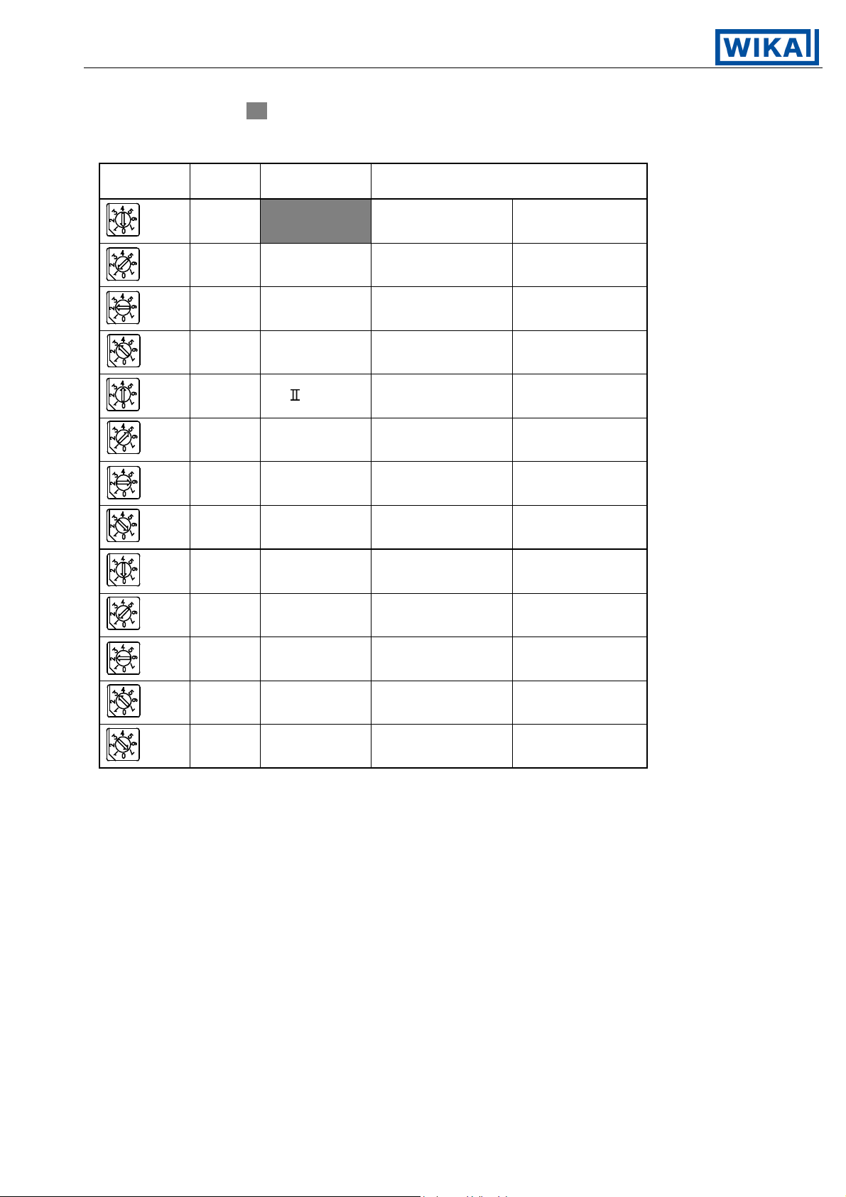
3.2 Switch setting (multi-function)
Using a small slotted screwdriver and tweezers, set the Sensor input, Alarm 1 action, Alarm 2 action,
Control action, Heating (reverse)/Cooling (direct) action, Alarm 1 and 2 standby functions, Unit °C/°F and
Program starting form Auto/Manual change by rotary switch and DIP switch by the following procedure.
The rotary switch A2 (SW301) is equipped only when the option A2 is applied.
Control action designation Alarm 2 action type designation
Heating/Cooling action designation Alarm 1 action type designation
larm 1 standby action designation Sensor input designation
larm 2 standby action designation
°C/°F designation
Sensor input designation
Program start Auto/Manual
designation
Rotary switch
DIP switch
[Fig. 3.2-1]
V1.2 • 08/2004 - 7 -
Page 8

Operating Instructions Temperature Indicating Controller CF2S
The following items can be designated by the DIP switch (SW304).
Factory adjusted as all switches OFF [
].
[Table 3.2-1]
Item
Control action
action
Sw. No.
1
and
2
3
Fuzzy self-tuning PID action No.1: OFF No.2: OFF
PID action No.1: ON No.2: OFF
PD action No.1: OFF No.2: ON
ON/OFF action No.1: ON No.2: ON
Heating (reverse) action No.3: OFFHeating/Cooling
Cooling (direct) action No.3: ON
Designation Switch status
No standby action No.4: OFFAlarm 1 (A1)
standby action
4
Standby action No.4: ON
No standby action No.5: OFFAlarm 2 (A2)
standby action
5
Standby action No.5: ON
(*1)
°C/°F 6
Sensor input
(*2)
°C No.6: OFF
°F No.6: ON
K, J, R, B, N, PL- ,
Pt100, JPt100
7
S, E, T, C,
(With decimal point)
No.7: OFF
No.7: ON
Pt100 (Without decimal point)
Manual start No.8: OFFProgram start
Auto/Manual
8
Automatic start No.8: ON
*1: The standby function will not work if the option A2 is not applied.
*2: The sensor input can be designated by the combination of this item and the rotary
switch sensor input (SW303). (See page 11.)
Program start: This item is available for the program control.
Manual start : Program starts by pressing the
key.
Automatic start : Set program is automatically started from step 1 by turning the power
supply to the instrument on (after 2 seconds of warm-up status).
V1.2 • 08/2004 - 8 -
Page 9
Operating Instructions Temperature Indicating Controller CF2S
Select the sensor type by rotary switch sensor input (SW303).
Factory adjusted as K, [
[Table 3.2-2]
].
Rotary Sw.
No.
0OFFK -200 to 1370 °C -320 to 2500 °F
1 OFF J -200 to 1000 °C -320 to 1800 °F
2 OFF R 0 to 1760 °C 0 to 3200 °F
3 OFF B 0 to 1820 °C 0 to 3300 °F
4OFF PL- 0 to 1390 °C 0 to 2500 °F
5 OFF N 0 to 1300 °C 0 to 2300 °F
6 OFF Pt100 -199.9 to 850.0 °C -199.9 to 999.9 °F
7 OFF JPt100 -199.9 to 500.0 °C -199.9 to 900.0 °F
0 ON S 0 to 1760 °C 0 to 3200 °F
DIP Sw.
No. 7
Type of
sensor
Scale range
1 ON E 0 to 1000 °C 0 to 1800 °F
2 ON T -199.9 to 400.0 °C -199.9 to 750.0 °F
3 ON C (W/Re5-26) 0 to 2315 °C 0 to 4200 °F
7 ON Pt100 -200 to 850 °C -320 to 1560 °F
V1.2 • 08/2004 - 9 -
Page 10

Operating Instructions Temperature Indicating Controller CF2S
The alarm action type and the pattern end output when program control can be
designated by the rotary switch A1 (SW302) and A2 (SW301).
The rotary switch A2 (SW301) is equipped only when the option A2 is applied.
Rotary switch A1 (SW302): Alarm 1 (A1) action or Pattern end 1 output.
Rotary switch A2 (SW301): Alarm 2 (A2) action or Pattern end 2 output.
Factory adjusted as No alarm action, [
[Table 3.2-3]
Alarm 1 action
No alarm action 0 No alarm action 0
High limit alarm 1 High limit alarm 1
Low limit alarm 2 Low limit alarm 2
High/Low limits alarm 3 High/Low limits alarm 3
Hi/Lo limit range alarm 4 Hi/Lo limit range alarm 4
Process high alarm 5 Process high alarm 5
Process low alarm 6 Process low alarm 6
A1 Rotary Sw.
(Sw302) No.
].
Alarm 2 action
A2 Rotary Sw.
(Sw301) No.
Pattern end 1 output 7 Pattern end 2 output 7
3.3 Insertion of the internal assembly
When the setup is completed, insert the internal assembly into the case.
Firmly insert the assembly until it is locked by the hook at the bottom of the instrument.
(There will be a clicking sound.)
Caution
Do not confuse the top and bottom of the internal assembly.
If inserting the assembly into the case by force in the wrong direction, the PCB
may be damaged.
V1.2 • 08/2004 - 10 -
Page 11
Operating Instructions Temperature Indicating Controller CF2S
4. Operations
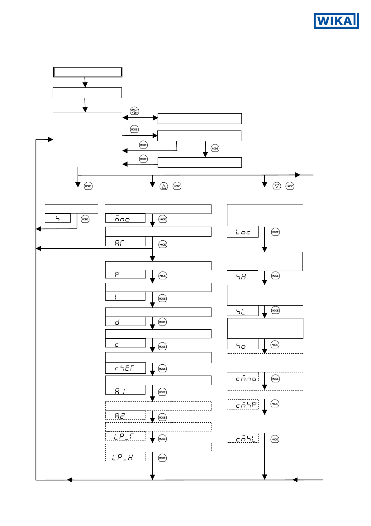
4.1 Operating flow chart
Instrument power ON
Warm-up status (For approx. 2s, displays as shown on page 15.)
1s
PV/SV display mode
+ + 3s
[Main setting mode] [Sub setting mode] [Auxiliary function setting mode 1]
Control output OFF function
3s
Output manipulating value
Step rest time *1
Main setting Setting value memory No. selection Setting value lock
PV
PV
Auto-tuning Perform/Cancel
PV
*2
designation
PV
Main setting value
Proportional band setting high limit setting
PV
Integral time setting
PV
Derivative time setting
PV
Proportional cycle setting
PV
Manual reset setting
PV
Alarm 1 (A1) setting
PV
Transfer rate selection
Alarm 2 (A2) setting
PV
setting
PV
PV
Main setting value
low limit setting
PV
Sensor correcting
value setting
PV
Instrument number
PV
Communication protocol
Loop break alarm time setting selection
PV
Loop break alarm span setting
PV
PV
V1.2 • 08/2004 - 11 -
Page 12
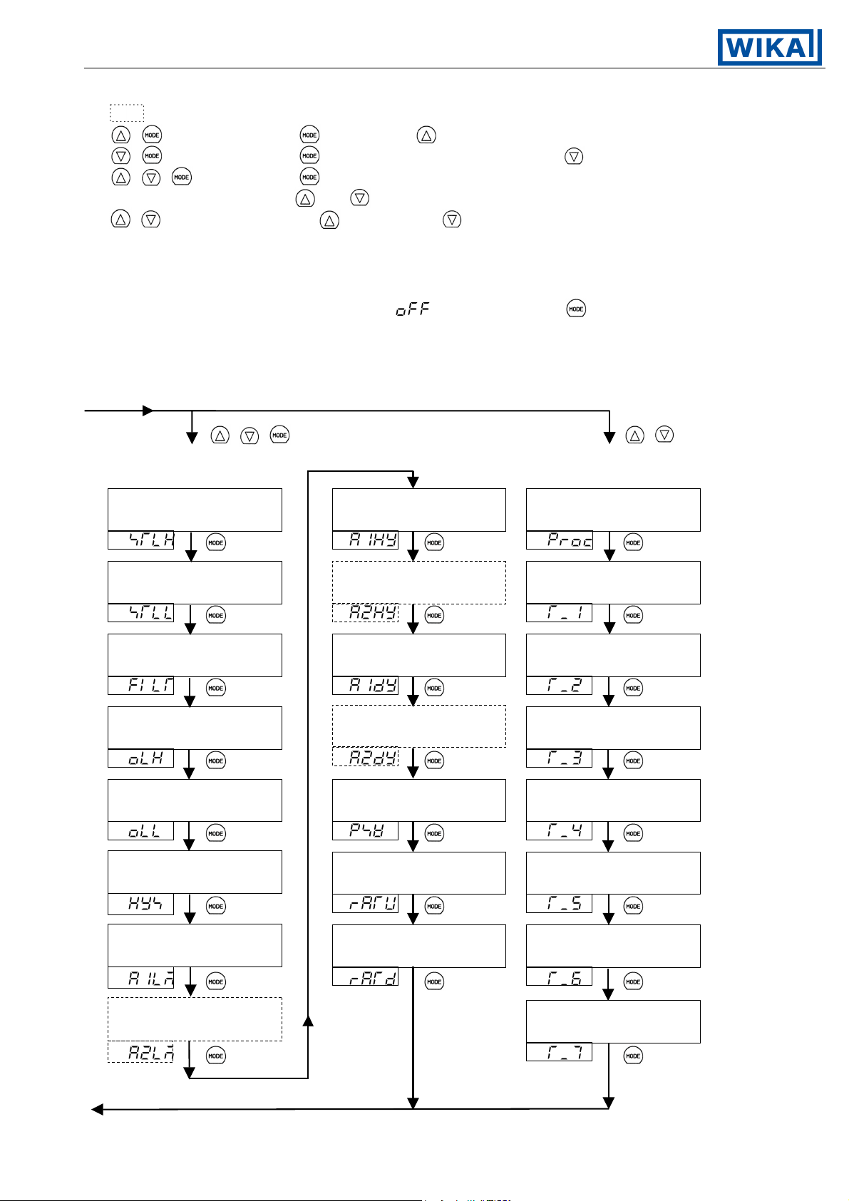
Operating Instructions Temperature Indicating Controller CF2S
: Options
+ : Press the key while the key is being pressed.
+ 3s: Press the key for approx. 3 seconds while the key is being pressed.
+ + 3s: Press the key for approx. 3 seconds
while the
and keys are being pressed.
+ 3s : Pressing the key, press the key for approx. 3 seconds.
*1: Step rest time is indicated only during program control.
*2: If the Auto-tuning is performed, the mode reverts to the PV/SV display.
If the Auto-tuning is released, the mode will move to “Proportional band setting”.
*3: In the mode Program control change, if is selected and the key is
pressed, the display reverts to the PV/SV display mode.
Set the temperature setting of program in the Sub setting mode, Auxiliary fuction
setting mode 1 and 2.
+ + 3s + 3s
[Auxiliary function setting mode 2] [Program mode]
Scaling high limit Alarm 1 (A1) hysteresis Program control change
setting setting
PV
PV
PV
Scaling low limit Alarm 2 (A2) hysteresis Step 1 time setting
setting setting
PV
PV
PV
PV filter time constant Alarm 1 (A1) action Step 2 time setting
setting delayed timer setting
PV PV
PV
Main output high limit Alarm 2 (A2) action Step 3 time setting
setting delayed timer setting
PV PV
PV
Main output low limit Display selection when Step 4 time setting
setting control output off
PV PV
PV
Main output ON/OFF Main setting value Step 5 time setting
action hysteresis setting rising rate setting
PV PV
PV
*3
Alarm 1 (A1) action Main setting value Step 6 time setting
Energized/Deenergized falling rate setting
PV
PV
PV
Alarm 2 (A2) action Step 7 time setting
Energized/Deenergized
PV PV
V1.2 • 08/2004 - 12 -
Page 13

Operating Instructions Temperature Indicating Controller CF2S
4.2 Operations
The PV display indicates the sensor type and the SV display indicates the rated value
selected by Sensor input designation (page 10, 11) for approx. 2 seconds after the power
is turned on. See [table 4.2-1].
During this time, all outputs and LED indicators are in their off status.
After that, the actual temperature is displayed on the PV display, main setting value on the SV
display and starts control.
(1) PV/SV display mode
Instrument power ON
Warm-up status (for 2s)
[Table 4.2-1] Rated value
[Table 4.2-1]
Input
PV display SV display PV display SV display
°C °F
K
J
R
B
PL-ll
N
S
E
T
C
Pt100
JPt100
Pt100
PV/SV display mode Mode during control.
Actual Main The contents of setting items nor setting values
Temperature setting value cannot be changed.
V1.2 • 08/2004 - 13 -
Page 14
Operating Instructions Temperature Indicating Controller CF2S
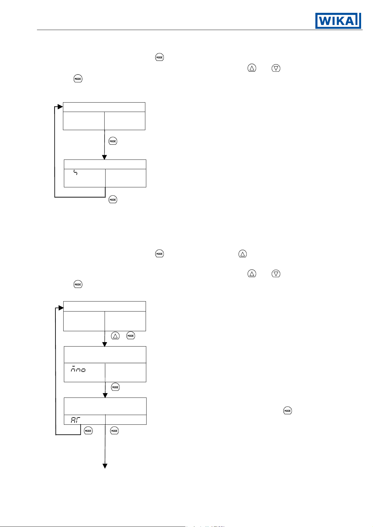
(2) Main setting mode
In the PV/SV display mode, if the
key is pressed, the Main setting mode will be selected.
The setting value can be increased or decreased by pressing the and keys.
If the
key is pressed, the setting value will be registered and the controller will
revert to the PV/SV display.
PV/SV display mode
Actual Main setting
Temperature value
Main setting
Setting Mode to set the setting value of the main control.
value
Setting range: From Main setting value low limit
to Main setting value high limit
[Factory adjusted as 0°C]
(3) Sub setting mode
In the PV/SV display mode, if the
key is pressed while the key is being pressed,
Sub setting mode will be selected.
The setting value can be increased or decreased by pressing the
If the
key is pressed, the setting value is registered and the next setting item will be selected.
PV/SV display mode
and keys.
Actual Main setting
temperature value
+
Setting value memory Mode to select the memory number (file)
number selection to be set or to be called.
Selected Selecting items: 1 to 7
value [Factory adjusted as Memory number 1.]
Auto-tuning Mode to designate the auto-tuning Perform or Cancel.
Perform/Cancel If Auto-tuning Perform is designated, and the
Designation key is pressed, the controller reverts to PV/SV display mode.
(When Perform) To set the other values, cancel the Auto-tuning.
When the ON/OFF action or PD action is selected in the
Control action designation (page 10), this display is not available.
V1.2 • 08/2004 - 14 -
Page 15

Operating Instructions Temperature Indicating Controller CF2S
SV
(Auto-tuning Cancel)
SV
If the Auto-tuning is released during the process,
Proportional band setting Mode to set the proportional band.
Setting value Setting range: 0.1 to 999.9%
Integral time setting Mode to set the integral time.
Setting value Setting range: 0 to 3600s
[Factory adjusted as 200s]
Derivative time setting Mode to set the derivative time.
Setting value Setting range: 0 to 3600s
[Factory adjusted as 50s]
(Auto-tuning Perform)
[Factory adjusted as Auto-tuning Cancel]
the PID value reverts to the former value.
[Factory adjusted as 2.5%]
This display is not available when the ON/OFF action is
selected in Control action designation (page 10).
Setting the value to 0 disables the function.
This display is not available when the ON/OFF action or
PD action is selected in Control action designation (page 10).
Setting the value to 0 disables the function.
This display is not available when the ON/OFF action is
selected in Control action designation (page 10).
Proportional cycle setting Mode to set the proportional cycle
Setting value Setting range: 1 to 120s
[Factory adjusted as 30s to Relay contact output type
and 3s to Non-contact voltage output type]
This display is not available when the ON/OFF action is
selected in Control action designation (page 10).
This setting item is not available to Current output type.
With the Relay contact output type, if the proportional cycle time
is decreased, the frequency of the relay action increases, and
the life of the relay contact is shortened.
Manual reset setting Mode to set the reset value to correct the offset
Setting value (Deviation between SV and PV when equilibrium status).
Setting range: proportional band converted value
[However, in the range, –199.9 to 999.9°C (°F)]
[Factory adjusted as 0.0°C]
This display is indicated only when PD action is designated in
the Control action designation (page 10).
Manual reset setting method:
When SV>PV, set the positive + value (SV–PV).
When SV<PV, set the negative – value (SV–PV).
V1.2 • 08/2004 - 15 -
Page 16
Operating Instructions Temperature Indicating Controller CF2S
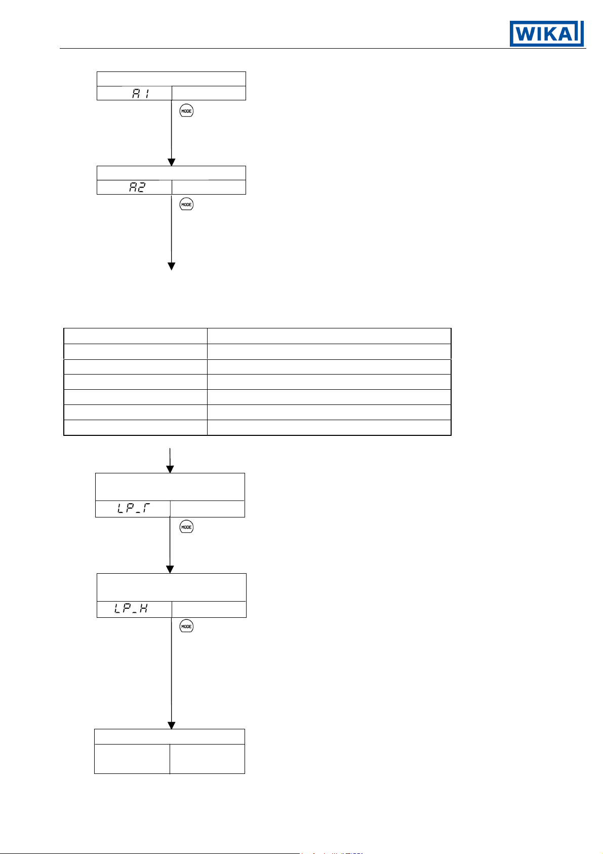
Alarm 1 (A1) setting Mode to set the action point of the Alarm 1 (A1) output.
[Factory adjusted as 0°C]
[Factory adjusted as 0°C]
Setting range of Alarm 1 and 2
(The setting range is the same when the standby function is added.)
[Table 4.2-2]
Alarm type Setting range
High limit alarm –Input span to Input span
Low limit alarm –Input span to Input span
High/Low limits alarm 1 to Input span
High/Low limit range alarm 1 to Input span
Process high alarm Input range minimum to Input range maximum
Process low alarm Input range minimum to Input range maximum
For RTD input, the minimum value of the negative side is –199.9.
Setting value
This item is not displayed if setting the rotary switch
to No. 0 or No. 7 (See page 12.)
Setting range: see [table 4.2-2].
Alarm 2 (A2) setting Mode to set the action point of the Alarm 2 (A2) output.
Setting value
This item is not displayed if the option [A2] is not
applied or even if it is applied, when setting the
rotary switch to No. 0 or No. 7 (See page 12.)
Setting range: see [table 4.2-2].
Loop break alarm Mode to set the time for Loop break alarm
time setting activation assessment.
Loop break alarm Mode to set the span for Loop Break Alarm
Actual Main setting
Temperature value
Setting value Setting range: 0 to 200 minutes
[Factory adjusted as 0 minutes.]
This display is indicated only when the option [AR] or
[AL] is applied.
span setting activation assessment.
Setting value Setting range:
0 to 150°C (Thermocouple, except T and RTD
without a decimal point)
0.0 to 150.0°C (Thermocouple T and RTD
with a decimal point)
[Factory adjusted as 0°C]
This display is indicated only when the option [AR] or
[AL] is applied.
PV/SV display mode
V1.2 • 08/2004 - 16 -
Page 17

Operating Instructions Temperature Indicating Controller CF2S
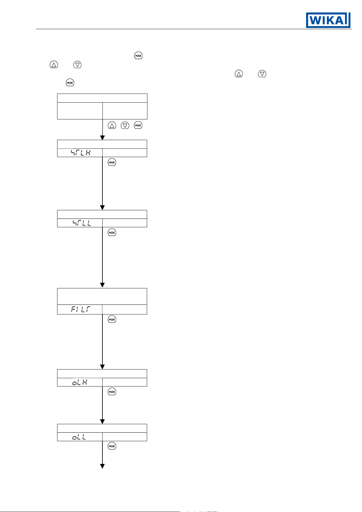
(4) Auxiliary function setting mode 1
In PV/SV display mode, if the
is being pressed, Auxiliary function setting mode 1 can be selected.
The setting value can be increased or decreased by pressing the
If the key is pressed, the setting value is registered and the next setting item is selected.
PV/SV display mode
Actual Main setting
Temperature value
+ for approx. 3s
Setting value lock Mode to lock the setting value to prevent error.
designation
Designation designation.
[Factory adjusted as Unlock status.]
key is pressed for approx. 3 seconds while the key
and keys.
The setting item to be locked depends on the
Unlock status. All setting values are changeable.
None of the setting items can be changed.
Only main setting value is changeable.
All setting items can be changed, however, the value returns
to the former value after the power off because the
value is not written on the non-volatile memory.
This mode is used when changing the value temporarily.
Fuzzy self-tuning or Auto-tuning PID action will not
function if [
When designating Lock, designate Lock 1, 2 or 3 after
setting the necessary items in the status Unlock.
As to the Lock mode 3
When using the CF2S as a Fixed value controller.
The setting values can temporarily be changed by the selected
setting value memory number, however, when the number is
changed, the setting values changed by the previous number are
canceled and returns to the former values.
When using the CF2S as a Program controller.
The setting values can temporarily be changed by the step
number performing, however, when the step number is changed,
the setting values are canceled and returns to the former values.
Setting value change is null when the controller is waiting for
running. The running starts by the values memorized.
] or [ ] is designated.
V1.2 • 08/2004 - 17 -
Page 18

Operating Instructions Temperature Indicating Controller CF2S
Main setting value Mode to set the high limit of main setting value.
high limit setting (If scaling high limit value is changed,
Setting value this setting value will be changed as well.)
Setting range: Main setting value low limit to scaling high limit value
[Factory adjusted as 400°C]
Main setting value Mode to set the low limit of main setting value.
low limit setting (If scaling low limit value is changed,
Setting value this setting value will be changed as well.)
Setting range: Scaling low limit value to main setting value high limit
[Factory adjusted as 0°C]
Sensor correction setting Mode to set the correct value of the sensor.
Setting value Setting range: –100.0 to 100.0°C
Instrument number setting Mode to set the Instrument number individually
Setting value to each instrument when communicating by
[Factory adjusted as 0.0°C]
connecting multiple instruments in serial communication.
Setting range: 0 to 95 [Factory adjusted as 0]
This display is available only when the option
[CR2] or [CR5] is applied.
Transfer rate selection Mode to select a communication transfer rate
4800bps
Selection to meet the rate of the host computer.
[Factory adjusted as 9600bps]
2400bps
9600bps
19200bps
This display is available only when the option [CR2] or [CR5] is applied.
Communication protocol Mode to select a communication protocol
selection between the CF2S and the host computer.
Selection [Factory adjusted as ]
Based on Modbus, ASCII mode
PV/SV display mode
Actual Main setting
Temperature value
V1.2 • 08/2004 - 18 -
This display is available only when the option [CR2] or [CR5] is applied.
WIKA standard protocol
Page 19
Operating Instructions Temperature Indicating Controller CF2S
(5) Auxiliary function setting mode 2
In PV/SV display mode, if the
and keys are being pressed, Auxiliary function setting mode 2 can be selected.
The setting value can be increased or decreased by pressing the
If the
PV/SV display mode
Actual Main setting
temperature value
Scaling high limit setting Mode to set the high limit value of the scaling.
key is pressed, the setting value is registered and the next setting item is selected.
+ + for approx. 3s
Setting value If scaling high limit value is changed, main setting
high limit value will be changed to the scaling
key is pressed for approx. 3 seconds while the
and keys.
high limit value as well.
Setting range: Scaling low limit value to
input range maximum value
[Factory adjusted as 1370°C]
Scaling low limit setting Mode to set the low limit value of the scaling.
PV filter time constant Mode to suppress the PV fluctuation caused by
setting such as disturbance.
[Factory adjusted as 0.0s]
Main output high limit setting Mode to set the high limit value of the main output.
Setting value If scaling low limit value is changed, main setting
low limit value will be changed to the scaling
low limit value as well.
Setting range: Input range minimum value to
scaling high limit value
[Factory adjusted as –200°C]
Setting value Set the value larger by degrees, and find the setting
value at which the value does not fluctuate.
If the value is set too large, it affects control result
due to the delay of response.
Setting range: 0.0 to 10.0s
Setting value Setting range: Main output low limit value to 105%
Setting greater than 100% is effective to the type
Current output. [Factory adjusted as 100%]
This display is not available for the ON/OFF action.
Main output low limit setting Mode to set the low limit value of the main output.
V1.2 • 08/2004 - 19 -
Setting value Setting range: –5% to Main output high limit value
Setting less than 0% is effective to the type
Current output. [Factory adjusted as 0%]
This display is not available for the ON/OFF action.
Page 20

Operating Instructions Temperature Indicating Controller CF2S
Main output ON/OFF Mode to set the ON/OFF action hysteresis of the
action hysteresis setting main control output.
Alarm 1 (A1) action Mode to select the action Energized or Deenergized
Energized/Deenergized for Alarm 1.
Setting value Setting range: 0.1 to 100.0°C
[Factory adjusted as 1.0°C]
This display is indicated only when the ON/OFF action
is designated in Control action designation (page10).
Selection [Factory adjusted as Energized]
This display is not indicated when the rotary switch is set to No. 0
or No. 7 in Alarm 1 action designation (page 12).
Energized
Deenergized
Alarm 2 (A2) action Mode to select the action Energized or Deenergized
Energized/Deenergized for Alarm 2.
Alarm 1 hysteresis setting Mode to set the hysteresis value for Alarm 1.
Selection [Factory adjusted as Energized]
This display is not indicated when the rotary switch is set to
No. 0 or No. 7 in Alarm 2 action designation (page 14), or
the option [2AS] or [2AL] is not applied.
Selection items: The same as those of the alarm 1 (A1) action
Energized/Deenergized selection.
Setting value Setting range: 0.1 to 100.0°C
[Factory adjusted as 1.0°C]
This display is not indicated when the rotary switch is set to
No. 0 or No. 7 in Alarm 1 action designation (page 12).
Alarm 2 hysteresis setting Mode to set the hysteresis value for Alarm 2.
V1.2 • 08/2004 - 20 -
Setting value Setting range: 0.1 to 100.0°C
[Factory adjusted as 1.0°C]
This display is not indicated when the option [2AS] or [2AL]
is not applied and when the rotary switch is set to No. 0
or No. 7 in Alarm 2 action designation (page 12) even
if the option [2AS] or [2AL] is applied.
Page 21

Operating Instructions Temperature Indicating Controller CF2S
Alarm 1 (A1) action Mode to set the action delayed timer for Alarm 1.
delayed timer setting Setting range: 0 to 9999s
Alarm 2 (A2) action Mode to set the action delayed timer for Alarm 2.
delayed timer setting Setting range: 0 to 9999s
Setting value [Factory adjusted as 0s]
Alarm output is turned on when the setting time has passed
after the input gets into the alarm output range.
This display is not indicated if the rotary switch is set to
No. 0 or No. 7 in Alarm 1 action designation (page 12).
Setting value [Factory adjusted as 0s]
Alarm output is turned on when the setting time has passed
after the input gets into the alarm output range.
This display is not indicated when the option [2AS] or [2AL] is
not applied and when the rotary switch is set to No. 0 or
No. 7 in Alarm 2 action designation even if the option [2AS]
or [2AL] is applied (P.12).
Display selection when Mode to select the display when the control output
control output is off is off.
OFF is indicated on the PV display.
Selection [Factory adjusted as indicating OFF on the PV display]
No indication (all unlit).
Only PV is indicated.
Main setting value Mode to set the rising rate of the main setting
rising rate setting value. (Rising value per minute)
Main setting value Mode to set the falling rate of the main setting
falling rate setting value. (Falling value per minute)
Setting value Setting the value to 0 or 0.0 disables the function.
Setting range:
0 to 9999°C /min. Thermocouple, except T and RTD without a decimal point
0.0 to 999.9°C /min. Thermocouple T and RTD with a decimal point
[Factory adjusted as 0°C /min.]
Setting value Setting the value to 0 or 0.0 disables the function.
Setting range:
0 to 9999°C /min. Thermocouple, except T and RTD without a decimal point
0.0 to 999.9°C /min. Thermocouple T and RTD with a decimal point
[Factory adjusted as 0°C /min.]
PV/SV display mode
Actual Main setting
temperature value
V1.2 • 08/2004 - 21 -
Page 22
Operating Instructions Temperature Indicating Controller CF2S
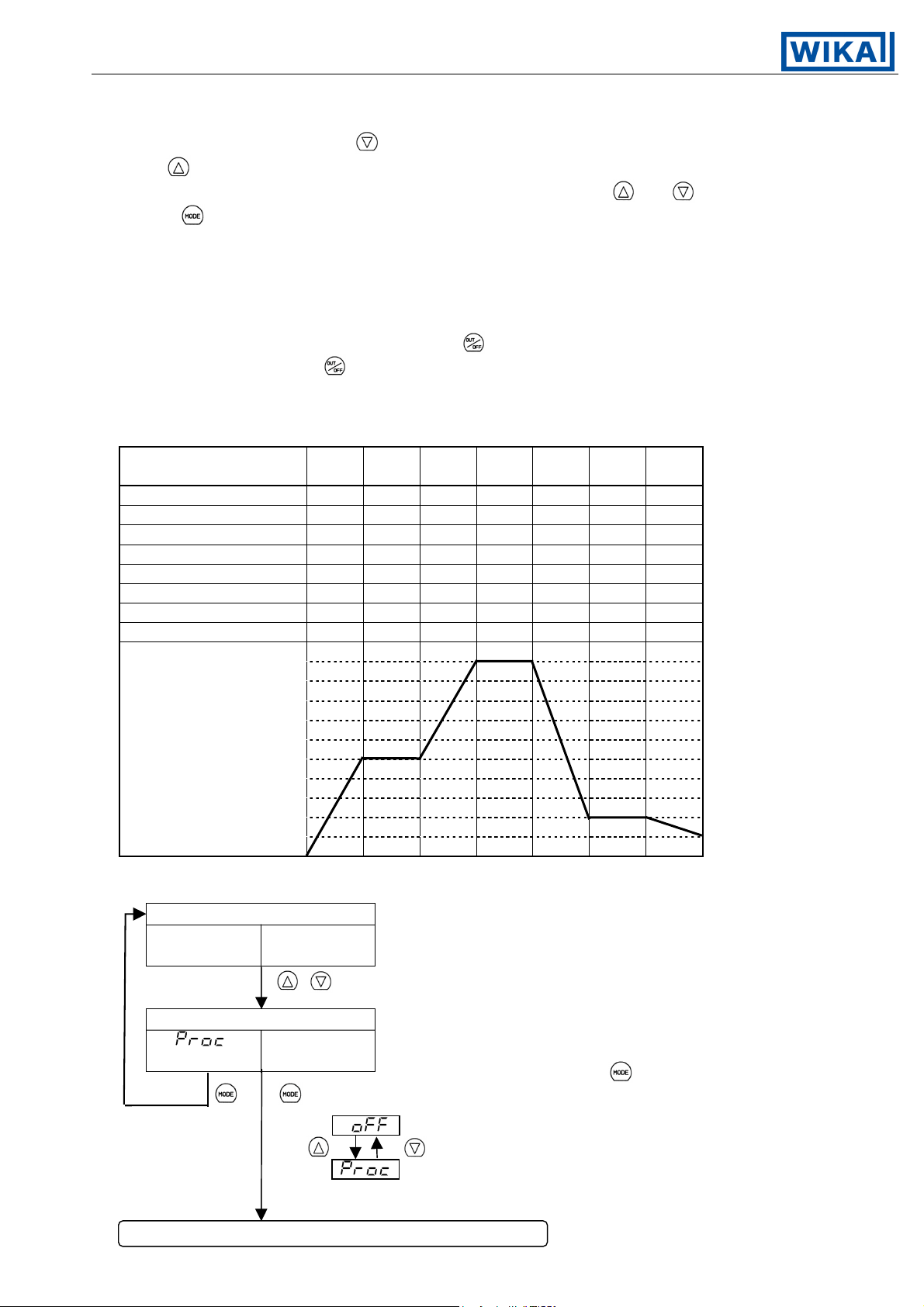
(6) Program mode
In PV/SV display mode, if the
the
key is being pressed, the Program mode can be selected.
key is pressed for approximately 3 seconds while
The setting value can be increased or decreased by pressing the and keys.
If the
key is pressed, the setting value is registered and the next setting item is selected.
As to the setting values of the step 1 to 7, each setting value for setting value memory
number 1 to 7 set during the Fixed value control is assigned respectively. For example,
values in memory number 1 are assigned to the values for step 1, and number 2 for step 2.
If the Pattern end output is designated and the program control is performed,
the Pattern end output is turned on when the program is completed.
When the Pattern end output is on and if the
output is turned off. If the
key is pressed again, the program will be performed.
key is pressed, the Pattern end
If some steps are unnecesary, set the times 00.00 for the step numbers not used.
Program Example
Step number (Setting
value memory number)
1234567
Main setting value 500 500 1000 1000 200 200 100
Proportional band 2.0 1.8 2.0 1.8 2.5 1.8 2.0
Integral time 180 80 180 80 200 80 200
Derivative time 30 20 30 20 50 20 50
Proportional cycle 30 30 30 30 30 30 30
Alarm 1 2 5 2 5 10 0 5
Alarm 2 2 5 2 5 10 0 5
Step time 00:30 01:00 00:40 01:00 02:00 00:30 01:00
1000
500
0
PV/SV display mode
Actual Main setting
temperature value
+ for approx. 3s
Program control change Control form is changed between Fixed value and Program.
Setting value of
fixed value control
In Fixed value control, if the key is pressed,
(Fixed value control)
the mode will revert to the PV/SV display.
Fixed value control
Program control
[Factory adjusted as Fixed value control]
Following display is available only when Program control.
V1.2 • 08/2004 - 22 -
Page 23
Operating Instructions Temperature Indicating Controller CF2S
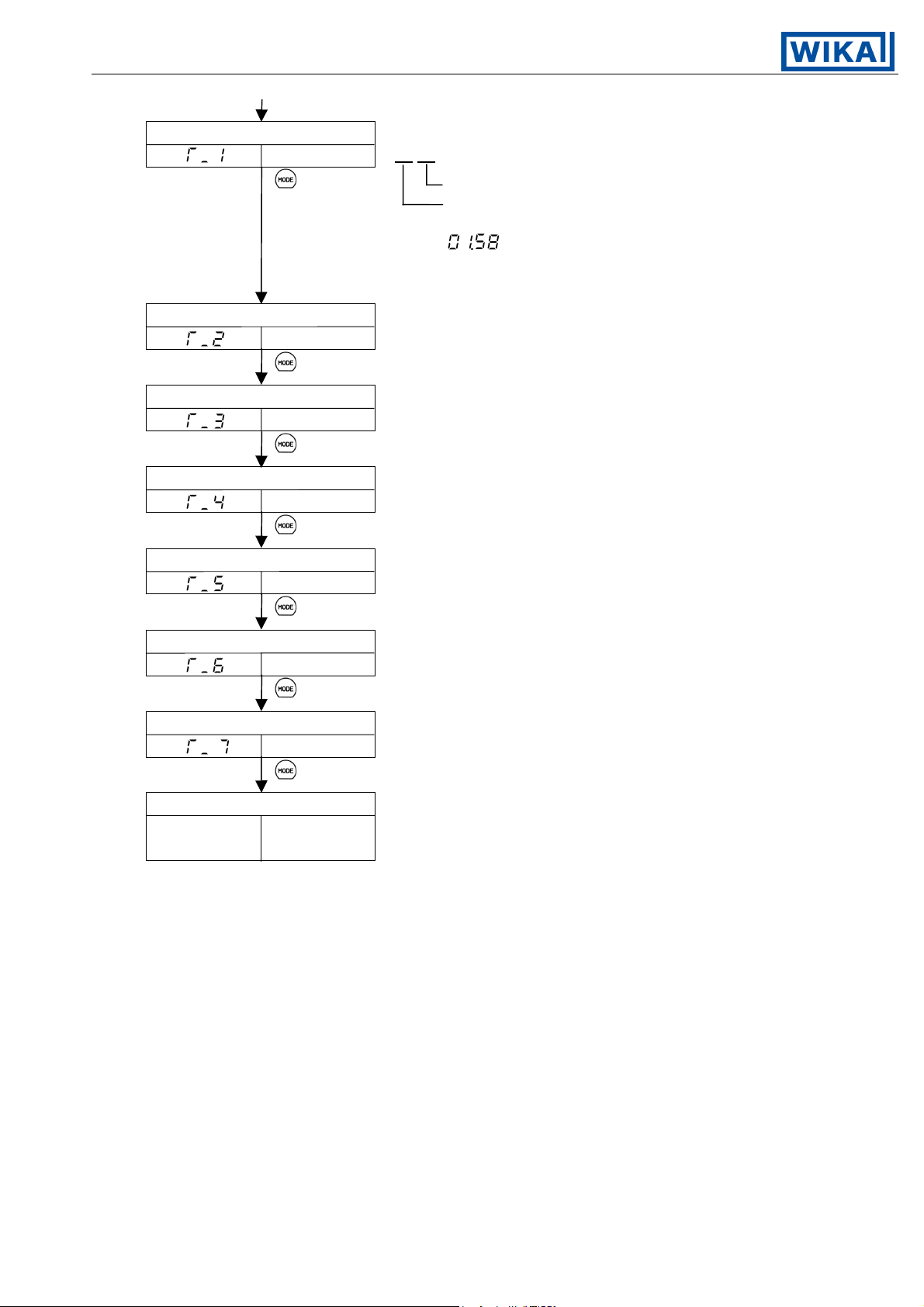
Step 1 Time setting Mode to set the Time for step 1.
Setting value 00.00
Minute indication
Hour indication
For example, when setting 1 hour 58 minutes,
set as [
Setting range: 00.00 to 99.59
[Factory adjusted as 00.00]
Step 2 Time setting Mode to set the Time for step 2.
Setting value [The setting range and the factory adjusted value
are the same as Step 1.]
Step 3 Time setting Mode to set the Time for step 3.
Setting value [The setting range and the factory adjusted value
are the same as Step 1.]
Step 4 Time setting Mode to set the Time for step 4.
Setting value [The setting range and the factory adjusted value
are the same as Step 1.]
].
Step 5 Time setting Mode to set the Time for step 5.
Setting value [The setting range and the factory adjusted value
are the same as Step 1.]
Step 6 Time setting Mode to set the Time for step 6.
Setting value [The setting range and the factory adjusted value
are the same as Step 1.]
Step 7 Time setting Mode to set the Time for step 7.
Setting value [The setting range and the factory adjusted value
are the same as Step 1.]
PV/SV display mode
Actual Main setting
temperature value
V1.2 • 08/2004 - 23 -
Page 24

Operating Instructions Temperature Indicating Controller CF2S
(7) Control output OFF function
A function to turn the control output OFF even if the power to the instrument is supplied.
The function is used when required to halt the control action or when the CF2S is not
being used in multiple controllers.
Control output OFF function can be selected from any mode by pressing the
for approx. 1 second.
The display is the same as when [Display selection when control output is off] is selected.
(See page 26.)
PV/SV display mode
Actual Main setting
temperature value
key
Control output OFF function
(*) [Unlit]
for approx. 1s [From any mode, as an example]
1s Manual reset setting
for approx. 1s
(*): PV display indicates [OFF indication], [No indication] or [Only PV]
selected in Display selection when control output is off (page 26).
Notice
Once the Control output OFF function is enabled, the function cannot be released
even if the power to the instrument is turned OFF and turned ON again.
To cancel the function, press the
In the program control, the Control output OFF function cannot be used because
the
key functions as Program Start/Stop key.
key again for approx. 1 second.
Setting value
V1.2 • 08/2004 - 24 -
Page 25

Operating Instructions Temperature Indicating Controller CF2S
(8) Output manipulating value and Step rest time indication mode
In the PV/SV display mode, press the
key for approx. 3 seconds.
The display will be changed to main setting mode in the process, however, keep
pressing it until the Output manipulating value is displayed.
If the
During program control, if the
key is pressed again, the mode reverts to the PV/SV display.
key is pressed in Output manipulating value
indication, the Step rest time indication will be selected.
If the
key is pressed again, the mode reverts to the PV/SV display.
PV/SV display mode
Actual Main setting
temperature value
for approx. 3s
Output manipulating
value indication mode
Actual manipulating Manipulating value is indicated on the SV display
temperature value by the blinking of the decimal point.
(Fixed value control) (Program control)
Step rest time indication
Actual Step Step rest time is indicated on the SV display.
temperature rest time
5. Setting value memory number external selection [Option code: SM2]
If the option [SM2] is applied, setting value memory number 2 can be selected by external operation.
The option [SM2] cannot be applied in combination with option [2AS], [2AR], [2AL], [CR2] or [CR5].
● Wiring connection of setting value memory number external selection
1
3( )
2 7
3
4
2(NC)
1( )
6
(Color of wire: Red)
NC
8
9
(Color of wire: Blue) 1
3
2
5
10
The Setting value memory number 2 can be selected by shorting between 1 and 3.
If Setting value memory number 2 is selected by the Open collector, connect the
pin No.1 to the collector and the pin No. 3 to the emitter.
When the Setting value memory number 2 is selected by external operation,
the number cannot be selected by front key operation.
Memory number cannot be changed during setting mode or PID auto-tuning.
V1.2 • 08/2004 - 25 -
Page 26

Operating Instructions Temperature Indicating Controller CF2S
6. Running
After the controller has been mounted to the control panel and wiring is
completed, it can be started in the following manner.
6.1 When using the CF2S as a Temperature controller
(1) Turn the power supply to the CF2S ON.
For approx. 2s after the power is switched ON, the type of sensor and the unit designated
in Sensor input designation (page 11) will be indicated on the PV display, and the rated
maximum value will be indicated on the SV display. See [table 6.1-1].
During this time, all outputs and LED indicators are in their OFF status.
After that, the display turns to the PV/SV display.
When the Control output OFF function is working, the item selected in the
[Display selection when control output is off] is displayed on the PV display.
(See page 26.)
[Table 6.1-1]
Input
K
J
R
B
PL-ll
N
S
E
T
C
Pt100
JPt100
Pt100
PV display SV display PV display SV display
°C °F
(2) Input the setting value, referring to Chapter 4. Operations (page 13ff).
When controlling by Fuzzy self-tuning PID action, designate [Perform] in the
Auto-tuning Perform/Cancel function to start the control in optimum conditions.
(3) Turn the load circuit power ON.
Starts the control action so as to keep the controlled object at the main setting value.
6.2 When using the CF2S as a Simplified program controller
(1) Turn the power supply to the CF2S ON.
For approx. 2s after the power is turned ON, the type of sensor and the unit designated in
Sensor input designation (page 11) are indicated on the PV display, and the rated maximum
value is indicated on the SV display. See [table 6.1-1].
During this time, all outputs and LED indicators are in their OFF status.
After that, the display reverts to the PV/SV display.
When the Control output OFF function is working, the item selected in Display
selection when control output is off is displayed on the PV display. (See page 26.)
(2) Input each setting value and each step time referring to Chapter 4. Operations (page 13ff).
Then the PV display will indicate the actual temperature and the status turns standby.
V1.2 • 08/2004 - 26 -
Page 27

Operating Instructions Temperature Indicating Controller CF2S
(3) Turn the load circuit power ON.
(4) Program control start
If Automatic start is designated in the Program start Auto/Manual designation (page 10), it will
switch to warm-up status for approx. 2 seconds after the power is turned on, and then will
automatically start the program control from step 1.
If Manual start is designated in Program start Auto/Manual designation (page 10), it will switch
to warm-up status for approx. 2 seconds after the power is turned on, and then it reverts to
standby status. In this status, if the
key is pressed, it starts the program control from the step 1.
While the program control is being performed, the change of Step number (Setting value
memory number) is ineffective.
To end the program control during the process.
The program control is ended if the key is pressed for approx. 1 second or longer.
To change the displays.
In the PV/SV display, if the key is pressed for approximately 3 seconds, the Output
manipulating value display mode is activated, and if the
key is pressed again, the
Step rest time display will be indicated (see page 29.).
Instrument status when power failure is restored.
When power is restored after a power failure occurs during program control,
the CF2S performs the program continuously.
The PV display blinks until the step at which the power failure occurs is finished.
7. Action explanations
7.1 Standard action
Action Heating (reverse) action
Control
action
Output
ON
OFF
6
7
Relay contact
6
12Vdc
Non-contact
7
voltage
+
Cooling (direct) action
Proportional band
Setting
6
7
(*1) (*1)
+
6
12/0Vdc
7
(*1)
6
7
6
0Vdc
7
+
6
7
6
0Vdc
7
+
Proportional band
Setting
6
7
+
6
0/12Vdc
7
(*1)
6
7
6
12Vdc
7
ON
OFF
+
Indicator
[OUT] Green
20mAdc
Current
6
7
Lit
+
+
6
20 to 4mAdc
7
(*2)
6
4mAdc
7
Unlit
+
(*1) Cycle action is performed according to deviation.
(*2) Changes continuously according to deviation.
V1.2 • 08/2004 - 27 -
6
4mAdc
7
+
+
6
4 to 20mAdc
7
(*2)
+
6
20mAdc
7
LitUnlit
Page 28

Operating Instructions Temperature Indicating Controller CF2S
7.2 ON/OFF action
Action Heating (reverse) action
Hysteresis
Control
action
Output
ON
OFF
6
7
Relay contact
6
12Vdc
7
Non-contact
voltage
6
20mAdc
Current
7
Main setting
+
+
6
7
6
0Vdc
7
6
4mAdc
7
Cooling (direct) action
Hysteresis
ON
OFF
Main setting
6
7
+
+
+
6
0Vdc
7
+
6
4mAdc
7
6
7
+
6
12Vdc
7
+
6
20mAdc
7
Indicator
[OUT] Green
Lit
Unlit
: Either ON or OFF
7.3 Pattern end action
Program control end
ON
OFF
[Time]
Pattern end output is
released by pressing
the key.
3
4
Unlit
Pattern end output is turned ON when the program control is ended, and it is
not released until the key is pressed.
LitUnlit
3
4
Lit
3
4
Unlit
V1.2 • 08/2004 - 28 -
Page 29

Operating Instructions Temperature Indicating Controller CF2S
7.4 Alarm 1 (A1) and 2 (A2) actions
High limit alarm
Hysteresis
Low limit alarm
Hysteresis
Temperature
alarm action
Output
Indication
Temperature
alarm action
Output
Indication
Temperature
alarm action
ON
OFF
Main
setting
3
4
Unlit
High limit alarm with standby
ON
OFF
Main
setting
3
4
Unlit
High/Low limits alarm
ON
OFF
Alarm
setting
Alarm
setting
Hysteresis
Alarm
setting
Hysteresis
Main
setting
3
4
Lit
3
4
Lit
Alarm
setting
ON
OFF
Alarm
setting
3
4
Lit
Low limit alarm with standby
Hysteresis
ON
OFF
Alarm
setting
3
4
Lit
High/Low limit range alarm
ON
OFF
Alarm
setting
Main
setting
3
4
Unlit
Main
setting
3
4
Unlit
Hysteresis
Main
setting
Alarm
setting
3
Output
4
Indication
Lit
3
4
Unlit
3
4
Lit
Standby function works at part.
and shows the action point of the alarm output.
Output terminals for Alarm 2: 3 – 5
V1.2 • 08/2004 - 29 -
3
4
Unlit
3
4
Lit
3
4
Unlit
Page 30

Operating Instructions Temperature Indicating Controller CF2S
Temperature
alarm action
Output
Indication
Temperature
alarm action
Output
High/Low limits alarm with standby
Hysteresis
ON
OFF
Alarm
setting
3
4
Lit
Process high alarm
ON
OFF
3
Main
setting
3
4
Unlit
Hysteresis
Alarm
setting
Alarm
setting
3
4
3
High/Low limit range alarm with standby
Hysteresis
ON
OFF
Lit
Alarm
setting
3
4
Unlit
Process low alarm
3
Main
setting
3
4
Lit
Hysteresis
Alarm
setting
Alarm
setting
3
4
Unlit
ON
OFF
3
Indication
Temperature
alarm action
Output
Indication
4
Unlit
Process high alarm with standby
Hysteresis
ON
OFF
3
4
Unlit
4
Lit
Alarm
setting
3
4
Lit
Standby function works at part.
and shows the action point of the alarm output.
Output terminals for Alarm 2: 3 – 5
4
Lit
Process low alarm with standby
Hysteresis
Alarm
setting
3
4
Lit
4
Unlit
ON
OFF
3
4
Unlit
V1.2 • 08/2004 - 30 -
Page 31

Operating Instructions Temperature Indicating Controller CF2S
8. Control actions
8.1 Fuzzy self-tuning
Fuzzy self-tuning is a function to perform a fine adjustment of PID values automatically.
The stable control can be carried out even if the conditions of the process are changed
due to things like change in types and rates of production.
(1) When the control is rising, the controller performs the control by the PID values
turned in advance.
(2) When the control result is disordered by the disturbance or a change in the process,
the controller checks the converging status, and performs a fine adjustment of PID values
if necessary.
(a) If the convergence is performed smoothly, the PID values are not changed.
(b) If the convergent speed is slow, the controller corrects the PID values
to accelerate the convergence.
(c) When overshoot is generated during the convergence, the controller corrects
the PID values so as not to generate the overshoot.
(d) When hunting is generated, the controller checks the waveform and performs
fine adjustment of PID values.
(3) The controller can be used without Fuzzy self-tuning by designating the internal switch.
(4) When using the controller for the first time, perform the PID auto-tuning or set the
proper PID values by key operation.
The instrument is always in self-tuning status itself, and when deviation is created, it starts
the tuning. Even if in Fuzzy self-tuning status, when very large hunting is caused and the
control is not stabilized, it starts auto-tuning automatically.
When the auto-tuning performance is designated by the key operation, tuning is initiated
and when the control is stabilized, the auto-tuning is released and returns to self-tuning status.
When lock mode [
or Auto-tuning PID action cannot work.
With the control system in which load fluctuation periodically occurs,
the Fuzzy self-tuning may fall into malfunction.
In such a case, use the controller with the PID auto-tuning mode.
8.2 Explanations of PID
(1) Proportional band (P)
Proportional action is the action which the control output varies in proportion to the deviation
between the setting value and the processing temperature.
If the proportional band is narrowed, even if the output changes by a slight variation of the
processing temperature, better control results can be obtained as the offset decreases.
However, if the proportional band is narrowed too much, even slight disturbances may cause
variation in the processing temperature, and control action changes to ON/OFF action and
the so called hunting phenomenon occurs.
Therefore, when the processing temperature comes to the balanced position near the setting
value and a constant temperature is maintained, the most suitable value is selected by
gradually narrowing the proportional band while observing the control results.
] or [ ] is designated, Fuzzy self-tuning
(2) Integral time (I)
Integral action is used to eliminate offset. When the integral time is shortened, the returning
speed to the setting point is quickened. However, the cycle of oscillation is also quickened
and the control becomes unstable.
(3) Derivative time (D)
Derivative action is used to restore the change in the processing temperature according to the
rate of change. It reduces the amplitude of overshoot and undershoot width.
If the derivative time is shortened, restoring value becomes small, and if the derivative time
is made longer, an excessive returning phenomenon may occur and the control system
may be oscillated.
V1.2 • 08/2004 - 31 -
Page 32

Operating Instructions Temperature Indicating Controller CF2S
8.3 PID auto-tuning of this controller
In order to decide each value of P, I, D and ARW automatically, this system makes the
controlled object’s temperature fluctuate.
(1) When the difference between setting value and processing temperature
is large when the temperature rises.
Fluctuation is applied at the temperature 1.5% of scaling span less than the setting value.
1.5% of scaling span
Setting value
Temperature
Time
Controlling action is performed
with the values set by PID
auto-tuning.
[Figure 8.3-1]
(2) When the control is stable or when control temperature is within ±1.5%
of scaling span.
Fluctuation is applied at the setting value.
Starting point of auto-tuning
Setting value
Controlling action is performed
Temperature
Time
with the values set by PID
auto-tuning.
[Figure 8.3-2]
(3) When the control temperature is 1.5% or greater of scaling span higher
than the setting value.
Fluctuation is applied at the temperature 1.5% of scaling span higher than the setting value.
1.5% of scaling span
Setting value
Temperature
Time
V1.2 • 08/2004 - 32 -
Controlling action is performed
with the values set by PID
auto-tuning.
[Figure 8.3-3]
Page 33

Operating Instructions Temperature Indicating Controller CF2S
9. Other functions
(1) Burnout alarm
(Upscale)
When the thermocouple or RTD is burnt out or the input value exceeds [Rated scale
maximum value +1% of rated scale span], the control output is turned OFF (main output
low limit value for the current output type) and the PV display blinks [
With the input RTD Pt100 (°F), if the input value is greater than 999.9, the PV display
blinks [
rated scale span].
(Downscale)
When the input value falls to [Rated scale minimum value –1% of rated scale span] or less,
the control output is turned OFF (main output low limit value for the current output type)
and the PV display blinks [
For the Thermocouple T or RTD input, if the input falls to less than –199.9, the PV display
blinks [
rated scale span].
(2) Self-diagnostic function
The CPU is monitored by a watchdog timer, and when any abnormal status is
found on the CPU, the controller is switched to warm-up status.
], however, the control is performed to [rated scale maximum value +1% of
].
], however, the control is performed to [rated scale minimum value –1% of
].
(3) Automatic cold junction temperature compensation (
This detects the temperature at the connecting terminal between thermocouple
and the instrument, and always keeps it at the same status as when the
reference junction is located at 0°C [32°F].
(4) Warm-up indication
For approximately 2 seconds after the power supply to the instrument is turned on,
the type of input and the temperature unit are indicated on the PV display, and the
maximum input rated value on the SV display.
(5) Setting value ramp function
When the main setting value is adjusted, it approaches the new setting value by the set rate
of change.
When the power is turned on, the control starts from the PV (process variable)
and approaches the main setting value by the rate of change.
Thermocouple input type)
V1.2 • 08/2004 - 33 -
Page 34

Operating Instructions Temperature Indicating Controller CF2S
10. Mounting to control panel
10.1 Site selection
This instrument is intended to be used under the following environmental
conditions (IEC61010-1): Overvoltage category
Mount the controller in a place with:
(1) A minimum of dust, and an absence of corrosive gases
(2) No flammable, explosive gases
(3) No mechanical vibrations or shocks
(4) No exposure to direct sunlight, an ambient temperature of 0 to 50°C (32 to122°F)
that does not change suddenly
(5) An ambient non-condensing humidity of 35 to 85%RH
(6) The controller away from large capacity electromagnetic switches or cables
through which large current is flowing
(7) No water, oil or chemicals or where the vapors of these substances can
come into direct contact with the unit
10.2 External dimension drawing
One-touch type mounting bracket
, Pollution degree 2
48
Screw type mounting bracket
48
10010
[Fig. 10.2-1]
10010
[Fig. 10.2-2]
44.5
44.5
59.7
10.3 Panel cutout drawing
75
0
+0.5
n x 48-3
+0.5
0
45
+0.5
45
Lateral close mounting
[Fig. 10.3-1] n: Number of units mounted
V1.2 • 08/2004 - 34 -
0
0
+0.5
45
Page 35

Operating Instructions Temperature Indicating Controller CF2S
10.4 Mounting
• When using the One-touch type mounting bracket [code: FT]
Mounting panel thickness is 1 to 3mm.
Mount one-touch mounting bracket 1
to the body in advance, and then insert
the CF2S 2 from the front of the panel.
If Soft front cover is used the mounting panel
thickness will be 1 to 2.5mm.
2
1
[Fig. 10.4-1]
• When using the Screw type mounting bracket [code: FS]
Mounting panel thickness is 1 to 15mm.
Insert the CF2S from the front of the panel.
Slot the mounting bracket to the holes at the top and bottom of the case, and screw in place.
1
Notice
As the case is made of resin, do not use excessive force while
screwing in the mounting bracket.
The torque is approximately 0.12N•m.
[Fig. 10.4-2]
V1.2 • 08/2004 - 35 -
Page 36

Operating Instructions Temperature Indicating Controller CF2S
11. Wiring connection
Warning
Turn the power supply to the instrument off before wiring or checking.
Working or touching the terminal with the power switched on may result
in an Electric Shock which could cause severe injury or death.
Moreover, the instrument must be grounded before the power supply to the
instrument is turned on.
11.1 Terminal arrangement
[Control output]
1
24Vdc
2
6
Non-contact
voltage output or
7
current output
[Control output]
6
Relay contact
output
7
A
B
9
10
RTD
B
8
TC
10
100 to 240Vac
or 24Vac
A1/P.end 1
A2/P.end 2/LA
1
2
3 8
4
5
TX (color of wire: Yellow)
RX (color of wire: Blue)
COM (color of wire: Black)
SM2
SM
C, C5
RS-485RS-232
YA ( ) (color of wire: Yellow)
YB ( ) (color of wire: Blue)
COM (color of wire: Black)
YA ( ) (color of wire: Yellow)
YB ( ) (color of wire: Blue)
COM (color of wire: Black)
[Fig. 11.1-1]
A1: Alarm 1 P. end 1: Pattern end 1
A2: Alarm 2 [2AS] P. end 2: Pattern end 2
[2AR]: Loop break alarm [2AL]: Alarm 2 and loop break alarm with common terminals
[CR2], [CR5]: Serial communication [SM2]: Setting value memory number external selection
• The terminal block of this instrument is designed to be wired from the left side.
The lead wire must be inserted from the left side of the terminal, and fastened with the terminal screw.
• Dotted lines show options, no terminal is equipped if it is not specified.
• If the Alarm 2 (pattern end 2 output) is applied with a combination of the Loop break
alarm output, the output terminal is common.
• Serial communication [CR2, CR5] cannot be applied in combination with the options
[2AS], [2AR], [2AL] and [SM2].
Alarm 2 (A2) is applied, however, it does not involve the alarm output but
provides the functions for indication and communication.
V1.2 • 08/2004 - 36 -
Page 37

Operating Instructions Temperature Indicating Controller CF2S
Notice
• Use a thermocouple and compensating lead wire according to the input
specifications of this controller.
• Use a 3-wire RTD system according to the input specifications of this controller.
• This controller has neither built-in power switch nor fuse. Therefore, it is
necessary to install them in the circuit near the external controller.
(Recommended fuse: Time-lag fuse, rated voltage 250V, rated current 2A)
• In the case of 24Vdc for power source, do not confuse the polarity.
• For the relay contact output type, use an external auxiliary electromagnetic
switch to protect the built-in relay contact.
• When wiring, keep the input wire (Thermocouple, RTD, etc.) away from AC
source and the load wire to avoid external interference.
• Use a thick wire (1.25 to 2.0mm²) for the earth ground.
n Solderless terminal
Use a solderless terminal with an insulation sleeve that fits to an M3 screw as shown
below.
3.2mm
3.2mm
5.8mm or less
5.8mm or less
V1.2 • 08/2004 - 37 -
Page 38
Operating Instructions Temperature Indicating Controller CF2S
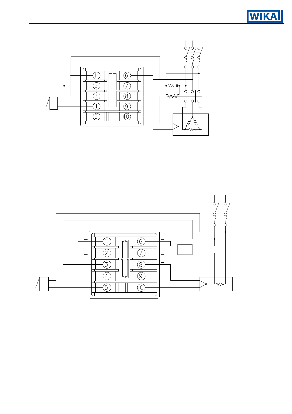
11.2 Wiring connection examples
Alarm unit (for
temperature alarm)
Thermocouple
Electric furnace
[Fig. 11.2-1]
3-phase
Heater
• To prevent the unit from harmful effects of unexpected level noise, it is recommended that
a surge absorber be installed between the electromagnetic switch coils.
Single phase
Alarm unit (for Electric furnace
temperature alarm) [Fig. 11.2-2]
• AC or DC is available to supply voltage 24V, however, do not confuse the polarity when DC is applied.
V1.2 • 08/2004 - 38 -
Page 39

Operating Instructions Temperature Indicating Controller CF2S
12. Specifications
12.1 Standard specifications
Mounting method : Flush
Setting : Input system using membrane sheet key
Display
PV display : Red LED display 4 digits, size: 8(H) x 4(W)mm
SV/MV/TIME display : Green LED display 4 digits, size: 8(H) x 4(W)mm
Indicating accuracy
Thermocouple input : Within ±0.3% of input range full scale ±1digit
however, for R or S input, the range 0 to 200°C (400°F), within ±6°C (12°F)
When B input, the range 0 to 300°C (600°F), accuracy is not guaranteed.
When K, J, T input, the range less than 0°C (32°F),
within ±0.5% of full scale ±1digit
(Cold junction compensating accuracy, ±1°C, at 0 to 50°C)
RTD input : Within ±0.3% of input range full scale ±1digit
Setting accuracy : The same as indicating accuracy
Input sampling period : 0.125 seconds
Input
Thermocouple : K, J, R, S, B, E, T [JIS, IEC], C (W/Re5-26) [ASTM],
N (IEC) and PL-ll (NBS)
External resistance, 100Ω or less
In the case of input burnout, Upscale
RTD : Pt100 (JIS, IEC), JPt100, 3-wire system
Allowable input lead wire resistance 10Ω or less per wire
In the case of input burnout, Upscale
Control output
Relay contact : 1a
Control capacity, 250Vac 3A (resistive load)
250Vac 1A (inductive load cosø=0.4)
Non-contact voltage : For SSR drive
Current : 4 to 20mA DC (Isolated type)
Load resistance, maximum 550Ω
+2
12 VDC maximum 40mA DC (short circuit protected)
0
V1.2 • 08/2004 - 39 -
Page 40

Operating Instructions Temperature Indicating Controller CF2S
Alarm 1 (A1) output
The alarm action point is set by ±deviation to main setting (except Process value alarm).
[When the alarm action is set as energized]
When the input exceeds the range, the output turns ON or OFF
(in the case of High/Low limit range alarm).
[When the alarm action is set as deenergized]
The output acts conversely.
One of the alarms can be selected by rotary switch and DIP switch from 14 types of alarm,
High limit alarm, Low limit alarm, High/Low limits alarm, High/Low limit range alarm,
Process high alarm and Process low alarm, and the standby function is applied to them
respectively, as well as No alarm and Pattern end output.
Setting accuracy : Within ±0.3% of input range full scale ±1digit
Action : ON/OFF action, Hysteresis setting range, 0.1 to 100.0°C (°F)
Output : Relay contact 1a
Control capacity 250Vac 3A (resistive load)
250Vac 1A (inductive load cosø =0.4)
(However, A1, A2 common terminal, Max. 3A)
Controlling action
The fuzzy self-tuning PID, PID, PD or ON/OFF action is selectable by DIP switch.
Fuzzy self-tuning PID action
Proportional band (P) : Automatic
Integral time (I) : Automatic
Derivative time (D) : Automatic
Anti-reset windup (ARW) : Automatic
Proportional cycle : 1 to 120s
Output limiter : 0 to 100% (In the case of Current output, –5 to 105%)
PID action (with auto-tuning function)
Proportional band (P) : 0.1 to 999.9%
Integral time (I) : 0 to 3600s (off when set to 0)
Derivative time (D) : 0 to 3600s (off when set to 0)
Anti-reset windup (ARW) : Automatic
Proportional cycle : 1 to 120s
Output limiter : 0 to 100% (In the case of Current output, –5 to 105%)
PD action
Proportional band (P) : 0.1 to 999.9%
Derivative time (D) : 0 to 3600s (Off when set to 0)
Proportional cycle : 1 to 120s
Reset : ± Proportional band converted value
Output limiter : 0 to 100% (In the case of Current output, –5 to 105%)
ON/OFF action
Hysteresis setting range : 0.1 to 100.0°C (°F)
V1.2 • 08/2004 - 40 -
Page 41

Operating Instructions Temperature Indicating Controller CF2S
Supply voltage : 100 to 240V AC 50/60Hz, 24V AC/DC 50/60Hz
Allowable voltage fluctuation : 100 to 240V AC : 85 to 264V AC
24V AC/DC : 20 to 28V AC/DC
Ambient temperature : 0 to 50°C (32 to 122°F)
Ambient humidity : 35 to 85%RH (non-condensing)
Power consumption : Approx. 8VA
Circuit insulation configuration
1
Power source
2
3
Alarm 1 (A1) output
4
Alarm 2 (A2) output
5
Option SM2 Option CR2, CR5
Isolated
CPU
Control output
(OUT)
Input
When control output is Current output type or Non-contact voltage output
type (the SSR drive), between Input and Output is non-isolated.
Insulation resistance
10MΩ or greater at 500V DC
Dielectric strength
Between input terminal and ground terminal, 1.5kV AC for 1 minute
Between input terminal and power terminal, 1.5kV AC for 1 minute
Between power terminal and ground terminal, 1.5kV AC for 1 minute
Between output terminal and ground terminal, 1.5kV AC for 1 minute
Between output terminal and power terminal, 1.5kV AC for 1 minute
Weight : Approx. 140g
External dimension : 48 x 48 x 100mm (W x H x D)
Material : Base and Case, Flame resisting resin
Color : Base and Case, black
6
7
8
9
10
Attached functions : Power failure countermeasure
Self-diagnostic function
Automatic cold junction temperature compensating function
Sensor burnout function [upscale, downscale]
Accessories : Mounting bracket 1 set
Instruction manual 1 copy
Unit nameplate 1 sheet
Wire harness CO 1 piece [When the option CR2 is applied.]
Wire harness CO
1 piece [When the option CR5 is applied.]
Wire harness C5
Terminal cover 1 piece [When the option KAB is applied.]
V1.2 • 08/2004 - 41 -
Page 42

Operating Instructions Temperature Indicating Controller CF2S
12.2 Optional specifications
Alarm 2 output [2AS]
The alarm action point is set by ±deviation to main setting (except Process value alarm).
[When the alarm action is set as energized]
When the input exceeds the range, the output turns ON or OFF
(in the case of High/Low limit range alarm).
[When the alarm action is set as deenergized]
The output acts conversely.
One of the alarms can be selected by rotary switch and DIP switch from 14 types
of alarm: High limit alarm, Low limit alarm, High/Low limits alarm, High/Low limit
range alarm, Process high alarm and Process low alarm and the standby function
is applied to them respectively, as well as No alarm and Pattern end output.
Setting accuracy : Within ±0.3% of input range full scale ±1digit
Action : ON/OFF action
Hysteresis setting range, 0.1 to 100.0°C (°F)
Output : Relay contact 1a
Control capacity, 250Vac 3A (resistive load)
250Vac 1A (inductive load cosø=0.4)
(However, A1 and A2 common terminal, Max. 3A)
Loop break alarm output [2AR]
Detects the breaking status on the loop such as heater burnout, sensor burnout or
the operation end trouble.
Output Relay contact 1a
Control capacity, 250Vac 3A (resistive load)
250Vac 1A (inductive load, cosø=0.4)
Alarm 2 output and Loop break alarm output [2AL]
When option [2AL] Alarm 2 output and Loop break alarm output is selected,
the output terminal is common.
Output Relay contact 1a
Control capacity, 250Vac 3A (resistive load)
250Vac 1A (inductive load, cosø=0.4)
Serial communication [CR2 or CR5]
The options [Code; 2AS, 2AR, 2AL and SM2] cannot be applied in combination with this option.
Alarm 2 (A2) is applied, however, it does not involve the alarm output but
provides the functions for indication and communication.
The following operations can be executed from the external computer.
(1) Reading and setting of the Main setting value, PID values and various setting values.
(2) Reading of the input value and the action status.
(3) Change of the functions.
Communication circuit Based on EIA RS-485 [Option code: CR5]
Based on EIA RS-232C [Option code: CR2]
Communication method Half-duplex communication start-stop synchronous
Data transfer rate 2400, 4800, 9600 and 19200bps
(selectable by key operation)
Data format Start bit : 1
Data bit : 7
Parity : Even parity
Stop bit : 1
Communication protocol: WIKA standard protocol or
the protocol based on Modbus (selectable by key)
(When selecting the protocol based on Modbus,
digital external setting is not available.)
V1.2 • 08/2004 - 42 -
Page 43

Operating Instructions Temperature Indicating Controller CF2S
Setting value memory number external selection [SM2]
Selects the setting value memory number (under mentioned data as one file)
by external terminal.
(Main setting value, PID values, Alarm 1 setting value, Main output high limit value,
Main output low limit value)
The options [Code: 2AS, 2AR, 2AL, CR2 or CR5] cannot be applied in combination with this option.
Data: 7
Terminal cover [KAB]
Electrical shock protecting terminal cover
Dust-proof • Drip-proof [IP4]
Dust-proof and Drip-proof specification (IP54)
Effective for only panel surface, case part is excluded.
Effective only when the control panel surface to be mounted is vertical.
[Fig. 12.2-1]
Designated specifications
Input, Scale range : Shipped as designated range.
Alarm action : Shipped as designated alarm action (A1, A2).
Control action : Shipped as designated control action.
V1.2 • 08/2004 - 43 -
Page 44

Operating Instructions Temperature Indicating Controller CF2S
13. Troubleshooting
If any malfunctions occur, refer to the following items after checking the
power supply on.
Warning
Turn the power supply to the instrument off before wiring or checking.
Working or touching the terminal with the power switched on may
result in an Electric Shock which could cause severe injury or death.
Moreover, the instrument must be grounded before the power supply to the
instrument is turned on.
<Indication>
Phenomena Presumed cause and solution
If the PV display is
indicating [
or no indication.
If [ ] is
blinking on the
PV display.
If [ ] is
blinking on the
PV display.
If indication
of PV display
is abnormal or
unstable.
]
• Control output OFF function is working.
Press the
the function. (page 31)
• Thermocouple or RTD is burnt out.
[In the case of Thermocouple]
If the input terminal between 8-10 of the
instrument is connected, and if nearby room
temperature is indicated, the instrument should be
normal and the sensor may be burnt out.
[In the case of RTD]
If approx. 100Ω of resistance is connected to the
input terminal between A-B of the instrument and
between B-B is connected, and if nearby 0°C (32°F)
is indicated, the instrument should be normal
and the sensor may be burnt out.
• Lead wire of thermocouple or RTD is not securely
mounted to the instrument terminal.
• Polarity of thermocouple or compensating lead wire
is reversed.
• Codes (A, B, B) of RTD do not agree with the
instrument terminal.
• Designation of the Sensor input is improper.
Set the Sensor input properly by the Rotary switch
(SW303) and the DIP switch (SW304).
(page 10, 11)
• Temperature unit (°C or °F ) is mistaken.
Set the unit properly by the DIP switch. (page 10)
• Sensor correcting value is unsuitable.
Set the value suitably. (page 21)
• Specification of the Thermocouple or RTD is improper.
• AC may be leaking into thermocouple or the RTD circuit.
• There may be an equipment producing an inductive
fault or noise near the controller.
key for approx. 1s to release
V1.2 • 08/2004 - 44 -
Page 45

Operating Instructions Temperature Indicating Controller CF2S
<Key operation>
Phenomena Presumed cause and solution
If it is impossible to
set various values.
If the value does
not change by the
, keys.
If the setting
indication does not
change in the rated
scale range even if
the
are pressed, and it
is impossible to set.
If it does not start
even if the
is pressed in the
Program mode.
, keys
key
• Setting value lock (mode 1 or 2) is designated.
Release the lock designation. (page 20)
• During PID auto-tuning.
Cancel the tuning if necessary. (page 16)
• Main setting value high limit or low limit may be set at
the point the value does not change.
Set it again by Auxiliary function setting mode 1.
• Step time is not set.
Set the step time. (page 29, 30)
<Control>
Phenomena Presumed cause and solution
• Thermocouple or RTD is burnt out.
[In the case of Thermocouple]
If the input terminals between 8-10 of the
instrument is connected, and if nearby room
temperature is indicated, the instrument should be
normal and sensor may be burnt out.
If process variable
(temperature) does
not rise.
If it does not
control.
(Indicates only
PV display)
If the main output
has kept its ON
status.
If the main output
has kept its OFF
status.
[In the case of RTD]
If approx. 100Ω of resistance is connected
to the input terminals between A-B of the
instrument and between B-B is connected, and
if nearby 0°C (32°F) is indicated, the instrument
should be normal and sensor may be burnt out.
• Lead wire of thermocouple or RTD is not securely
mounted to the instrument terminal.
• Program mode is selected.
If running by Program mode, press the
When performing by Fixed value control, press the
key for approx. 3s while the key is
being pressed to select the Fixed value control
mode. (page 29)
• Main output low limit value is set to 100% or greater in
Auxiliary function setting mode 2.
Set the value appropriately. (page 24)
• Main output high limit value is set to 0% or less in
Auxiliary function setting mode 2.
Set the value appropriately. (page 24)
key.
If any unexplained malfunctions occur other than the above mentioned, make
inquiries at our agency or the shop where you purchased the unit.
V1.2 • 08/2004 - 45 -
Page 46

Operating Instructions Temperature Indicating Controller CF2S
14. Character table
<Main setting mode>
Character Item Initial value Data
Main setting 0°C
<Sub setting mode>
Character Item Initial value Data
Setting value memory number 1
Auto-tuning Perform/Cancel - - - -: Cancel
Proportional band 2.5%
Integral time setting 200s
Derivative time setting 50s
Proportional cycle R/M: 30s
S/M: 3s
Manual reset setting 0.0°C
Alarm 1 setting 0°C
Alarm 2 setting 0°C
Loop break alarm time setting 0 minutes
Loop break alarm span setting 0°C
<Auxiliary function setting mode 1>
Character Item Initial value Data
Setting value lock designation - - - -: Unlock
Main setting value high limit 400°C
Main setting value low limit 0°C
Sensor correction setting 0.0°C
Instrument number setting 0
Transfer rate selection 9600bps
Communication protocol
selection
standard protocol
: WIKA
<Auxiliary function setting mode 2>
Character Item Initial value Data
Scaling high limit setting 1370°C
Scaling low limit setting -200°C
PV filter time constant 0.0 seconds
Main output high limit setting 100%
Main output low limit setting 0%
Main output ON/OFF action
1.0°C
hysteresis
Alarm 1 action Energized/Deenergized
Alarm 2 action Energized/Deenergized
: Energized
: Energized
Alarm 1 hysteresis setting 1.0°C
Alarm 2 hysteresis setting 1.0°C
Alarm 1 delayed timer setting 0 seconds
Alarm 2 delayed timer setting 0 seconds
Display selection when control
output is off
Main setting value rising rate 0°C/minute
Main setting value falling rate 0°C/minute
V1.2 • 08/2004 - 46 -
Page 47

Operating Instructions Temperature Indicating Controller CF2S
<Program mode>
Character Item Initial value Data
Program control change
Fixed value control
Step 1 time setting 00.00
Step 2 time setting 00.00
Step 3 time setting 00.00
Step 4 time setting 00.00
Step 5 time setting 00.00
Step 6 time setting 00.00
Step 7 time setting 00.00
Loop break alarm
The alarm will be activated when the process variable (PV) does not rise as much
as the span or greater within the time it takes to assess the loop break alarm
after the manipulating value has reached 100% or the output high limit value.
The alarm will also be activated when the process variable (PV) does not fall as
much value as the span or greater within the time it takes to assess loop break alarm
after the manipulating value has reached 0% or the output low limit value.
When the control action is Direct (Cooling), the alarm acts conversely.
Sensor correction function
Corrects the input value from the sensor. When a sensor cannot be set
at a location where control is desired, the sensor measuring temperature
may deviate from the temperature in the controlled location.
When controlling with multiple controllers, the accuracy of sensors have influence
on the control. Therefore, sometimes the measuring temperature (input value)
does not concur with the same setting value. In such a case, the control
can be set with desired temperature by shifting the input value of sensors.
Energized/Deenergized function
[If the alarm action energized is selected]
When the alarm output action indicator is lit, the alarm output (terminal 3-4, 3-5)
is conducted (ON). When the alarm output action indicator is unlit, the alarm output
is not conducted (OFF).
[If the alarm action deenergized is selected]
When the alarm output action indicator is lit, the alarm output (terminal 3-4, 3-5)
is not conducted (OFF). When the alarm output action indicator is unlit, the alarm
output is conducted (ON).
V1.2 • 08/2004 - 47 -
 Loading...