

Page 1

Temperature Indicating Controller, Model CF1M
Operating Instructions
WIKA Operating Instructions CF1M V1.1 • 03/2005
WIKA Alexander Wiegand GmbH & Co. KG
Alexander-Wiegand-Straße 30
63911 Klingenberg/Germany
Phone (+49) 93 72/132-0
Fax (+49) 93 72/132-406
E-Mail
www.wika.de
info@wika.de
Page 2
Operating Instructions Temperature Indicating Controller CF1M
To prevent accidents arising from the use of this controller, please ensure the operator using it receives this
manual.
Warning
Turn the power supply to the instrument OFF before wiring or checking.
Working or touching the terminal with the power switched ON may result in Electric Shock,
which can cause severe injury or death.
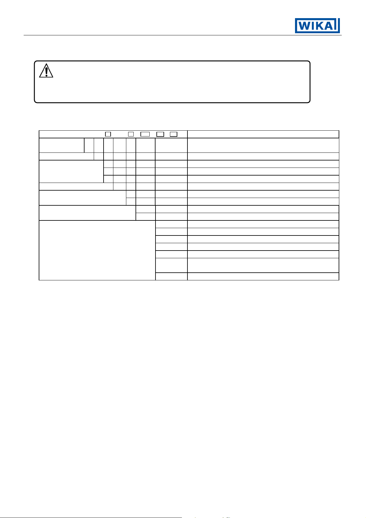
1. Model names
CF1M - 3 A / M - - - Series name CF1M
Control
characteristic
Alarm A Multi alarm, output open collector
Control output
Input M Multi-function input (input configuration setable)
Options
3 PID (setable control parameter)
R Relay
S Logic level (DC 0/12 V) for solid state relay
A Analogue current signal (4 ... 20 mA)
H AC 100 ... 240 V, 50 ... 60 HzPower supply
L AC/DC 24 V
B Factory adjustmentInstrument configuration
# (?) To customers specification
CR5 Serial communication RS 485
W10 Heater burnout alarm for 1 phase (max. 5 A)
W11 Heater burnout alarm for 1 phase (max. 10 A)
W12 Heater burnout alarm for 1 phase (max. 20 A)
W15 Heater burnout alarm for 1 phase (max. 50 A)
SV2 Parameter memory for 2 set values, external
selectable by connection terminals
KAB Terminal cover
The options [CR5], [W1X] and [SV2] cannot be applied together. (Only one option can be applied.)
V1.1
03/2005 - 2 -
•
Page 3
Operating Instructions Temperature Indicating Controller CF1M
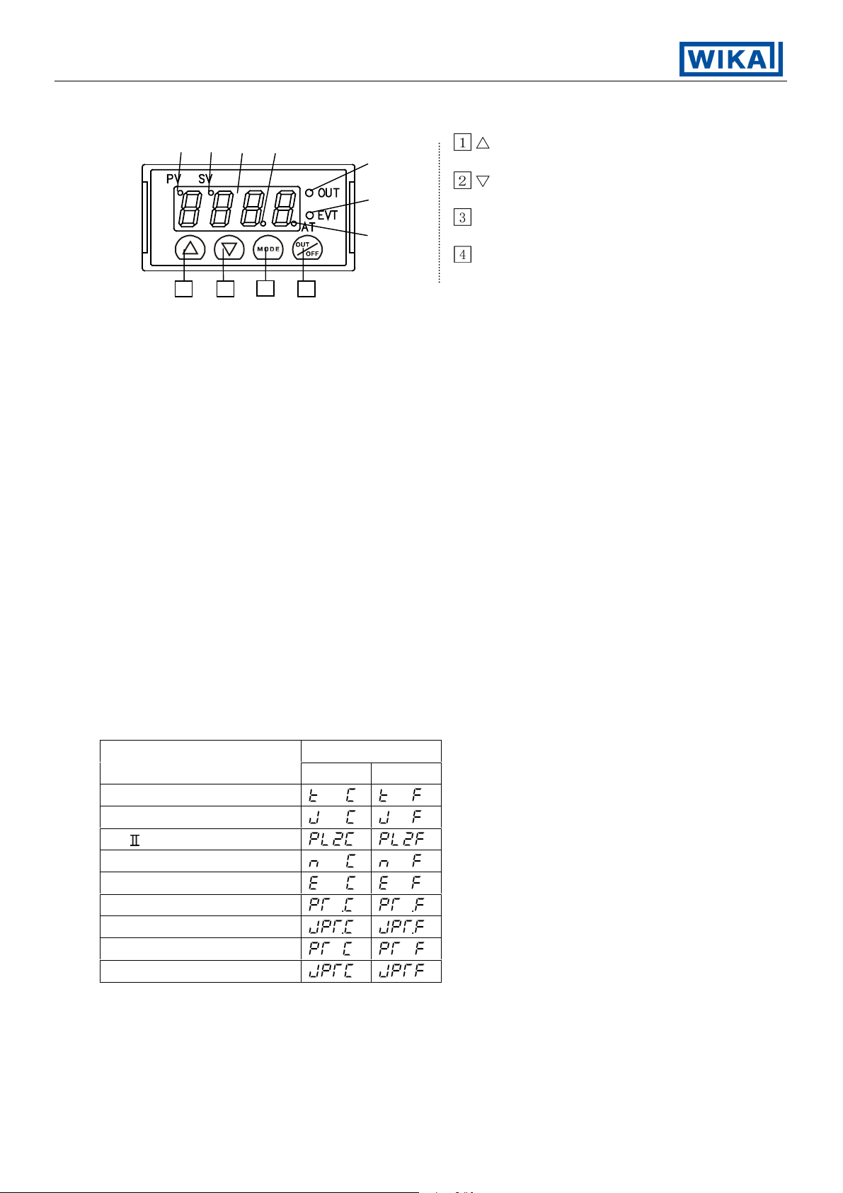
2. Name and functions of the section
(1) (2) (3) (4)
key : Increases the
(5) numeric value.
key : Decreases the
(6) numeric value.
MODE key : Selects the
(7) setting mode.
OUT
/
key : Turns the control
OFF
output ON or OFF.
1 2 3 4
(1) PV indicator : The red LED lights up while Process variable is being indicated on the PV/SV display.
(2) SV indicator : The red LED lights up while Setting value is being indicated on the PV/SV display.
It blinks while being controlled with the main setting 2.
(3) PV/SV display : Indicates the process variable, setting value and characters with red LED.
(4) Decimal point : The red LED lights up when decimal point is applied to the setting value.
indicator It blinks when Manipulating value (MV) is being displayed.
(5) Control output : The green LED lights up when the control output is ON.
indicator
(6) Event output : The red LED lights up when the Temperature alarm, Loop break alarm or
indicator Heater burnout alarm is ON.
(7) Auto-tuning : The red LED blinks while the Auto-tuning or Auto-reset is being performed.
action indicator
3. Operation
PV/SV display indicates the characters of the sensor type and temperature unit for approx.
2 seconds after the power is turned on. During this time, all outputs and the LED indicators are
in their off status. (Refer to table 3.1-1 and 3.1-2.)
After that, actual temperature or the main setting value is indicated, and control starts.
(If PV display is selected in PV/SV display selection, the actual temperature will be indicated.
If SV display is selected, the main setting value will be indicated.)
[Table 3.1-1]
Input
PV/SV display
°C °F
K
J
PL-
N
E
Pt100 (With decimal point)
JPt100 (With decimal point)
Pt100
JPt100
V1.1
03/2005 - 3 -
•
Page 4

Operating Instructions Temperature Indicating Controller CF1M
3.1 Operation flow chart
PV/SV display mode
(Approx. 3s)
+ + (Approx. 3s) + + (Approx. 3s)
(Approx. 1s)
[Main setting mode] [Sub setting mode] [Auxiliary function setting mode 1] [Auxiliary function setting mode 2]
Main setting 1
[ ]
Main setting 2
[
]
AT Perform/Cancel or
Auto reset Perform
[ / ]
Proportional band value setting
[ ]
Integral time setting
[
]
Derivative time setting
[
]
Proportional cycle setting
[
]
Temperature alarm setting
[
]
Heater burnout alarm output
setting [
]
Loop break alarm time setting
]
[
Loop break alarm action span
setting [
]
Control output OFF function
[ ]
PV/SV display change
[ ]
Setting value lock designation
[ ]
Main setting value high limit
setting [ ]
Main setting value low limit
setting [ ]
Sensor correction setting
[ ]
Instrument number setting
[ ]
Transfer rate setting
[ ]
Output manipulating value display
Sensor selection
[
]
PV filter time constant setting
[
]
Output high limit setting
[ ]
Output low limit setting
[ ]
Output ON/OFF hysteresis
setting [ ]
Event output function selection
[
]
Temperature alarm action
selection [ ]
Temperature alarm energized/
deenergized selection [ ]
Temperature alarm hysteresis
setting [ ]
Temperature alarm delayed
timer setting [
]
Main setting value rising rate
setting [
]
Main setting value falling rate
+ : Press the key while the key is being pressed.
+ (Approx. 3s): Press the key for 3 seconds while the
key is being pressed.
+ + (Approx. 3s): Press the key for 3 seconds while
the
and key are being pressed.
setting [
Output Direct/Reverse change
[
]
Auto-tuning bias setting
[
]
The functions with dashed frames are optional
and not active for every controller !
V1.1
03/2005 - 4 -
•
]
Page 5

Operating Instructions Temperature Indicating Controller CF1M
3.2 Main setting mode
Character Name, Description, Setting range Initial
Main setting 1
• Sets Main setting value 1 of the main control.
• Main setting low limit value to Main setting high limit value
Main setting 2
• Sets Main setting value 2 of the main control.
• This setting item is available only when the option [SV2] is applied.
• Main setting low limit value to Main setting high limit value
3.3 Sub setting mode
Character Name, Description, Setting range Initial
Auto-tuning Perform/Cancel, or Auto-reset Perform
• Designates auto-tuning performance or
or auto-reset performance.
• Auto-reset will be canceled automatically in approx. 4 minutes.
Proportional band value setting
• Sets the proportional band of control output.
• Setting the value to 0 or 0.0, control output acts ON/OFF.
• 0 (0.0) to rated scale maximum value
Integral time setting
• Sets the integral time of control output.
• Setting the value to 0 disables the function.
• With PD action (I=0), auto-reset can be performed.
• 0 to 3600 seconds
Derivative time setting
• Sets the derivative time of control output.
• Setting the value to 0 disables the function.
• 0 to 3600 seconds
Proportional cycle setting
• Sets the proportional cycle value.
• This setting item is not available when ON/OFF action or current
output type is selected.
• 1 to 120 seconds
Temperature alarm setting
• Sets the action point of the temperature alarm output.
• This setting item is not available if no alarm action is selected in
Temperature alarm action selection.
• This setting item is available only when the “Temperature alarm output
function” is selected in “Event output function selection”.
• Refer to the Table 3.3-1.
Heater burnout alarm setting
• Sets the current value of Heater burnout alarm.
• This setting item is available only when the option [W1X] is applied.
• This setting item is available only when the “Heater burnout alarm” is
selected in “Event output function selection”.
• Self-holding is not available to the alarm output.
• In the case of 5A, 0.0 to 5.0A
In the case of 10A, 0.0 to 10.0A
In the case of 20A, 0.0 to 20.0A
In the case of 50A, 0.0 to 50.0A
cancellation,
0°C (°F)
0°C (°F)
Cancel
10°C
(20°F)
200s
50s
R/M : 30s
S/M : 3s
0°C (°F)
0.0A
V1.1
03/2005 - 5 -
•
Page 6

Operating Instructions Temperature Indicating Controller CF1M
Loop break alarm action time setting
• Sets the time it takes to assess the Loop break alarm.
• This setting item is available only when the “Loop break alarm” is
selected in “Event output function selection”.
• 0 to 200 minutes
Loop break alarm action span setting
• Sets the span to assess the Loop break alarm.
• This setting item is available only when the “Loop break alarm” is
selected in “Event output function selection”.
• 0 to 150°C (°F), or 0.0 to 150.0°C (°F)
[Table 3.3-1]
Alarm action type Setting range
High limit alarm -Input range span to input range span -199.9 to input range span
Low limit alarm -Input range span to input range span -199.9 to input range span
High/Low limits alarm 0 to input range span 0.0 to input range span
High/Low limit range alarm 0 to input range span 0.0 to input range span
Process high alarm
Process low alarm
High limit alarm w/standby -Input range span to input range span -199.9 to input range span
Low limit alarm w/standby -Input range span to input range span -199.9 to input range span
High/Low limits w/standby 0 to input range span 0.0 to input range span
Hi/Lo limit range w/standby 0 to input range span 0.0 to input range span
Process high alarm
with standby
Process low alarm
with standby
Input range minimum to
input range maximum
Input range minimum to
input range maximum
Input range minimum to
input range maximum
Input range minimum to
input range maximum
Input range minimum to
input range maximum
Input range minimum to
input range maximum
Input range minimum to
input range maximum
Input range minimum to
input range maximum
Setting range
(with decimal point)
0 min.
0°C (°F)
3.4 Auxiliary function setting mode 1
Character Name, Description, Setting range Initial
PV/SV display change
• Changes the display PV (
Setting value lock designation
• Locks the setting value to prevent error.
The setting item to be locked depends on the designation.
• PID auto-tuning or auto-reset will not function if Lock 1 or Lock 2
is designated.
•
Main setting value high limit setting
(Unlock): All setting values can be changed.
(Lock 1): None of the setting values can be changed.
(Lock 2): Only main setting value is changeable.
(Lock 3): All setting values can be changed,
• Sets the high limit value of main setting.
• Main setting low limit to input range maximum
Main setting value low limit setting
• Sets the low limit value of main setting.
• Input range minimum to main setting high limit
) or SV ( ).
however, they revert to their former values
after the power is turned off because they
are not stored in the non-volatile memory.
PV
display
Unlock
°C
1370
0°C
V1.1
03/2005 - 6 -
•
Page 7

Operating Instructions Temperature Indicating Controller CF1M
Sensor correction setting
• Sets sensor correction value.
• -100.0 to 100.0°C (°F)
Instrument number setting
• Sets the Instrument number individually to each instrument when
communicating by connecting multiple instruments in serial communication.
• This setting item is available only when the option [CR5] is applied.
• 0 to 95
Transfer rate setting
• Selects the communication transfer rate to meet the rate of the
host computer.
• This setting item is available only when the option [CR5] is applied.
• 2400bps:
4800bps:
9600bps:
19200bps:
3.5 Auxiliary function setting mode 2
Character Name, Description, Setting range Initial
Sensor selection
• Input type and unit (°C or °F) can be chosen from 5 types of
thermocouple and 4 types of RTD.
Multi-range input type
K 0 to 1370°C :
J 0 to 1000°C :
PL- 0 to 1390°C :
N 0 to 1300°C :
E 0 to 800°C :
Pt100 -199.9 to 850.0°C :
JPt100 -199.9 to 500.0°C :
Pt100 -200 to 850°C :
JPt100 -200 to 500°C :
K 0 to 2500°F :
J 0 to 1800°F :
PL- 0 to 2500°F :
N 0 to 2300°F :
E 0 to 1500°F :
Pt100 -199.9 to 999.9°F :
JPt100 -199.9 to 900.0°F :
Pt100 -300 to 1500°F :
JPt100 -300 to 900°F :
0.0°C (°F)
0
9600bps
K
PV filter time constant setting
• Sets PV filter time constant value.
If the value is set too large, it affects control result due to the delay
of response.
• 0.0 to 10.0 seconds.
Output high limit setting
• Sets output high limit value.
• This setting item is not available for the ON/OFF action.
• -5 to 105% (Setting greater than 100% is effective to the type Current
output only.)
Output low limit setting
• Sets output low limit value.
• This setting item is not available for the ON/OFF action.
• -5 to 105% (Setting less than 0% is effective to the type Current
output only.)
V1.1
03/2005 - 7 -
•
0.0s
100%
0%
Page 8

Operating Instructions Temperature Indicating Controller CF1M
Output ON/OFF action hysteresis setting
• Sets the ON/OFF action hysteresis of control output.
• This setting item is available only for the ON/OFF action.
• 0.1 to 100.0°C
Event output function selection
• One of the functions is selectable from Temperature alarm,
Loop break alarm or Heater burnout alarm.
• Heater burnout alarm can be selected only when option [W1X] is
applied.
• Temperature alarm output :
Loop break alarm output :
Heater burnout alarm output (option):
Temperature alarm action selection
• Selects temperature alarm action.
• No alarm :
High limit alarm :
High limit alarm w/standby :
Low limit alarm :
Low limit alarm w/standby :
High/Low limits alarm :
High/Low limits alarm w/standby :
High/Low limit range alarm :
High/Low limit range alarm w/standby :
Process high alarm :
Process high alarm w/standby :
Process low alarm :
Process low alarm w/standby :
Temperature alarm energized/deenergized selection
• Sets the temperature alarm output as energized or deenergized.
• This setting item is not available if Temperature alarm output
is not selected in Event output function selection, nor if No alarm is
selected in Temperature alarm action selection.
• Energized :
Deenergized :
Temperature alarm hysteresis setting
• Sets hysteresis value for temperature alarm.
• This setting item is not available if Temperature alarm output is not
selected in Event output function selection, nor if No alarm is selected
in Temperature alarm action selection.
• 0.1 to 100.0°C (°F)
Temperature alarm delayed timer setting
• Sets the action delayed timer for temperature alarm.
Alarm output works past the setting time after the input value
reaches the alarm output range.
• This setting item is not available if Temperature alarm output is not
selected in Event output function selection, nor if No alarm action
is selected in Temperature alarm action selection.
• 0 to 9999 seconds
Main setting value rising rate setting
• Sets the rising rate of main setting value. (Rising value per minute)
• 0 to 9999°C /min. (°F /min.)
With decimal point, 0.0 to 999.9°C /min. (°F /min.)
Main setting value falling rate setting
• Sets the falling rate of main setting value. (Falling value per minute)
• 0 to 9999°C /min. (°F /min.)
With decimal point, 0.0 to 999.9°C /min. (°F /min.)
1.0°C
No alarm
Energized
1.0°C (°F)
0s
0°C /min.
0°C /min.
V1.1
03/2005 - 8 -
•
Page 9

Operating Instructions Temperature Indicating Controller CF1M
Output Direct/Reverse change
• Changes the output action Reverse (Heating) or Direct (Cooling).
• Reverse (Heating) action:
Reverse
(Heating)
action
Direct (Cooling) action :
Auto-tuning bias setting
• Sets PID auto-tuning bias value.
20°C
(40°F)
• 0 to 50°C (0 to 100°F)
With decimal point, 0.0 to 50.0°C (0.0 to 100.0°F)
Sensor correction function
Corrects the input value from the sensor. When a sensor cannot be set at a location
where control is desired, the sensor measuring temperature may deviate from the
temperature in the controlled location. When controlling with plural controllers,
the accuracy of sensors affects the control.
Therefore, sometimes the measuring temperature (input value) does not concur with the
same setting value. In such a case, the control can be set with the desired temperature
by shifting the input value of sensors.
Loop break alarm
After the manipulating value has reached 100% or output high limit value, if the process variable (PV)
has not risen at least as high as the span value by the time it takes to assess the loop break alarm,
the alarm will be activated.
After the manipulating value has reached 0% or output low limit value, if the process variable (PV)
has not fallen at least as low as the value of the span within the time it takes to assess the loop break
alarm, the alarm will also be activated.
When the control action is Direct (Cooling), the alarm acts conversely.
Energized/Deenergized
When the status of temperature alarm action is selected energized, event output
(between terminal 11 and 12) is conducted (ON) status while the event output
indicator is lit. Event output is not conducted (OFF) status while the event output
indicator is not lit.
When the status of temperature alarm action is selected deenergized, event output
(between terminal 11 and 12) is not conducted (OFF) status while the event output
indicator is lit. Event output is conducted (ON) status while the event output
indicator is not lit.
ON
OFF
Main Alarm setting Main Alarm setting
setting setting
In the case of high limit alarm In the case of high limit alarm
(energized status) (deenergized status)
Hysteresis Hysteresis
ON
OFF
Setting value memory function
If the option [SV2] is applied, the setting value memory number can be selected by
external operation. (However, selectable setting value memory number is No. 2 only.)
To select the setting value memory number 2, connect the terminals between 8 and 9.
Memory number cannot be changed during setting mode and PID auto-tuning.
V1.1
03/2005 - 9 -
•
Page 10

Operating Instructions Temperature Indicating Controller CF1M
3.6 Control output OFF function
Character Name, Descriptions
Control output OFF function
• This is the function to switch the control output OFF even if power is supplied to the
instrument.
The function is used when required to halt the control action or the CF1M
is not used in multiple controllers.
" is indicated on the PV/SV display.
"
• This function can be selected from any mode or any setting item by pressing
OUT
/
the
key for approx. 1 second.
OFF
• Once the function is working, it cannot be released even if the power
to the instrument is turned OFF and ON again.
OUT
/
To cancel the function, press the
key again for approx. 1 second.
OFF
3.7 Output manipulating value display
Character Name, Descriptions
Output manipulating value display
• In the PV/SV display mode, press the
MODE key for approx. 3 seconds.
The display will be changed to main setting mode during the process,
however, keep pressing until the output manipulating value is displayed.
(Manipulating value is indicated on the PV/SV display blinking the decimal point.)
MODE key is pressed again, the mode will revert to the PV/SV display.
If the
4. Running
After the completion of the mounting to the control panel and wiring connections,
start running in the following manner.
(1) Turn the power supplied to the CF1M ON
For approx. 2 seconds after the power is switched ON, the type of sensor is indicated on the
PV/SV display. (Refer to table 3.1-1 and 3.1-2.)
During this time, all outputs and LED indicators are in their OFF status.
After that, the PV/SV display indicates actual temperature.
If SV display is selected in PV/SV display change, the setting value will be indicated.
In the status the Control output OFF function is working, it indicates"
(2) Input the setting value
Referring to Chapter 3. Operation, input each setting value.
(3) Turn the load circuit power ON.
Starts the control action so as to keep the controlled object at the main setting value.
5. Other functions
(1) Input burnout
[Upscale]
When the thermocouple or RTD is burnt out or the input value rises to the [Rated scale maximum
value + 50°C (100°F)] or greater, the control output is turned off, and [
on the PV/SV display.
However, when the rated scale maximum value is 999.9, if the input value exceeds 999.9,
[
] blinks on the PV/SV display, and the control is performed to 999.9 + 1% of rated scale span.
[Downscale]
In the case of thermocouple input, if the input value falls to -50°C (-100°F) or less, the control output
is turned off, and [ ] blinks on the PV/SV display.
In the case of RTD input, if the input value falls to the [Rated scale minimum value - 1% of rated
scale span] or less, the control output is turned off, and [ ] blinks on the PV/SV display.
However, when the rated scale minimum value is -199.9, if the input value falls to -199.9 or less,
[
] blinks on the PV/SV display, and the control is performed to -199.9 - 1% of rated
scale span.
Even in SV display mode, the indication of [
] in upscale and of [ ] in downscale
have priority over all displays.
" on the PV/SV display.
] blinks
V1.1
03/2005 - 10 -
•
Page 11

Operating Instructions Temperature Indicating Controller CF1M
(2) Self-diagnostic function
The CPU is monitored by a watchdog timer, and when any abnormal status is found on the CPU,
the controller is switched to warm-up status.
(3) Automatic cold junction temperature compensation (thermocouple input type)
Detects the temperature at the connection terminal between thermocouple and instrument,
and always keeps it on the same status as when the reference junction is located at 0°C (32°F).
6. Action explanations
6.1 Standard action drawing
Action
Control action
Relay contact
output
Non-contact
voltage output
Current output
Heating (reverse) action Cooling (direct) action
Proportional band Proportional band
ON
OFF
3 3
4 4
Cycle action
according to deviation
+
12Vdc
3
++
20mAdc 20 to 4mAdc
4
+
12/0Vdc 0Vdc
Cycle action
according to deviation
3
Changes continuously
according to deviation
Setting Setting
3
+
+
4
3
4mAdc
3
4 4 4
according to deviation
3333
+
0Vdc
3
++
4mAdc 4 to 20mAdc 20mAdc
++
according to deviation
Changes continuously
according to deviation
3 3
Cycle action
3
0/12Vdc
44444
Cycle action
3 3
+
ON
OFF
3
12Vdc
4
44444
Indicator (OUT)
Green
part: Acts ON or OFF.
Lit
Unlit Unlit Lit
V1.1
03/2005 - 11 -
•
Page 12

Operating Instructions Temperature Indicating Controller CF1M
6.2 ON/OFF action drawing
Action Heating (reverse) action Cooling (direct) action
Hysteresis Hysteresis
Control action
Relay contact
output
Non-contact
voltage output
Current output
Indicator (OUT)
Green
ON
OFF
Setting
3
4 4
3
+
12Vdc
4
3
Lit Unlit LitUnlit
+
3
3
4
3
4mAdc
44
++
++
3
4
3
4
3
4mAdc 20mAdc
4
0Vdc
Setting
3
4
3
+
4
+
3
20mAdc
4
ON
OFF
12Vdc 0Vdc
part: Acts ON or OFF.
V1.1
03/2005 - 12 -
•
Page 13

Operating Instructions Temperature Indicating Controller CF1M
6.3 Alarm action drawings
High limit alarm action
Hysteresis
Low limit alarm action
Hysteresis
High/Low limits alarm action
Hysteresis
Alarm action
Output
Indicator
Alarm action
Output
Indicator
Alarm action
ON
OFF
Main setting
value
11
12 12
Unlit LitLit
High/Low limit range alarm action
ON
OFF
Main setting
11
12
11
12
High limit alarm with standby
ON
ON
OFF
Main setting
value
11
11 11
12
12
Unlit
ON
OFF
11
12
Lit Unlit Lit
Process high alarm action
Hysteresis Hysteresis Hysteresis
ON
OFF
ON
OFF
value
1111
12
Lit
UnlitUnlit
12
11
Low limit alarm with standby
11
1212
LitLit
High/Low limits alarm with standby
HysteresisHysteresis
ON
ON
Main setting
value
11
12
Process low alarm action
11
12
Hysteresis
11
12
UnlitUnlit
Output
Indicator
ON
Alarm action
OFF
Output
Indicator
part: Acts ON or OFF.
part: The standby functions.
OFF
Main setting
value
11
12 12
Unlit
OFF
11
Lit Unlit
11
12
Lit
Main setting
value
11
12
OFF
Main setting
value
11
12
Lit
11
12
Unlit
High/Low limit range alarm with standby Process high alarm with standby Process low alarm with standby
Hysteresis
ON
OFF
Main setting
value
11
12
Unlit
11
1212
Lit
Unlit
1111
12
Hysteresis Hysteresis
11
12
Unlit
Lit
ON
OFF
11
12
11
12
Lit
11
12
Lit
Unlit
V1.1
03/2005 - 13 -
•
Page 14

Operating Instructions Temperature Indicating Controller CF1M
6.4 Heater burnout alarm drawing
ON
11
11
OFF
Setting
Small LargeLoad current
12
Lit
12
Unlit
7. PID auto-tuning of the CF1M
In order to decide each value of P, I, D and ARW automatically, this system forcibly fluctuates
the object being controlled.
h When the difference between setting value and processing temperature is large when
the temperature rises.
Fluctuation is given at the temperature 20°C (°F) lower than the setting value.
Temperature 20 ( ) lower than the setting value
Temperature
Setting value
4
C
F
PID parameter measuring
1
PID parameter calculated point
2
Controlling action is performed
3
with the parameters set by autotuning.
AT bias setting value4
AT
h When the control is stable
Fluctuation is given at the setting value.
Temperature
Setting value
AT
Time
1
2
2
3
1
2
3
Time
31
:
Auto-tuning starting point
AT
PID parameter measuring
PID parameter calculated point
Controlling action is performed
with the parameters set by autotuning.
Auto-tuning starting point
:AT
V1.1
03/2005 - 14 -
•
Page 15

Operating Instructions Temperature Indicating Controller CF1M
h When the difference between setting value and processing temperature is large when
the temperature falls.
Fluctuation is given at the temperature 20°C (°F) or higher than the setting value.
Temperature 20 ( ) higher than the setting valueC F
Temperature
Setting value
4
AT
1
2
Time
3
PID parameter measuring
1
2
PID parameter calculated point
Controlling action is performed
3
with the parameters set by autotuning.
AT bias setting value
4
AT
8. Mounting to the control panel
8.1 Site selection
Mount the controller in a place with:
(1) A minimum of dust, and an absence of corrosive gases.
(2) No mechanical vibrations or shocks.
(3) No exposure to direct sunlight, an ambient temperature of 0 to 50°C (32 to122°F)
that does not change suddenly.
(4) An ambient non-condensing humidity of 35 to 85%RH or less.
(5) The controller away from large capacity electromagnetic switches or cables
through which large current is flowing.
(6) No water, oil or chemicals or where the vapors of these substances can
come into direct contact with the unit.
:
Auto-tuning starting point
8.2 External dimension drawing
Packing B
24
48
9.5
Mounting frame Terminal cover
[Fig. 8.2-1]
47.3
98.5
101.1
44.8
47.5
21.6
23.8
29.9
V1.1
03/2005 - 15 -
•
Page 16

Operating Instructions Temperature Indicating Controller CF1M
8.3 Panel cutout drawing
+0.6
45
0
0
+0.3
22.2
40
60
[Fig. 8.3-1]
8.4 CT (current transformer) dimension drawing
8.5 Mounting
Mounting panel thickness is from 1 to 10mm.
Insert the CF1M from the front of the panel.
Insert the mounting frame as shown in
[Fig. 8.5-1] until the four tips of
the frame touch the front panel.
CTL-6-S (5A, 10A, 20A) CTL-12-S36-10L1 (50A)
[Fig. 8.5-1]
V1.1
03/2005 - 16 -
•
Page 17

Operating Instructions Temperature Indicating Controller CF1M
9. Terminal arrangement
Warning
Turn the power supply to the instrument OFF before wiring or checking.
Working or touching the terminal with the power switched ON may result in an Electric Shock
which could cause severe injury or death.
YA(-) YB(+)
COM
Event
output
Option W1X (CT input)
or option SV2
R/ : Relay contact output
S/ : Non-contact voltage output
10
7
B Option CR5
98
11 12
9
8
A/ : Current output
SV2 : Setting value memory
(external selection)
W1X : Heater burnout alarm
AB R/
1 2
543
6
Event : Temperature alarm,
output Loop break alarm or
Heater burnout alarm output
RTD
S/ A/or
TC
100 to 240Vac
or 24Vac/dc
431 2
Dotted line: Option (Designation required)
[Fig. 9-1]
Notices
• Use a thermocouple and compensating lead wire according to the input specifications of this
controller.
• Use a 3-wire system of RTD according to the input specifications of this controller.
• This controller has no built-in power switch nor fuse. It is necessary to install them manually
(IEC approved, 100Vac 5A, 220Vac 5A) in the circuit near the external controller.
• In the case of 24Vdc, do not confuse the polarity.
• With the relay contact output type, use an external auxiliary electromagnetic switch to protect
the built-in relay contact.
• When wiring, keep input wire (Thermocouple, RTD, etc.) away from AC source and load wire
to avoid external interference.
n Recommended terminal
Use a solderless terminal with an insulation sleeve that fits to M3 screw as shown below.
3.2mm
5.8mm or less
V1.1
03/2005 - 17 -
•
5.8mm or less
3.2mm
Page 18

Operating Instructions Temperature Indicating Controller CF1M
Option: Heater burnout alarm output
(1) This alarm is not available for
detecting current under phase control.
(2) Use the current transformer (CT) supplied
and pass one lead wire of heater circuit
into the hole of the CT.
(3) When wiring, keep CT wire away
from AC source and load wire to
avoid external interference.
8. Specifications
8.1 Standard specifications
Mounting method : Flush
Setting : Input system by using membrane sheet key
Display : Red LED display 4 digits, size, 8(H) x 4(W)mm
Accuracy (Setting and indicating)
Thermocouple : Within ±0.3% of input range full scale ±1 digit,
or 2°C (4°F) whichever is greater
RTD : Within ±0.2% of input range full scale ±1 digit
or 1°C (2°F) whichever is greater
Scaling range
K : 0 to 1370°C (0 to 2500°F)
J : 0 to 1000°C (0 to 1800°F)
E : 0 to 800°C (0 to 1500°F)
: 0 to 1390°C (0 to 2500°F)
PLN : 0 to 1300°C (0 to 2300°F)
Pt100 : -199.9 to 850.0°C (-199.9 to 999.9°F), -200 to 850°C (-300 to 1500°F)
JPt100 : -199.9 to 500.0°C (-199.9 to 900.0°F), -200 to 500°C (-300 to 900°F)
Input sampling period: 0.25 seconds
Input
Thermocouple : K, J, E, PL-
External resistance, 100 Ω or less
When input burnout, Upscale
RTD : Pt100, JPt100 3-wire system
Allowable input lead wire resistance, 10Ω or less per wire
When input burnout, Upscale
Control output
Relay contact : 1a
Control capacity,
250Vac 3A (resistive load)
250Vac 1A (inductive load cosø=0.4)
Non-contact : For SSR drive
voltage 12
+2
, 0Vdc Maximum 40mA (short circuit protected)
Current : 4 to 20mAdc
Load resistance, maximum 500 Ω
Supply voltage : 100 to 240Vac, 50/60Hz, 24Vac/dc, 50/60Hz
Allowable voltage : In the case of 100 to 240Vac, 85 to 264Vac
fluctuation In the case of 24Vac/dc, 20 to 28Vac/dc
, N
CT
Heater
8
CT input
terminal
9
Power source
[Fig. 7-2]
V1.1
03/2005 - 18 -
•
Page 19

Operating Instructions Temperature Indicating Controller CF1M
Temperature alarm output
The alarm action point is set by ± deviation to the main setting (except Process value alarm).
[When the alarm action is set as energized]
When the input exceeds the range, the output turns ON or OFF
(in the case of High/Low limit range alarm).
[When the alarm action is set as deenergized]
The output acts conversely.
• Setting accuracy
Thermocouple : Within ±0.3% of input full scale ±1 digit, or ±2°C (4°F) whichever is greater
RTD : Within ±0.2% of input full scale ±1 digit
• Action : ON/OFF action
Hysteresis, 0.1 to 100.0°C (°F)
• Output : Open collector
Control capacity, 24Vdc 0.1A (maximum)
Loop break alarm output
When manipulating value is in its maximum or minimum status, the alarm is activated if the
process variable does not change at a rate higher than the setting span within the setting time.
Detects Heater burnout, Sensor burnout and Abnormality at operation end.
Output: Open collector
Control capacity, 24Vdc 0.1A (maximum)
Control action
PID action (with auto-tuning function)
PD action (with auto-reset function) (When I value is set to 0.)
P action (with auto-reset function) (When I and D values are set to 0.)
ON/OFF action (When P value is set to 0 or 0.0.)
Proportional band : 0 (0.0) to rated scale maximum value
Integral time : 0 to 3600s (off when set to 0)
Derivative time : 0 to 3600s (off when set to 0)
Proportional cycle : 1 to 120s
ARW : Automatic
Output limit : 0 to 100% (For the Current output type, -5 to 105%)
Hysteresis : 0.1 to 100.0°C (°F)
Circuit insulation configuration
98
Option SV2
Isolated
98
CT Input
7
98
10
11
12
Communication Event output
CPU Isolated
Input Output*
1 2
* If the control output type is current or non-contact voltage output, between
the communication and output is non-isolated.
V1.1
03/2005 - 19 -
•
Power source
543
6
Page 20

Operating Instructions Temperature Indicating Controller CF1M
Insulation resistance
10MΩ or greater at 500Vdc
In the case of the above Circuit insulation configuration (*), because the communication and output
terminals are not isolated from one another, the insulation resistance test must not be carried out.
Dielectric strength
Between input terminal and ground ---------------- 1.5kVac for 1 minute
Between input terminal and power terminal ------ .1.5kVac for 1 minute
Between power terminal and ground ---------------.1.5kVac for 1 minute
Between output terminal and ground --------------- 1.5kVac for 1 minute
Between output terminal and power terminal ----- 1.5kVac for 1 minute
Power consumption : Approx. 5VA
Ambient temperature: 0 to 50°C (32 to 122°F)
Ambient humidity : 35 to 85%RH (non-condensing)
Weight : Approx. 100g
External dimension : 48 x 24 x 98.5mm (W x H x D)
Material : Base and case, Flame resisting resin
Color : Base and case, black
Attached functions : Power failure compensating function
Self-diagnostic function
Automatic cold junction temperature compensating function
Input burnout indicating function (upscale, downscale)
Accessories : Mounting frame --------- 1 piece
Instruction manual ------.1 copy
Terminal cover -----------. 1 piece [When option KAB is applied.]
Current transformer-----.1 piece
CTL-6-S [When option W10, W11 or W12 is applied.]
CTL-12-S36-10L1 [When option W15 is applied.]
8.2 Optional functions
Serial communication [Option code: CR5]
When this option is applied, setting of the items; Temperature alarm, Heater burnout alarm
and Loop break alarm can be performed by serial communication. However, as to the
Event output, the item selected in Event output function selection has priority.
When the option [SV2] or [W1X] is applied, the option [CR5] cannot be applied together.
Following operations can be performed by the external computer.
(1) Reading and setting of the Main setting value, PID values and others
(2) Reading of input value and action status
(3) Change of the function
Communication circuit : Based on EIA RS-485 [Option: CR5]
Communication method : Half-duplex communication start-stop synchronous
Transfer rate : 2400, 4800, 9600 and 19200bps (selectable by key operation)
Data format : Start bit 1
Data bit 7
Parity Even parity
Stop bit 1
V1.1
03/2005 - 20 -
•
Page 21

Operating Instructions Temperature Indicating Controller CF1M
Heater burnout alarm [Option code: W1X]
Watches the heater current with CT (current transformer), and detects the burnout.
This option cannot be applied to the type current output.
When the option [SV2] or [CR5] is applied, the option [W1X] cannot be applied together.
Rating : 5A [Option W10], 10A [Option W11],
20A [Option W12] or 50A [Option W15]
Setting range : In the case of 5A, 0.0 to 5.0A (off when set to 0.0)
In the case of 10A, 0.0 to 10.0A (off when set to 0.0)
In the case of 20A, 0.0 to 20.0A (off when set to 0.0)
In the case of 50A, 0.0 to 50.0A (off when set to 0.0)
Setting accuracy: ±5%
Input resolution : 1/200 of each rated value
Action : ON/OFF action
Output : Open collector
Control capacity, 24Vdc 0.1A (maximum)
Setting value memory (external selection) [Option code: SV2]
If this option is applied, the main setting value 1 or 2 can be changed by the external contact.
When the option [W1X] or [CR5] is applied, the option [SV2] cannot be added together.
When the contact open : Main setting 1
When the contact closed : Main setting 2
Terminal cover [Option code: KAB]
Electrical shock protecting terminal cover
9. Troubleshooting
When troubled, refer to the following items after checking the power and the wiring.
<Indication>
Phenomenon Presumed cause and the action
If PV/SV display is
indicating [ ]
If [ ] is blinking
on the PV/SV display
• Control output OFF function is working.
Press the
OUT
/
key for approx. 1s to release the function.
OFF
• Thermocouple or RTD is burnt out.
[In the case of Thermocouple]
If the input terminal of the instrument is connected,
and if nearby room temperature is indicated, the instrument
should be normal and sensor may be burnout.
[In the case of RTD]
If approx. 100Ω of resistance is connected to the input terminal
between A-B of the instrument and between B-B is connected,
and if nearby 0°C (32°F) is indicated, the instrument should
be normal and sensor may be burnout.
• Lead wire of thermocouple or RTD is not surely mounted to the
instrument terminal.
If [ ] is blinking
on the PV/SV display
If indication of
PV/SV display is
abnormal or unstable.
• Polarity of thermocouple or compensating lead wire is reverse.
• Codes (A, B, B) of RTD does not agree with the instrument terminal.
• Designation of the Sensor input is improper.
• Temperature unit (°C or °F) is mistaken.
• Sensor correcting value is unsuitable.
Set the value suitably.
• Specification of the Thermocouple or RTD is improper.
• AC leaks into thermocouple or RTD circuit.
• There is a piece of equipment to send out inductive interference
or noise near the controller.
V1.1
03/2005 - 21 -
•
Page 22

Operating Instructions Temperature Indicating Controller CF1M
<Key operation>
Phenomenon Presumed cause and the action
If it is impossible to set.
If the value does
not change by the
, keys.
If the setting
indication does not
change in the rated
scale range even if
, keys
the
are pressed, and
setting is impossible.
<Control>
Phenomenon Presumed cause and the action
If process variable
(temperature) does
not rise.
If the main output
remains ON status.
If the main output
remains OFF status.
• Setting value lock (mode 1 or 2) is designated.
Release the lock designation.
• During PID auto-tuning or auto-reset.
In the case of PID auto-tuning, cancel the tuning if necessary.
In the case of Auto-reset, it takes approx. 4 minutes
until the auto-reset is completed.
• Main setting value high limit or low limit may be set at the point
the value does not change.
Set it again by Auxiliary function setting mode 1.
• Thermocouple or RTD is burnt out.
• Lead wire of thermocouple or RTD is not securely mounted to the
instrument terminal.
• confirm the connection of the output is securely carried out.
• Main output low limit setting value is set to 100% or greater
in Auxiliary function setting mode 2.
Set the value properly.
• Main output high limit setting value is set to 0% or less
in Auxiliary function setting mode 2.
Set the value properly.
If any unexplained malfunctions occur other than the above mentioned, make inquiries at our agency
or the shop where you purchased the unit.
V1.1
03/2005 - 22 -
•
 Loading...