

Page 1

Operating instructions
Betriebsanleitung
EN
DE
Documenting multi-function calibrator, model CEP6100
Dokumentierender Multifunktionskalibrator, Typ CEP6100
Documenting multi-function calibrator, model CEP6100
Page 2

2
14120028.01 04/2015 EN/DE
WIKA operating instructions model CEP6100
EN
DE
Operating instructions model CEP6100 Page 3 - 68
Betriebsanleitung Typ CEP6100 Seite 69 - 135
© 2015 WIKA Alexander Wiegand SE & Co. KG
All rights reserved. / Alle Rechte vorbehalten.
WIKA
®
is a registered trademark in various countries.
WIKA
®
ist eine geschützte Marke in verschiedenen Ländern.
Prior to starting any work, read the operating instructions!
Keep for later use!
Vor Beginn aller Arbeiten Betriebsanleitung lesen!
Zum späteren Gebrauch aufbewahren!
Page 3

3
WIKA operating instructions model CEP6100
14120028.01 04/2015 EN/DE
EN
Contents
Contents
1. General information 5
2. Short overview 6
2.1 Overview . . . . . . . . . . . . . . . . . . . . . . . . 6
2.2 Description . . . . . . . . . . . . . . . . . . . . . . . . 7
2.3 Scope of delivery . . . . . . . . . . . . . . . . . . . . . . 7
3. Safety 8
3.1 Explanation of symbols. . . . . . . . . . . . . . . . . . . . 8
3.2 Intended use . . . . . . . . . . . . . . . . . . . . . . . 8
3.3 Improper use . . . . . . . . . . . . . . . . . . . . . . . 9
3.4 Responsibility of the operator. . . . . . . . . . . . . . . . . . 9
3.5 Personnel qualification . . . . . . . . . . . . . . . . . . . . 10
3.6 Labelling, safety marks . . . . . . . . . . . . . . . . . . . . 10
4. Design and function 11
4.1 Front foil . . . . . . . . . . . . . . . . . . . . . . . . . 11
4.1.1 Connections . . . . . . . . . . . . . . . . . . . . . . 12
4.1.2 Key function . . . . . . . . . . . . . . . . . . . . . . 13
4.2 Batteries. . . . . . . . . . . . . . . . . . . . . . . . . 14
4.2.1 Selecting the batteries or rechargeable batteries . . . . . . . . . 14
4.2.2 Using the power supply unit . . . . . . . . . . . . . . . . 14
5. Transport, packaging and storage 15
5.1 Transport . . . . . . . . . . . . . . . . . . . . . . . . 15
5.2 Packaging and storage . . . . . . . . . . . . . . . . . . . . 15
6. Commissioning, operation 16
6.1 Main display . . . . . . . . . . . . . . . . . . . . . . . 17
6.2 Menu bar . . . . . . . . . . . . . . . . . . . . . . . . 18
6.2.1 “Measuring” menu function . . . . . . . . . . . . . . . . . 18
6.2.2 “Output” menu function . . . . . . . . . . . . . . . . . . 19
6.2.3 “Pulse output” menu function . . . . . . . . . . . . . . . . 19
6.2.4 “UPPER”, “LOWER” and “MORE” menu function . . . . . . . . . 19
6.2.5 “Documentation” menu function . . . . . . . . . . . . . . . 20
6.2.6 “Automatic output function” menu function. . . . . . . . . . . . 20
6.2.7 “Frequency or pulse output” menu function . . . . . . . . . . . 20
6.2.8 “Contrast” menu function . . . . . . . . . . . . . . . . . 20
6.2.9 “Automatic switch-off” menu function . . . . . . . . . . . . . 21
6.2.10 “Time” menu function . . . . . . . . . . . . . . . . . . . 21
6.2.11 “Probe-specific coefficients” menu function . . . . . . . . . . . 21
6.2.12 “ZERO” menu function . . . . . . . . . . . . . . . . . . 22
6.2.13 “Terminal emulation” menu function . . . . . . . . . . . . . . 22
6.2.14 “Parameter selection” menu function . . . . . . . . . . . . . 22
6.3 Cursor control/set-point control . . . . . . . . . . . . . . . . . 22
6.4 Using the measuring modes (lower display). . . . . . . . . . . . . 23
Page 4

4
WIKA operating instructions model CEP6100
14120028.01 04/2015 EN/DE
EN
Contents
Declarations of conformity can be found online at www.wika.com.
6.4.1 Measuring voltage and frequency . . . . . . . . . . . . . . 23
6.4.2 Measuring current (mA) . . . . . . . . . . . . . . . . . . 23
6.4.3 Measuring temperature . . . . . . . . . . . . . . . . . . 24
6.4.4 Measuring pressure . . . . . . . . . . . . . . . . . . . 26
6.5 Using the output modes (lower display) . . . . . . . . . . . . . . 28
6.5.1 Setting the output parameters 0 % and 100 % . . . . . . . . . . 28
6.5.2 Using the automatic output functions . . . . . . . . . . . . . 28
6.5.3 Current output . . . . . . . . . . . . . . . . . . . . . 29
6.5.4 Simulating a transmitter . . . . . . . . . . . . . . . . . . 30
6.5.5 Voltage output . . . . . . . . . . . . . . . . . . . . . 31
6.5.6 Frequency output . . . . . . . . . . . . . . . . . . . . 31
6.5.7 Pulse output . . . . . . . . . . . . . . . . . . . . . . 31
6.5.8 Simulating thermocouples . . . . . . . . . . . . . . . . . 32
6.5.9 Simulating resistance or resistance thermometers . . . . . . . . . 32
6.6 Using the isolated measuring modes (upper display). . . . . . . . . . 34
6.6.1 Measuring voltage (V) or current (mA) . . . . . . . . . . . . . 34
6.6.2 Measuring current with DC 24 V voltage supply . . . . . . . . . . 35
6.7 Using the upper and lower displays for test and calibration. . . . . . . . 35
6.7.1 Calibrating a display instrument . . . . . . . . . . . . . . . 35
6.7.2 Calibrating an I/P instrument . . . . . . . . . . . . . . . . 36
6.7.3 Calibrating a transmitter . . . . . . . . . . . . . . . . . . 37
6.7.4 Calibrating a pressure transmitter. . . . . . . . . . . . . . . 38
7. Document mode 38
7.1 Introduction. . . . . . . . . . . . . . . . . . . . . . . . 38
7.2 New tag “AS FOUND” test . . . . . . . . . . . . . . . . . . . 49
7.2.1 Setup . . . . . . . . . . . . . . . . . . . . . . . . 49
8. CalLOG programme 54
8.1 System requirements . . . . . . . . . . . . . . . . . . . . 54
8.2 Installation . . . . . . . . . . . . . . . . . . . . . . . . 54
8.3 Overview . . . . . . . . . . . . . . . . . . . . . . . . 54
9. Faults 55
10. Maintenance, cleaning and recalibration 56
10.1 Maintenance . . . . . . . . . . . . . . . . . . . . . . . 56
10.2 Cleaning. . . . . . . . . . . . . . . . . . . . . . . . . 56
10.3 Recalibration . . . . . . . . . . . . . . . . . . . . . . . 57
11. Dismounting, return and disposal 57
11.1 Dismounting . . . . . . . . . . . . . . . . . . . . . . . 57
11.2 Return . . . . . . . . . . . . . . . . . . . . . . . . . 57
11.3 Disposal . . . . . . . . . . . . . . . . . . . . . . . . . 58
12. Specifications 59
13. Accessories 66
Appendix: EC declaration of conformity 67
Page 5

5
WIKA operating instructions model CEP6100
14120028.01 04/2015 EN/DE
EN
1. General information
■
The model CEP6100 documenting multi-function calibrator described in these
operating instructions has been manufactured using state-of-the-art technology.
All components are subject to stringent quality and environmental criteria during
production. Our management systems are certified to ISO 9001 and ISO 14001.
■
These operating instructions contain important information on handling the instrument.
Working safely requires that all safety instructions and work instructions are observed.
■
Observe the relevant local accident prevention regulations and general safety
regulations for the instrument’s range of use.
■
The operating instructions are part of the product and must be kept in the immediate
vicinity of the instrument and readily accessible to skilled personnel at any time. Pass
the operating instructions onto the next operator or owner of the instrument.
■
Skilled personnel must have carefully read and understood the operating instructions
prior to beginning any work.
■
The general terms and conditions contained in the sales documentation shall apply.
■
Subject to technical modifications.
■
Factory calibrations / DKD/DAkkS calibrations are carried out in accordance with
international standards.
■
Further information:
- Internet address: www.wika.de / www.wika.com
- Relevant data sheet: CT 83.51
- Application consultant:
Tel.: +49 9372 132-5049
Fax: +49 9372 132-8005049
CTServiceteam@wika.com
1. General information
Page 6

6
WIKA operating instructions model CEP6100
14120028.01 04/2015 EN/DE
EN
1
2
3
1. General information / 2. Short overview
Abbreviations, definitions
RTD Resistance thermometer
TC Thermocouple
2W 2-wire measurement
Two test cables are used for the voltage supply.
The measurement signal also provides the supply current.
3W 3-wire measurement
Two test cables are used for the voltage supply.
One test cable is used for the measurement signal.
4W 4-wire measurement
Two test cables are used for the voltage supply.
Two test cables are used for the measurement signal.
CJC Cold junction compensation
2. Short overview
2.1 Overview
Display
Keypad
Connections
1
2
3
Page 7

7
WIKA operating instructions model CEP6100
14120028.01 04/2015 EN/DE
EN
2. Short overview
2.2 Description
The model CEP6100 documenting multi-function calibrator is a battery-operated handheld instrument which can measure or simulate electrical parameters.
The model CEP6100 works with different thermocouples and resistance thermometers,
among others.
Very high accuracy and diverse special functions make the instrument a user-friendly and
highly flexible calibration instrument.
2.3 Scope of delivery
■
Documenting multi-function calibrator model CEP6100
■
Operating instructions
■
Test cables, three sets (red/black)
■
3.1 calibration certificate per DIN EN 10204
■
Four AA batteries
■
Protective rubber boot
■
RS-232 interface cable
■
USB serial adapter
■
CalLOG software
■
Quick start guide
Cross-check scope of delivery with delivery note.
Page 8

8
WIKA operating instructions model CEP6100
14120028.01 04/2015 EN/DE
EN
3. Safety
3. Safety
3.1 Explanation of symbols
WARNING!
... indicates a potentially dangerous situation that can result in serious
injury or death, if not avoided.
CAUTION!
... indicates a potentially dangerous situation that can result in light injuries
or damage to equipment or the environment, if not avoided.
DANGER!
... identifies hazards caused by electrical power. Should the safety instructions not be observed, there is a risk of serious or fatal injury.
Information
... points out useful tips, recommendations and information for efficient
and trouble-free operation.
3.2 Intended use
The model CEP6100 documenting multi-function calibrator is a battery-operated handheld instrument which can measure and output/simulate current, voltage, resistance,
RTD’s, TC’s, frequency and pulses.
In addition, external pressure sensors/pressure modules can be connected which enable
pressure to measure with this calibrator. The WIKA model CPT6600 pressure modules
and the Mensor model CPT6100/CPT6180 precision pressure sensors are compatible
here.
This instrument is not permitted to be used in hazardous areas!
The instrument has been designed and built solely for the intended use described here,
and may only be used accordingly.
The technical specifications contained in these operating instructions must be observed.
Improper handling or operation of the instrument outside of its technical specifications
requires the instrument to be taken out of service immediately and inspected by an
authorised WIKA service engineer.
Page 9

9
WIKA operating instructions model CEP6100
14120028.01 04/2015 EN/DE
EN
Handle electronic precision measuring instruments with the required care (protect from
humidity, impacts, strong magnetic fields, static electricity and extreme temperatures,
do not insert any objects into the instrument or its openings). Plugs and sockets must be
protected from contamination.
The manufacturer shall not be liable for claims of any type based on operation contrary to
the intended use.
3.3 Improper use
WARNING!
Injuries through improper use
Improper use of the instrument can lead to hazardous situations and
injuries.
▶
Refrain from unauthorised modifications to the instrument.
▶
Do not use the instrument within hazardous areas.
▶
Only use accessories provided by WIKA.
Any use beyond or different to the intended use is considered as improper use.
Do not use this instrument in safety or emergency stop devices.
3.4 Responsibility of the operator
The instrument is used in the industrial sector. The operator is therefore responsible for
legal obligations regarding safety at work.
The safety instructions within these operating instructions, as well as the safety, accident
prevention and environmental protection regulations for the application area must be
maintained.
3. Safety
Page 10
10
WIKA operating instructions model CEP6100
14120028.01 04/2015 EN/DE
EN
3.5 Personnel qualification
WARNING!
Risk of injury should qualification be insufficient
Improper handling can result in considerable injury and damage to equipment.
▶
The activities described in these operating instructions may only be
carried out by skilled personnel who have the qualifications described
below.
Skilled personnel
Skilled personnel, authorised by the operator, are understood to be personnel who,
based on their technical training, knowledge of measurement and control technology and
on their experience and knowledge of country-specific regulations, current standards and
directives, are capable of carrying out the work described and independently recognising
potential hazards.
Special operating conditions require further appropriate knowledge, e.g. of aggressive
media.
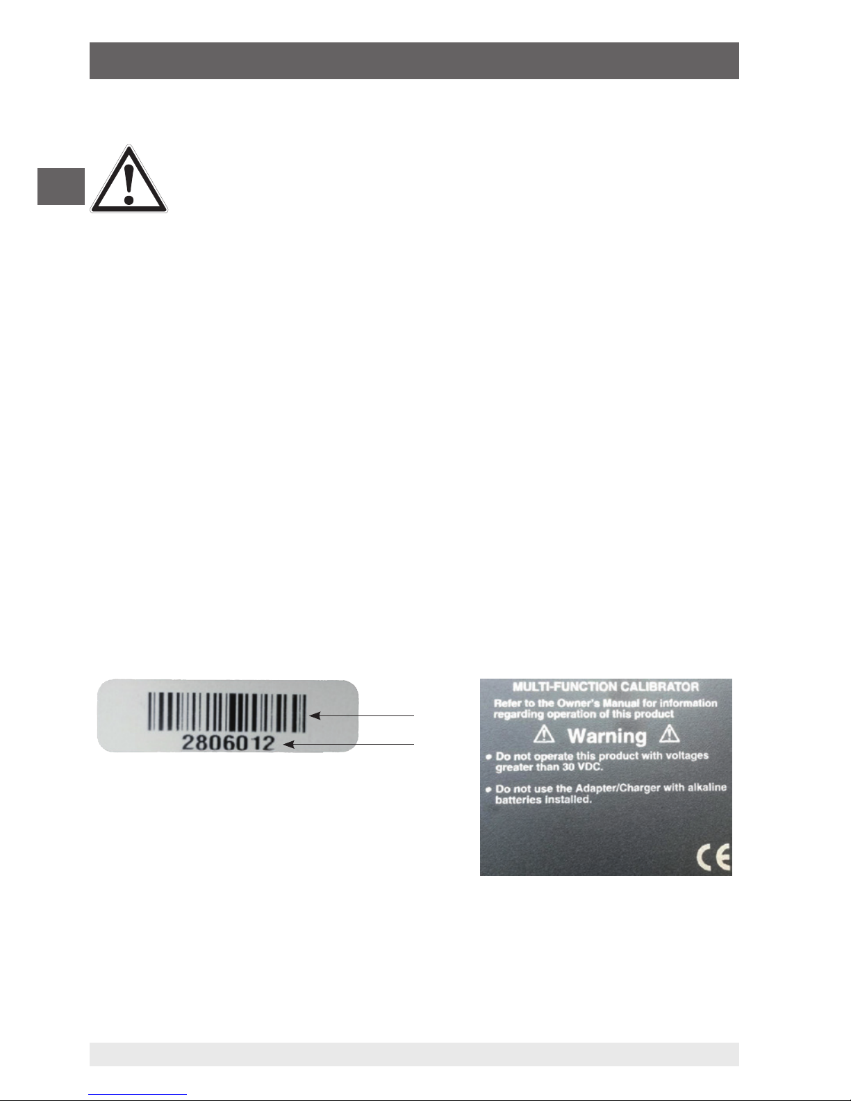
3.6 Labelling, safety marks
Product label
The product label is located on the side of the instrument beneath the protective rubber
boot.
Binary code
Serial no.
3. Safety
Page 11

11
WIKA operating instructions model CEP6100
14120028.01 04/2015 EN/DE
EN
Symbols
Before commissioning the instrument, ensure you read the operating
instructions!
Instruments bearing this mark comply with the relevant European directives.
This marking on the instruments indicates that they must not be disposed
of in domestic waste. The disposal is carried out by return to the manufacturer or by the corresponding municipal authorities (see EU directive
2002/96/EC).
3. Safety / 4. Design and function
4. Design and function
The model CEP6100 documenting multi-function calibrator is a battery-operated handheld instrument which can measure and output/simulate current, voltage, resistance,
RTD’s, TC’s, frequency and pulses.
In addition, external pressure sensors/pressure modules can be connected which enable
pressure to measure with this calibrator. The WIKA model CPT6600 pressure modules
and the Mensor model CPT6100/CPT6180 precision pressure sensors are compatible
here.
4.1 Front foil
The following figures show the location of the input and output terminals and also the
positions of the buttons on the calibrator.
Page 12

12
WIKA operating instructions model CEP6100
14120028.01 04/2015 EN/DE
EN
F1
HOME
7
F2 F3
89CE
E
N
T
E
R
4
1
MEASURE / SOURCE
3W
mA+
TC
V
mA
Loop
+
V
Hz
–
+
–
5
2
0
6
3
.
4W
mA–
MEASURE
–
CEP6100
Ω
1
2
3
4
6
8
9
7 5
4.1.1 Connections
4. Design and function
1
Connection for external pressure module
Connects the calibrator with a pressure module for pressure measurement.
2
Serial interface
Connects the calibrator with a PC for remote operation.
3
+
4
(Isolated) Current and voltage input as well as for output of DC 24 V voltage
supply
Terminals for the measurement of current, voltage and separate current loop supplies.
5
Thermocouple input/output
Terminal for the measurement or simulation of thermocouples. Suitable for polarised
miniature connectors for thermocouples.
6
+
7
Voltage, resistance thermometers (2-wire), frequency, pulse, input/output
Terminals for the simulation and measurement of voltage, frequency, pulse trains and
resistance thermometers (RTDs).
8
+
9
Current, resistance thermometers (3-wire, 4-wire), input/output
Terminals for the simulation and measurement of current and also for resistance
thermometer measurements with 3- and 4-wire connection.
Page 13

13
WIKA operating instructions model CEP6100
14120028.01 04/2015 EN/DE
EN
F1
HOME
7
F2 F3
89CE
E
N
T
E
R
4
1
MEASURE / SOURCE
3W
mA+
TC
V
mA
Loop
+
V
Hz
–
+
–
5
2
0
6
3
.
4W
mA–
MEASURE
–
CEP6100
Ω
1
2
3
4
6
8
7
5
4.1.2 Key function
4. Design and function
1
Display
2
Function keys, used to operate the menu bar at the bottom of the calibrator display
The [F1] key acts to select the options in the left-hand box, the [F2] key acts for the selection of
the functions in the middle box and the [F3] key for the selection of the functions in the righthand box.
3
Modification of individual digits of the output value; increase, decrease or ramp output
value
Use the left and right arrow buttons to select which digit in the output value should be changed.
With the up and down arrow keys, the output value can be increased, decreased or changed to
a ramp form.
4
Clear the input value
The last numerical value input will be deleted.
5
ENTER
Confirms the input of numerical values.
6
Numeric keys
Used for the input of numerical values.
7
HOME, returns to main menu
Reverts back to the start menu on the menu bar.
8
ON/OFF
Switches the calibrator on and off.
Page 14

14
WIKA operating instructions model CEP6100
14120028.01 04/2015 EN/DE
EN
4.2 Batteries
4.2.1 Selecting the batteries or rechargeable batteries
The model CEP6100 works with four alkaline batteries (AA) or with four NiMH
rechargeable batteries (AA).
4.2.2 Using the power supply unit
CAUTION!
Physical injuries and damage to property and the environment
If alkaline batteries are used in the model CEP6100 documenting multifunction calibrator, when the power supply unit is used at the same time,
overheating, severe damage and leakage can occur. Leakage of electrolyte from batteries presents a significant health risk.
▶
Only ever use the power supply unit without batteries or with NiMH
rechargeable batteries in the instrument.
▶
Only use undamaged and fault-free power supply units.
▶
Use WIKA accessories.
Using the power supply unit:
1. Remove alkaline batteries from the model CEP6100 or insert rechargeable batteries
in the calibrator’s compartments.
2. Connect the power supply unit to the calibrator.
3. Insert the power cord into the power connector.
Ensure that the correct power supply is present when doing this.
The NiMH rechargeable batteries in the instrument are recharged slowly.
Recharging takes between approx. 10 and 12 hours.
4. After use, disconnect the power cord from the mains and the calibrator.
4. Design and function
Page 15

15
WIKA operating instructions model CEP6100
14120028.01 04/2015 EN/DE
EN
5. Transport, packaging and storage
5. Transport, packaging and storage
5.1 Transport
Check the model CEP6100 documenting multi-function calibrator for any damage that
may have been caused by transport.
Obvious damage must be reported immediately.
CAUTION!
Damage through improper transport
With improper transport, a high level of damage to property can occur.
▶
When unloading packed goods upon delivery as well as during
internal transport, proceed carefully and observe the symbols on the
packaging.
▶
With internal transport, observe the instructions in chapter 5.2 “Packaging and storage”.
If the instrument is transported from a cold into a warm environment, the formation of
condensation may result in instrument malfunction. Before putting it back into operation,
wait for the instrument temperature and the room temperature to equalise.
5.2 Packaging and storage
Do not remove packaging until just before use.
Keep the packaging as it will provide optimum protection during transport (e.g. change in
place of use, sending for repair).
Permissible conditions at the place of storage:
■
Storage temperature: -20 ... +60 °C
■
Humidity: 0 ... 90 % relative humidity (non-condensing)
Avoid exposure to the following factors:
■
Direct sunlight or proximity to hot objects
■
Mechanical vibration, mechanical shock (putting it down hard)
■
Soot, vapour, dust and corrosive gases
■
Hazardous environments, flammable atmospheres
Page 16

16
WIKA operating instructions model CEP6100
14120028.01 04/2015 EN/DE
EN
5. Transport, packaging and storage / 6. Commissioning, ...
Store the model CEP6100 documenting multi-function calibrator in its original packaging
in a location that fulfils the conditions listed above. If the original packaging is not
available, pack and store the instrument as described below:
1. Wrap the instrument in an antistatic plastic film.
2. Place the instrument, along with shock-absorbent material, in the packaging.
3. If stored for a prolonged period of time (more than 30 days), place a bag containing a
desiccant inside the packaging.
6. Commissioning, operation
ATTENTION!
Damage through electric shock
Higher voltages than the rated voltage can cause damage to the model
CEP6100 documenting multi-function calibrator. With any damage to the
case or the test cables, an electric shock can result from any contact.
▶
Apply the correct rated voltage, see chapter 10 “Specifications”.
▶
Do not use the calibrator if it is damaged. Prior to use check the case of
the calibrator. Pay attention to missing plastic components and cracks,
in particular to the insulation around the connections.
▶
Do not use the calibrator in case of malfunction. The instrument
protection might be compromised. In case of doubt, have the calibrator
checked.
▶
The battery compartment must be closed and sealed.
▶
Change the batteries as soon as the battery symbol is displayed.
▶
Always use the correct connector sockets, functions and measuring
ranges for the measurement or simulation.
▶
Only open the battery compartment once all cable connections have
been disconnected from the calibrator.
▶
Check the test cables for damaged insulation or bare metal components. Test the continuity of the test cables. Replace any damaged test
cable before using the calibrator.
▶
Do not touch the metal parts at the test cables.
As soon as the model CEP6100 documenting multi-function calibrator is turned on, by
pressing the ON/OFF key, it will go through a short self-test routine. During this routine,
the display shows the current firmware version and the auto-shutdown status.
The calibrator requires a maximum of 5 minutes warm-up to reach its specified accuracy.
Large changes in ambient temperature may make a longer warm-up period necessary.
Page 17

17
WIKA operating instructions model CEP6100
14120028.01 04/2015 EN/DE
EN
6. Commissioning, operation
6.1 Main display
The display of the model CEP6100 documenting multi-function calibrator is subdivided
into 3 main sections: the upper display, the lower display and the menu bar.
■
The upper display is used for the measurement of direct current voltages, direct
current (with or without loop voltage) and for pressure measurement.
■
The lower display can be used both for measurement and for simulation.
■
The menu bar (at the bottom of the display) serves for configuration of the upper and
lower display (according to the desired function).
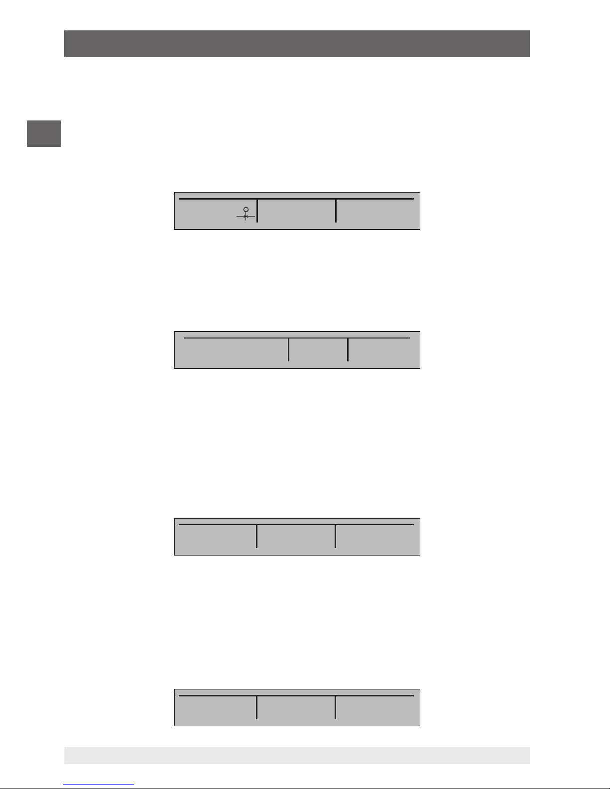
The following figure shows the location of the various display fields, which are described
in the table.
Numeric display
Displays the numeric value of the measured or simulated signal.
A measurement “OL” or “-OL” signals a value outside of the measuring range.
Display of the span
Only for the display “mA” and “mA LOOP”.
Displays the current measured value with respect to 4 mA = 0 % and 20 mA = 100 %.
Units
Displays the corresponding unit for measurement or output/simulation.
For “RTD” (resistance thermometer) and “TC” (thermocouple), °C or °F are offered; for
“FREQ” (frequency) and “PULSE” (pulse), CPM, Hz or kHz.
mA IN
0.000 mA
-25.00%
RTD IN 4W P10-385
MENU
-OL °C
LIGHT
2
3
4
7
6
5
1
1
2
3
Page 18

18
WIKA operating instructions model CEP6100
14120028.01 04/2015 EN/DE
EN
6. Commissioning, operation
Sensor type
For measurements and simulation of various resistance thermometers (RTDs) and
thermocouples (TCs).
All possible sensor types are stated in the specifications (see chapter 10 “Specifications”). The options also show the amplitude of the pulse or frequency simulation and
the pressure unit.
Additional settings
Only available for the option “TC measurement” (thermocouple) and
“RTD measurement” (resistance thermometer).
With the option “TC”, this setting switches the cold junction compensation (CJC) on or
off.
With RTD measurements, this setting defines the number of wires for the
measurement (2W = 2-wire measurement, 3W = 3-wire measurement,
4W = 4-wire measurement).
Input/output display
Switches the lower display between input mode (measuring) and output mode
(output/simulation).
Primary parameters
Defines which parameter will be measured or outputted/simulated.
The available options for the upper display are: “VOLTS IN” (input voltage),
“PRESSURE” (pressure), “mA IN” (input current in mA) and “mA LOOP” (mA with
DC 24 V voltage supply).
The available options for the lower display are: “VOLTS” (voltage),
“TC” (thermocouple), “RTD” (resistance thermometer), “FREQ” (frequency),
“PULSE” (pulse), “PRESSURE” (pressure) and “mA” (current) or
“mA 2W SIM” (current simulation).
6.2 Menu bar
The display parameters are managed via the menu bar, which is found along the bottom
of the LC display. The function keys [F1], [F2] and [F3] enable navigation through all levels
and options of the menu bar. The upper menu level is the start menu.
One can return to this at any time with the [HOME] key. There are three variants of the
start menu: the input start menu, the output start menu and the pulse start menu.
6.2.1 “Measuring” menu function
In the start menu for the function “Measuring”, only the options “MENU” and “LIGHT” are
active. The option “MENU” calls the next menu level to the menu bar, i.e. to call the main
menu. Press the corresponding function key, [F1], to call the main menu.
4
5
6
7
Page 19

19
WIKA operating instructions model CEP6100
14120028.01 04/2015 EN/DE
EN
6. Commissioning, operation
The option “LIGHT” switches on the backlight for the LC display. Press the corresponding
function key [F2] to switch on the backlighting.
6.2.2 “Output” menu function
In the start menu for the function “Output” there are three active options “MENU”, “LIGHT”
and “STEP” or “RAMP”.
The first two options work just like in the start menu. The third option can be selected
via the automatic output function menu option, and acts to switch on or off the selected
automatic function. For further information, see chapter 6.5.2 “Using the automatic output
functions”. The automatic output functions are stopped as soon as the menu is exited or
the [HOME] key is pressed.
6.2.3 “Pulse output” menu function
The pulse start menu also has three active options, “MENU”, “TRIG” and “COUNTS”.
The options “TRIG” and “COUNTS” are used for pulse simulation. The function of these
options is explained in chapter 6.5.7 “Pulse output”.
6.2.4 “UPPER”, “LOWER” and “MORE” menu function
The next level of the menu bar is the main menu itself. Which levels are available under
the main menu depends on the selected operating mode of the calibrator. The options are
“UPPER”, “LOWER” and “MORE”.
With “UPPER”, the selection menu for the parameters of the upper display will be called.
With “LOWER”, the selection menu for the parameters of the lower display will be called.
“MORE” switches to the next menu level.
MENU LIGHT
MENU LIGHT STEP
MENU TRIG
COUNTS
UPPER LOWER MORE
Page 20

20
WIKA operating instructions model CEP6100
14120028.01 04/2015 EN/DE
EN
6.2.5 “Documentation” menu function
This “Documentation” menu level is used for saving calibrations. The options are
“DOCUMENT”, “NEXT” and “DONE”. By selecting “DOCUMENT”, one enters the
documentation menu.
“NEXT” switches to the next menu function and “DONE” returns to the start menu. For
further information, see chapter 7 “Document mode”.
6.2.6 “Automatic output function” menu function
The “Automatic output function” is a menu function in the “Output” mode and is called by
pressing “MORE”. The options are “AUTO FUNC”, “NEXT” and “DONE”.
With “AUTO FUNC” the parameters of the automatic output function can be set. “NEXT”
switches to the next menu function and “DONE” returns to the start menu. For further
information, see chapter 6.5.2 “Using the automatic output functions”.
6.2.7 “Frequency or pulse output” menu function
When the lower display is used for frequency or pulse outputs, in addition, the sub-menu
for frequency is displayed after the main menu. The options are “FREQ LEVEL”, “NEXT”
and “DONE”.
The option “FREQ LEVEL” enables the setting of the amplitude of the oscillation. “NEXT”
switches to the next menu function and “DONE” returns to the start menu.
6.2.8 “Contrast” menu function
The next menu level is the contrast menu. The options are “CONTRAST”, “NEXT” and
“DONE”.
The option “CONTRAST” acts to set the contrast. “NEXT” switches to the next menu
function and “DONE” returns to the start menu. The contrast can be set with the arrow
keys [F1, F2], which are displayed after selecting the option “CONTRAST”.
In certain cases, large changes in contrast can make the display difficult to read under
normal conditions. If the display is too bright or too dark for the values to be read, the
following steps should be taken in order to reset the contrast setting to the default.
DONENEXTDOCUMENT
AUTO FUNC
NEXT DONE
FREQ LEVEL
NEXT DONE
6. Commissioning, operation
Page 21

21
WIKA operating instructions model CEP6100
14120028.01 04/2015 EN/DE
EN
1. Turn the instrument on while holding the [HOME] key down.
2. Hold this button down for 10 seconds in order to reset the factory settings for the
contrast. If the display is so light that it is not possible to see whether the instrument is
switched on or off, use the button for the backlighting as an indication of this.
6.2.9 “Automatic switch-off” menu function
The main menu for the automatic switch-off contains the options “AUTO OFF”, “NEXT”
and “DONE”.
The option “AUTO OFF” acts to switch on and off the automatic switch-off function and
specifies how long the instrument remains in standby before it switches off. “NEXT”
switches to the next menu function and “DONE” returns to the start menu.
6.2.10 “Time” menu function
“Time” is the next menu level. The options are “CLOCK”, “NEXT” and “DONE”. With
“CLOCK”, the date and time can be set.
“NEXT” switches to the next menu function and “DONE” returns to the start menu.
6.2.11 “Probe-specific coefficients” menu function
If the calibrator is working in the “RTD CUSTOM” mode, following the main menu,
the RTD menu for the user-defined configuration is displayed. The options are “SET
CUSTOM”, “NEXT” and “DONE”.
The option “SET CUSTOM” enables the input of the coefficients of a user-defined “PRT”
(platinum resistance thermometer) into the calibrator. “NEXT” switches to the next menu
function and “DONE” returns to the start menu.
CONTRAST
NEXT DONE
AUTO OFF NEXT DONE
CLOCK NEXT DONE
SET CUSTOM
NEXT DONE
6. Commissioning, operation
Page 22
22
WIKA operating instructions model CEP6100
14120028.01 04/2015 EN/DE
EN
6.2.12 “ZERO” menu function
Resetting the pressure to the zero value is the final option on selecting “MORE” in the
main menu and is only shown if an external pressure sensor is connected. The options
are “ZERO”, “NEXT” and “DONE”.
The option “ZERO” acts to reset the pressure to zero. “NEXT” switches to the next menu
function and “DONE” returns to the start menu. For further information on resetting to 0,
see chapter 6.4.4 “Measuring pressure”.
6.2.13 “Terminal emulation” menu function
The menu point “Terminal emulation” is the last under the displayed “MORE” menu.
“TERMINAL”, “NEXT” and “DONE”. With “TERMINAL”, the Terminal Emulation menu is
selected. “NEXT” and “DONE” return to the start menu.
6.2.14 “Parameter selection” menu function
The menu for parameter selection is called via the main menu using “UPPER” or
“LOWER”. The options are “SELECT”, “NEXT” and “DONE”. When selected, one parameter flashes in the display.
Using the option “SELECT”, the parameter can be altered. With the option “NEXT”, one
can switch to another variable. “DONE” switches back to the start menu and accepts the
selection.
6.3 Cursor control/set-point control
The output value can be changed using the four arrow keys on the keypad. If an arrow key
is pressed, a cursor appears under the last digit of the output value. Use the left and right
arrow buttons to select which digit in the output value should be changed. With the up
and down arrow keys, the output value can be increased or decreased. The menu bar will
change to the set-point menu, as soon as one of the four arrow keys is pressed.
ZERO NEXT DONE
NEXT DONE
TERMINAL
SELECT NEXT DONE
0% 25% 100%
6. Commissioning, operation
Page 23

23
WIKA operating instructions model CEP6100
14120028.01 04/2015 EN/DE
EN
The three function keys are assigned the values “0 %”, “25 %” and “100 %”. The value
for 0 and 100 % can be saved through the input of a value, when the corresponding
function key is held down at the same time. The key for “25 %” then switches to the value
corresponding to 25 %.
6.4 Using the measuring modes (lower display)
6.4.1 Measuring voltage and frequency
To measure voltage or frequency, follow the steps below:
1. In the main menu, switch to the lower display “LOWER” and select “V” or “FREQ”.
2. The input/output setting must be set to “IN”.
3. Connect the test cables (see following figure).
6.4.2 Measuring current (mA)
To measure current in mA, follow the steps below:
1. In the main menu, switch to the lower display “LOWER” and select “mA”.
2. The input/output setting must be set to “IN”.
3. Connect the test cables (see following figure).
Measuring voltage and frequency with the input and output terminals
MEASURE / SOURCE
3W
mA+
TC
V
mA
Loop
+
V
Hz
–
+
4W
mA–
MEASURE
–
–
+
Ω
VOLTS IN
-0.000 V
VOLTS IN
MENU
5.000 V
LIGHT
Measuring current in mA at the input and output terminals
MEASURE / SOURCE
3W
mA+
TC
V
mA
Loop
+
V
Hz
–
+
4W
mA–
MEASURE
–
–
+
Ω
mA IN
0.000 mA
-25.00%
mA IN
MENU
5.000 mA
LIGHT
6. Commissioning, operation
Page 24

24
WIKA operating instructions model CEP6100
14120028.01 04/2015 EN/DE
EN
6.4.3 Measuring temperature
6.4.3.1 Using thermocouples
The calibrator supports the following types of
thermocouples: B, C, E, J, K, L, N, R, S, T, U, BP and
XK. The typical characteristics of all of these types
are described in chapter 10 “Specifications”. The
calibrator also has a “CJC” (cold junction compensation) function. In normal operation, the function
will be activated, and it will measure the effective
temperature of the thermocouple. If the option
“CJC” is deactivated, the calibrator measures the
difference between the thermocouple at the connection point and the input terminal of the
thermocouple.
The CJC option should only be deactivated when the calibration is being
made with an external ice bath.
To measure temperature with the thermocouple, follow the steps below:
1. Connect the wires of the thermocouple to the input/output of the calibrator using the
thermocouple mini-connector (see following figure).
The connecting cable for the thermocouple must match the type of the
thermocouple being calibrated.
2. In the main menu, switch to the lower display “LOWER” and select “TC”.
3. The input/output setting must be set to “IN”.
4. Select the corresponding thermocouple type in the menu.
5. Select temperature unit.
In the interests of optimum accuracy, wait 2 to 5 minutes so that the
temperature between the mini-connector and the calibrator stabilises.
After this, carry out the measurement.
The calibrator can measure the voltage of the thermocouple in mV, so that the temperature can be determined with the aid of a table if the corresponding thermocouple type is
not supported by the calibrator. For the case described above, proceed and select “mV”
as the type.
mA IN
0.000 mA
-25.00%
TC IN CJC OFF B
MENU
OL °C
LIGHT
6. Commissioning, operation
Page 25

25
WIKA operating instructions model CEP6100
14120028.01 04/2015 EN/DE
EN
6.4.3.2 Using resistance thermometers (RTDs)
The supported resistance thermometers are detailed in the specifications in chapter
10 “Specifications”. The specific characteristic of RTDs is their temperature-dependent
resistance (R0). The calibrator can work with input signals with 2-, 3- or 4-wires, where
input measurements with 4-wire connection are the most accurate.
To measure temperature with resistance thermometers, follow the steps below:
1. In the main menu, switch to the lower display “LOWER” and select “RTD”.
2. The input/output setting must be set to “IN”.
3. Select 2-, 3- or 4-wire connection “2W, 3W, 4W”.
4. Select the corresponding RTD type in the menu.
5. Select temperature unit.
6. Connect the RTD wires (see following figure).
MEASURE / SOURCE
3W
mA+
TC
V
mA
Loop
+
V
Hz
–
+
4W
mA–
MEASURE
–
+
–
Ω
Measuring temperature at the thermocouple terminal
Thermocouple plug
MEASURE / SOURCE
3W
mA+
TC
V
mA
Loop
+
V
Hz
–
+
4W
mA–
MEASURE
–
–
+
–
+
–
+
–
+
–
+
–
+
3W
4W
RTD
RT
D
RT
D
2W
Ω
mA IN
0.000 mA
-25.00%
RTD IN 4W P10-385
MENU
25.0 °C
LIGHT
Measuring temperature with RTD probe connected
6. Commissioning, operation
Page 26

26
WIKA operating instructions model CEP6100
14120028.01 04/2015 EN/DE
EN
The resistance can also be measured with this function. For this, follow the steps as
described above, and as RTD type, select “OHMS”. With this option and a measurement
table, an RTD probe that is not programmed into the calibrator can also be used for
measurement.
6.4.4 Measuring pressure
CAUTION!
Pressurisation
Damage within the pressure system due to open valves.
1. Close the valve.
2. Release the pressure slowly.
3. Connect the pressure module to the pressure line.
ATTENTION!
Damage to the threaded connections
The pressure module can be damaged by over-tightening the threaded
connection.
▶
Use suitable tools.
▶
Tighten the pressure connection with a maximum of 13.6 Nm (torque
spanner).
▶
Never exceed the permissible maximum pressure.
▶
Only use pressure modules with compatible media. See specification of
the pressure module.
To measure pressure with external pressure modules, follow the steps below:
1. Connect the pressure module to the calibrator using the pressure module adapter (see
following figure).
For the connection of the pressure module to the calibrator, a WIKA
pressure module adapter must be used.
2. From the main menu, switch to the upper or lower display as required. The calibrator
measures pressure in the upper as well as the lower display. In this way, pressure can
be measured on two different units at the same time.
3. As the primary parameter, select “PRESSURE”.
4. Select the desired unit of measure.
6. Commissioning, operation
Page 27

27
WIKA operating instructions model CEP6100
14120028.01 04/2015 EN/DE
EN
With high-pressure modules, technical units of measure that are only
used for low pressure ranges, such as inH
2
O, cmH2O, etc., are not valid
selections. If one of these units is selected with a high-pressure module
connected, “----” is shown on the display.
5. Set the pressure module to zero (ZERO). The function to reset the calibrator is found
under the “ZERO” menu function.
6.4.4.1 Zeroing of absolute pressure modules
To reset the calibrator to zero, set it so that it measures a known pressure, for example the
barometric pressure.
To zero the calibrator, follow the steps below:
1. Call up the menu function “ZERO”.
2. Select “ZERO”. “SET REFERENCE ABOVE” will
be displayed.
3. Enter the reference pressure via the keypad.
The calibrator saves the barometric reference value
in permanent memory. The reference value will
always be saved for an absolute pressure module. If
a new absolute pressure module is connected, this
procedure must be repeated.
F1
HOME
7
F2 F3
89CE
E
N
T
E
R
4
1
MEASURE / SOURCE
3W
mA+
TC
V
mA
Loop
+
V
Hz
–
+
–
5
2
0
6
3
.
4W
mA–
MEASURE
–
CEP6100
Ω
Connection for pressure measurement
Valve
Pressure
module
Pressure module
adapter
PRESSURE
-------
psi
PRESSURE mbar
MENU
-------
LIGHT
6. Commissioning, operation
Page 28

28
WIKA operating instructions model CEP6100
14120028.01 04/2015 EN/DE
EN
6.5 Using the output modes (lower display)
The calibrator can generate signals for testing and calibrating process instruments. It can
simulate voltage, current, resistance, frequency, pulses and the electrical output signal of
a resistance thermometer or a thermocouple.
6.5.1 Setting the output parameters 0 % and 100 %
To enter the 0 % and 100 % points, follow the steps below:
1. Select the lower display “LOWER” from the main menu and then select the required
function.
2. Select the output “OUT” at the input/output setting and enter the desired value.
(example: “VOLTS OUT”).
3. On the keypad, enter (for example) 5 V and press the enter key.
4. Press one of the arrow keys in order to select the set point setting from the menu.
5. Hold down the function key for “0 %” [F1]. The value 0 % will flash for a short time and
the set point (e.g. 5 V) will be saved.
6. Repeat these steps with (for example) 20 V and hold down the function key for “100 %”
[F3].
7. With the function key for “25 %”, it is now possible to move between 5 V and 20 V in
steps of 25 %.
6.5.1.1 Increasing the output current in steps
To use the 25 % function with an output signal in the mA range, follow the steps
below:
1. Select the option “mA” for the lower display from the main menu.
2. With the key for “25 %”, it is possible to move between 4 mA and 20 mA in intervals of
25 %.
6.5.2 Using the automatic output functions
The step function and automatic ramp function are available as automatic output
functions. The selected function can be switched on and off via the start menu (“STEP” or
“RAMP”). The automatic output parameters can be set in the menu via “Automatic output
function”.
The parameters include:
■
Which automatic output function is available (step function or ramp function).
■
The time for the automatic output function defines the time between the individual
steps or, in the ramp function, the time between the first and second limit value in the
ramp.
■
The limit values for the ramp mode and step function are set to 0 % and 100 %.
6. Commissioning, operation
Page 29

29
WIKA operating instructions model CEP6100
14120028.01 04/2015 EN/DE
EN
For further information, see chapter 6.5.1 “Setting the output parameters 0 % and
100 %”. The step increase is made in 25 % steps from 0 % to 100 %.
6.5.3 Current output
To output a current, follow the steps below:
1. In the main menu, switch to the lower display “LOWER” and select “mA”.
2. The input/output setting must be set to “OUT”.
3. Connect the test cables to the terminals for current output (see following figure).
4. Enter the desired current value via the keypad.
6.5.3.1 HART
®
resistor selection
The CEP6100 can be configured so that the 250 Ω resistor for HART
®
compatible
instruments can be activated within the CEP6100. If the internal 250 Ω resistor within the
CEP6100 is used, a serial resistance for the calibration of HART
®
modules does not have
to be activated.
When using the internal 250 Ω resistor, the maximum load resistance is
reduced from 1,000 Ω to 750 Ω, at a current of 20 mA.
6.5.3.2 HART
®
resistor, activation/deactivation procedure
1. Remove the battery cover and loosen both of the screws on the upper part of the case.
2. Remove both of the screws on the lower part of the case.
3. Carefully remove the upper half of the case from the lower half.
The following picture indicates the position of the HART
®
jumpers.
mA LOOP
0.000 mA
-25.00 %
mA OUT
MENU
5.000 mA
LIGHT
–
+
UUT
MEASURE / SOURCE
3W
mA+
TC
V
mA
Loop
+
V
Hz
–
+
4W
mA–
MEASURE
–
Ω
Connection for use as a mA source
6. Commissioning, operation
Page 30

30
WIKA operating instructions model CEP6100
14120028.01 04/2015 EN/DE
EN
6.5.4 Simulating a transmitter
To use the calibrator to simulate a transmitter in a current loop, follow the steps
below:
1. In the main menu, switch to the lower display “LOWER” and select “mA 2W SIM”.
2. Enter the desired current with the keypad.
3. Connect the test cables to the terminals for current input (see following figure).
3. Connect the external DC 24 V voltage supply (see following figure).
OFF
OFF
ON
ON
Position of the HART® jumpers
HART® resistor
Circuit board
MEASURE / SOURCE
3W
mA+
TC
V
mA
Loop
+
V
Hz
–
+
4W
mA–
MEASURE
–
–
–
+
+
UUT
Ω
mA IN
0.000 mA
-25.00%
mA 2W SIM
MENU
4.000 mA
LIGHT
Connection for the transmitter simulation
30 V max.
Voltage
supply
6. Commissioning, operation
Page 31

31
WIKA operating instructions model CEP6100
14120028.01 04/2015 EN/DE
EN
6.5.5 Voltage output
To output a voltage, follow the steps below:
1. In the main menu, switch to the lower display “LOWER” and select “VOLTS”.
2. The input/output setting must be set to “OUT”.
3. Connect the test cables to the terminals for voltage output (see following figure).
4. Enter the desired voltage value via the keypad.
6.5.6 Frequency output
To output a frequency, follow the steps below:
1. In the main menu, switch to the lower display
“LOWER” and select “FREQ”.
2. The input/output setting must be set to “OUT”.
3. Set the corresponding frequency unit.
4. Connect the test cables to the terminals for
frequency output (see figure “Connections for
voltage, frequency and pulse outputs”).
5. Enter the desired frequency value via the keypad.
6. To change the amplitude, select the “FREQ
LEVEL” option in the “Frequency or pulse output” menu function.
7. Enter the desired amplitude value via the keypad.
6.5.7 Pulse output
The calibrator can generate a pulse train with an
adjustable number of pulses at a desired frequency.
As an example, if the frequency is set to 60 Hz and
the number of pulses set to 60, the calibrator will
generate 60 pulses in the space in 1 second.
For operation as a pulse generator, the same
connections are used as for frequency “Output”.
–
+
UUT
MEASURE / SOURCE
3W
mA+
TC
V
mA
Loop
+
V
Hz
–
+
4W
mA–
MEASURE
–
Ω
mA LOOP
0.000 mA
-25.00%
mA OUT
MENU
6.000 V
LIGHT
Connections for voltage, frequency and pulse outputs
mA IN
0.000 mA
-25.00%
FREQ OUT
5.0 Vpp
MENU
4.0 kHz
LIGHT
mA LOOP
0.000 mA
-25.00%
PULSE
5.0 Vpp
MENU
5.0 kHz
TRIG COUNTS
6. Commissioning, operation
Page 32

32
WIKA operating instructions model CEP6100
14120028.01 04/2015 EN/DE
EN
6. Commissioning, operation
To output a pulse, follow the steps below:
1. In the main menu, switch to the lower display “LOWER” and select “PULSE”.
2. Set the corresponding pulse unit.
3. Connect the test cables to the terminals for pulse output (see figure “Connections for
voltage, frequency and pulse outputs”).
4. With the function “COUNTS” in the start menu, the number of pulses is set. The signal
is started and stopped using the “TRIG” key.
5. To change the amplitude, select the “FREQ LEVEL” option in the “Frequency or pulse
output” menu function.
6.5.8 Simulating thermocouples
To simulate a thermocouple, follow the steps below:
1. Connect the wires of the thermocouple to the input/output of the calibrator using the
thermocouple mini-connector (see following figure).
2. In the main menu, switch to the lower display “LOWER” and select “TC”.
3. The input/output setting must be set to “OUT”.
4. Select the corresponding thermocouple type in the menu.
5. Select temperature unit.
6. Enter the temperature value or voltage value, respectively, via the keypad.
Used thermocouple wire must match the thermocouple type being
calibrated.
6.5.9 Simulating resistance or resistance thermometers
To simulate a resistance/resistance thermometer, follow the steps below:
1. Connect the wires of the RTD type to the input/output of the calibrator (see following
figure).
mA IN
0.000 mA
-25.00%
TC OUT CJC OFF
E
MENU
100.0 °C
LIGHT
MEASURE / SOURCE
3W
mA+
TC
V
mA
Loop
+
V
Hz
–
+
4W
mA–
MEASURE
–
–
+
+
–
Ω
Simulating the temperature at the thermocouple terminal
Thermocouple plug
Page 33

33
WIKA operating instructions model CEP6100
14120028.01 04/2015 EN/DE
EN
6. Commissioning, operation
2. In the main menu, switch to the lower display “LOWER” and select “RTD”.
3. The input/output setting must be set to “OUT”.
4. Select the corresponding RTD type in the menu.
5. Select temperature unit.
6. Enter the temperature value or resistance value, respectively, via the keypad.
The calibrator simulates an RTD probe with 2-wires. To connect a probe
with 3- or 4-wires, use the stackable test cables (see following figure).
mA LOOP
0.000 mA
-25.00%
RTD OUT P500-385
MENU
10.0 °C
LIGHT
MEASURE / SOURCE
3W
mA+
TC
V
mA
Loop
+
V
Hz
–
+
4W
mA–
MEASURE
–
Ω
Simulating resistance or resistance thermometers
3W
4W
1
1
2
2
3
3
4
4
MEASURE / SOURCE
3W
mA+
TC
V
mA
Loop
+
V
Hz
–
+
4W
mA–
MEASURE
–
MEASURE / SOURCE
3W
mA+
TC
V
mA
Loop
+
V
Hz
–
+
4W
mA–
MEASURE
–
Ω Ω
3- or 4-wire connection for RTDs
Use stackable test
cables for common
connections
Page 34

34
WIKA operating instructions model CEP6100
14120028.01 04/2015 EN/DE
EN
6. Commissioning, operation
6.5.9.1 Customer-specific resistance thermometer (RTD)
To achieve the highest possible accuracy, it is possible to load probe-specific resistance
thermometer coefficients into the calibrator.
To enter probe-specific coefficients, follow the steps below:
1. In the main menu, switch to the lower display “LOWER” and select “RTD”.
2. Select RTD type “CUSTOM”.
3. Select “Probe-specific coefficients” menu function.
4. Enter the values requested by the calibrator using the keypad.
▶
Minimum temperature
▶
Maximum temperature
▶
R
0
▶
Temperature coefficients
The custom function uses the Callendar–Van Dusen equation for output and measure-
ment of custom resistance thermometers. The coefficient C is used only for temperatures
below 0 °C. For the range above 0 °C, only the coefficients A and B are required, so
coefficient C is then set to 0. R
0
is the resistance of the probe at 0 °C.
Coefficients for Pt385, Pt3926 and Pt3616
RTD Range R0 Coefficient A Coefficient B Coefficient C
Pt385 -260 ... 0 °C 100 3.9083 x 10
-3
-5.775 x 10
-7
-4.183 x 10
-12
Pt385 0 ... 630 °C 100 3.9083 x 10
-3
-5.775 x 10
-7
-
Pt3926 Under 0 °C 100 3.9848 x 10
-3
-5.87 x 10
-7
-4 x 10
-12
Pt3926 Above 0 °C 100 3.9848 x 10
-3
-5.87 x 10
-7
-
Pt3916 Under 0 °C 100 3.9692 x 10
-3
-5.8495 x 10
-7
-4.2325 x 10
-12
Pt3916 Above 0 °C 100 3.9692 x 10
-3
-5.8495 x 10
-7
-
6.6 Using the isolated measuring modes (upper display)
6.6.1 Measuring voltage (V) or current (mA)
To measure voltage or current on the isolated input channel, follow the steps
below:
1. In the main menu, switch to the upper display “UPPER” and select “V” or “mA”.
2. Connect the test cables to the calibrator’s isolated inputs (see following figure).
Page 35

35
WIKA operating instructions model CEP6100
14120028.01 04/2015 EN/DE
EN
6. Commissioning, operation
6.6.2 Measuring current with DC 24 V voltage supply
To test a 2-wire transmitter, which has an external power supply that is not connected,
use the function for separate voltage supply. This function activates a DC 24 V voltage
supply in series with the measuring current loop.
To measure current with a DC 24 V voltage supply on the isolated input channel,
follow the steps below:
1. In the main menu, switch to the upper display “UPPER” and select “mA LOOP”.
2. Connect the test cables to the calibrator’s isolated inputs (see following figure).
6.7 Using the upper and lower displays for test and calibration
6.7.1 Calibrating a display instrument
To calibrate recording and display instruments using the output functions, follow
the steps below:
1. In the main menu, switch to the lower display “LOWER” and select the corresponding
parameter.
–
MEASURE / SOURCE
3W
mA+
TC
V
mA
Loop
+
V
Hz
–
+
4W
mA–
MEASURE
–
+
Isolated input
MEASURE / SOURCE
3W
mA+
TC
V
mA
Loop
+
V
Hz
–
+
4W
mA–
MEASURE
–
–
+
Ω
mA LOOP
0.000 mA
-25.00%
mA IN
MENU
-0.001 mA
LIGHT
Isolated input
Page 36

36
WIKA operating instructions model CEP6100
14120028.01 04/2015 EN/DE
EN
6. Commissioning, operation
2. The input/output setting must be set to “OUT”.
3. Connect the test cables to the calibrator (see following figure).
6.7.2 Calibrating an I/P instrument
To calibrate pressure-controlling instruments, follow the steps below:
1. In the main menu, switch to the upper display “UPPER” and select “PRESSURE”.
2. In the main menu, switch to the lower display “LOWER” and select “mA”.
3. The input/output setting must be set to “OUT”.
4. Connect the calibrator to the sensor using the mA output (see following figure).
5. Enter the current value via the keypad.
MEASURE / SOURCE
3W
mA+
TC
V
mA
Loop
+
V
Hz
–
+
4W
mA–
MEASURE
–
Ω
Connection of a display instrument
Maximum current: 1 mA
F1
HOME
7
F2 F3
89CE
E
N
T
E
R
4
1
MEASURE / SOURCE
3W
mA+
TC
V
mA
Loop
+
V
Hz
–
+
–
5
2
0
6
3
.
4W
mA–
MEASURE
–
CEP6100
Ω
–
+
Calibrating an I/P instrument
Pressure module
and pressure
module adapter
Page 37

37
WIKA operating instructions model CEP6100
14120028.01 04/2015 EN/DE
EN
6. Commissioning, operation
The calibrator simulates the transmitter current and measures the output
pressure with an external pressure module.
6.7.3 Calibrating a transmitter
To calibrate a transmitter, both displays (“UPPER” and “LOWER”) are used - the upper
display for measurement and the lower for output/simulation. In this example, a thermocouple transmitter is calibrated.
To calibrate TC temperature transmitters, follow the steps below:
1. In the main menu, switch to the upper display “UPPER” and select “mA LOOP”.
2. In the main menu, switch to the lower display “LOWER” and select “TC”.
3. The input/output setting must be set to “OUT”.
4. Set the end values 0 % and 100 % with the keypad and set the [0 %] and [100 %] keys
(also see chapter 6.5.1 “Setting the output parameters 0 % and 100 %”).
5. Connect the calibrator with the TC output to the TC input of the transmitter. In addition,
connect the calibrator, using its mA input, to the mA output of the transmitter (see
following figure).
6. Output a temperature value using the keypad or test 0-25-50-75-100 % using the 25 %
step function (25 % key).
To calibrate a different type transmitter, follow the steps above with the
exception of the selection of the lower display. Set the thermocouple with
the correct parameters for the transmitter.
MEASURE / SOURCE
3W
mA+
TC
V
mA
Loop
+
V
Hz
–
+
4W
mA–
MEASURE
–
Ω
Calibrating a TC temperature transmitter
Page 38

38
WIKA operating instructions model CEP6100
14120028.01 04/2015 EN/DE
EN
6. Commissioning, operation / 7. Document mode
6.7.4 Calibrating a pressure transmitter
To calibrate pressure transmitters, follow the steps below:
1. In the main menu, switch to the upper display “UPPER” and select “mA LOOP”.
2. In the main menu, switch to the lower display “LOWER” and select “PRESSURE”.
3. Connect the calibrator with the mA input to the mA output of the pressure transmitter.
In addition, connect the external pressure module with the pressure connection of the
pressure transmitter (see following figure).
4. Zero the pressure module (see chapter 6.2.10 ““ZERO” menu function”).
5. Test the pressure transmitter at (for example) 0 % and 100 % of the measuring range.
Pressure module
and pressure
module adapter
–
+
F1
HOME
7
F2 F3
89CE
E
N
T
E
R
4
1
MEASURE / SOURCE
3W
mA+
TC
V
mA
Loop
+
V
Hz
–
+
–
5
2
0
6
3
.
4W
mA–
MEASURE
–
CEP6100
Ω
Calibrating a pressure transmitter
7. Document mode
7.1 Introduction
Document mode enables an instrumentation technician to create up to 50 calibrations
on site and to import predefined calibrations from a PC database. Each calibration can
consist of between 1 and 21 freely selectable test points. For each test item, an initial
calibration (AS FOUND [AF]) and a final calibration (AS LEFT [AL]) can be carried out
and is saved.
Page 39

39
WIKA operating instructions model CEP6100
14120028.01 04/2015 EN/DE
EN
TEST REVIEW EXIT
AS FOUND AS LEFT EXIT
UPPER LOWER DONE
SELECT NEXT DONE
NEW SELECT EXIT
A
7. Document mode
Parameter selection
“AS FOUND” setup menu
Main menu
Main menu
Main menu
Document menus
Function selection menu
Display menu
Testing selection menu
“AS LEFT” menu
“AS FOUND” tag selection menu
Downloaded tag
“AS FOUND” test
Document mode menu tree
Page 40

40
WIKA operating instructions model CEP6100
14120028.01 04/2015 EN/DE
EN
A
ZERO DONE
B
DONE
DONE
FREQ COUNTS DONE
DONE
7. Document mode
Frequency output or Pulse
mode
Pulse/frequency menu
Pulse mode?
Pulse parameter mode
Upper menu, manual
execution
Upper units menu
Lower menu, manual
execution
Lower units menu
One of the displays in
pressure mode?
Pressure menu
Yes
Yes
Yes
Yes
Yes
No
No
No
No
No
Page 41

41
WIKA operating instructions model CEP6100
14120028.01 04/2015 EN/DE
EN
LEFT KEY
C
B
TRIGGER READY
STOP
NEXT DONE ABORT
DONE BACK
DONE BACK
B
C
SAVE DONE ABORT
LEFT KEY
BB
7. Document mode
Pulse mode?
Yes
Yes
Yes
Yes
No
No
No
No
AF data collection – pulse trigger
AF data collection – pulse stop
Manual input or output
AF data collection – manual input
Manual input?
Manual output
Manual output?
Manual input
AF data collection – save test point
Page 42

42
WIKA operating instructions model CEP6100
14120028.01 04/2015 EN/DE
EN
YES
C
SELECT NEXT SAVE
DONE NEXT SAVE
YES NO
SELECT DONE
DONE
YES NO
DONE
D
NO
YES NO
E
7. Document mode
“Tag ID” field selection
Tags field data input
Save “AS FOUND” data
and time stamp
Validate test results?
Selection deviation
Data entry deviation
Display test results?
View test results
Save AF results as AL?
Document menu
Adjust the instrument?
Page 43

43
WIKA operating instructions model CEP6100
14120028.01 04/2015 EN/DE
EN
TRIGGER READY
STOP
NEXT ABORT REPEAT
DONE BACK
LEFT KEY
K
SAVE ABORT REPEAT
LEFT KEY
K
K
ZERO DONE
K
L
7. Document mode
Save “AS FOUND” test data
and time stamp
Last data point?
AF data collection – save test point
Manual input
AF data collection – manual input
Manual input?
AF data collection – pulse stop
AF data collection – pulse trigger
Pulse mode?
Pressure menu
One of the displays in
pressure mode?
Downloaded “AS
FOUND” test
Yes
Yes
Yes
Yes
No
No
No
Page 44

44
WIKA operating instructions model CEP6100
14120028.01 04/2015 EN/DE
EN
YES NO
DONE
L
SELECT NEXT SAVE
DONE NEXT SAVE
D
YES NO
YES NO
E
7. Document mode
Adjust the instrument?
Document menu
Save AF results as AL?
View test results
Display test results
Validate results?
Save “Tag ID” data changes
Tags field data input
“Tag ID” field selection
Yes
No
Page 45

45
WIKA operating instructions model CEP6100
14120028.01 04/2015 EN/DE
EN
D
ZERO DONE
TRIGGER READY
STOP
UP DOWN AS LEFT
E
SELECT EXIT
YES NO
F
ZERO DONE
E
7. Document mode
One of the displays in
pressure mode?
Pressure menu
Pulse mode?
Set - pulse trigger
Set - pulse stop
Set display/step/input
“AS LEFT” menu
“AS LEFT” tag selection
Main menu
Already has AL
results?
One of the displays
in pressure mode?
Overwrite AL results?
Pressure menu
Yes
Yes
Yes
Yes
No
No
No
No
Page 46

46
WIKA operating instructions model CEP6100
14120028.01 04/2015 EN/DE
EN
TRIGGER READY
STOP
NEXT ABORT REPEAT
DONE BACK
LEFT KEY
F
SAVE ABORT REPEAT
LEFT KEY
F
F
YES NO
DONE
YES NO
D
7. Document mode
Yes
Yes
Yes
Yes
No
No
No
No
Pulse mode?
AL data collection – pulse trigger
AL data collection – pulse stop
Manual input?
AL data collection – manual input
Manual input
AL data collection – save test point
Last data point?
Save “AS LEFT” data and
time stamp
Validate results
Display test results?
View test results
All completed, adjustment needed?
Document menus
Page 47

47
WIKA operating instructions model CEP6100
14120028.01 04/2015 EN/DE
EN
VIEW PRINT CLEAR
SELECT EXIT
DONE EXIT
G
SELECT CLEAR ALL EXIT
YES NO YES NO
G
G
YES NO
G
SELECT EXIT
7. Document mode
Display menu
Display menu
Display menu
Select display function
Display tag selection
Display tag
Print tag selection
Delete tag selection
Confirm delete tag
Confirm delete all tags
Confirm delete all tags again
Page 48

48
WIKA operating instructions model CEP6100
14120028.01 04/2015 EN/DE
EN
AS FOUND
TEST
REVIEW EXIT
AS LEFT
EXIT
VIEW CLEAR PRINT
7. Document mode
Function selection menu
Select display function
Testing selection menu
Tag source?
Select tag for testing
Select tag for testing
Configure the upper and
lower display
Collect “AS FOUND”
test data
Collect “AS FOUND”
test data
Collect “AS LEFT” test
data
Enter tag identification
data
Enter optional tag valida-
tion data, validate tag and
display results
“AS LEFT” test
required?
Optionally, display
validation results
Optionally, display
validation results
Optionally, modify some
tag identification data
Setting tag
Setting tag
Adjustment required?
“AS LEFT” testing complet-
ed, adjustment needed?
Yes
Yes
No
No
DownloadNew
Page 49

49
WIKA operating instructions model CEP6100
14120028.01 04/2015 EN/DE
EN
7.2 New tag “AS FOUND” test
7.2.1 Setup
In the main menu, press the [MENU] function key, followed by the [MORE] function key,
followed by the [DOCUMENT] function key to display the first level document mode
menu.
Press the “TEST” option to display the test selection menu.
Press the “AS FOUND” option to display the “AS FOUND” tag selection menu which
shows all uncalibrated downloaded tags.
Non-calibrated downloaded tags are marked with the letter “U”. Press the “NEW” option to
display the “AS FOUND” tag setup menu for configuring a new tag in the field.
TEST
REVIEW
EXIT
AS FOUND AS LEFT EXIT
NEW
U TIC-221-5
U LI-22
SELECT EXIT
VOLTS IN
0.999 V
VOLTS OUT
UPPER
1.000 V
LOWER
DONE
7. Document mode
Page 50

50
WIKA operating instructions model CEP6100
14120028.01 04/2015 EN/DE
EN
7. Document mode
Press the option “UPPER” or “LOWER”, in order to display the selection menu for the
model and parameter.
7.2.1.1 Optional setting - Manual input or output on the upper display
If a manual model is selected on the upper display, the prompt is displayed for the upper
manual description of the unit.
For the description of the unit, 5 characters can be entered in the same way as for a
telephone.
Example:
To enter an E, press the 8 key 3 times. If the next letter is located on a different numeric
key, simply press that key. If the next character is on the same key, press [ENTER]. To
insert a space, press [ENTER] twice. To delete characters, press [CE]. Press the “DONE”
option once the description of the unit is completed.
7.2.1.2 Optional setting - Manual in or output on the lower display
If a manual model is selected on the lower display, the prompt is displayed for the lower
manual description of the unit. With the exception of the title in the first line, this appears
exactly as the upper display described in the previous section and can be operated in this
way too.
VOLTS IN
0.999 V
VOLTS OUT
1.000 V
DONE
SELECT
NEXT
Upper Units:
7ABC
DONE
4JKL
1STU
+–
8DEF
5MNO
2VWX
0#%_
9GHI
6PQR
3YZ
. : ,
Page 51

51
WIKA operating instructions model CEP6100
14120028.01 04/2015 EN/DE
EN
7. Document mode
7.2.1.3 Optional setting - Pressure on the upper or lower display
If the pressure module used is not an absolute pressure module, the following prompt is
displayed.
The value shown in the top line is the current pressure value with the current reference
value. Press the “ZERO” option to set the pressure to zero or, if the current reference
value should be used, press the “DONE” option to skip the change. If the current
reference value should be used, select the “DONE” option to continue.
If the installed module is an absolute pressure module, the following prompt is displayed.
The value shown in the top line is the current pressure value with the current reference
pressure. Enter a new reference pressure with the numeric keys followed by the [ENTER]
key. If the current pressure reference value should be used, select the “DONE” option to
continue.
Zero pressure reading
ZERO
DONE
in H0
2
20°C
0.54
in H0
2
20°C
0.54
Enter reference
pressure
DONE
1.00
in H0
2
20°C
Page 52

52
WIKA operating instructions model CEP6100
14120028.01 04/2015 EN/DE
EN
7. Document mode
7.2.1.4 Optional setting - Frequency output on the lower display
If the frequency output is selected on the lower display, a prompt to enter the peak-topeak voltage is displayed.
Enter new peak-to-peak voltages with the numeric keys followed by the [ENTER] key. If
the current voltage value should be used, press the “DONE” option to continue.
7.2.1.5 Optional setting - Pulse output on the lower display
If the pulse output is selected on the lower display, a prompt to enter the peak-to-peak
voltage is displayed, which is followed by a prompt to enter a fixed number of pulses.
Enter a new peak-to-peak voltages with the numeric keys followed by the [ENTER] key. If
the current voltage value should be used, press the “DONE” option to continue.
The impulse train has two variable parameters - frequency and number of pulses. Since
the calibrator can only store one variable parameter, one of these must be set to a fixed
value for all test points, while the other changes. A second prompt enables the selection
and the value input of the fixed parameter.
Enter peak to peak
voltage
DONE
1.0 V
Enter peak to peak
voltage
DONE
1.0 V
Page 53

53
WIKA operating instructions model CEP6100
14120028.01 04/2015 EN/DE
EN
7. Document mode
In the example below, the frequency is selected as a fixed parameter with a value of
2.0 Hz.
Press the options “FREQ” or “COUNT” to select the fixed parameter. The upper display
changes and shows the current value of this parameter. Enter a new parameter value with
the numeric keys followed by the [ENTER] key. If the current parameter selection and its
value should be used, select the “DONE” option to continue.
Enter fixed pulse
frequency
FREQ
COUNTS DONE
2.0 Hz
Page 54

54
WIKA operating instructions model CEP6100
14120028.01 04/2015 EN/DE
EN
8. CalLOG programme
The CalLOG software is a Microsoft Windows based application which aids in the
download of TAG test configurations and the retrieval of test results from the CEP6100
calibrator and also organising its storage on your PC.
8.1 System requirements
The minimum system requirements are as follows:
■
Windows XP, Windows 2000, Windows Vista, or newer
■
500 KB free hard-disk space for the application
■
Sufficient additional memory for the storage of test reports
8.2 Installation
Select the menu entry “Install WIKA CalLOG software”. To complete the installation, follow
the instructions on the screen.
Alternatively, access the “WIKA CalLOG” directory on the CD through explorer and run
SETUP.EXE. To install the application, follow the instructions on the screen.
8.3 Overview
Application features:
■
Entering the tag test configurations for repeated use
■
Collecting tag configurations in corresponding groups to make it easier to download
and save these groups for repeated use
■
Downloading individual tag configurations to a calibrator
■
Selecting several tags from a group to download to a calibrator
■
Uploading all, or selected, tag calibration reports from a calibrator
■
Saving the uploaded tag calibration reports in text format or as a spreadsheet
■
Deleting all or selected tag configurations from a calibrator.
■
Printing tag calibration reports, saved tag test configurations and saved groups
■
Confirmation of the identity of the calibrators connected to the computer
8. CalLOG program
Page 55

55
WIKA operating instructions model CEP6100
14120028.01 04/2015 EN/DE
EN
9. Faults
9. Faults
Personnel: Skilled personnel
CAUTION!
Physical injuries and damage to property and the environment
If faults cannot be eliminated by means of the listed measures, the model
CEP6100 documenting multi-function calibrator must be shut down
immediately.
▶
Ensure that pressure or signal is no longer present and protect against
accidental commissioning.
▶
Contact the manufacturer.
▶
If a return is needed, please follow the instructions given in chapter
11.2 “Return”.
For contact details, please see chapter 1 “General information” or the back
page of the operating instructions.
Faults Cause Measures
Low battery power, functioning is
only guaranteed for a short period
of time
Insert new alkaline batteries or
charged NiMH batteries
OL
-OL
Reading is significantly above or
below the measuring range
Check: are the parameters within
the permissible measuring range of
the calibrator
--> Match pressure or signal to the
permitted value
No display or undefinable characters,
instrument is not
responding to key
press
Battery is empty Insert new alkaline batteries or
charged NiMH batteries
Mains operation without battery:
incorrect voltage/polarity
Check/exchange power supply unit
System error Switch off the instrument, wait for a
short period of time, switch on again
Instrument faulty Send instrument in for repair
Page 56

56
WIKA operating instructions model CEP6100
14120028.01 04/2015 EN/DE
EN
10. Maintenance, cleaning and recalibration
10. Maintenance, cleaning and recalibration
Personnel: Skilled personnel
For contact details, please see chapter 1 “General information” or the back
page of the operating instructions.
10.1 Maintenance
This model CEP6100 documenting multi-function calibrator is maintenance-free.
Repairs must only be carried out by the manufacturer.
This does not apply to the battery replacement.
Only use original parts (see chapter 13 “Accessories”).
Replacing the batteries
To eliminate measuring errors, change the batteries as soon as the battery symbol is
displayed. If the battery capacity is too low, the CEP6100 will automatically switch off in
order to prevent electrolyte escaping.
To replace the batteries or rechargeable batteries, follow the steps below:
1. Remove test cable and mains cable (for rechargeable power) from the CEP6100.
2. Remove the screw from the battery compartment cover on the back and remove the
cover.
3. Remove batteries or rechargeable batteries, respectively.
4. Insert new batteries or charged rechargeable batteries.
Only alkaline batteries or size AA NiMH batteries, as an option, should be
used.
5. Replace the battery cover and screw in and tighten the screw.
10.2 Cleaning
1. Prior to cleaning, switch off and disconnect the instrument from the mains.
2. Clean the instrument with a moist cloth (moist cloth with water or water with soap
solution). Do not use any solvents.
Page 57

57
WIKA operating instructions model CEP6100
14120028.01 04/2015 EN/DE
EN
CAUTION!
Damage to property
Improper cleaning may lead to damage to the instrument!
▶
Do not use aggressive cleaning agents.
▶
Do not use any pointed and hard objects for cleaning.
▶
Electrical connections must not come into contact with moisture.
10.3 Recalibration
DKD/DAkkS certificate - official certificates:
We recommend that the instrument is regularly recalibrated by the manufacturer, with
time intervals of approx. 12 months. The basic settings will be corrected if necessary.
11. Dismounting, return and disposal
Personnel: Skilled personnel
11.1 Dismounting
WARNING!
Physical injury
When dismounting the optional external pressure sensor, there is a
danger from aggressive media and high pressures.
▶
Observe the information in the material safety data sheet for the
corresponding medium.
▶
Disconnect the pressure sensor once the system has been
depressurised.
11.2 Return
Strictly observe the following when shipping the instrument:
All instruments delivered to WIKA must be free from any kind of hazardous substances
(acids, bases, solutions, etc.) and must therefore be cleaned before being returned.
10. Maintenance, cleaning and recalibration / 11. Dismounting, ...
Page 58

58
WIKA operating instructions model CEP6100
14120028.01 04/2015 EN/DE
EN
WARNING!
Physical injuries and damage to property and the environment
through residual media
Residual media on the model CEP6100 documenting multi-function
calibrator can result in a risk to persons, the environment and equipment.
▶
With hazardous substances, include the material safety data sheet for
the corresponding medium.
▶
Clean the instrument, see chapter 10.2 “Cleaning”.
When returning the instrument, use the original packaging or a suitable transport
packaging.
To avoid damage:
1. Wrap the instrument in an antistatic plastic film.
2. Place the instrument, along with the shock-absorbent material, in the packaging.
Place shock-absorbent material evenly on all sides of the transport packaging.
3. If possible, place a bag containing a desiccant inside the packaging.
4. Label the shipment as carriage of a highly sensitive measuring instrument.
Information on returns can be found under the heading “Service” on our
local website.
11.3 Disposal
Incorrect disposal can put the environment at risk.
Dispose of instrument components and packaging materials in an environmentally
compatible way and in accordance with the country-specific waste disposal regulations.
This marking on the instruments indicates that they must not be disposed
of in domestic waste. The disposal is carried out by return to the manufacturer or by the corresponding municipal authorities (see EU directive
2002/96/EC).
11. Dismounting, return and disposal
Page 59

59
WIKA operating instructions model CEP6100
14120028.01 04/2015 EN/DE
EN
12. Specifications
12. Specifications
Base instrument
Indication
Display 2-part with 10 digits and character size 8 mm
Input and output
Number and type 6 banana plug inputs for electrical parameters, resistance
thermometers and thermocouples
Resistance thermometer (RTD) Pt100 (385, 3926, 3916), Pt200, Pt500, Pt1000, Ni120, Cu10,
Cu50, Cu100, YSI400, Pt10, Pt50
Thermocouples Type J, K, T, E, R, S, B, L, U, N, C, XK, BP
Voltage signal Input: DC 30 V
Output: DC 20 V
Current signal Input: DC 24 mA
Output: DC 24 mA
Resistance 0 ... 4,000 Ω
Frequency/Pulse 2 CPM ... 10 kHz
Pressure dependent on pressure module
Voltage supply DC 24 V
Special features
Resistance thermometers
frequency response
5 ms; works with all pulsed transmitters
Customer-specific resistance
thermometers
Entry of customer-specific resistance thermometer
coefficients
Functions Automatic step function
Resistor HART
®
resistor 250 Ω (activatable)
Calibration function Storing of up to 21 test points from up to 50 test items in the
calibrator and subsequent evaluation via software
Communication
Interface RS-232, USB with optional serial adapter
Voltage supply
Power supply 4 x 1.5 V AA batteries
Battery life 20 hours
Battery status indication Icon in display for low battery level
Page 60

60
WIKA operating instructions model CEP6100
14120028.01 04/2015 EN/DE
EN
Base instrument
Permissible ambient conditions
Operating temperature -10 ... +50 °C
Storage temperature -20 ... +60 °C
Relative humidity 0 ... 90 % r. h. (non-condensing)
Temperature coefficient ±0.003 % FS/°C, outside of 23 °C ±5 °C
Case
Material Plastic (with robust protective rubber boot)
Ingress protection IP 52
Dimensions see technical drawing
Weight approx. 860 g
CE conformity and certificates
CE conformity
EMC directive 2004/108/EC, EN 61326 emission (group 1, class B) and
interference immunity (portable test and measuring equipment)
Certificate
Calibration Standard: 3.1 calibration certificate per DIN EN 10204
Option: DKD/DAkkS calibration certificate
Approvals and certificates, see website
12. Specifications
Page 61

61
WIKA operating instructions model CEP6100
14120028.01 04/2015 EN/DE
EN
Input and output
signals
Measuring range Accuracy
(of reading)
Current signal
Output DC 0.000 ... 24.000 mA 0.01 % ±2 µA
Input DC 0.000 ... 24.000 mA
(isolated)
DC 0.000 ... 24.000 mA
(non-isolated)
0.01 % ±2 µA
0.01 % ±2 µA
Voltage signal
Output DC 0.000 ... 20.000 V 0.01 % ±2 mV
Input DC 0.000 ... 30.000 V (isolated)
DC 0.000 ... 20.000 V
(non-isolated)
0.01 % ±2 mV
0.01 % ±2 mV
Resistance
Stimulus
current
Output 5.0 ... 400.0 Ω
5.0 ... 400.0 Ω
401 ... 1,500 Ω
1,501 ... 4,000 Ω
0.015 % ±0.1 Ω
0.015 % ±0.03 Ω
0.015 % ±0.3 Ω
0.015 % ±0.3 Ω
0.1 ... 0.5 mA
0.5 ... 3.0 mA
0.05 ... 0.8 mA
0.05 ... 0.4 mA
Input 0.00 ... 400.00 Ω
400.1 ... 4,000.0 Ω
0.015 % ±0.03 Ω
0.015 % ±0.3 Ω
Frequency
1)
Output 2.0 ... 600.0 CPM
2)
1.0 ... 1,000.0 Hz
1.0 ... 10.0 kHz
0.05 %
0.05 %
0.25 %
Input 2.0 ... 600.0 CPM
2)
1.0 ... 1,000.0 Hz
1.00 ... 10.00 kHz
0.05 % ±0.1 CPM
2)
0.05 % ±0.1 Hz
0.05 % ±0.01 kHz
Pulse
1)
Output 1 ... 30,000 counts
2.0 CPM 2) ... 10.0 kHz
Pressure
Input dependent on pressure module
1) Selectable amplitude of 1 ... 20 V based on a square wave
2) Counts per minute
12. Specifications
Page 62

62
WIKA operating instructions model CEP6100
14120028.01 04/2015 EN/DE
EN
12. Specifications
Input and output
signals
Measuring range Accuracy
(all errors incl.)
Thermocouple voltage
signals
-10.000 ... +75.000 mV 0.015 % of reading ± 10 µV
Thermocouples Without cold
junction
compensation
With cold
junction
compensation
3)
Type J -210.0 ... -150.0 °C
-149.9 ... +1,200.0 °C
0.4 °C
0.2 °C
0.6 °C
0.4 °C
Type K -200.0 ... -100.0 °C
-99.9 ... +600.0 °C
600.1 ... 1,000.0 °C
1,000.1 ... 1,372.0 °C
0.5 °C
0.2 °C
0.3 °C
0.4 °C
0.7 °C
0.4 °C
0.5 °C
0.6 °C
Type T -250.0 ... -200.0 °C
-199.9 ... 0.0 °C
0.1 ... 400.0 °C
1.5 °C
0.5 °C
0.2 °C
1.7 °C
0.7 °C
0.4 °C
Type E -250.0 ... -200.0 °C
-199.9 ... -100.0 °C
-99.9 ... +1,000.0 °C
1.0 °C
0.3 °C
0.2 °C
1.2 °C
0.5 °C
0.4 °C
Type R 0 ... 200 °C
201 ... 1,767 °C
1.7 °C
1.0 °C
1.9 °C
1.2 °C
Type S 0 ... 200 °C
201 ... 1,767 °C
1.7 °C
1.1 °C
1.9 °C
1.3 °C
Type B 600 ... 800 °C
801 ... 1,000 °C
1,001 ... 1,820 °C
1.5 °C
1.2 °C
1.0 °C
1.7 °C
1.4 °C
1.2 °C
Type C 0.0 ... 1,000.0 °C
1,000.1 ... 2,316.0 °C
0.5 °C
1.5 °C
0.7 °C
1.7 °C
Type XK -200.0 ... +800.0 °C 0.2 °C 0.4 °C
Type BP 0.0 ... 800.0 °C
800.1 ... 2,500.0 °C
1.9 °C
0.6 °C
2.1 °C
0.8 °C
Type L -200.0 ... +900.0 °C 0.2 °C 0.4 °C
Type U -200.0 ... 0.0 °C
0.1 ... 600.0 °C
0.4 °C
0.2 °C
0.6 °C
0.4 °C
Type N -200.0 ... -100.0 °C
-99.9 ... +1,300.0 °C
0.8 °C
0.3 °C
1.0 °C
0.5 °C
3) Error of cold junction compensation outside of 23 °C ±5 °C is 0.05 °C/°C
Page 63

63
WIKA operating instructions model CEP6100
14120028.01 04/2015 EN/DE
EN
12. Specifications
Input and output
signals
Measuring range Accuracy
(all errors incl.)
Resistance thermometer
4)
Pt100 (385) -200.0 ... -80.0 °C
-79.9 ... 0.0 °C
0.1 ... 100.0 °C
100.1 ... 300.0 °C
300.1 ... 400.0 °C
400.1 ... 630.0 °C
630.1 ... 800.0 °C
0.08 °C
0.13 °C
0.14 °C
0.15 °C
0.18 °C
0.21 °C
0.26 °C
Pt100 (3926) -200.0 ... -80.0 °C
-79.9 ... 0.0 °C
0.1 ... 100.0 °C
100.1 ... 300.0 °C
300.1 ... 400.0 °C
400.1 ... 630.0 °C
0.07 °C
0.10 °C
0.11 °C
0.13 °C
0.17 °C
0.19 °C
Pt100 (3916) -200.0 ... -80.0 °C
-79.9 ... 0.0 °C
0.1 ... 100.0 °C
100.1 ... 260.0 °C
260.1 ... 400.0 °C
400.1 ... 630.0 °C
0.07 °C
0.10 °C
0.11 °C
0.13 °C
0.17 °C
0.19 °C
Pt200 (385) -200.0 ... -80.0 °C
-79.9 ... 0.0 °C
0.1 ... 100.0 °C
100.1 ... 300.0 °C
300.1 ... 400.0 °C
400.1 ... 630.0 °C
0.35 °C
0.40 °C
0.42 °C
0.45 °C
0.52 °C
0.53 °C
Pt500 (385) -200.0 ... -80.0 °C
-79.9 ... 0.0 °C
0.1 ... 100.0 °C
100.1 ... 260.0 °C
260.1 ... 300.0 °C
300.1 ... 400.0 °C
400.1 ... 630.0 °C
0.15 °C
0.18 °C
0.19 °C
0.21 °C
0.25 °C
0.26 °C
0.29 °C
4) Accuracy based on 4-wire connection
Page 64

64
WIKA operating instructions model CEP6100
14120028.01 04/2015 EN/DE
EN
12. Specifications
Input and output
signals
Measuring range Accuracy
(all errors incl.)
Pt1000 (385) -200.0 ... -80.0 °C
-79.9 ... 0.0 °C
0.1 ... 260.0 °C
260.1... 300.0 °C
300.1 ... 400.0 °C
400.1 ... 630.0 °C
0.10 °C
0.12 °C
0.14 °C
0.17 °C
0.19 °C
0.22 °C
Pt10 (385) -200.0 ... -80.0 °C
-79.9 ... 0.0 °C
0.1 ... 100.0 °C
100.1 ... 300.0 °C
300.1 ... 400.0 °C
400.1 ... 630.0 °C
630.1 ... 800.0 °C
0.76 °C
0.78 °C
0.83 °C
0.92 °C
0.98 °C
1.05 °C
1.16 °C
Pt50 (385) -200.0 ... -80.0 °C
-79.9 ... +300.0 °C
300.1 ... 400.0 °C
400.1 ... 630.0 °C
630.1 ... 800.0 °C
0.16 °C
0.23 °C
0.27 °C
0.30 °C
0.36 °C
Ni120 -80.0 ... +260.0 °C 0.06 °C
Cu10 -100.0 ... +260.0 °C 0.77 °C
Cu50 -180.0 ... +200.0 °C 0.16 °C
Cu100 -180.0 ... +200.0 °C 0.08 °C
YSI400 15.0 ... 50.0 °C 0.05 °C
4) Accuracy based on 4-wire connection
For further specifications see WIKA data sheet CT 83.51 and the order documentation.
Page 65

65
WIKA operating instructions model CEP6100
14120028.01 04/2015 EN/DE
EN
12. Specifications
Dimensions in mm
Front view
Top view
Side view
Page 66

66
WIKA operating instructions model CEP6100
14120028.01 04/2015 EN/DE
EN
13. Accessories
Calibration
■
DKD/DAkkS calibration certificate
Voltage supply
■
Battery charger set, including four rechargeable AA batteries, quick charger, power
cord, adapter set
■
Battery set consisting of four rechargeable AA batteries
■
AC mains adapter/charger
Interface
■
RS-232 interface cable
■
USB serial adapter
Test cables
■
Thermocouple wire kit J, K, T, E with plugs
■
Thermocouple wire kit R/S, N, B with plugs
■
Beryllium copper cable with low thermoelectric voltage (red)
■
Beryllium copper cable with low thermoelectric voltage (black)
■
Test cable, one pair of cables (red/black)
Other
■
Portable certificate printer, incl. charger, communications cable, roll of paper
■
Service case
13. Accessories
Page 67

67
WIKA operating instructions model CEP6100
14120028.01 04/2015 EN/DE
EN
Appendix: EC declaration of conformity
Page 68

68
WIKA operating instructions model CEP6100
14120028.01 04/2015 EN/DE
EN
Page 69

WIKA Betriebsanleitung Typ CEP6100
DE
69
14120028.01 04/2015 EN/DE
Inhalt
Inhalt
1. Allgemeines 71
2. Kurzübersicht 72
2.1 Überblick . . . . . . . . . . . . . . . . . . . . . . . . 72
2.2 Beschreibung . . . . . . . . . . . . . . . . . . . . . . . 73
2.3 Lieferumfang . . . . . . . . . . . . . . . . . . . . . . . 73
3. Sicherheit 74
3.1 Symbolerklärung . . . . . . . . . . . . . . . . . . . . . . 74
3.2 Bestimmungsgemäße Verwendung . . . . . . . . . . . . . . . 74
3.3 Fehlgebrauch . . . . . . . . . . . . . . . . . . . . . . . 75
3.4 Verantwortung des Betreibers . . . . . . . . . . . . . . . . . 75
3.5 Personalqualifikation . . . . . . . . . . . . . . . . . . . . 76
3.6 Beschilderung, Sicherheitskennzeichnungen . . . . . . . . . . . . 76
4. Aufbau und Funktion 77
4.1 Frontfolie . . . . . . . . . . . . . . . . . . . . . . . . 77
4.1.1 Anschlüsse . . . . . . . . . . . . . . . . . . . . . . 78
4.1.2 Tastenfunktion . . . . . . . . . . . . . . . . . . . . . 79
4.2 Batterien. . . . . . . . . . . . . . . . . . . . . . . . . 80
4.2.1 Auswahl der Batterien oder Akkus . . . . . . . . . . . . . . 80
4.2.2 Einsatz des Netzteils . . . . . . . . . . . . . . . . . . . 80
5. Transport, Verpackung und Lagerung 81
5.1 Transport . . . . . . . . . . . . . . . . . . . . . . . . 81
5.2 Verpackung und Lagerung . . . . . . . . . . . . . . . . . . 81
6. Inbetriebnahme, Betrieb 82
6.1 Hauptanzeige . . . . . . . . . . . . . . . . . . . . . . . 83
6.2 Menüleiste . . . . . . . . . . . . . . . . . . . . . . . . 84
6.2.1 Menüfunktion „Messen“ . . . . . . . . . . . . . . . . . . 85
6.2.2 Menüfunktion „Geben“ . . . . . . . . . . . . . . . . . . 85
6.2.3 Menüfunktion „Impulsausgabe“ . . . . . . . . . . . . . . . 85
6.2.4 Menüfunktion „UPPER“, „LOWER“ und „MORE“ . . . . . . . . . 85
6.2.5 Menüfunktion „Dokumentation“ . . . . . . . . . . . . . . . 86
6.2.6 Menüfunktion „Automatische Ausgabefunktion“ . . . . . . . . . . 86
6.2.7 Menüfunktion „Frequenz- oder Impulsausgabe“ . . . . . . . . . . 86
6.2.8 Menüfunktion „Kontrast“ . . . . . . . . . . . . . . . . . . 87
6.2.9 Menüfunktion „Automatische Abschaltung“ . . . . . . . . . . . 87
6.2.10 Menüfunktion „Zeit“ . . . . . . . . . . . . . . . . . . . 87
6.2.11 Menüfunktion „Fühlerspezifische Koeffizienten“ . . . . . . . . . . 88
6.2.12 Menüfunktion „ZERO“ . . . . . . . . . . . . . . . . . . 88
6.2.13 Menüfunktion „Anschluss-Emulation“ . . . . . . . . . . . . . 88
6.2.14 Menüfunktion „Parameterauswahl“ . . . . . . . . . . . . . . 88
6.3 Cursorsteuerung/Sollwertsteuerung . . . . . . . . . . . . . . . 89
6.4 Verwendung der Messmodi (untere Anzeige) . . . . . . . . . . . . 89
Page 70

WIKA Betriebsanleitung Typ CEP6100
DE
70
14120028.01 04/2015 EN/DE
Inhalt
Konformitätserklärungen finden Sie online unter www.wika.de.
6.4.1 Messung von Spannung und Frequenz. . . . . . . . . . . . . 89
6.4.2 Messung von Strom (mA) . . . . . . . . . . . . . . . . . 90
6.4.3 Messung der Temperatur . . . . . . . . . . . . . . . . . 90
6.4.4 Messung des Drucks . . . . . . . . . . . . . . . . . . . 92
6.5 Verwendung der Ausgabemodi (untere Anzeige) . . . . . . . . . . . 94
6.5.1 Einstellung der Ausgangsparameter 0 % und 100 % . . . . . . . . 95
6.5.2 Verwendung der automatischen Ausgabefunktionen . . . . . . . . 95
6.5.3 Stromausgabe . . . . . . . . . . . . . . . . . . . . . 96
6.5.4 Transmittersimulation. . . . . . . . . . . . . . . . . . . 97
6.5.5 Spannungsausgabe . . . . . . . . . . . . . . . . . . . 98
6.5.6 Frequenzausgabe . . . . . . . . . . . . . . . . . . . . 98
6.5.7 Impulsausgabe . . . . . . . . . . . . . . . . . . . . . 99
6.5.8 Simulation von Thermoelementen . . . . . . . . . . . . . . 99
6.5.9 Simulation von Widerstand oder Widerstandsthermometern . . . . 100
6.6 Verwendung der isolierten Messmodi (obere Anzeige) . . . . . . . . 102
6.6.1 Messung von Spannung (V) oder Strom (mA) . . . . . . . . . 102
6.6.2 Strommessung mit DC 24 V Spannungsversorgung . . . . . . . 102
6.7 Verwendung der oberen und unteren Anzeige für Test und Kalibrierung . . 103
6.7.1 Kalibrierung eines Anzeigegeräts. . . . . . . . . . . . . . 103
6.7.2 Kalibrierung eines I/P-Geräts . . . . . . . . . . . . . . . 104
6.7.3 Kalibrierung eines Transmitters . . . . . . . . . . . . . . 104
6.7.4 Kalibrierung eines Druckmessumformers . . . . . . . . . . . 105
7. Dokumentenmodus 106
7.1 Einleitung . . . . . . . . . . . . . . . . . . . . . . . 106
7.2 Neues Kennzeichen „AS FOUND“-Prüfung . . . . . . . . . . . . 117
7.2.1 Setup . . . . . . . . . . . . . . . . . . . . . . . 117
8. CalLOG-Programm 122
8.1 Systemvoraussetzungen . . . . . . . . . . . . . . . . . . 122
8.2 Installation . . . . . . . . . . . . . . . . . . . . . . . 122
8.3 Überblick . . . . . . . . . . . . . . . . . . . . . . . 122
9. Störungen 123
10. Wartung, Reinigung und Rekalibrierung 124
10.1 Wartung . . . . . . . . . . . . . . . . . . . . . . . . 124
10.2 Reinigung . . . . . . . . . . . . . . . . . . . . . . . 125
10.3 Rekalibrierung. . . . . . . . . . . . . . . . . . . . . . 125
11. Demontage, Rücksendung und Entsorgung 125
11.1 Demontage. . . . . . . . . . . . . . . . . . . . . . . 125
11.2 Rücksendung . . . . . . . . . . . . . . . . . . . . . . 125
11.3 Entsorgung . . . . . . . . . . . . . . . . . . . . . . . 126
12. Technische Daten 127
13. Zubehör 134
Anlage: EG-Konformitätserklärung 135
Page 71

WIKA Betriebsanleitung Typ CEP6100
DE
71
14120028.01 04/2015 EN/DE
1. Allgemeines
■
Der in der Betriebsanleitung beschriebene dokumentierende Multifunktionskalibrator
Typ CEP6100 wird nach dem aktuellen Stand der Technik gefertigt. Alle Komponenten
unterliegen während der Fertigung strengen Qualitäts- und Umweltkriterien. Unsere
Managementsysteme sind nach ISO 9001 und ISO 14001 zertifiziert.
■
Diese Betriebsanleitung gibt wichtige Hinweise zum Umgang mit dem Gerät.
Voraussetzung für sicheres Arbeiten ist die Einhaltung aller angegebenen
Sicherheitshinweise und Handlungsanweisungen.
■
Die für den Einsatzbereich des Gerätes geltenden örtlichen
Unfallverhütungsvorschriften und allgemeinen Sicherheitsbestimmungen einhalten.
■
Die Betriebsanleitung ist Produktbestandteil und muss in unmittelbarer Nähe
des Gerätes für das Fachpersonal jederzeit zugänglich aufbewahrt werden.
Betriebsanleitung an nachfolgende Benutzer oder Besitzer des Gerätes weitergeben.
■
Das Fachpersonal muss die Betriebsanleitung vor Beginn aller Arbeiten sorgfältig
durchgelesen und verstanden haben.
■
Es gelten die allgemeinen Geschäftsbedingungen in den Verkaufsunterlagen.
■
Technische Änderungen vorbehalten.
■
Werkskalibrierungen / DKD/DAkkS-Kalibrierungen erfolgen nach internationalen
Normen.
■
Weitere Informationen:
- Internet-Adresse: www.wika.de / www.wika.com
- zugehöriges Datenblatt: CT 83.51
- Anwendungsberater:
Tel.: +49 9372 132-5049
Fax: +49 9372 132-8005049
CTServiceteam@wika.com
1. Allgemeines
Page 72

WIKA Betriebsanleitung Typ CEP6100
DE
72
14120028.01 04/2015 EN/DE
1
2
3
Abkürzungen, Definitionen
RTD Widerstandsthermometer
TC Thermoelement
2W 2-Leiter-Messung
Zwei Prüfkabel dienen zur Spannungsversorgung.
Der Speisestrom ist das Messsignal.
3W 3-Leiter-Messung
Zwei Prüfkabel dienen zur Spannungsversorgung.
Ein Prüfkabel dient für das Messsignal.
4W 4-Leiter-Messung
Zwei Prüfkabel dienen zur Spannungsversorgung.
Zwei Prüfkabel dienen für das Messsignal.
CJC Vergleichsstellenkompensation
1. Allgemeines / 2. Kurzübersicht
2. Kurzübersicht
2.1 Überblick
Display
Tastatur
Anschlüsse
1
2
3
Page 73

WIKA Betriebsanleitung Typ CEP6100
DE
73
14120028.01 04/2015 EN/DE
2. Kurzübersicht
2.2 Beschreibung
Der dokumentierende Multifunktionskalibrator Typ CEP6100 ist ein batteriebetriebenes
Handgerät, welches elektrische Parameter misst oder simuliert.
Der Typ CEP6100 arbeitet u. a. mit unterschiedlichen Thermoelementen und Widerstandsthermometern.
Die sehr hohe Genauigkeit sowie verschiedene Sonderfunktionen machen den Kalibrator
zu einem benutzerfreundlichen und hochflexiblen Kalibrierwerkzeug.
2.3 Lieferumfang
■
Dokumentierender Multifunktionskalibrator Typ CEP6100
■
Betriebsanleitung
■
Prüfkabel, drei Paar Kabel (rot/schwarz)
■
Kalibrierzertifikat 3.1 nach DIN EN 10204
■
Vier AA-Batterien
■
Gummiholster
■
RS-232-Schnittstellenkabel
■
USB-Serial-Adapter
■
CalLOG Software
■
Quick Start Guide
Lieferumfang mit dem Lieferschein abgleichen.
Page 74

WIKA Betriebsanleitung Typ CEP6100
DE
74
14120028.01 04/2015 EN/DE
3. Sicherheit
3.1 Symbolerklärung
WARNUNG!
... weist auf eine möglicherweise gefährliche Situation hin, die zum Tod
oder zu schweren Verletzungen führen kann, wenn sie nicht gemieden
wird.
VORSICHT!
... weist auf eine möglicherweise gefährliche Situation hin, die zu geringfügigen oder leichten Verletzungen bzw. Sach- und Umweltschäden führen
kann, wenn sie nicht gemieden wird.
GEFAHR!
... kennzeichnet Gefährdungen durch elektrischen Strom. Bei Nichtbeachtung der Sicherheitshinweise besteht die Gefahr schwerer oder tödlicher
Verletzungen.
Information
... hebt nützliche Tipps und Empfehlungen sowie Informationen für einen
effizienten und störungsfreien Betrieb hervor.
3.2 Bestimmungsgemäße Verwendung
Der dokumentierende Multifunktionskalibrator Typ CEP6100 ist ein batteriebetriebenes
Handgerät, welches Strom, Spannung, Widerstand, RTDs, TCs, Frequenzen und Impulse
messen und geben/simulieren kann.
Zusätzlich können externe Drucksensoren/Druckmodule angeschlossen werden, die es
ermöglichen mit diesem Kalibrator Druck zu messen. Kompatibel sind hier die WIKADruckmodule Typ CPT6600 und die Mensor-Präzisionsdrucksensoren Typ CPT6100/
CPT6180.
Dieses Gerät ist nicht für den Einsatz in explosionsgefährdeten Bereichen zugelassen!
Das Gerät ist ausschließlich für den hier beschriebenen bestimmungsgemäßen Verwendungszweck konzipiert und konstruiert und darf nur dementsprechend verwendet
werden.
3. Sicherheit
Page 75

WIKA Betriebsanleitung Typ CEP6100
DE
75
14120028.01 04/2015 EN/DE
Die technischen Spezifikationen in dieser Betriebsanleitung sind einzuhalten. Eine
unsachgemäße Handhabung oder ein Betreiben des Gerätes außerhalb der technischen
Spezifikationen macht die sofortige Stilllegung und Überprüfung durch einen autorisierten
WIKA-Servicemitarbeiter erforderlich.
Elektronische Präzisionsmessgeräte mit erforderlicher Sorgfalt behandeln (vor Nässe,
Stößen, starken Magnetfeldern, statischer Elektrizität und extremen Temperaturen schützen, keine Gegenstände in das Gerät bzw. Öffnungen einführen). Stecker und Buchsen
vor Verschmutzung schützen.
Ansprüche jeglicher Art aufgrund von nicht bestimmungsgemäßer Verwendung sind
ausgeschlossen.
3.3 Fehlgebrauch
WARNUNG!
Verletzungen durch Fehlgebrauch
Fehlgebrauch des Gerätes kann zu gefährlichen Situationen und Verletzungen führen.
▶
Eigenmächtige Umbauten am Gerät unterlassen.
▶
Gerät nicht in explosionsgefährdeten Bereichen einsetzen.
▶
Nur von WIKA bereitgestelltes Zubehör verwenden.
Jede über die bestimmungsgemäße Verwendung hinausgehende oder andersartige
Benutzung gilt als Fehlgebrauch.
Dieses Gerät nicht in Sicherheits- oder in Not-Aus-Einrichtungen benutzen.
3.4 Verantwortung des Betreibers
Das Gerät wird im gewerblichen Bereich eingesetzt. Der Betreiber unterliegt daher den
gesetzlichen Pflichten zur Arbeitssicherheit.
Die Sicherheitshinweise dieser Betriebsanleitung, sowie die für den Einsatzbereich des
Gerätes gültigen Sicherheits-, Unfallverhütungs- und Umweltschutzvorschriften einhalten.
3. Sicherheit
Page 76

WIKA Betriebsanleitung Typ CEP6100
DE
76
14120028.01 04/2015 EN/DE
3.5 Personalqualifikation
WARNUNG!
Verletzungsgefahr bei unzureichender Qualifikation
Unsachgemäßer Umgang kann zu erheblichen Personen- und Sachschäden führen.
▶
Die in dieser Betriebsanleitung beschriebenen Tätigkeiten nur durch
Fachpersonal nachfolgend beschriebener Qualifikation durchführen
lassen.
Fachpersonal
Das vom Betreiber autorisierte Fachpersonal ist aufgrund seiner fachlichen Ausbildung,
seiner Kenntnisse der Mess- und Regelungstechnik und seiner Erfahrungen sowie
Kenntnis der landesspezifischen Vorschriften, geltenden Normen und Richtlinien in der
Lage, die beschriebenen Arbeiten auszuführen und mögliche Gefahren selbstständig zu
erkennen.
Spezielle Einsatzbedingungen verlangen weiteres entsprechendes Wissen, z. B. über
aggressive Medien.
3.6 Beschilderung, Sicherheitskennzeichnungen
Typenschild
Das Typenschild befindet sich seitlich am Gerät unter dem Gummiholster.
Binärcode
Serien-Nr.
3. Sicherheit
Page 77

WIKA Betriebsanleitung Typ CEP6100
DE
77
14120028.01 04/2015 EN/DE
Symbole
Vor Inbetriebnahme des Gerätes unbedingt die Betriebsanleitung lesen!
Geräte mit dieser Kennzeichnung stimmen überein mit den zutreffenden
europäischen Richtlinien.
Bei Geräten mit dieser Kennzeichnung wird darauf hingewiesen, dass
diese nicht in den Hausmüll entsorgt werden dürfen. Die Entsorgung
erfolgt durch Rücknahme bzw. durch entsprechende kommunale Stellen
(siehe EU-Richtlinie 2002/96/EG).
3. Sicherheit / 4. Aufbau und Funktion
4. Aufbau und Funktion
Der dokumentierende Multifunktionskalibrator Typ CEP6100 ist ein batteriebetriebenes
Handgerät, welches Strom, Spannung, Widerstand, RTDs, TCs, Frequenzen und Impulse
messen und geben/simulieren kann.
Zusätzlich können externe Drucksensoren/Druckmodule angeschlossen werden, die es
ermöglichen mit diesem Kalibrator Druck zu messen. Kompatibel sind hier die WIKADruckmodule Typ CPT6600 und die Mensor-Präzisionsdrucksensoren Typ CPT6100/
CPT6180.
4.1 Frontfolie
Die nachfolgenden Abbildungen zeigen die Lage der Eingangs- und Ausgangsanschlüsse sowie die Positionen der Tasten am Kalibrator.
Page 78

WIKA Betriebsanleitung Typ CEP6100
DE
78
14120028.01 04/2015 EN/DE
F1
HOME
7
F2 F3
89CE
E
N
T
E
R
4
1
MEASURE / SOURCE
3W
mA+
TC
V
mA
Loop
+
V
Hz
–
+
–
5
2
0
6
3
.
4W
mA–
MEASURE
–
CEP6100
Ω
1
2
3
4
6
8
9
7 5
1
Anschluss für externes Druckmodul
Verbindet den Kalibrator mit einem Druckmodul für Druckmessung.
2
Serielle Schnittstelle
Verbindet den Kalibrator mit einem PC zur Fernbedienung.
3
+
4
(Isolierter) Strom- und Spannungseingang sowie zur Ausgabe der DC 24 V Spannungsversorgung
Anschlussbuchsen zur Messung von Strom, Spannung und separater Stromschleifenversorgung.
5
Thermoelement Eingang/Ausgang
Anschlussbuchse zur Messung oder Simulation von Thermoelementen. Geeignet für gepolte
Miniaturstecker für Thermoelemente.
6
+
7
Spannung, Widerstandsthermometer (2-Leiter), Frequenz, Impuls, Eingang/Ausgang
Anschlussbuchsen zur Simulation und Messung von Spannung, Frequenz, Impulsfolgen und
Widerstandsthermometern (RTDs).
8
+
9
Strom, Widerstandsthermometer (3-Leiter, 4-Leiter), Eingang/Ausgang
Anschlussbuchsen zur Simulation und Messung von Strom sowie für WiderstandsthermometerMessung mit 3- und 4-Leiter-Schaltung.
4. Aufbau und Funktion
4.1.1 Anschlüsse
Page 79

WIKA Betriebsanleitung Typ CEP6100
DE
79
14120028.01 04/2015 EN/DE
F1
HOME
7
F2 F3
89CE
E
N
T
E
R
4
1
MEASURE / SOURCE
3W
mA+
TC
V
mA
Loop
+
V
Hz
–
+
–
5
2
0
6
3
.
4W
mA–
MEASURE
–
CEP6100
Ω
1
2
3
4
6
8
7
5
4. Aufbau und Funktion
1
Anzeige
2
Funktionstasten, zur Bedienung der Menüleiste am unteren Rand des Displays
Taste [F1] dient zur Auswahl der Optionen im linken Fenster, Taste [F2] dient zur Auswahl der Funktionen im mittleren Fenster und Taste [F3] zur Auswahl der Funktionen im rechten Fenster.
3
Änderung einzelner Digits des Ausgangswertes; Erhöhen, Verringern oder automatisches
Anfahren des Ausgangswertes
Mit der linken und rechten Pfeiltaste lässt sich auswählen, welches Digit im Ausgangswert geändert
werden soll. Mit dem Aufwärts- und Abwärtspfeil lässt sich der Ausgangswert erhöhen, verringern
oder in Rampenform verändern.
4
Löschen des Eingabewertes
Die letzte Eingabe von Zahlenwerten wird gelöscht.
5
ENTER
Bestätigung der Eingaben von Zahlenwerten.
6
Numerische Tasten
Dient zur Eingaben von Zahlenwerten.
7
HOME, Zurück zum Hauptmenü
Springt zurück zum Startmenü der Menüleiste.
8
EIN/AUS
Schaltet den Kalibrator ein und aus.
4.1.2 Tastenfunktion
Page 80

WIKA Betriebsanleitung Typ CEP6100
DE
80
14120028.01 04/2015 EN/DE
4. Aufbau und Funktion
4.2 Batterien
4.2.1 Auswahl der Batterien oder Akkus
Der Typ CEP6100 arbeitet mit vier Alkalibatterien (AA) bzw. mit vier NiMH-Akkus (AA).
4.2.2 Einsatz des Netzteils
VORSICHT!
Körperverletzungen, Sach- und Umweltschäden
Werden im dokumentierenden Multifunktionskalibrator Typ CEP6100
Alkalibatterien eingesetzt können diese bei gleichzeitiger Verwendung
des Netzteils überhitzen, schwer beschädigt werden und auslaufen. Es
besteht erhebliche Gesundheitsgefährdung durch einen Austritt von Elektrolyt aus den Batterien.
▶
Netzteil nur ohne Batterien bzw. mit NiMH-Akkus im Gerät verwenden.
▶
Nur unbeschädigte und fehlerfreie Netzteile verwenden.
▶
WIKA Zubehör verwenden.
Verwendung des Netzteils:
1. Alkalibatterien aus dem CEP6100 entnehmen bzw. Akkus in die Fächer des
Kalibrators einsetzen.
2. Netzteil an den Kalibrator anschließen.
3. Netzanschlusskabel in die Netzsteckdose stecken.
Darauf achten, dass die richtige Netzversorgung anliegt.
Im Gerät befindliche NiMH-Akkus werden langsam aufgeladen.
Die Aufladung dauert ca. 10 bis 12 Stunden.
4. Nach Verwendung Netzanschlusskabel von Netz und Kalibrator trennen.
Page 81

WIKA Betriebsanleitung Typ CEP6100
DE
81
14120028.01 04/2015 EN/DE
5. Transport, Verpackung und Lagerung
5. Transport, Verpackung und Lagerung
5.1 Transport
Den dokumentierenden Multifunktionskalibrator Typ CEP6100 auf eventuell vorhandene
Transportschäden untersuchen.
Offensichtliche Schäden unverzüglich mitteilen.
VORSICHT!
Beschädigungen durch unsachgemäßen Transport
Bei unsachgemäßem Transport können Sachschäden in erheblicher Höhe
entstehen.
▶
Beim Abladen der Packstücke bei Anlieferung sowie innerbetrieblichem
Transport vorsichtig vorgehen und die Symbole auf der Verpackung
beachten.
▶
Bei innerbetrieblichem Transport die Hinweise unter Kapitel 5.2 „Verpackung und Lagerung“ beachten.
Wird das Gerät von einer kalten in eine warme Umgebung transportiert, so kann durch
Kondensatbildung eine Störung der Gerätefunktion eintreten. Vor einer erneuten
Inbetriebnahme die Angleichung der Gerätetemperatur an die Raumtemperatur
abwarten.
5.2 Verpackung und Lagerung
Verpackung erst unmittelbar vor der Verwendung entfernen.
Die Verpackung aufbewahren, denn diese bietet bei einem Transport einen optimalen
Schutz (z. B. wechselnder Verwendungsort, Reparatursendung).
Zulässige Bedingungen am Lagerort:
■
Lagertemperatur: -20 ... +60 °C
■
Feuchtigkeit: 0 ... 90 % relative Feuchte (nicht betauend)
Folgende Einflüsse vermeiden:
■
Direktes Sonnenlicht oder Nähe zu heißen Gegenständen
■
Mechanische Vibration, mechanischer Schock (hartes Aufstellen)
■
Ruß, Dampf, Staub und korrosive Gase
■
Explosionsgefährdete Umgebung, entzündliche Atmosphären
Page 82

WIKA Betriebsanleitung Typ CEP6100
DE
82
14120028.01 04/2015 EN/DE
5. Transport, Verpackung und Lagerung / 6. Inbetriebnahme ...
Den dokumentierenden Multifunktionskalibrator Typ CEP6100 in der Originalverpackung
an einem Ort lagern, der die oben gelisteten Bedingungen erfüllt. Wenn die Originalverpackung nicht vorhanden ist, dann das Gerät wie folgt verpacken und lagern:
1. Das Gerät in eine antistatische Plastikfolie einhüllen.
2. Das Gerät mit dem Dämmmaterial in der Verpackung platzieren.
3. Bei längerer Einlagerung (mehr als 30 Tage) einen Beutel mit Trocknungsmittel der
Verpackung beilegen.
6. Inbetriebnahme, Betrieb
ACHTUNG!
Schäden durch elektrischen Schlag
Höhere Spannungen als die Nennspannung rufen Schäden am dokumentierenden Multifunktionskalibrator Typ CEP6100 hervor. Durch Schäden
am Gehäuse oder den Prüfkabeln können bei Berührungen elektrische
Schläge hervorgerufen werden.
▶
Richtige Nennspannung anlegen, siehe Kapitel 10 „Technische Daten“.
▶
Den Kalibrator nicht in beschädigtem Zustand verwenden. Vor Verwendung des Kalibrators das Gehäuse kontrollieren. Auf fehlende Kunststoffteile und Risse achten, insbesondere auf die Isolierung um die
Anschlüsse.
▶
Den Kalibrator bei fehlerhafter Funktion nicht verwenden. Der Geräteschutz kann beeinträchtigt sein. Im Zweifelsfall den Kalibrator überprüfen lassen.
▶
Das Batteriefach muss geschlossen und eingerastet sein.
▶
Die Batterie austauschen, sobald das Batteriesymbol angezeigt wird.
▶
Immer die korrekten Anschlussbuchsen, Funktionen und Messbereiche
für die Messung oder Simulation verwenden.
▶
Batteriefach erst öffnen sobald alle Kabelverbindungen vom Kalibrator
entfernt sind.
▶
Die Prüfkabel auf beschädigte Isolierung oder blanke Metallteile
kontrollieren. Den Durchgang der Prüfkabel testen. Beschädigte
Prüfkabel austauschen, bevor der Kalibrator benutzt wird.
▶
Metallteile an Prüfkabeln nicht berühren.
Sobald der dokumentierende Multifunktionskalibrator Typ CEP6100 mit der EIN-/
AUS-Taste eingeschaltet wird, führt er einen kurzen Selbsttest durch. Während dieses
Vorgangs zeigt das Display die aktuelle Firmware-Version und den Status der Selbstabschaltung.
Page 83

WIKA Betriebsanleitung Typ CEP6100
DE
83
14120028.01 04/2015 EN/DE
6. Inbetriebnahme, Betrieb
Der Kalibrator benötigt einen Warmlauf von maximal 5 Minuten, um die angegebene
Genauigkeit zu erreichen. Große Schwankungen der Umgebungstemperatur können eine
längere Warmlaufphase erfordern.
6.1 Hauptanzeige
Die Anzeige des dokumentierenden Multifunktionskalibrators Typ CEP6100 ist in 3
Hauptabschnitte unterteilt: obere Anzeige, untere Anzeige und Menüleiste.
■
Die obere Anzeige dient zur Messung von Gleichspannung, Gleichstrom mit und ohne
Schleifenspannung und zur Druckmessung.
■
Die untere Anzeige kann sowohl für die Messung als auch zur Simulation benutzt
werden.
■
Die Menüleiste (unten am Display) dient zur Konfiguration der oberen und unteren
Anzeige (entsprechend der gewünschten Funktion).
Die nachfolgende Abbildung zeigt die Anordnung der verschiedenen Displayfelder, die in
der Tabelle beschrieben sind.
Numerische Anzeige
Zeigt die numerischen Werte des gemessenen oder simulierten Signals an.
Eine Messung „OL“ oder „-OL“ signalisiert einen Wert außerhalb des Messbereichs.
Anzeige der Spanne
Nur für die Anzeige „mA“ und „mA LOOP“.
Zeigt den aktuellen Messwert bezogen auf 4 mA = 0 % und 20 mA = 100 % an.
mA IN
0.000 mA
-25.00%
RTD IN 4W P10-385
MENU
-OL °C
LIGHT
2
3
4
7
6
5
1
1
2
Page 84

WIKA Betriebsanleitung Typ CEP6100
DE
84
14120028.01 04/2015 EN/DE
Einheiten
Zeigt die entsprechende Einheit für Messung bzw. Ausgabe/Simulation an.
Für „RTD“ (Widerstandsthermometer) und „TC“ (Thermoelement) werden °C oder °F
angeboten, für „FREQ“ (Frequenz) und „PULSE (Impulse) CPM, Hz oder kHz.
Sensortyp
Für Messungen und Simulation verschiedener Widerstandsthermometer (RTDs) und
Thermoelemente (TCs).
Alle möglichen Sensortypen sind in den technischen Daten (siehe Kapitel 10 „Technische Daten“) angegeben. Die Option zeigt auch die Amplitude der Impuls- oder
Frequenzsimulation und die Druckeinheit an.
Zusätzliche Einstellungen
Nur verfügbar für die Option „TC-Messung“ (Thermoelement) und „RTD-Messung“
(Widerstandsthermometer).
Bei der Option „TC“ schaltet diese Einstellung die Vergleichsstellenkompensation
(CJC) ein oder aus.
Bei RTD-Messungen legt diese Einstellung die Anzahl der Leiter für die Messung fest
(2W = 2-Leiter-Messung, 3W = 3-Leiter-Messung, 4W = 4-Leiter-Messung).
Eingangs-/Ausgangsanzeige
Schaltet die untere Anzeige zwischen Eingangsmodus (Messen) und Ausgangsmodus (Ausgabe/Simulation) um.
Hauptparameter
Legt fest, welcher Parameter gemessen oder ausgegeben/simuliert werden soll.
Die verfügbaren Optionen für die obere Anzeige sind: „VOLTS IN“ (Eingangsspannung), „PRESSURE“ (Druck), „mA IN“ (Eingangsstrom im mA) und „mA LOOP“ (mA
mit DC 24 V Spannungsversorgung).
Die verfügbaren Optionen für die untere Anzeige sind: „VOLTS“ (Spannung), „TC“
(Thermoelement), „RTD“ (Widerstandsthermometer), „FREQ“ (Frequenz), „PULSE“
(Impulse), „PRESSURE“ (Druck) und „mA“ (Strom) bzw. „mA 2W SIM“ (Stromsimulation).
6.2 Menüleiste
Die Parameter der Anzeige werden über die Menüleiste gesteuert, welche sich am
unteren Rand der LC-Anzeige befindet. Die Funktionstasten [F1], [F2] und [F3] erlauben
eine Navigation durch alle Ebenen und Optionen der Menüleiste. Die oberste Menüebene
ist das Startmenü.
Es kann jederzeit mit der Taste [HOME] wieder aufgerufen werden. Es gibt drei Varianten
des Startmenüs: das Eingangsstartmenü, das Ausgangsstartmenü und das Impulsstartmenü.
3
4
5
6
7
6. Inbetriebnahme, Betrieb
Page 85

WIKA Betriebsanleitung Typ CEP6100
DE
85
14120028.01 04/2015 EN/DE
6.2.1 Menüfunktion „Messen“
Im Startmenü für Funktion „Messen“ sind nur die Optionen „MENU“ und „LIGHT“ aktiv.
Die Option „MENU“ dient zum Aufruf der nächsten Menüebene der Menüleiste, d. h. zum
Aufruf des Hauptmenüs. Die entsprechende Funktionstaste [F1] zum Aufruf des Hauptmenüs drücken.
Die Option „LIGHT“ schaltet die Hintergrundbeleuchtung für die LC-Anzeige ein. Die
entsprechende Funktionstaste [F2] zum Einschalten der Hintergrundbeleuchtung
drücken.
6.2.2 Menüfunktion „Geben“
Im Startmenü für Funktion „Geben“ gibt es drei aktive Optionen „MENU“, „LIGHT“ und
„STEP“ bzw. „RAMP“.
Die ersten beiden Optionen funktionieren genauso wie beim Startmenü. Die dritte Option
kann über die Menüoption Automatische Ausgabefunktion ausgewählt werden und dient
zum Ein- und Ausschalten der ausgewählten automatischen Funktion. Weitere Hinweise
siehe Kapitel 6.5.2 „Verwendung der automatischen Ausgabefunktionen“. Die automatischen Ausgabefunktionen werden gestoppt, sobald das Menü verlassen oder die Taste
[HOME] gedrückt wird.
6.2.3 Menüfunktion „Impulsausgabe“
Das Impulsstartmenü besitzt ebenfalls drei aktive Optionen „MENU“, „TRIG“ und
„COUNTS“.
Die Optionen „TRIG“ und „COUNTS“ werden zur Impulssimulation verwendet. Die Funktion dieser Optionen wird in Kapitel 6.5.7 „Impulsausgabe“ erläutert.
6.2.4 Menüfunktion „UPPER“, „LOWER“ und „MORE“
Die nächste Ebene der Menüleiste ist das eigentliche Hauptmenü. Welche Ebenen unter
dem Hauptmenü verfügbar sind, hängt vom ausgewählten Betriebsmodus des Kalibrators ab. Die Optionen sind „UPPER“, „LOWER“ und „MORE“.
MENU LIGHT
MENU LIGHT STEP
MENU TRIG
COUNTS
6. Inbetriebnahme, Betrieb
Page 86

WIKA Betriebsanleitung Typ CEP6100
DE
86
14120028.01 04/2015 EN/DE
Mit „UPPER“ wird das Auswahlmenü für die Parameter der oberen Anzeige aufgerufen.
Mit „LOWER“ wird das Auswahlmenü für die Parameter der unteren Anzeige aufgerufen.
„MORE“ schaltet um zur nächsten Menüebene.
6.2.5 Menüfunktion „Dokumentation“
Diese Menüebene „Dokumentation“ wird zum Abspeichern von Kalibrierungen
verwendet. Die Optionen sind „DOCUMENT“, „NEXT“ und „DONE“. Bei Auswahl von
„DOCUMENT“ betritt man das Dokumentationsmenü.
„NEXT“ schaltet zur nächsten Menüfunktion und „DONE“ zurück zum Startmenü. Weitere
Hinweise siehe Kapitel 7 „Dokument Mode“.
6.2.6 Menüfunktion „Automatische Ausgabefunktion“
Die „Automatische Ausgabefunktion“ ist eine Menüfunktion im Modus „Geben“ und wird
durch betätigen von „MORE“ aufgerufen. Die Optionen sind „AUTO FUNC“, „NEXT“ und
„DONE“.
Mit „AUTO FUNC“ lassen sich die Parameter der automatischen Ausgabefunktion einstellen. „NEXT“ schaltet zur nächsten Menüfunktion und „DONE“ zurück zum Startmenü.
Weitere Hinweise siehe Kapitel 6.5.2 „Verwendung der automatischen Ausgabefunktionen“.
6.2.7 Menüfunktion „Frequenz- oder Impulsausgabe“
Wenn die untere Anzeige für Frequenz- oder Impulsausgabe genutzt wird, erscheint
nach dem Hauptmenü zusätzlich das Untermenü für Frequenz. Die Optionen sind „FREQ
LEVEL“, „NEXT“ und „DONE“.
Die Option „FREQ LEVEL“ dient zur Einstellung der Amplitude der Schwingung. „NEXT“
schaltet zur nächsten Menüfunktion und „DONE“ zurück zum Startmenü.
UPPER LOWER MORE
DONENEXTDOCUMENT
AUTO FUNC
NEXT DONE
FREQ LEVEL
NEXT DONE
6. Inbetriebnahme, Betrieb
Page 87

WIKA Betriebsanleitung Typ CEP6100
DE
87
14120028.01 04/2015 EN/DE
6.2.8 Menüfunktion „Kontrast“
Die nächste Menüebene ist das Kontrastmenü. Die Optionen sind „CONTRAST“, „NEXT“
und „DONE“.
Die Option „CONTRAST“ dient zur Einstellung des Kontrasts. „NEXT“ schaltet zur
nächsten Menüfunktion und „DONE“ zurück zum Startmenü. Der Kontrast lässt sich mit
den Pfeiltasten [F1, F2] einstellen, die nach Auswahl der Option „CONTRAST“ angezeigt
werden.
In bestimmten Fällen führen große Kontraständerungen dazu, dass die Anzeige unter
Normalbedingungen nur noch schwer lesbar ist. Ist die Anzeige zu hell oder zu dunkel,
um Werte abzulesen, sind die folgenden Schritte ausführen, um die Kontrasteinstellung
wieder auf die Standardeinstellung zurückzusetzen.
1. Das Gerät einschalten und dabei die Taste [HOME] gedrückt halten.
2. Diese Taste 10 Sekunden lang gedrückt halten, um die Werkeinstellungen für den
Kontrast wiederherzustellen. Ist die Anzeige so hell, dass nicht erkennbar ist, ob
das Gerät ein- oder ausgeschaltet ist, die Taste für die Hintergrundbeleuchtung als
Anhaltspunkt verwenden.
6.2.9 Menüfunktion „Automatische Abschaltung“
Das Hauptmenü für die automatische Abschaltung enthält die Optionen „AUTO OFF“,
„NEXT“ und „DONE“.
Die Option „AUTO OFF“ dient zum Aus- und Einschalten der automatischen Abschaltfunktion und legt fest, wie lange das Gerät noch in Bereitschaft bleibt, bevor es abschaltet. „NEXT“ schaltet zur nächsten Menüfunktion und „DONE“ zurück zum Startmenü.
6.2.10 Menüfunktion „Zeit“
Die „Zeit“ ist die nächste Menüebene. Die Optionen sind „CLOCK“, „NEXT“ und „DONE“.
Mit „CLOCK“ kann das Datum und die Uhrzeit eingestellt werden.
„NEXT“ schaltet zur nächsten Menüfunktion und „DONE“ zurück zum Startmenü.
CONTRAST
NEXT DONE
AUTO OFF NEXT DONE
CLOCK NEXT DONE
6. Inbetriebnahme, Betrieb
Page 88

WIKA Betriebsanleitung Typ CEP6100
DE
88
14120028.01 04/2015 EN/DE
6.2.11 Menüfunktion „Fühlerspezifische Koeffizienten“
Wenn der Kalibrator im Modus „RTD CUSTOM“ arbeitet, wird nach dem Hauptmenü das
RTD-Menü für die benutzerdefinierte Konfiguration eingeblendet. Die Optionen sind „SET
CUSTOM“, „NEXT“ und „DONE“.
Die Option „SET CUSTOM“ dient zur Eingabe der Koeffizienten eines benutzerdefinierten
„PRT“ (Platin-Widerstandsthermometer) in den Kalibrator. „NEXT“ schaltet zur nächsten
Menüfunktion und „DONE“ zurück zum Startmenü.
6.2.12 Menüfunktion „ZERO“
Das Zurücksetzen des Drucks auf den Wert Null ist die letzte Option beim Auswählen von
„MORE“ im Hauptmenü und erscheint nur, falls ein externer Drucksensor angeschlossen
ist. Die Optionen sind „ZERO“, „NEXT“ und „DONE“.
Die Option „ZERO“ dient zur Rückstellung des Drucks auf Null. „NEXT“ schaltet um zur
nächsten Menüfunktion und „DONE“ zurück zum Startmenü. Weitere Hinweise zum
Zurücksetzen auf 0 siehe Kapitel 6.4.4 „Messung des Drucks“.
6.2.13 Menüfunktion „Anschluss-Emulation“
Der Menüpunkt „Anschluss-Emulation“ ist das letzte unter „MORE“ angezeigte Menü. Die
Optionen sind „TERMINAL“, „NEXT“ und „DONE“. Mit „TERMINAL“ wird das AnschlussEmulationsmenü gewählt. „NEXT“ und „DONE“ führt zurück zum Startmenü.
6.2.14 Menüfunktion „Parameterauswahl“
Das Menü zur Parameterauswahl wird mit „UPPER“ bzw. „LOWER“ über das Hauptmenü
aufgerufen. Die Optionen sind „SELECT“, „NEXT“ und „DONE“. Bei Auswahl der Anzeige
blinkt ein Parameter.
SET CUSTOM
NEXT DONE
ZERO NEXT DONE
NEXT DONE
TERMINAL
6. Inbetriebnahme, Betrieb
Page 89

WIKA Betriebsanleitung Typ CEP6100
DE
89
14120028.01 04/2015 EN/DE
Mit der Option „SELECT“ lässt sich der Parameter ändern. Mit der Option „NEXT“ kann
auf eine andere Variable umgeschaltet werden. „DONE“ schaltet zurück zum Startmenü
und übernimmt die Auswahl.
6.3 Cursorsteuerung/Sollwertsteuerung
Der Ausgangswert kann mit den vier Pfeiltasten auf dem Tastenfeld geändert werden.
Wird eine der Pfeiltasten gedrückt, erscheint ein Cursor unter der letzten Ziffer des
Ausgangswertes. Mit der linken und rechten Pfeiltaste lässt sich auswählen, welches Digit
im Ausgangswert geändert werden soll. Mit dem Aufwärts- und Abwärtspfeil lässt sich der
Ausgangswert erhöhen oder verringern. Die Menüleiste schaltet um auf das Sollwertmenü, sobald eine der vier Pfeiltasten betätigt wird.
Die drei Funktionstasten sind den Werten „0 %“, „25 %“ und „100 %“ zugeordnet. Die
Werte für 0 und 100 % können durch Eingabe eines Werts gespeichert werden, wenn
anschließend die entsprechende Funktionstaste gedrückt gehalten wird. Die Taste für
„25 %“ schaltet dann entsprechend auf die Werte für 25 %.
6.4 Verwendung der Messmodi (untere Anzeige)
6.4.1 Messung von Spannung und Frequenz
Zur Messung von Spannung oder Frequenz, wie folgt vorgehen:
1. Im Hauptmenü auf die untere Anzeige „LOWER“ umschalten und „V“ oder „FREQ“
auswählen.
2. Die Eingangs-/Ausgangsumschaltung muss auf „IN“ stehen.
3. Die Prüfkabel anschließen (siehe nachfolgende Abbildung).
SELECT NEXT DONE
0% 25% 100%
Messung von Spannung und Frequenz mit den Eingangs- und Ausgangsbuchsen
MEASURE / SOURCE
3W
mA+
TC
V
mA
Loop
+
V
Hz
–
+
4W
mA–
MEASURE
–
–
+
Ω
VOLTS IN
-0.000 V
VOLTS IN
MENU
5.000 V
LIGHT
6. Inbetriebnahme, Betrieb
Page 90

WIKA Betriebsanleitung Typ CEP6100
DE
90
14120028.01 04/2015 EN/DE
6.4.2 Messung von Strom (mA)
Zur Messung eines Stroms in mA, wie folgt vorgehen:
1. Im Hauptmenü auf die untere Anzeige „LOWER“ umschalten und „mA“ auswählen.
2. Die Eingangs-/Ausgangsumschaltung muss auf „IN“ stehen.
3. Die Prüfkabel anschließen (siehe nachfolgende Abbildung).
6.4.3 Messung der Temperatur
6.4.3.1 Verwendung von Thermoelementen
Der Kalibrator unterstützt folgende Arten von
Thermoelementen: B, C, E, J, K, L, N, R, S, T,
U, BP und XK. Die typischen Eigenschaften all
dieser Arten sind im Kapitel 10 „Technische Daten“
beschrieben. Der Kalibrator besitzt auch eine
Funktion „CJC“ (Vergleichsstellenkompensation).
Normalerweise ist die Funktion aktiviert, und es
wird die aktuelle Temperatur des Thermoelements
gemessen. Ist die Option „CJC“ deaktiviert, misst
der Kalibrator die Differenz zwischen dem Thermoelement an der Verbindungsstelle und
der Eingangsbuchse des Thermoelements.
Die Option CJC sollte nur deaktiviert werden, wenn die Kalibrierung mit
einem externen Eisbad erfolgt.
Zur Messung der Temperatur mit dem Thermoelement, wie folgt vorgehen:
1. Die Leitungen des Thermoelements mit dem Thermoelement-Ministecker an den
Eingang/Ausgang des Kalibrators anschließen (siehe nachfolgende Abbildung).
Messung des Stroms in mA an den Eingangs- und Ausgangsbuchsen
MEASURE / SOURCE
3W
mA+
TC
V
mA
Loop
+
V
Hz
–
+
4W
mA–
MEASURE
–
–
+
Ω
mA IN
0.000 mA
-25.00%
mA IN
MENU
5.000 mA
LIGHT
mA IN
0.000 mA
-25.00%
TC IN CJC OFF B
MENU
OL °C
LIGHT
6. Inbetriebnahme, Betrieb
Page 91

WIKA Betriebsanleitung Typ CEP6100
DE
91
14120028.01 04/2015 EN/DE
Die Anschlussleitung für das Thermoelement muss zum Typ des zu kalibrierenden Thermoelements passen.
2. Im Hauptmenü auf die untere Anzeige „LOWER“ umschalten und TC auswählen.
3. Die Eingangs-/Ausgangsumschaltung muss auf „IN“ stehen.
4. Entsprechender Thermoelementtyp im Menü auswählen.
5. Temperatureinheit auswählen.
Im Interesse einer optimalen Genauigkeit 2 bis 5 Minuten warten, damit
sich die Temperatur zwischen dem Ministecker und dem Kalibrator stabilisiert. Anschließend die Messung durchführen.
Der Kalibrator kann die Spannung des Thermoelements auch in mV messen, so dass
die Temperatur mit Hilfe einer Tabelle ermittelt werden kann, wenn die entsprechende
Thermoelementart vom Kalibrator nicht unterstützt wird. Dazu wie oben beschrieben,
vorgehen und als Typ „mV“ auswählen.
6.4.3.2 Verwendung von Widerstandsthermometern (RTDs)
Die unterstützten Widerstandsthermometern sind in den technischen Daten in Kapitel
10 „Technische Daten“ aufgeführt. Das spezifische Kennzeichen von RTDs ist ihr temperaturabhängiger Widerstand (R0). Der Kalibrator kann Eingangssignale mit 2-, 3- oder
4-Leitern verarbeiten, wobei Eingangsmessungen mit 4-Leiter-Schaltungen am genauesten sind.
Messung der Temperatur an der Thermoelementbuchse
Thermoelementstecker
MEASURE / SOURCE
3W
mA+
TC
V
mA
Loop
+
V
Hz
–
+
4W
mA–
MEASURE
–
+
–
Ω
6. Inbetriebnahme, Betrieb
Page 92

WIKA Betriebsanleitung Typ CEP6100
DE
92
14120028.01 04/2015 EN/DE
Zur Messung der Temperatur mit Widerstandsthermometern, wie folgt vorgehen:
1. Im Hauptmenü auf die untere Anzeige „LOWER“ umschalten und RTD auswählen.
2. Die Eingangs-/Ausgangsumschaltung muss auf „IN“ stehen.
3. 2-, 3- oder 4-Leiter-Anschluss auswählen „2W, 3W, 4W“.
4. Entsprechenden RTD-Typ im Menü auswählen.
5. Temperatureinheit auswählen.
6. Die RTD-Leitungen anschließen (siehe nachfolgende Abbildung).
Der Widerstand kann ebenfalls mit dieser Funktion gemessen werden. Dazu die oben
beschriebenen Schritte ausführen und als RTD-Typ „OHMS“ auswählen. Mit dieser
Option und einer Messtabelle kann auch ein RTD-Fühler für Messungen verwendet
werden, der im Kalibrator nicht einprogrammiert ist.
6.4.4 Messung des Drucks
VORSICHT!
Druckschläge
Beschädigungen im Drucksystem durch offene Ventile.
1. Ventil absperren.
2. Druck vorsichtig entspannen.
3. Druckmodul an der Druckleitung anschließen.
MEASURE / SOURCE
3W
mA+
TC
V
mA
Loop
+
V
Hz
–
+
4W
mA–
MEASURE
–
–
+
–
+
–
+
–
+
–
+
–
+
3W
4W
RTD
RT
D
RT
D
2W
Ω
mA IN
0.000 mA
-25.00%
RTD IN 4W P10-385
MENU
25.0 °C
LIGHT
Messung der Temperatur mit angeschlossenem RTD-Fühler
6. Inbetriebnahme, Betrieb
Page 93

WIKA Betriebsanleitung Typ CEP6100
DE
93
14120028.01 04/2015 EN/DE
ACHTUNG!
Beschädigungen der Verschraubungen
Durch zu feste Verschraubung können mechanische Beschädigung am
Druckmodul entstehen.
▶
Geeignetes Werkzeug verwenden.
▶
Druckanschluss maximal mit 13,6 Nm festziehen (Drehmomentschlüssel).
▶
Niemals den zulässigen Maximaldruck überschreiten.
▶
Druckmodule nur mit kompatiblen Messstoffen verwenden. Siehe
Spezifikation des Druckmoduls.
Zur Druckmessung mit externen Druckmodulen, wie folgt vorgehen:
1. Das Druckmodul mit dem Druckmoduladapter am Kalibrator anschließen (siehe
nachfolgende Abbildung).
Zum Anschluss des Druckmoduls am Kalibrator muss ein Druckmoduladapter von WIKA verwendet werden.
2. Vom Hauptmenü wahlweise auf die obere oder untere Anzeige umschalten. Der
Kalibrator misst Druck sowohl in der oberen als auch in der unteren Anzeige. Auf diese
Weise lässt sich Druck an zwei verschiedenen Einheiten gleichzeitig messen.
3. Als Primärparameter “PRESSURE“ (Druck) auswählen.
4. Die gewünschte Maßeinheit auswählen.
Bei Hochdruckmodulen sind technische Maßeinheiten, die nur für niedrige
Druckbereiche verwendet werden, wie inH
2
O, cmH2O usw., keine gültige
Auswahl. Bei Auswahl einer dieser Maßeinheiten mit einem angeschlossenen Hochdruckmodul erscheint „----“ auf dem Display.
5. Das Druckmodul auf Null (ZERO) setzen. Die Funktion zum Zurücksetzen am Kalibrator befindet sich in der Menüfunktion „ZERO“.
6. Inbetriebnahme, Betrieb
Page 94

WIKA Betriebsanleitung Typ CEP6100
DE
94
14120028.01 04/2015 EN/DE
6.4.4.1 Nullen von Absolutdruckmodulen
Zum Zurücksetzen auf Null den Kalibrator so einstellen, dass er einen bekannten Druck
misst, beispielsweise den barometrischen Druck.
Zum Nullen des Kalibrators, wie folgt vorgehen:
1. Die Menüfunktion „ZERO“ aufrufen.
2. „ZERO“ auswählen. „SET REFERENCE ABOVE“
wird angezeigt.
3. Den Referenzdruck über die Tastatur eingeben.
Der Kalibrator speichert den barometrischen
Referenzwert im permanenten Speicher. Der
Referenzwert wird immer für ein Absolutdruckmodul
gespeichert. Wird ein neues Absolutdruckmodul
angeschlossen, muss dieser Vorgang wiederholt werden.
6.5 Verwendung der Ausgabemodi (untere Anzeige)
Der Kalibrator kann Signale zum Testen und zum Kalibrieren von Prozessinstrumenten
erzeugen. Er kann Spannung, Strom, Widerstand, Frequenz, Impuls und das elektrische
Ausgangssignal eines Widerstandsthermometers oder eines Thermoelements simulieren.
F1
HOME
7
F2 F3
89CE
E
N
T
E
R
4
1
MEASURE / SOURCE
3W
mA+
TC
V
mA
Loop
+
V
Hz
–
+
–
5
2
0
6
3
.
4W
mA–
MEASURE
–
CEP6100
Ω
Anschluss zur Druckmessung
Ventil
Druckmodul
Druckmoduladapter
PRESSURE
-------
psi
PRESSURE mbar
MENU
-------
LIGHT
6. Inbetriebnahme, Betrieb
Page 95

WIKA Betriebsanleitung Typ CEP6100
DE
95
14120028.01 04/2015 EN/DE
6.5.1 Einstellung der Ausgangsparameter 0 % und 100 %
Zur Eingabe der Punkte 0 % und 100 %, wie folgt vorgehen:
1. Die untere Anzeige „LOWER“ im Hauptmenü aufrufen und die gewünschte Funktion
auswählen.
2. Die Ausgabe „OUT“ an der Eingangs-/Ausgangsumschaltung auswählen und den
gewünschten Wert eingeben. (Beispiel: „VOLTS OUT“).
3. Auf der Tastatur z. B. 5 V eingeben und die Eingabetaste drücken.
4. Eine der vier Pfeiltasten drücken, um das Menü zur Sollwerteinstellung aufzurufen.
5. Die Funktionstaste für „0 %“ [F1] gedrückt halten. Der Wert 0 % blinkt kurz und der
Sollwert (z. B. 5 V) wird gespeichert.
6. Diese Schritte mit z. B. 20 V wiederholen und die Funktionstaste für „100 %“ [F3]
gedrückt halten.
7. Mit der Taste für „25 %“ kann nun in Schritten von 25 % zwischen 5 V und 20 V
umgeschaltet werden.
6.5.1.1 Schrittweise Erhöhung des Ausgangsstroms
Zur Verwendung der 25 %-Funktion mit einem Ausgangssignal im mA-Bereich,
wie folgt vorgehen:
1. Die untere Anzeige im Hauptmenü als Option „mA“ auswählen.
2. Mit der Taste für „25 %“ kann zwischen 4 mA und 20 mA in Intervallen von 25 %
umgeschaltet werden.
6.5.2 Verwendung der automatischen Ausgabefunktionen
Als automatische Ausgabefunktionen stehen die automatische Schrittfunktion und
automatischer Rampenfunktion zur Verfügung. Die ausgewählte Funktion kann über das
Startmenü ein- und ausgeschaltet werden („STEP“ oder „RAMP“). Die automatischen
Ausgangsparameter können im Menü „Automatische Ausgabefunktion“ eingestellt
werden.
Die Parameter beinhalten:
■
Welche automatische Ausgabefunktion verfügbar ist (Schrittfunktion oder Rampenfunktion).
■
Die Zeit für die automatische Ausgabefunktion definiert die Zeit zwischen den einzelnen Schritten bzw. in der Rampenfunktion die Zeit zwischen dem ersten und dem
zweiten Grenzwert der Rampe.
■
Die Grenzwerte für den Rampenmodus und die Schrittfunktion werden auf 0 % und
100 % eingestellt. Weitere Hinweise siehe Kapitel 6.5.1 „Einstellung der Ausgangsparameter 0 % und 100 %“. Die Schritterhöhung erfolgt in 25 %-Stufen von 0 % bis
100 %.
6. Inbetriebnahme, Betrieb
Page 96

WIKA Betriebsanleitung Typ CEP6100
DE
96
14120028.01 04/2015 EN/DE
6.5.3 Stromausgabe
Um einen Strom auszugeben, wie folgt vorgehen:
1. Im Hauptmenü auf die untere Anzeige „LOWER“ umstellen und „mA“ auswählen.
2. Die Eingangs-/Ausgangsumschaltung muss auf „OUT“ stehen.
3. Die Prüfkabel an die Anschlussbuchsen für Stromausgang anschließen (siehe
nachfolgende Abbildung).
4. Den gewünschten Stromwert über die Tastatur eingeben.
6.5.3.1 HART
®
-Widerstandsauswahl
Der CEP6100 kann so konfiguriert werden, dass der 250 Ω-Widerstand für HART
®
kompatible Geräte im CEP6100 zugeschaltet wird. Wenn der interne Widerstand 250 Ω
im CEP6100 benutzt wird, muss kein serieller Widerstand für die Kalibrierung von
HART
®
-Modulen zugeschaltet werden.
Bei Verwendung des internen 250 Ω Widerstands reduziert sich der
maximale Belastungswiderstand von 1.000 Ω auf 750 Ω, bei einem Strom
von 20 mA.
6.5.3.2 HART
®
-Widerstand Aktivierungs-/Deaktivierungsvorgang
1. Die Batterieabdeckung entfernen und die beiden Schrauben am oberen Teil des
Gehäuses lösen.
2. Die beiden Schrauben am unteren Teil des Gehäuses herausdrehen.
3. Vorsichtig die obere Hälfte des Gehäuses von der unteren Hälfte lösen.
Nachfolgende Abbildung zeigt die Position der HART
®
-Drahtbrücken.
Anschluss für die Verwendung als mA-Ausgabe
mA LOOP
0.000 mA
-25.00 %
mA OUT
MENU
5.000 mA
LIGHT
–
+
UUT
MEASURE / SOURCE
3W
mA+
TC
V
mA
Loop
+
V
Hz
–
+
4W
mA–
MEASURE
–
Ω
6. Inbetriebnahme, Betrieb
Page 97

WIKA Betriebsanleitung Typ CEP6100
DE
97
14120028.01 04/2015 EN/DE
6.5.4 Transmittersimulation
Um mit dem Kalibrator einen Transmitter in einem Stromkreis zu simulieren, wie
folgt vorgehen:
1. Im Hauptmenü auf die untere Anzeige „LOWER“ umschalten und „mA 2W SIM“
auswählen.
2. Den gewünschten Strom mit der Tastatur eingeben.
3. Die Prüfkabel an die Anschlussbuchsen für Stromeingang anschließen (siehe nachfol-
gende Abbildung).
4. Die externe DC 24 V Spannungsversorgung anschließen (siehe nachfolgende Abbil-
dung).
OFF
OFF
ON
ON
Position der
HART®-Drahtbrücken
HART®-Widerstand
Platine
Anschluss für die Transmittersimulation
30 V max.
Spannungs-
versorgung
MEASURE / SOURCE
3W
mA+
TC
V
mA
Loop
+
V
Hz
–
+
4W
mA–
MEASURE
–
–
–
+
+
UUT
Ω
mA IN
0.000 mA
-25.00%
mA 2W SIM
MENU
4.000 mA
LIGHT
6. Inbetriebnahme, Betrieb
Page 98

WIKA Betriebsanleitung Typ CEP6100
DE
98
14120028.01 04/2015 EN/DE
6.5.5 Spannungsausgabe
Um eine Spannung auszugeben, wie folgt vorgehen:
1. Im Hauptmenü auf die untere Anzeige „LOWER“ umstellen und „VOLTS“ auswählen.
2. Die Eingangs-/Ausgangsumschaltung muss auf „OUT“ stehen.
3. Die Prüfkabel an die Anschlussbuchsen für Spannungsausgang anschließen (siehe
nachfolgende Abbildung).
4. Den gewünschten Spannungswert über die Tastatur eingeben.
6.5.6 Frequenzausgabe
Um eine Frequenz auszugeben, wie folgt vorgehen:
1. Im Hauptmenü auf die untere Anzeige „LOWER“
umstellen und „FREQ“ auswählen.
2. Die Eingangs-/Ausgangsumschaltung muss auf
„OUT“ stehen.
3. Entsprechende Frequenzeinheit einstellen.
4. Die Prüfkabel an die Anschlussbuchsen für
Frequenzausgang anschließen (siehe Abbildung
„Anschlüsse für Spannung-, Frequenz- und
Impulsausgabe“).
5. Den gewünschten Frequenzwert über die Tastatur eingeben.
6. Zur Änderung der Amplitude die Option „FREQ LEVEL“ in der Menüfunktion
„Frequenz- oder Impulsausgabe“ auswählen.
7. Den gewünschten Amplitudenwert über die Tastatur eingeben.
Anschlüsse für Spannung-, Frequenz- und Impulsausgabe
–
+
UUT
MEASURE / SOURCE
3W
mA+
TC
V
mA
Loop
+
V
Hz
–
+
4W
mA–
MEASURE
–
Ω
mA LOOP
0.000 mA
-25.00%
mA OUT
MENU
6.000 V
LIGHT
mA IN
0.000 mA
-25.00%
FREQ OUT
5.0 Vpp
MENU
4.0 kHz
LIGHT
6. Inbetriebnahme, Betrieb
Page 99

WIKA Betriebsanleitung Typ CEP6100
DE
99
14120028.01 04/2015 EN/DE
6.5.7 Impulsausgabe
Der Kalibrator kann eine Impulsfolge mit einer
einstellbaren Anzahl von Impulsen bei einer
gewünschten Frequenz erzeugen.
Wird beispielsweise die Frequenz auf 60 Hz und die
Anzahl der Impulse auf 60 eingestellt, würde der
Kalibrator 1 Sekunde lang 60 Impulse erzeugen.
Für den Betrieb als Impulsgeber die gleichen
Anschlüsse wie beim Frequenz „Geben“ verwenden.
Um Impulse auszugeben, wie folgt vorgehen:
1. Im Hauptmenü auf die untere Anzeige „LOWER“ umstellen und „PULSE“ auswählen.
2. Entsprechende Impulseinheit einstellen.
3 Die Prüfkabel an die Anschlussbuchsen für Impulsausgang anschließen (siehe Abbil-
dung „Anschlüsse für Spannung-, Frequenz- und Impulsausgabe“).
4. Mit der Funktion „COUNTS“ im Startmenü die Anzahl der Impulse eingeben. Mit Taste
„TRIG“ das Signal starten und stoppen.
5. Zur Änderung der Amplitude die Option „FREQ LEVEL“ in der Menüfunktion
„Frequenz- oder Impulsausgabe“ auswählen.
6.5.8 Simulation von Thermoelementen
Um ein Thermoelement zu simulieren, wie folgt vorgehen:
1. Die Leitungen des Thermoelements mit dem Thermoelement-Ministecker an den
Eingang/Ausgang des Kalibrators anschließen (siehe nachfolgende Abbildung).
2. Im Hauptmenü auf die untere Anzeige „LOWER“ umschalten und „TC“ auswählen.
3. Die Eingangs-/Ausgangsumschaltung muss auf „OUT“ stehen.
4. Entsprechender Thermoelementtyp im Menü auswählen.
5. Temperatureinheit auswählen.
6. Den Temperatur- bzw. Spannungswert über das Tastenfeld eingeben.
Verwendete Thermoelementkabel müssen zum zu kalibrierenden Thermoelementtyp passen.
mA LOOP
0.000 mA
-25.00%
PULSE
5.0 Vpp
MENU
5.0 kHz
TRIG COUNTS
6. Inbetriebnahme, Betrieb
Page 100

WIKA Betriebsanleitung Typ CEP6100
DE
100
14120028.01 04/2015 EN/DE
6.5.9 Simulation von Widerstand oder Widerstandsthermometern
Um ein Widerstand/Widerstandsthermometer zu simulieren, wie folgt vorgehen:
1. Die Leitungen des RTD-Typs an den Eingang/Ausgang des Kalibrators anschließen
(siehe nachfolgende Abbildung).
2. Im Hauptmenü auf die untere Anzeige „LOWER“ umschalten und RTD auswählen.
3. Die Eingangs-/Ausgangsumschaltung muss auf „OUT“ stehen.
4. Entsprechenden RTD-Typ im Menü auswählen.
5. Temperatureinheit auswählen.
6. Den Temperatur- bzw. Widerstandswert über das Tastenfeld eingeben.
Der Kalibrator simuliert einen RTD-Fühler mit 2-Leitern. Zum Anschluss
eines Fühlers mit 3- oder 4-Leitern die stapelbaren Prüfkabel verwenden
(siehe nachfolgende Abbildung).
Simulation der Temperatur an der Thermoelementbuchse
Thermoelementstecker
mA IN
0.000 mA
-25.00%
TC OUT CJC OFF
E
MENU
100.0 °C
LIGHT
MEASURE / SOURCE
3W
mA+
TC
V
mA
Loop
+
V
Hz
–
+
4W
mA–
MEASURE
–
–
+
+
–
Ω
Simulation von Widerstand und Widerstandsthermometern
mA LOOP
0.000 mA
-25.00%
RTD OUT P500-385
MENU
10.0 °C
LIGHT
MEASURE / SOURCE
3W
mA+
TC
V
mA
Loop
+
V
Hz
–
+
4W
mA–
MEASURE
–
Ω
6. Inbetriebnahme, Betrieb
 Loading...