

Page 1

Operating instructions
操作说明书
GB
CN
Hand-held multi-function calibrator, model CEP6000
CEP6000 型手持多功能校准仪
Hand-held multi-function calibrator, model CEP6000
CEP6000 型手持多功能校准仪
Page 2

GB
CN
2
MM/YYYY country code based on 10/2014 GB/CN
WIKA operating instructions, model CEP6000
Operating instructions model CEP6000 Page 3 - 50
CEP6000 型操作说明书 页码
51 - 100
© 2014 WIKA Alexander Wiegand SE & Co. KG
All rights reserved. 保留一切权利。/ Alle Rechte vorbehalten.
WIKA® is a registered trademark in various countries.
WIKA® 是在各个国家/地区的注册商标。
Prior to starting any work, read the operating instructions!
Keep for later use!
在开始任何工作之前,请阅读本操作说明书!
请妥善保存,以备将来使用!
Page 3

3
WIKA operating instructions, model CEP6000
MM/YYYY country code based on 10/2014 GB/CN
GB
Contents
Contents
1. General information 5
2. Short overview 6
2.1 Overview . . . . . . . . . . . . . . . . . . . . . . . . . . . . . . . . . . . . . 6
2.2 Description . . . . . . . . . . . . . . . . . . . . . . . . . . . . . . . . . . . . 7
2.3 Scope of delivery . . . . . . . . . . . . . . . . . . . . . . . . . . . . . . . . . 7
3. Safety 8
3.1 Explanation of symbols. . . . . . . . . . . . . . . . . . . . . . . . . . . . . . 8
3.2 Intended use . . . . . . . . . . . . . . . . . . . . . . . . . . . . . . . . . . . 8
3.3 Improper use . . . . . . . . . . . . . . . . . . . . . . . . . . . . . . . . . . . 9
3.4 Responsibility of the operator . . . . . . . . . . . . . . . . . . . . . . . . . . 9
3.5 Personnel qualification . . . . . . . . . . . . . . . . . . . . . . . . . . . . . . 10
3.6 Labelling, safety marks . . . . . . . . . . . . . . . . . . . . . . . . . . . . . .10
4. Design and function 11
4.1 Front foil . . . . . . . . . . . . . . . . . . . . . . . . . . . . . . . . . . . . . . 11
4.1.1 Connections . . . . . . . . . . . . . . . . . . . . . . . . . . . . . . . . 12
4.1.2 Key function. . . . . . . . . . . . . . . . . . . . . . . . . . . . . . . . .13
4.2 Batteries . . . . . . . . . . . . . . . . . . . . . . . . . . . . . . . . . . . . . .14
4.2.1 Selecting the batteries or rechargeable batteries . . . . . . . . . . . . 14
4.2.2 Using the power supply unit . . . . . . . . . . . . . . . . . . . . . . . .14
5. Transport, packaging and storage 15
5.1 Transport . . . . . . . . . . . . . . . . . . . . . . . . . . . . . . . . . . . . . 15
5.2 Packaging and storage . . . . . . . . . . . . . . . . . . . . . . . . . . . . . .15
6. Commissioning, operation 16
6.1 Main display . . . . . . . . . . . . . . . . . . . . . . . . . . . . . . . . . . . .17
6.2 Menu bar . . . . . . . . . . . . . . . . . . . . . . . . . . . . . . . . . . . . . 18
6.2.1 Menu function “Measuring” . . . . . . . . . . . . . . . . . . . . . . . . 18
6.2.2 Menu function “Output” . . . . . . . . . . . . . . . . . . . . . . . . . . 19
6.2.3 Menu function “Pulse output” . . . . . . . . . . . . . . . . . . . . . . . 19
6.2.4 Menu function “UPPER”, “LOWER” and “MORE” . . . . . . . . . . . . 19
6.2.5 Menu function “Automatic output function” . . . . . . . . . . . . . . . . 20
6.2.6 Menu function “Contrast” . . . . . . . . . . . . . . . . . . . . . . . . . 20
6.2.7 Menu function “Automatic switch-off” . . . . . . . . . . . . . . . . . . .20
6.2.8 Menu function “Frequency or pulse output” . . . . . . . . . . . . . . . 21
6.2.9 Menu function “Probe-specific coefficients” . . . . . . . . . . . . . . . 21
6.2.10 Menu function “ZERO” . . . . . . . . . . . . . . . . . . . . . . . . . . .21
6.2.11 Menu function “Parameter selection” . . . . . . . . . . . . . . . . . . . 22
Page 4

4
WIKA operating instructions, model CEP6000
MM/YYYY country code based on 10/2014 GB/CN
GB
Contents
Declarations of conformity can be found online at www.wika.com.
6.3 Cursor control/set point control . . . . . . . . . . . . . . . . . . . . . . . . . 22
6.4 Using the measuring modes (lower display) . . . . . . . . . . . . . . . . . . 22
6.4.1 Measuring voltage and frequency. . . . . . . . . . . . . . . . . . . . .22
6.4.2 Measuring current (mA) . . . . . . . . . . . . . . . . . . . . . . . . . . 23
6.4.3 Measuring temperature . . . . . . . . . . . . . . . . . . . . . . . . . . 23
6.4.4 Measuring pressure . . . . . . . . . . . . . . . . . . . . . . . . . . . . 25
6.5 Using the output modes (lower display). . . . . . . . . . . . . . . . . . . . .27
6.5.1 Setting the output parameters 0 % and 100 %. . . . . . . . . . . . . .27
6.5.2 Using the automatic output functions . . . . . . . . . . . . . . . . . . .28
6.5.3 Current output . . . . . . . . . . . . . . . . . . . . . . . . . . . . . . . 28
6.5.4 Simulating a transmitter . . . . . . . . . . . . . . . . . . . . . . . . . .30
6.5.5 Voltage output . . . . . . . . . . . . . . . . . . . . . . . . . . . . . . . 30
6.5.6 Frequency output. . . . . . . . . . . . . . . . . . . . . . . . . . . . . .31
6.5.7 Pulse output . . . . . . . . . . . . . . . . . . . . . . . . . . . . . . . . 31
6.5.8 Simulating thermocouples . . . . . . . . . . . . . . . . . . . . . . . . .31
6.5.9 Simulating resistance or resistance thermometers . . . . . . . . . . . 32
6.6 Using the isolated measuring modes (upper display) . . . . . . . . . . . . .34
6.6.1 Measuring voltage (V) or current (mA) . . . . . . . . . . . . . . . . . .34
6.6.2 Current measurement with DC 24 V voltage supply . . . . . . . . . . .34
6.7 Using the upper and lower displays for test and calibration . . . . . . . . . . 35
6.7.1 Calibrating a display instrument. . . . . . . . . . . . . . . . . . . . . .35
6.7.2 Calibrating an I/P instrument . . . . . . . . . . . . . . . . . . . . . . .36
6.7.3 Calibrating a transmitter . . . . . . . . . . . . . . . . . . . . . . . . . . 36
6.7.4 Calibrating a pressure transmitter. . . . . . . . . . . . . . . . . . . . .37
7. Faults 38
8. Maintenance, cleaning and recalibration 40
8.1 Maintenance . . . . . . . . . . . . . . . . . . . . . . . . . . . . . . . . . . . 40
8.2 Cleaning . . . . . . . . . . . . . . . . . . . . . . . . . . . . . . . . . . . . . .40
8.3 Recalibration . . . . . . . . . . . . . . . . . . . . . . . . . . . . . . . . . . . 41
9. Dismounting, return and disposal 41
9.1 Dismounting . . . . . . . . . . . . . . . . . . . . . . . . . . . . . . . . . . . .41
9.2 Return . . . . . . . . . . . . . . . . . . . . . . . . . . . . . . . . . . . . . . . 41
9.3 Disposal . . . . . . . . . . . . . . . . . . . . . . . . . . . . . . . . . . . . . . 42
10. Specifications 43
11. Accessories 49
Appendix: EC declaration of conformity 50
Page 5

5
WIKA operating instructions, model CEP6000
MM/YYYY country code based on 10/2014 GB/CN
GB
1. General information
1. General information
■
The model CEP6000 hand-held multi-function calibrator described in these operating
instructions has been manufactured using state-of-the-art technology. All components
are subject to stringent quality and environmental criteria during production. Our
management systems are certified to ISO 9001 and ISO 14001.
■
These operating instructions contain important information on handling the instrument.
Working safely requires that all safety instructions and work instructions are observed.
■
Observe the relevant local accident prevention regulations and general safety
regulations for the instrument’s range of use.
■
The operating instructions are part of the product and must be kept in the immediate
vicinity of the instrument and readily accessible to skilled personnel at any time. Pass
the operating instructions onto the next operator or owner of the instrument.
■
Skilled personnel must have carefully read and understood the operating instructions
prior to beginning any work.
■
The general terms and conditions contained in the sales documentation shall apply.
■
Subject to technical modifications.
■
Factory calibrations / DKD/DAkkS calibrations are carried out in accordance with
international standards.
■
Further information:
- Internet address: www.wika.com.cn / www.wika.com
- Relevant data sheet: CT 83.01
- Application consultant:
Tel.: +49 9372 132-5049
Fax: +49 9372 132-8005049
CTServiceteam@wika.com
Page 6
6
WIKA operating instructions, model CEP6000
MM/YYYY country code based on 10/2014 GB/CN
GB
1
2
3
Abbreviations, definitions
RTD Resistance thermometer
TC Thermocouple
2W 2-wire measurement
Two test cables are used for the voltage supply.
The measurement signal also provides the supply current.
3W 3-wire measurement
Two test cables are used for the voltage supply.
One test cable is used for the measurement signal.
4W 4-wire measurement
Two test cables are used for the voltage supply.
Two test cables are used for the measurement signal.
CJC Cold junction compensation
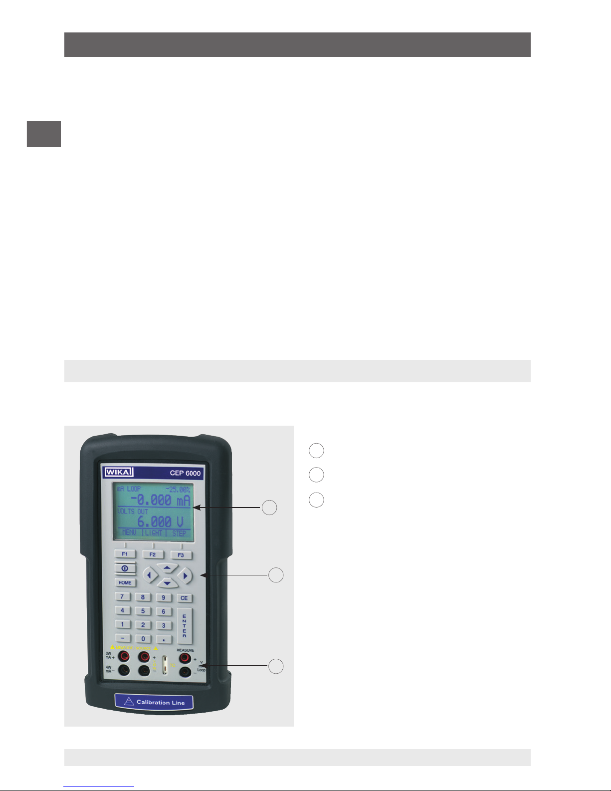
2. Short overview
2.1 Overview
Display
Keypad
Connections
1
2
3
1. General information / 2. Short overview
Page 7

7
WIKA operating instructions, model CEP6000
MM/YYYY country code based on 10/2014 GB/CN
GB
2.2 Description
The model CEP6000 hand-held multi-function calibrator is a battery-operated hand-held
instrument which can measure or simulate electrical parameters.
The model CEP6000 works with different thermocouples and resistance thermometers,
among others.
Very high accuracy and diverse special functions make the instrument to a user-friendly
and highly flexible calibration instrument.
2.3 Scope of delivery
■
Hand-held multi-function calibrator model CEP6000
■
Operating instructions
■
Test cables, three sets (red/black)
■
3.1 calibration certificate per DIN EN 10204
■
Four AA batteries
■
Protective rubber boot
■
Quick Start Guide
Cross-check scope of delivery with delivery note.
2. Short overview
Page 8

8
WIKA operating instructions, model CEP6000
MM/YYYY country code based on 10/2014 GB/CN
GB
3. Safety
3.1 Explanation of symbols
WARNING!
... indicates a potentially dangerous situation that can result in serious
injury or death, if not avoided.
CAUTION!
... indicates a potentially dangerous situation that can result in light injuries
or damage to equipment or the environment, if not avoided.
DANGER!
... identifies hazards caused by electrical power. Should the safety instructions not be observed, there is a risk of serious or fatal injury.
Information
... points out useful tips, recommendations and information for efficient
and trouble-free operation.
3.2 Intended use
The model CEP6000 hand-held multi-function calibrator is a battery-operated hand-held
instrument which can measure and output/simulate current, voltage, resistance, RTD’s,
TC’s, frequency and pulses.
In addition, external pressure sensors/pressure modules can be connected which enable
pressure to measure with this calibrator. The WIKA model CPT6600 pressure modules
and the Mensor model CPT6100/CPT6180 precision pressure sensors are compatible
here.
This instrument is not permitted to be used in hazardous areas!
The instrument has been designed and built solely for the intended use described here,
and may only be used accordingly.
The technical specifications contained in these operating instructions must be observed.
Improper handling or operation of the instrument outside of its technical specifications
3. Safety
Page 9

9
WIKA operating instructions, model CEP6000
MM/YYYY country code based on 10/2014 GB/CN
GB
requires the instrument to be taken out of service immediately and inspected by an
authorised WIKA service engineer.
Handle electronic precision measuring instruments with the required care (protect from
humidity, impacts, strong magnetic fields, static electricity and extreme temperatures,
do not insert any objects into the instrument or its openings). Plugs and sockets must be
protected from contamination.
The manufacturer shall not be liable for claims of any type based on operation contrary to
the intended use.
3.3 Improper use
WARNING!
Injuries through improper use
Improper use of the instrument can lead to hazardous situations and
injuries.
▶
Refrain from unauthorised modifications to the instrument.
▶
Do not use the instrument within hazardous areas.
▶
Only use accessories provided by WIKA.
Any use beyond or different to the intended use is considered as improper use.
Do not use this instrument in safety or emergency stop devices.
3.4 Responsibility of the operator
The instrument is used in the industrial sector. The operator is therefore responsible for
legal obligations regarding safety at work.
The safety instructions within these operating instructions, as well as the safety, accident
prevention and environmental protection regulations for the application area must be
maintained.
3. Safety
Page 10

10
WIKA operating instructions, model CEP6000
MM/YYYY country code based on 10/2014 GB/CN
GB
3.5 Personnel qualification
WARNING!
Risk of injury should qualification be insufficient
Improper handling can result in considerable injury and damage to equipment.
▶
The activities described in these operating instructions may only be
carried out by skilled personnel who have the qualifications described
below.
Skilled personnel
Skilled personnel, authorised by the operator, are understood to be personnel who,
based on their technical training, knowledge of measurement and control technology and
on their experience and knowledge of country-specific regulations, current standards and
directives, are capable of carrying out the work described and independently recognising
potential hazards.
Special operating conditions require further appropriate knowledge, e.g. of aggressive
media.
3.6 Labelling, safety marks
Product label
The product label is located on the side of the instrument beneath the protective rubber
boot.
Binary code
Serial no.
3. Safety
Page 11

11
WIKA operating instructions, model CEP6000
MM/YYYY country code based on 10/2014 GB/CN
GB
Symbols
Before commissioning the instrument, ensure you read the operating
instructions!
Instruments bearing this mark comply with the relevant European directives.
This marking on the instruments indicates that they must not be disposed
of in domestic waste. The disposal is carried out by return to the manufacturer or by the corresponding municipal authorities (see EU directive
2002/96/EC).
4. Design and function
The model CEP6000 hand-held multi-function calibrator is a battery-operated hand-held
instrument which can measure and output/simulate current, voltage, resistance, RTD’s,
TC’s, frequency and pulses.
In addition, external pressure sensors/pressure modules can be connected which enable
pressure to measure with this calibrator. The WIKA model CPT6600 pressure modules
and the Mensor model CPT6100/CPT6180 precision pressure sensors are compatible
here.
4.1 Front foil
The following figures show the location of the input and output terminals and also the
positions of the buttons on the calibrator.
3. Safety / 4. Design and function
Page 12

12
WIKA operating instructions, model CEP6000
MM/YYYY country code based on 10/2014 GB/CN
GB
F1
HOME
7
F2 F3
89CE
E
N
T
E
R
4
1
MEASURE / SOURCE
3W
mA+
TC
V
mA
Loop
+
V
Hz
–
+
–
5
2
0
6
3
.
4W
mA–
MEASURE
–
CEP6000
Ω
1
2
3
4
6
8
9
7 5
4.1.1 Connections
1
Connection for external pressure module
Connects the calibrator with a pressure module for pressure measurement.
2
Serial interface
Connects the calibrator with a PC for remote operation.
3
+
4
(Isolated) Current and voltage input as well as for output of DC 24 V voltage
supply
Terminals for the measurement of current, voltage and separate current loop supplies.
5
Thermocouple input/output
Terminal for the measurement or simulation of thermocouples. Suitable for polarised
miniature connectors for thermocouples.
6
+
7
Voltage, resistance thermometers (2-wire), frequency, pulse, input/output
Terminals for the simulation and measurement of voltage, frequency, pulse trains and
resistance thermometers (RTDs).
8
+
9
Current, resistance thermometers (3-wire, 4-wire), input/output
Terminals for the simulation and measurement of current and also for resistance thermometer measurements with 3- and 4-wire connection.
4. Design and function
Page 13
13
WIKA operating instructions, model CEP6000
MM/YYYY country code based on 10/2014 GB/CN
GB
F1
HOME
7
F2 F3
89CE
E
N
T
E
R
4
1
MEASURE / SOURCE
3W
mA+
TC
V
mA
Loop
+
V
Hz
–
+
–
5
2
0
6
3
.
4W
mA–
MEASURE
–
CEP6000
Ω
1
2
3
4
6
8
7
5
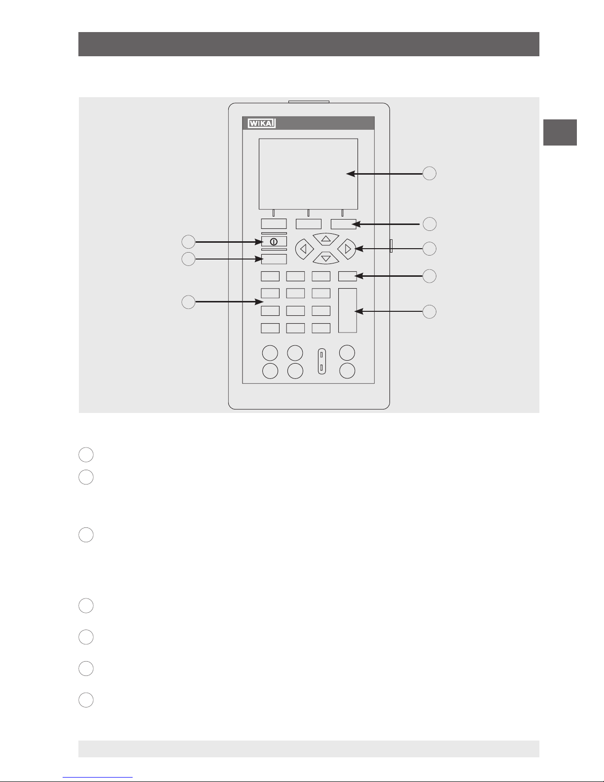
4.1.2 Key function
1
Display
2
Function keys, used to operate the menu bar at the bottom of the calibrator display
The [F1] key acts to select the options in the left-hand box, the [F2] key acts for the selection of
the functions in the middle box and the [F3] key for the selection of the functions in the righthand box.
3
Modification of individual digits of the output value; increase, decrease or ramp output
value
Use the left and right arrow buttons to select which digit in the output value should be changed.
With the up and down arrow keys, the output value can be increased, decreased or changed to
a ramp form.
4
Clear the input value
The last numerical value input will be deleted.
5
ENTER
Confirms the input of numerical values.
6
Numeric keys
Used for the input of numerical values.
7
HOME, returns to main menu
Reverts back to the start menu on the menu bar.
4. Design and function
Page 14
14
WIKA operating instructions, model CEP6000
MM/YYYY country code based on 10/2014 GB/CN
GB
8
ON/OFF
Switches the calibrator on and off.
4.2 Batteries
4.2.1 Selecting the batteries or rechargeable batteries
The model CEP6000 works with four alkaline batteries (AA) or with four NiMH
rechargeable batteries (AA).
4.2.2 Using the power supply unit
CAUTION!
Physical injuries and damage to property and the environment
If alkaline batteries are used in the model CEP6000 hand-held multifunction calibrator, when the power supply unit is used at the same time,
overheating, severe damage and leakage can occur. Leakage of electrolyte from batteries presents a significant health risk.
▶
Only ever use the power supply unit without batteries or with NiMH
rechargeable batteries in the instrument.
▶
Only use undamaged and fault-free power supply units.
▶
Use WIKA accessories.
Using the power supply unit:
1. Remove alkaline batteries from the model CEP6000 hand-held multi-function
calibrator or insert rechargeable batteries in the calibrator’s compartment.
2. Connect the power supply unit to the calibrator.
3. Insert the power cord into the power connector.
Ensure that the correct power supply is present when doing this.
The NiMH rechargeable batteries in the instrument are recharged slowly.
Recharging takes between approx. 10 and 12 hours.
4. After use, disconnect the power cord from the mains and the calibrator.
4. Design and function
Page 15

15
WIKA operating instructions, model CEP6000
MM/YYYY country code based on 10/2014 GB/CN
GB
5. Transport, packaging and storage
5.1 Transport
Check the model CEP6000 hand-held multi-function calibrator for any damage that may
have been caused by transport.
Obvious damage must be reported immediately.
CAUTION!
Damage through improper transport
With improper transport, a high level of damage to property can occur.
▶
When unloading packed goods upon delivery as well as during
internal transport, proceed carefully and observe the symbols on the
packaging.
▶
With internal transport, observe the instructions in chapter 5.2 “Packaging and storage”.
If the instrument is transported from a cold into a warm environment, the formation of
condensation may result in instrument malfunction. Before putting it back into operation,
wait for the instrument temperature and the room temperature to equalise.
5.2 Packaging and storage
Do not remove packaging until just before use.
Keep the packaging as it will provide optimum protection during transport (e.g. change in
place of use, sending for repair).
Permissible conditions at the place of storage:
■
Storage temperature: -20 ... +70 °C
■
Humidity: 0 ... 90 % relative humidity (non-condensing)
Avoid exposure to the following factors:
■
Direct sunlight or proximity to hot objects
■
Mechanical vibration, mechanical shock (putting it down hard)
■
Soot, vapour, dust and corrosive gases
■
Hazardous environments, flammable atmospheres
5. Transport, packaging and storage
Page 16

16
WIKA operating instructions, model CEP6000
MM/YYYY country code based on 10/2014 GB/CN
GB
Store the model CEP6000 hand-held multi-function calibrator in its original packaging in
a location that fulfils the conditions listed above. If the original packaging is not available,
pack and store the instrument as described below:
1. Wrap the instrument in an antistatic plastic film.
2. Place the instrument, along with shock-absorbent material, in the packaging.
3. If stored for a prolonged period of time (more than 30 days), place a bag containing a
desiccant inside the packaging.
6. Commissioning, operation
ATTENTION!
Damage through electric shock
Higher voltages than the rated voltage can cause damage to the multifunction calibrator. With any damage to the case or the test cables, an
electric shock can result from any contact.
▶
Apply the correct rated voltage, see chapter 10 “Specifications”.
▶
Do not use the calibrator if it is damaged. Prior to use check the case of
the calibrator. Pay attention to missing plastic components and cracks,
in particular to the insulation around the connections.
▶
Do not use the calibrator in case of malfunction. The instrument
protection might be compromised. In case of doubt, have the calibrator
checked.
▶
The battery compartment must be closed and sealed.
▶
Change the batteries as soon as the battery symbol is displayed.
▶
Always use the correct connector sockets, functions and measuring
ranges for the measurement or simulation.
▶
Only open the battery compartment once all cable connections have
been disconnected from the calibrator.
▶
Check the test cables for damaged insulation or bare metal components. Test the continuity of the test cables. Replace any damaged test
cable before using the calibrator.
▶
Do not touch the metal parts at the test cables.
As soon as the model CEP6000 hand-held multi-function calibrator is turned on, by
pressing the ON/OFF key, it will go through a short self-test routine. During this routine,
the display shows the current firmware version and the auto-shutdown status. The
calibrator requires a maximum of 5 minutes warm-up to reach its specified accuracy.
Large changes in ambient temperature may make a longer warm-up period necessary.
5. Transport, packaging and storage / 6. Commissioning, ...
Page 17
17
WIKA operating instructions, model CEP6000
MM/YYYY country code based on 10/2014 GB/CN
GB
mA IN
0.000 mA
-25.00%
RTD IN 4W P10-385
MENU
-OL °C
LIGHT
2
3
4
7
6
5
1
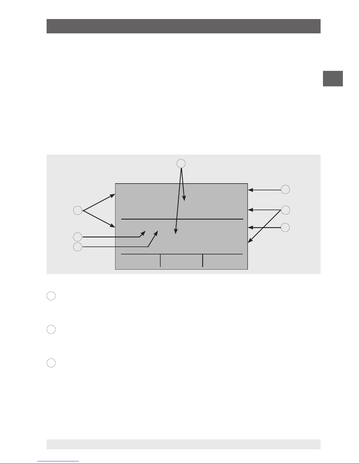
6.1 Main display
The display of the multi-function calibrator is subdivided into 3 main sections: the upper
display, the lower display and the menu bar.
■
The upper display is used for the measurement of direct current voltages, direct
current (with or without loop voltage) and for pressure measurement.
■
The lower display can be used both for measurement and for simulation.
■
The menu bar (at the bottom of the display) serves for configuration of the upper and
lower display (according to the desired function).
The following figure shows the location of the various display fields, which are described
in the table.
Numeric display
Displays the numeric value of the measured or simulated signals.
A measurement “OL” or “-OL” signals a value outside of the measuring range.
Display of the span
Only for the display “mA” and “mA LOOP”.
Displays the current measured value with respect to 4 mA = 0 % and 20 mA = 100 %.
Units
Displays the corresponding unit for measurement or output/simulation.
For “RTD” (resistance thermometer) and “TC” (thermocouple), °C or °F are offered; for
“FREQ” (frequency) and “PULSE” (pulse), CPM, Hz or kHz.
1
2
3
6. Commissioning, operation
Page 18

18
WIKA operating instructions, model CEP6000
MM/YYYY country code based on 10/2014 GB/CN
GB
Sensor type
For measurements and simulation of various resistance thermometers (RTDs) and
thermocouples (TCs).
All possible sensor types are stated in the specifications (see chapter 10
“Specifications”). The options also show the amplitude of the pulse or frequency
simulation and the pressure unit.
Additional settings
Only available for the option “TC measurement” (thermocouple) and “RTD
measurement” (resistance thermometer).
With the option “TC”, this setting switches the cold junction compensation (CJC) on or
off.
With RTD measurements, this setting defines the number of wires for the
measurement (2W = 2-wire measurement, 3W = 3-wire measurement, 4W = 4-wire
measurement).
Input/output display
Switches the lower display between input mode (measuring) and output mode
(output/simulation).
Primary parameters
Defines which parameter will be measured or outputted/simulated.
The available options for the upper display are: “VOLTS IN” (input voltage),
“PRESSURE” (pressure), “mA IN” (input current in mA) and “mA LOOP” (mA with
DC 24 V voltage supply).
The available options for the lower display are: “VOLTS” (voltage), “TC”
(thermocouple), “RTD” (resistance thermometer), “FREQ” (frequency), “PULSE”
(pulse), “PRESSURE” (pressure) and “mA” (current) or “mA 2W SIM” (current
simulation).
6.2 Menu bar
The display parameters are managed via the menu bar, which is found along the bottom
of the LCD display. The function keys [F1], [F2] and [F3] enable navigation through all
levels and options of the menu bar. The upper menu level is the start menu.
One can return to this at any time with the [HOME] key. There are three variants of the
start menu: the input start menu, the output start menu and the pulse start menu.
6.2.1 Menu function “Measuring”
In the start menu for the function “Measuring”, only the options “MENU” and “LIGHT” are
active. The option “MENU” calls the next menu level to the menu bar, i.e. to call the main
4
5
6
7
6. Commissioning, operation
Page 19

19
WIKA operating instructions, model CEP6000
MM/YYYY country code based on 10/2014 GB/CN
GB
menu. Press the corresponding function key, [F1], to call the main menu.
The option “LIGHT” switches on the backlight for the LCD display. Press the corresponding function key [F2] to switch on the backlighting.
6.2.2 Menu function “Output”
In the start menu for the function “Output” there are three active options “MENU”, “LIGHT”
and “STEP” or “RAMP”.
The first two options work just like in the start menu. The third option can be selected
via the automatic output function menu option, and acts to switch on or off the selected
automatic function. For further information, see chapter 6.5.2 “Using the automatic output
functions”. The automatic output functions are stopped as soon as the menu is exited or
the [HOME] key is pressed.
6.2.3 Menu function “Pulse output”
The pulse start menu also has three active options, “MENU”, “TRIG” and “COUNTS”.
The options “TRIG” and “COUNTS” are used for pulse simulation. The function of these
options is explained in chapter 6.5.7 “Pulse output”.
6.2.4 Menu function “UPPER”, “LOWER” and “MORE”
The next level of the menu bar is the main menu itself. Which levels are available under
the main menu depends on the selected operating mode of the calibrator. The options are
“UPPER”, “LOWER” and “MORE”.
With “UPPER”, the selection menu for the parameters of the upper display will be called.
With “LOWER”, the selection menu for the parameters of the lower display will be called.
“MORE” switches to the next menu level.
MENU LIGHT
MENU LIGHT STEP
MENU TRIG
COUNTS
UPPER LOWER MORE
6. Commissioning, operation
Page 20

20
WIKA operating instructions, model CEP6000
MM/YYYY country code based on 10/2014 GB/CN
GB
6.2.5 Menu function “Automatic output function”
The “Automatic output function” is a menu function in the “Output” mode and is called by
pressing “MORE”. The options are “AUTO FUNC”, “NEXT” and “DONE”.
With “AUTO FUNC” the parameters of the automatic output function can be set. “NEXT”
switches to the next menu function and “DONE” returns to the start menu. For further
information, see chapter 6.5.2 “Using the automatic output functions”.
6.2.6 Menu function “Contrast”
The next menu level is the contrast menu. The options are “CONTRAST”, “NEXT” and
“DONE”.
The option “CONTRAST” acts to set the contrast. “NEXT” switches to the next menu
function and DONE returns to the start menu. The contrast can be set with the arrow keys
[F1, F2], which are displayed after selecting the option “CONTRAST”.
In certain cases, large changes in contrast can make the display difficult to read under
normal conditions. If the display is too bright or too dark for the values to be read, the
following steps should be taken in order to reset the contrast setting to the default.
1. Turn the instrument on while holding the [HOME] key down.
2. Hold this button down for 10 seconds in order to reset the factory settings for the
contrast. If the display is so light that it is not possible to see whether the instrument is
switched on or off, use the button for the backlighting as an indication of this.
6.2.7 Menu function “Automatic switch-off”
The main menu for the automatic switch-off contains the options “AUTO OFF”, “NEXT”
and “DONE”.
The option “AUTO OFF” acts to switch on and off the automatic switch-off function and
specifies how long the instrument remains in standby before it switches off. “NEXT”
switches to the next menu function and “DONE” returns to the start menu.
AUTO FUNC
NEXT DONE
CONTRAST
NEXT DONE
AUTO OFF NEXT DONE
6. Commissioning, operation
Page 21

21
WIKA operating instructions, model CEP6000
MM/YYYY country code based on 10/2014 GB/CN
GB
6.2.8 Menu function “Frequency or pulse output”
When the lower display is used for frequency or pulse outputs, in addition, the sub-menu
for frequency is displayed after the main menu. The options are “FREQ LEVEL”, “NEXT”
and “DONE”.
The option “FREQ LEVEL” enables the setting of the amplitude of the oscillation. “NEXT”
switches to the next menu function and “DONE” returns to the start menu.
6.2.9 Menu function “Probe-specific coefficients”
If the calibrator is working in the “RTD CUSTOM” mode, following the main menu,
the RTD menu for the user-defined configuration is displayed. The options are “SET
CUSTOM”, “NEXT” and “DONE”.
The option “SET CUSTOM” enables the input of the coefficients of a user-defined “PRT”
(platinum resistance thermometer) into the calibrator. “NEXT” switches to the next menu
function and “DONE” returns to the start menu.
6.2.10 Menu function “ZERO”
Resetting the pressure to the zero value is the final option on selecting “MORE” in the
main menu and is only shown if an external pressure sensor is connected. The options
are “ZERO”, “NEXT” and “DONE”.
The option “ZERO” acts to reset the pressure to zero. “NEXT” switches to the next menu
function and “DONE” returns to the start menu. For further information on resetting to 0,
see chapter 6.4.4 “Measuring pressure”.
FREQ LEVEL
NEXT DONE
SET CUSTOM
NEXT DONE
ZERO NEXT DONE
6. Commissioning, operation
Page 22

22
WIKA operating instructions, model CEP6000
MM/YYYY country code based on 10/2014 GB/CN
GB
MEASURE / SOURCE
3W
mA+
TC
V
mA
Loop
+
V
Hz
–
+
4W
mA–
MEASURE
–
–
+
Ω
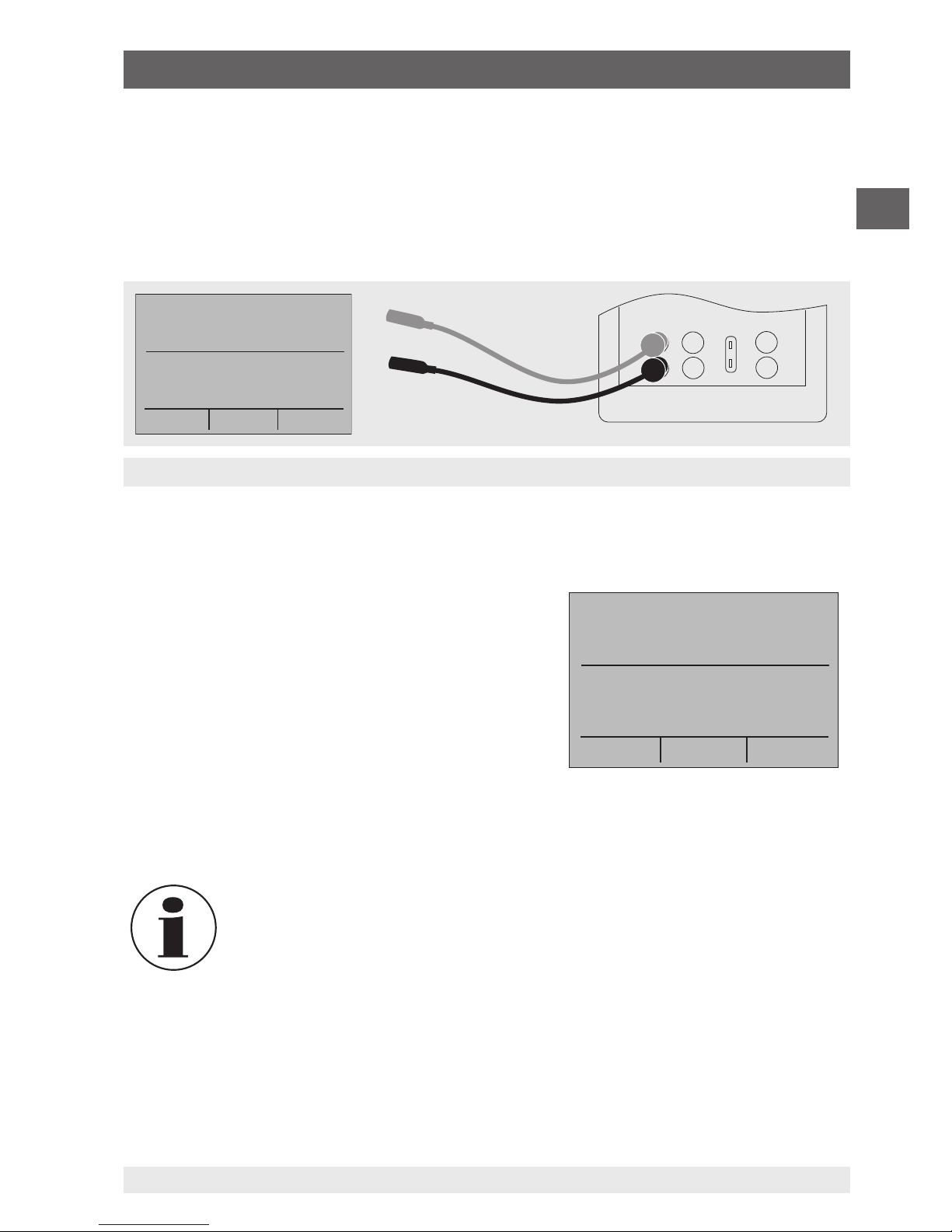
VOLTS IN
-0.000 V
VOLTS IN
MENU
5.000 V
LIGHT
Measuring voltage and frequency with the input and output terminals
6.2.11 Menu function “Parameter selection”
The menu for parameter selection is called via the main menu using “UPPER” or
“LOWER”. The options are “SELECT”, “NEXT” and “DONE”. When selected, one parameter flashes in the display.
Using the option “SELECT”, the parameter can be altered. With the option “NEXT”, one
can switch to another variable. “DONE” switches back to the start menu and accepts the
selection.
6.3 Cursor control/set point control
The output value can be changed using the four arrow keys on the keypad. If an arrow key
is pressed, a cursor appears under the last digit of the output value. Use the left and right
arrow buttons to select which digit in the output value should be changed. With the up
and down arrow keys, the output value can be increased or decreased. The menu bar will
change to the set point menu, as soon as one of the four arrow keys is pressed.
The three function keys are assigned the values “0 %”, “25 %” and “100 %”. The value for
0 and 100 % can be saved through the input of a value, when the corresponding function
key is held down at the same time. The key for “25 %” then switches to the value corresponding to 25 %.
6.4 Using the measuring modes (lower display)
6.4.1 Measuring voltage and frequency
To measure voltage or frequency, follow the steps below:
1. In the main menu, switch to the lower display “LOWER” and select “V” or “FREQ”.
2. The input/output setting must be set to “IN”.
3. Connect the test cables (see following figure).
SELECT NEXT DONE
0% 25% 100%
6. Commissioning, operation
Page 23
23
WIKA operating instructions, model CEP6000
MM/YYYY country code based on 10/2014 GB/CN
GB
MEASURE / SOURCE
3W
mA+
TC
V
mA
Loop
+
V
Hz
–
+
4W
mA–
MEASURE
–
–
+
Ω
mA IN
0.000 mA
-25.00%
mA IN
MENU
5.000 mA
LIGHT
Measurement of the current in mA at the input and output
terminals
6.4.2 Measuring current (mA)
To measure current in mA, follow the steps below:
1. In the main menu, switch to the lower display “LOWER” and select “mA”.
2. The input/output setting must be set to “IN”.
3. Connect the test cables (see following figure).
6.4.3 Measuring temperature
6.4.3.1 Using thermocouples
The calibrator supports the following types of
thermocouples: B, C, E, J, K, L, N, R, S, T, U, BP and
XK. The typical characteristics of all of these types
are described in chapter 10 “Specifications”. The
calibrator also has a “CJC” (cold junction compensation) function. In normal operation, the function
will be activated, and it will measure the effective
temperature of the thermocouple. If the option “CJC”
is deactivated, the calibrator measures the difference between the thermocouple at the connection point and the input terminal of the
thermocouple.
The CJC option should only be deactivated when the calibration is being
made with an external ice bath.
To measure temperature with the thermocouple, follow the steps below:
1. Connect the wires of the thermocouple to the input/output of the calibrator using the
thermocouple mini-connector (see following figure).
mA IN
0.000 mA
-25.00%
TC IN CJC OFF B
MENU
OL °C
LIGHT
6. Commissioning, operation
Page 24
24
WIKA operating instructions, model CEP6000
MM/YYYY country code based on 10/2014 GB/CN
GB
MEASURE / SOURCE
3W
mA+
TC
V
mA
Loop
+
V
Hz
–
+
4W
mA–
MEASURE
–
+
–
Ω
Measurement of the temperature at the thermocouple terminal
Thermocouple plug
The connecting cable for the thermocouple must match the type of the
thermocouple being calibrated.
2. In the main menu, switch to the lower display “LOWER” and select “TC”.
3. The input/output setting must be set to “IN”.
4. Select the corresponding thermocouple model in the menu.
5. Select temperature unit.
In the interests of optimum accuracy, wait 2 to 5 minutes so that the
temperature between the mini-connector and the calibrator stabilises.
After this, carry out the measurement.
The calibrator can measure the voltage of the thermocouple in mV, so that the temperature can be determined with the aid of a table if the corresponding thermocouple type is
not supported by the calibrator. For the case described above, proceed and select “mV”
as the type.
6.4.3.2 Using resistance thermometers (RTDs)
The supported resistance thermometers are detailed in the specifications in chapter
10 “Specifications”. The specific characteristic of RTDs is their temperature-dependent
resistance (R0). The calibrator can work with input signals with 2-, 3- or 4-wires, where
input measurements with 4-wire connection are the most accurate.
To measure temperature with resistance thermometers, follow the steps below:
1. In the main menu, switch to the lower display “LOWER” and select “RTD”.
2. The input/output setting must be set to “IN”.
3. Select 2-, 3- or 4-wire connection “2W, 3W, 4W”.
6. Commissioning, operation
Page 25

25
WIKA operating instructions, model CEP6000
MM/YYYY country code based on 10/2014 GB/CN
GB
MEASURE / SOURCE
3W
mA+
TC
V
mA
Loop
+
V
Hz
–
+
4W
mA–
MEASURE
–
–
+
–
+
–
+
–
+
–
+
–
+
3W
4W
RTD
RT
D
RT
D
2W
Ω
mA IN
0.000 mA
-25.00%
RTD IN 4W P10-385
MENU
25.0 °C
LIGHT
Measuring the temperature with RTD probe connected
4. Select the corresponding RTD type in the menu.
5. Select temperature unit.
6. Connect the RTD wires (see following figure).
The resistance can also be measured with this function. For this, follow the steps as
described above, and as RTD type, select “OHMS”. With this option and a measurement table, an RTD probe that is not programmed into the calibrator can also be used for
measurement.
6.4.4 Measuring pressure
CAUTION!
Pressurisation
Damage within the pressure system due to open valves.
1. Close the valve.
2. Release the pressure slowly.
3. Connect the pressure module to the pressure line.
ATTENTION!
Damage to the threaded connections
The pressure module can be damaged by over-tightening the threaded
connection.
▶
Use suitable tools.
▶
Tighten the pressure connection with a maximum of 13.6 Nm (torque
spanner).
6. Commissioning, operation
Page 26

26
WIKA operating instructions, model CEP6000
MM/YYYY country code based on 10/2014 GB/CN
GB
F1
HOME
7
F2 F3
89CE
E
N
T
E
R
4
1
MEASURE / SOURCE
3W
mA+
TC
V
mA
Loop
+
V
Hz
–
+
–
5
2
0
6
3
.
4W
mA–
MEASURE
–
CEP6000
Ω
Connection for pressure measurement
Valve
Pressure
module
Pressure module
adapter
▶
Never exceed the permissible maximum pressure.
▶
Only use pressure modules with compatible media. See specification of
the pressure module.
To measure pressure with external pressure modules, follow the steps below:
1. Connect the pressure module to the calibrator using the pressure module adapter (see
following figure).
For the connection of the pressure module to the calibrator, a WIKA
pressure module adapter must be used.
2. From the main menu, switch to the upper or lower display as required. The calibrator
measures pressure in the upper as well as the lower display. In this way, pressure can
be measured on two different units at the same time.
3. As the primary parameter, select “PRESSURE”.
4. Select the desired unit of measure.
■
With high-pressure modules, technical units of measure that are only
used for low pressure ranges, such as inH2O, cmH2O, etc., are not
valid selections. If one of these units is selected with a high-pressure
module connected, “----” is shown on the display.
5. Set the pressure module to zero (ZERO). The function to reset the calibrator is found
under the menu function “ZERO”.
6. Commissioning, operation
Page 27

27
WIKA operating instructions, model CEP6000
MM/YYYY country code based on 10/2014 GB/CN
GB
6.4.4.1 Zeroing of absolute pressure modules
To reset the calibrator to zero, set it so that it measures a known pressure, for example the
barometric pressure.
To zero the calibrator, follow the steps below:
1. Call up the menu function “ZERO”.
2. Select “ZERO”. “SET REFERENCE ABOVE” will
be displayed.
3. Enter the reference pressure via the keypad.
The calibrator saves the barometric reference value
in permanent memory. The reference value will
always be saved for an absolute pressure module. If
a new absolute pressure module is connected, this
procedure must be repeated.
6.5 Using the output modes (lower display)
The calibrator can generate signals for testing and calibrating process instruments. It can
simulate voltage, current, resistance, frequency, pulses and the electrical output signal of a
resistance thermometer or a thermocouple.
6.5.1 Setting the output parameters 0 % and 100 %
To enter the 0 % and 100 % points, follow the steps below:
1. Select the lower display “LOWER” from the main menu and then select the required
function.
2. Select the output “OUT” at the input/output setting and enter the desired value.
(example: “VOLTS OUT”).
3. On the keypad, enter (for example) 5 V and press the enter key.
4. Press one of the arrow keys in order to select the set point setting from the menu.
5. Hold down the function key for “0 %” [F1]. The value 0 % will flash for a short time and
the set point (e.g. 5 V) will be saved.
6. Repeat these steps with (for example) 20 V and hold down the function key for “100 %”
[F3].
7. With the function key for “25 %”, it is now possible to move between 5 V and 20 V in
steps of 25 %.
PRESSURE
-------
psi
PRESSURE mbar
MENU
-------
LIGHT
6. Commissioning, operation
Page 28

28
WIKA operating instructions, model CEP6000
MM/YYYY country code based on 10/2014 GB/CN
GB
mA LOOP
0.000 mA
-25.00 %
mA OUT
MENU
5.000 mA
LIGHT
–
+
UUT
MEASURE / SOURCE
3W
mA+
TC
V
mA
Loop
+
V
Hz
–
+
4W
mA–
MEASURE
–
Ω
Connection for use as a mA source
6.5.1.1 Increasing the output current in steps
To use the 25 % function with an output signal in the milliampere range, follow the
steps below:
1. Select the option “mA” for the lower display from the main menu.
2. With the key for “25 %”, it is possible to move between 4 mA and 20 mA in intervals of
25 %.
6.5.2 Using the automatic output functions
The step function and automatic ramp function are available as automatic output
functions. The selected function can be switched on and off via the start menu (“STEP” or
“RAMP”). The automatic output parameters can be set in the menu via “Automatic output
function”.
The parameters include:
■
Which automatic output function is available (step function or ramp function).
■
The time for the automatic output function defines the time between the individual
steps or, in the ramp function, the time between the first and second limit value in the
ramp.
■
The limit values for the ramp mode and step function are set to 0 % and 100 %. For
further information, see chapter 6.5.1 “Setting the output parameters 0 % and 100 %”.
The step increase is made in 25 % steps from 0 % to 100 %.
6.5.3 Current output
To output a current, follow the steps below:
1. In the main menu, switch to the lower display “LOWER” and select “mA”.
2. The input/output setting must be set to “OUT”.
3. Connect the test cables to the terminals for current output (see following figure).
4. Enter the desired current value via the keypad.
6. Commissioning, operation
Page 29
29
WIKA operating instructions, model CEP6000
MM/YYYY country code based on 10/2014 GB/CN
GB
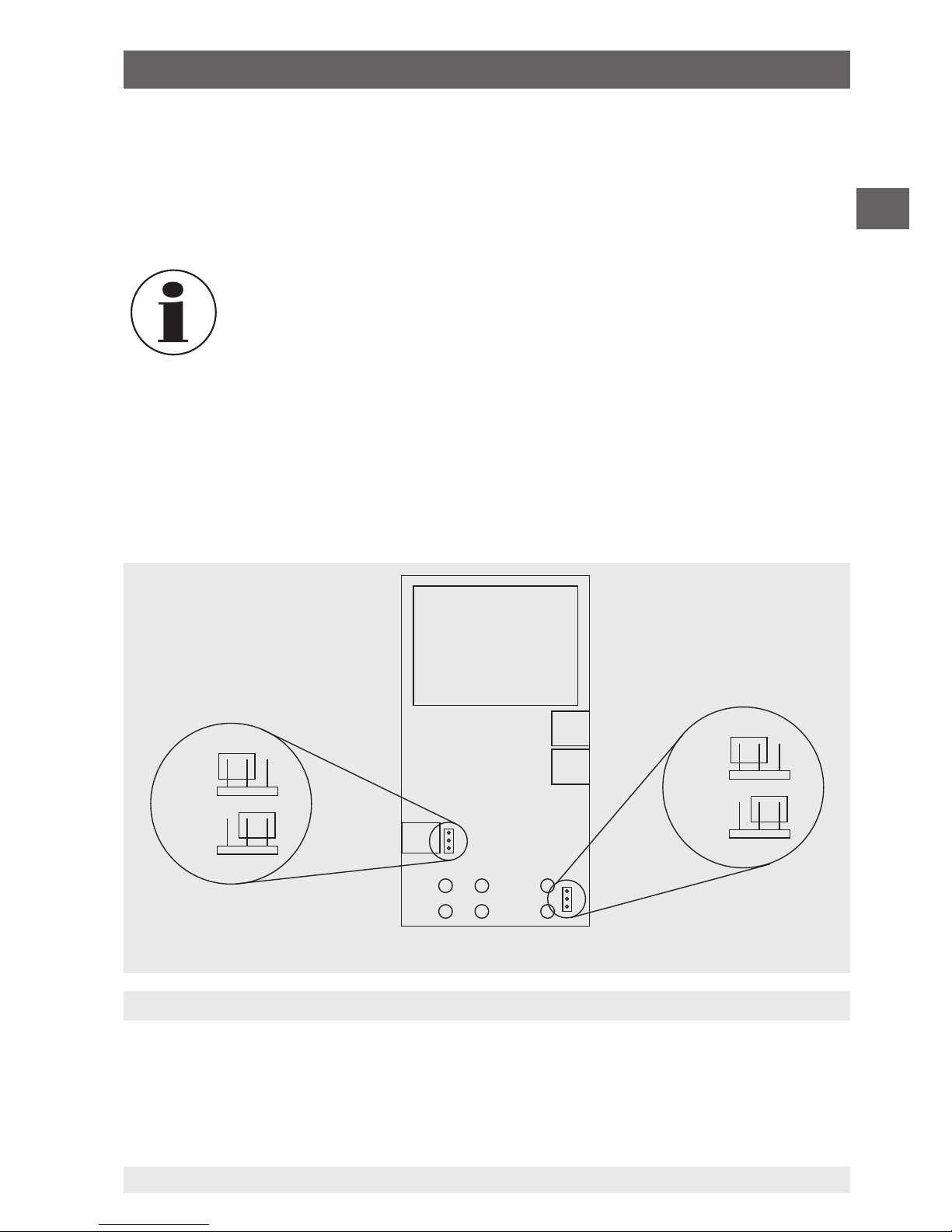
Position of the HART™ jumpers
HART™ resistor
Circuit board
6.5.3.1 HART™ resistor selection
The CEP6000 can be configured so that the 250 Ω resistor for HART™ compatible
instruments can be activated within the CEP6000. If the internal 250 Ω resistor within the
CEP6000 is used, a serial resistance for the calibration of HART™ modules must not be
activated.
When using the internal 250 Ω resistor, the maximum load resistance is
reduced from 1,000 Ω to 750 Ω, at a current of 20 mA.
6.5.3.2 HART™ resistor, activation/deactivation procedure
1. Remove the battery cover and loosen both of the screws on the upper part of the case.
2. Remove both of the screws on the lower part of the case.
3. Carefully remove the upper half of the case from the lower half.
The following picture indicates the position of the HART™ jumpers.
6. Commissioning, operation
OFF
OFF
ON
ON
Page 30

30
WIKA operating instructions, model CEP6000
MM/YYYY country code based on 10/2014 GB/CN
GB
–
+
UUT
MEASURE / SOURCE
3W
mA+
TC
V
mA
Loop
+
V
Hz
–
+
4W
mA–
MEASURE
–
Ω
mA LOOP
0.000 mA
-25.00%
mA OUT
MENU
6.000 V
LIGHT
MEASURE / SOURCE
3W
mA+
TC
V
mA
Loop
+
V
Hz
–
+
4W
mA–
MEASURE
–
–
–
+
+
UUT
Ω
mA IN
0.000 mA
-25.00%
mA 2W SIM
MENU
4.000 mA
LIGHT
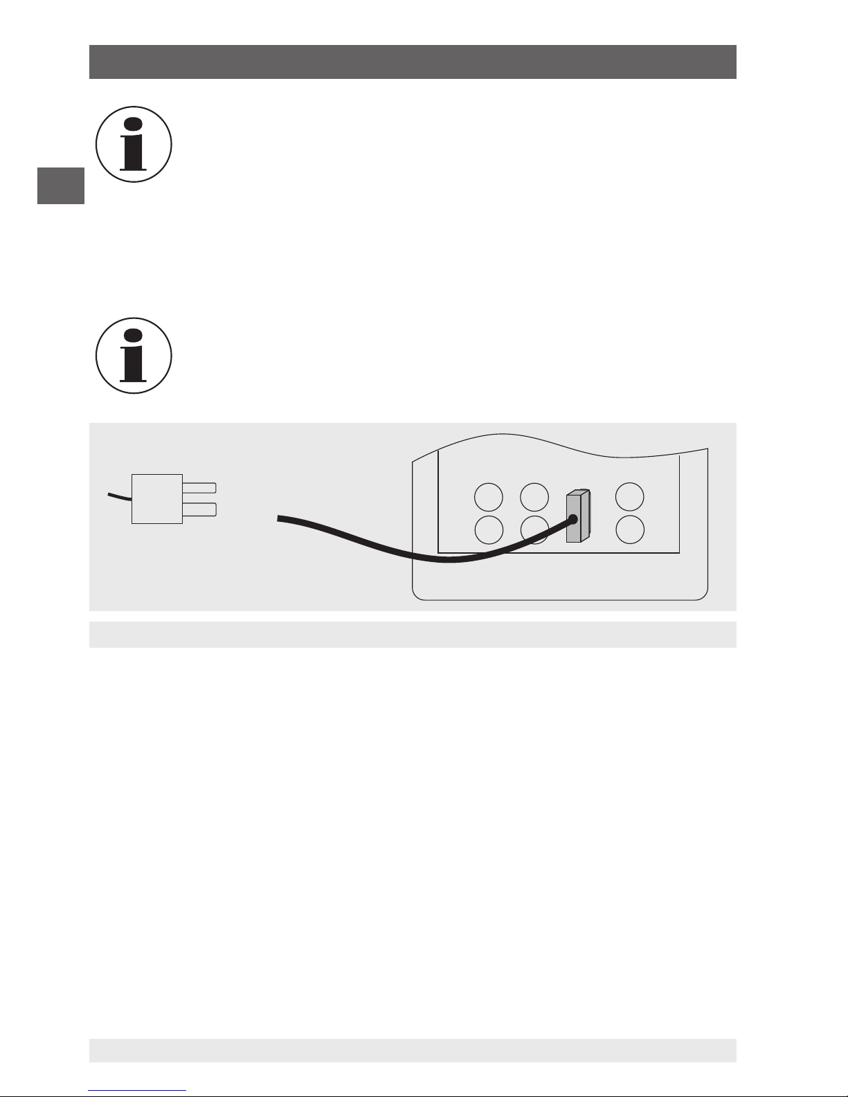
Connection for the transmitter simulation
Connections for voltage, frequency and pulse outputs
30 V max.
Voltage
supply
6.5.4 Simulating a transmitter
To use the calibrator to simulate a transmitter in a current loop, follow the steps
below:
1. In the main menu, switch to the lower display “LOWER” and select “mA 2W SIM”.
2. Enter the desired current with the keypad.
3. Connect the test cables to the terminals for current input (see following figure).
3. Connect the external DC 24 V voltage supply (see following figure).
6.5.5 Voltage output
To output a voltage, follow the steps below:
1. In the main menu, switch to the lower display “LOWER” and select “VOLTS”.
2. The input/output setting must be set to “OUT”.
3. Connect the test cables to the terminals for voltage output (see following figure).
4. Enter the desired voltage value via the keypad.
6. Commissioning, operation
Page 31

31
WIKA operating instructions, model CEP6000
MM/YYYY country code based on 10/2014 GB/CN
GB
6.5.6 Frequency output
To output a frequency, follow the steps below:
1. In the main menu, switch to the lower display
“LOWER” and select “FREQ”.
2. The input/output setting must be set to “OUT”.
3. Set the corresponding frequency unit.
4. Connect the test cables to the terminals for
frequency output (see figure “Connections for
voltage, frequency and pulse outputs”).
5. Enter the desired frequency value via the keypad.
6. To change the amplitude, select the option
“FREQ LEVEL” in the menu function “Frequency or pulse output”.
7. Enter the desired amplitude value via the keypad.
6.5.7 Pulse output
The calibrator can generate a pulse train with an
adjustable number of pulses at a desired frequency.
As an example, if the frequency is set to 60 Hz and
the number of pulses set to 60, the calibrator will
generate 60 pulses in 1 second.
For operation as a pulse generator, the same
connections are used as for frequency “Output”.
To output a pulse, follow the steps below:
1. In the main menu, switch to the lower display “LOWER” and select “PULSE”.
2. Set the corresponding pulse unit.
3. Connect the test cables to the terminals for pulse output (see figure “Connections for
voltage, frequency and pulse outputs”).
4. With the function “COUNTS” in the start menu, the number of pulses is set. The signal
is started and stopped using the “TRIG” key.
5. To change the amplitude, select the option “FREQ LEVEL” in the menu function
“Frequency or pulse output”.
6.5.8 Simulating thermocouples
To simulate a thermocouple, follow the steps below:
1. Connect the wires of the thermocouple to the input/output of the calibrator using the
thermocouple mini-connector (see following figure).
2. In the main menu, switch to the lower display “LOWER” and select “TC”.
mA IN
0.000 mA
-25.00%
FREQ OUT
5.0 Vpp
MENU
4.0 kHz
LIGHT
mA LOOP
0.000 mA
-25.00%
PULSE
5.0 Vpp
MENU
5.0 kHz
TRIG COUNTS
6. Commissioning, operation
Page 32

32
WIKA operating instructions, model CEP6000
MM/YYYY country code based on 10/2014 GB/CN
GB
mA LOOP
0.000 mA
-25.00%
RTD OUT P500-385
MENU
10.0 °C
LIGHT
MEASURE / SOURCE
3W
mA+
TC
V
mA
Loop
+
V
Hz
–
+
4W
mA–
MEASURE
–
Ω
mA IN
0.000 mA
-25.00%
TC OUT CJC OFF
E
MENU
100.0 °C
LIGHT
MEASURE / SOURCE
3W
mA+
TC
V
mA
Loop
+
V
Hz
–
+
4W
mA–
MEASURE
–
–
+
+
–
Ω
Simulating the temperature at the thermocouple terminal
Simulating resistance or resistance thermometers
Thermocouple plug
3. The input/output setting must be set to “OUT”.
4. Select the corresponding thermocouple model in the menu.
5. Select temperature unit.
6. Enter the temperature value or voltage value, respectively, via the keypad.
Used thermocouple wire must match the thermocouple type being
calibrated.
6.5.9 Simulating resistance or resistance thermometers
To simulate a resistance/resistance thermometer, follow the steps below:
1. Connect the wires of the RTD type to the input/output of the calibrator (see following
figure).
2. In the main menu, switch to the lower display “LOWER” and select “RTD”.
3. The input/output setting must be set to “OUT”.
4. Select the corresponding RTD type in the menu.
5. Select temperature unit.
6. Enter the temperature value or resistance value, respectively, via the keypad.
6. Commissioning, operation
Page 33

33
WIKA operating instructions, model CEP6000
MM/YYYY country code based on 10/2014 GB/CN
GB
3W
4W
1
1
2
2
3
3
4
4
MEASURE / SOURCE
3W
mA+
TC
V
mA
Loop
+
V
Hz
–
+
4W
mA–
MEASURE
–
MEASURE / SOURCE
3W
mA+
TC
V
mA
Loop
+
V
Hz
–
+
4W
mA–
MEASURE
–
Ω Ω
3- or 4-wire connection for RTDs
Use stackable test
cables for common
terminals
The calibrator simulates an RTD probe with 2-wires. To connect a probe
with 3- or 4-wires, use the stackable test cables (see following figure).
6.5.9.1 Customer-specific resistance thermometer (RTD)
To achieve the highest possible accuracy, it is possible to load probe-specific resistance
thermometer coefficients into the calibrator.
To enter probe-specific coefficients, follow the steps below:
1. In the main menu, switch to the lower display “LOWER” and select “RTD”.
2. Select RTD type “CUSTOM”.
3. Select menu function “Probe-specific coefficients”.
4. Enter the values requested by the calibrator using the keypad.
▶
Minimum temperature
▶
Maximum temperature
▶
R
0
▶
Temperature coefficients
The custom function uses the Callendar–Van Dusen equation for output and measure-
ment of custom resistance thermometers. The coefficient C is used only for temperatures
6. Commissioning, operation
Page 34

34
WIKA operating instructions, model CEP6000
MM/YYYY country code based on 10/2014 GB/CN
GB
–
MEASURE / SOURCE
3W
mA+
TC
V
mA
Loop
+
V
Hz
–
+
4W
mA–
MEASURE
–
+
Isolated input
below 0 °C. For the range above 0 °C, only the coefficients A and B are required, so
coefficient C is then set to 0. R0 is the resistance of the probe at 0 °C.
Coefficients for Pt385, Pt3926 and Pt3616
RTD Range R0 Coefficient A Coefficient B Coefficient C
Pt385 -260 ... 0 °C 100 3.9083 x 10
-3
-5.775 x 10
-7
-4.183 x 10
-12
Pt385 0 ... 630 °C 100 3.9083 x 10
-3
-5.775 x 10
-7
-
Pt3926 Under 0 °C 100 3.9848 x 10
-3
-5.87 x 10
-7
-4 x 10
-12
Pt3926 Above 0 °C 100 3.9848 x 10
-3
-5.87 x 10
-7
-
Pt3916 Under 0 °C 100 3.9692 x 10
-3
-5.8495 x 10
-7
-4.2325 x 10
-12
Pt3916 Above 0 °C 100 3.9692 x 10
-3
-5.8495 x 10
-7
-
6.6 Using the isolated measuring modes (upper display)
6.6.1 Measuring voltage (V) or current (mA)
To measure voltage or current on the isolated input channel, follow the steps
below:
1. In the main menu, switch to the upper display “UPPER” and select “V” or “mA”.
2. Connect the test cables to the calibrator’s isolated inputs (see following figure).
6.6.2 Current measurement with DC 24 V voltage supply
To test a 2-wire transmitter, which has an external power supply that is not connected,
use the function for separate voltage supply. This function activates a DC 24 V voltage
supply in series with the measuring current loop.
6. Commissioning, operation
Page 35

35
WIKA operating instructions, model CEP6000
MM/YYYY country code based on 10/2014 GB/CN
GB
MEASURE / SOURCE
3W
mA+
TC
V
mA
Loop
+
V
Hz
–
+
4W
mA–
MEASURE
–
–
+
Ω
mA LOOP
0.000 mA
-25.00%
mA IN
MENU
-0.001 mA
LIGHT
MEASURE / SOURCE
3W
mA+
TC
V
mA
Loop
+
V
Hz
–
+
4W
mA–
MEASURE
–
Ω
Isolated input
Connection of a display instrument
Maximum current: 1 mA
To measure current with a DC 24 V voltage supply on the isolated input channel,
follow the steps below:
1. In the main menu, switch to the upper display “UPPER” and select “mA LOOP”.
2. Connect the test cables to the calibrator’s isolated inputs (see following figure).
6.7 Using the upper and lower displays for test and calibration
6.7.1 Calibrating a display instrument
To calibrate recording and display instruments using the output functions, follow
the steps below:
1. In the main menu, switch to the lower display “LOWER” and select the corresponding
parameter.
2. The input/output setting must be set to “OUT”.
3. Connect the test cables to the calibrator (see following figure).
6. Commissioning, operation
Page 36

36
WIKA operating instructions, model CEP6000
MM/YYYY country code based on 10/2014 GB/CN
GB
F1
HOME
7
F2 F3
89CE
E
N
T
E
R
4
1
MEASURE / SOURCE
3W
mA+
TC
V
mA
Loop
+
V
Hz
–
+
–
5
2
0
6
3
.
4W
mA–
MEASURE
–
CEP6000
Ω
–
+
Calibrating an I/P instrument
Pressure module
and pressure
module adapter
6.7.2 Calibrating an I/P instrument
To calibrate pressure-controlling instruments, follow the steps below:
1. In the main menu, switch to the upper display “UPPER” and select “PRESSURE”.
2. In the main menu, switch to the lower display “LOWER” and select “mA”.
3. The input/output setting must be set to “OUT”.
4. Connect the calibrator to the sensor using the mA output (see following figure).
5. Enter the current value via the keypad.
The calibrator simulates the transmitter current and measures the output
pressure with an external pressure module.
6.7.3 Calibrating a transmitter
To calibrate a transmitter, both displays (“UPPER” and “LOWER”) are used - the upper
display for measurement and the lower for output/simulation. In this example, a thermocouple transmitter is calibrated.
6. Commissioning, operation
Page 37

37
WIKA operating instructions, model CEP6000
MM/YYYY country code based on 10/2014 GB/CN
GB
MEASURE / SOURCE
3W
mA+
TC
V
mA
Loop
+
V
Hz
–
+
4W
mA–
MEASURE
–
Ω
Calibrating a TC temperature transmitter
To calibrate TC temperature transmitters, follow the steps below:
1. In the main menu, switch to the upper display “UPPER” and select “mA LOOP”.
2. In the main menu, switch to the lower display “LOWER” and select “TC”.
3. The input/output setting must be set to “OUT”.
4. Set the end values 0 % and 100 % with the keypad and the [0 %] and [100 %] keys
(also see chapter 6.5.1 “Setting the output parameters 0 % and 100 %”).
5. Connect the calibrator with the TC output to the TC input of the transmitter. In addition,
connect the calibrator, using its mA input, to the mA output of the transmitter (see
following figure).
6. Output a temperature value using the keypad or test 0-25-50-75-100 % using the 25 %
step function (25 % key).
To calibrate a different type transmitter, follow the steps above with the
exception of the selection of the lower display. Set the thermocouple with
the correct parameters for the transmitter.
6.7.4 Calibrating a pressure transmitter
To calibrate pressure transmitters, follow the steps below:
1. In the main menu, switch to the upper display “UPPER” and select “mA LOOP”.
2. In the main menu, switch to the lower display “LOWER” and select “PRESSURE”.
3. Connect the calibrator with the mA input to the mA output of the pressure transmitter.
In addition, connect the external pressure module with the pressure connection of the
6. Commissioning, operation
Page 38

38
WIKA operating instructions, model CEP6000
MM/YYYY country code based on 10/2014 GB/CN
GB
–
+
F1
HOME
7
F2 F3
89CE
E
N
T
E
R
4
1
MEASURE / SOURCE
3W
mA+
TC
V
mA
Loop
+
V
Hz
–
+
–
5
2
0
6
3
.
4W
mA–
MEASURE
–
CEP6000
Ω
Calibrating a pressure transmitter
Pressure module
and pressure
module adapter
pressure transmitter (see following figure).
4. Zero the pressure module (see chapter 6.2.10 “Menu function “ZERO””).
5. Test the pressure transmitter at (for example) 0 % and 100 % of the measuring range.
7. Faults
Personnel: Skilled personnel
CAUTION!
Physical injuries and damage to property and the environment
If faults cannot be eliminated by means of the listed measures, the model
CEP6000 hand-held multi-function calibrator must be shut down immediately.
▶
Ensure that pressure or signal is no longer present and protect against
accidental commissioning.
▶
Contact the manufacturer.
▶
If a return is needed, please follow the instructions given in chapter 9.2
“Return”.
6. Commissioning, operation / 7. Faults
Page 39

39
WIKA operating instructions, model CEP6000
MM/YYYY country code based on 10/2014 GB/CN
GB
For contact details, please see chapter 1 “General information” or the back
page of the operating instructions.
Faults Cause Measures
Low battery power, functioning
is only guaranteed for a short
period of time
Insert new alkaline batteries or
charged NiMH batteries
OL
-OL
Reading is significantly above
or
below the measuring range
Check: are the parameters
within the permissible
measuring range of the
calibrator
--> Match pressure or signal to
the permitted value
No display or
undefinable
characters,
instrument is not
responding to key
press
Battery empty Insert new alkaline batteries or
charged NiMH batteries
Mains operation without
battery: incorrect voltage/
polarity
Check/exchange power supply
unit
System error Switch off the instrument,
wait for a short period of time,
switch on again
Instrument faulty Send instrument in for repair
7. Faults
Page 40

40
WIKA operating instructions, model CEP6000
MM/YYYY country code based on 10/2014 GB/CN
GB
8. Maintenance, cleaning and recalibration
Personnel: Skilled personnel
For contact details, please see chapter 1 “General information” or the back
page of the operating instructions.
8.1 Maintenance
This model CEP6000 multi-function calibrator is maintenance-free.
Repairs must only be carried out by the manufacturer.
This does not apply to the battery replacement.
Only use original parts (see chapter 11 “Accessories”).
Replacing the batteries
To eliminate measuring errors, change the batteries as soon as the battery symbol is
displayed. If the battery capacity is too low, the CEP6000 will automatically switch off in
order to prevent electrolyte escaping.
To replace the batteries or rechargeable batteries, follow the steps below:
1. Remove test cable and mains cable (for rechargeable battery power) from the
CEP6000.
2. Remove the screw from the battery compartment cover on the back and remove the
cover.
3. Remove batteries or rechargeable batteries, respectively.
4. Insert new batteries or charged rechargeable batteries.
Only alkaline batteries or size AA NiMH batteries, as an option, should be
used.
5. Replace the battery cover and screw in and tighten the screw.
8.2 Cleaning
1. Prior to cleaning, switch off and disconnect the instrument from the mains.
2. Clean the instrument with a moist cloth (moist cloth with water or water with soap
solution). Do not use any solvents.
8. Maintenance, cleaning and recalibration
Page 41

41
WIKA operating instructions, model CEP6000
MM/YYYY country code based on 10/2014 GB/CN
GB
CAUTION!
Damage to property
Improper cleaning may lead to damage to the instrument!
▶
Do not use aggressive cleaning agents.
▶
Do not use any pointed and hard objects for cleaning.
▶
Electrical connections must not come into contact with moisture.
8.3 Recalibration
DKD/DAkkS certificate - official certificates:
We recommend that the instrument is regularly recalibrated by the manufacturer, with
time intervals of approx. 12 months. The basic settings will be corrected if necessary.
9. Dismounting, return and disposal
Personnel: Skilled personnel
9.1 Dismounting
WARNING!
Physical injury
When dismounting the optional external pressure sensor, there is a
danger from aggressive media and high pressures.
▶
Observe the information in the material safety data sheet for the
corresponding medium.
▶
Disconnect the pressure sensor once the system has been
depressurised.
9.2 Return
Strictly observe the following when shipping the instrument:
All instruments delivered to WIKA must be free from any kind of hazardous substances
(acids, bases, solutions, etc.) and must therefore be cleaned before being returned.
WARNING!
Physical injuries and damage to property and the environment
through residual media
Residual media on the model CEP6000 hand-held multi-function calibrator
can result in a risk to persons, the environment and equipment.
▶
With hazardous substances, include the material safety data sheet for
the corresponding medium.
▶
Clean the instrument, see chapter 8.2 “Cleaning”.
8. Maintenance, cleaning and recalibration / 9. Dismounting, ...
Page 42

42
WIKA operating instructions, model CEP6000
MM/YYYY country code based on 10/2014 GB/CN
GB
When returning the instrument, use the original packaging or a suitable transport
packaging.
To avoid damage:
1. Wrap the instrument in an antistatic plastic film.
2. Place the instrument, along with the shock-absorbent material, in the packaging. Place
shock-absorbent material evenly on all sides of the transport packaging.
3. If possible, place a bag containing a desiccant inside the packaging.
4. Label the shipment as carriage of a highly sensitive measuring instrument.
Information on returns can be found under the heading “Service” on our
local website.
9.3 Disposal
Incorrect disposal can put the environment at risk.
Dispose of instrument components and packaging materials in an environmentally
compatible way and in accordance with the country-specific waste disposal regulations.
This marking on the instruments indicates that they must not be
disposed of in domestic waste. The disposal is carried out by return to
the manufacturer or by the corresponding municipal authorities (see EU
directive 2002/96/EC).
9. Dismounting, return and disposal
Page 43

43
WIKA operating instructions, model CEP6000
MM/YYYY country code based on 10/2014 GB/CN
GB
10. Specifications
Basic instrument
Indication
Display 2-part, each with 10 digits and 8 mm character size
Input and output
Number and type 6 banana plug inputs for electrical parameters, resistance
thermometers and thermocouples
Resistance thermometer
(RTD)
Pt100 (385, 3926, 3916), Pt200, Pt500, Pt1000, Ni120, Cu10,
Cu50, Cu100, YSI400, Pt10, Pt50
Thermocouples Type J, K, T, E, R, S, B, L, U, N, C, XK, BP
Voltage signal Input: DC 30 V
Output: DC 20 V
Current signal Input: DC 24 mA
Output: DC 24 mA
Resistor 0 ... 4,000 Ω
Frequency/Pulse 2 CPM ... 10 kHz
Pressure dependent on pressure module
Voltage supply DC 24 V
Special features
Resistance thermometers
frequency response
5 ms; works with all pulsed transmitters
Customer-specific resistance
thermometers
Entry of customer-specific resistance thermometer coefficients
Functions automatic step function
Resistor HART® resistor, 250 Ω (activatable)
Communication
Interface RS-232, USB with optional serial adapter
Voltage supply
Power supply 4 x 1.5 V AA batteries
Battery life 20 hours
Battery status indication Icon in display for low battery level
10. Specifications
Page 44

44
WIKA operating instructions, model CEP6000
MM/YYYY country code based on 10/2014 GB/CN
GB
Basic instrument
Permissible ambient conditions
Operating temperature -10 ... +50 °C
Storage temperature -20 ... +70 °C
Relative humidity 0 ... 90 % r. h. (non-condensing)
Temperature coefficient 0.003 % FS/°C, outside of 23 °C ±5 °C
Case
Material Plastic (with robust protective rubber boot)
Ingress protection IP 52
Dimensions see technical drawing
Weight approx. 860 g
CE conformity and certificates
CE conformity
EMC directive 2004/108/EC, EN 61326 emission (group 1, class B) and
interference immunity (portable test and measuring equipment)
Certificate
Calibration Standard: 3.1 calibration certificate per DIN EN 10204
Option: DKD/DAkkS calibration certificate
Approvals and certificates, see website
10. Specifications
Page 45

45
WIKA operating instructions, model CEP6000
MM/YYYY country code based on 10/2014 GB/CN
GB
Input and
output signals
Measuring range Accuracy
(of reading)
Current signal
Output DC 0.000 ... 24.000 mA 0.015 % ±2 µA
Input DC 0.000 ... 24.000 mA (isolated)
DC 0.000 ... 24.000 mA (non-isolated)
0.015 % ±2 µA
0.015 % ±2 µA
Voltage signal
Output DC 0.000 ... 20.000 V 0.015 % ±2 mV
Input DC 0.000 ... 30.000 V (isolated)
DC 0.000 ... 20.000 V (non-isolated)
0.015 % ±2 mV
0.015 % ±2 mV
Resistance Stimulus current
Output 5.0 ... 400.0 Ω
5.0 ... 400.0 Ω
401 ... 1,500 Ω
1,501 ... 4,000 Ω
0.025 % ±0.1 Ω
0.025 % ±0.05 Ω
0.025 % ±0.5 Ω
0.025 % ±0.5 Ω
0.1 ... 0.5 mA
0.5 ... 3.0 mA
0.05 ... 0.8 mA
0.05 ... 0.4 mA
Input 0.00 ... 400.00 Ω
400.1 ... 4,000.0 Ω
0.025 % ±0.05 Ω
0.025 % ±0.5 Ω
Frequency
1)
Output 2.0 ... 600.0 CPM
2)
1.0 ... 1,000.0 Hz
1.0 ... 10.0 kHz
0.05 %
0.05 %
0.25 %
Input 2.0 ... 600.0 CPM
2)
1.0 ... 1,000.0 Hz
1.00 ... 10.00 kHz
0.05 % ±0.1 CPM
2)
0.05 % ±0.1 Hz
0.05 % ±0.01 kHz
Pulse
1)
Output 1 ... 30,000 counts
2.0 CPM 2) ... 10.0 kHz
Pressure
Input dependent on pressure module
1) Selectable amplitude of 1 ... 20 V based on a square wave
2) Counts per minute
10. Specifications
Page 46

46
WIKA operating instructions, model CEP6000
MM/YYYY country code based on 10/2014 GB/CN
GB
Input and output
signals
Measuring range Accuracy
(all errors incl.)
Thermocouple voltage
signals
-10.000 ... +75.000 mV 0.02 % of reading ± 10 µV
Thermocouples Without cold junction
compensation
With cold junction
compensation
3)
Type J -210.0 ... -150.0 °C
-149.9 ... +1,200.0 °C
0.4 °C
0.2 °C
0.6 °C
0.4 °C
Type K -200.0 ... -100.0 °C
-99.9 ... +600.0 °C
600.1 ... 1,000.0 °C
1,000.1 ... 1,372.0 °C
0.5 °C
0.2 °C
0.3 °C
0.4 °C
0.7 °C
0.4 °C
0.5 °C
0.6 °C
Type T -250.0 ... -200.0 °C
-199.9 ... 0.0 °C
0.1 ... 400.0 °C
1.5 °C
0.5 °C
0.2 °C
1.7 °C
0.7 °C
0.4 °C
Type E -250.0 ... -200.0 °C
-199.9 ... -100.0 °C
-99.9 ... +1,000.0 °C
1.0 °C
0.3 °C
0.2 °C
1.2 °C
0.5 °C
0.4 °C
Type R 0 ... 200 °C
201 ... 1,767 °C
1.7 °C
1.0 °C
1.9 °C
1.2 °C
Type S 0 ... 200 °C
201 ... 1,767 °C
1.7 °C
1.1 °C
1.9 °C
1.3 °C
Type B 600 ... 800 °C
801 ... 1,000 °C
1,001 ... 1,820 °C
1.5 °C
1.2 °C
1.0 °C
1.7 °C
1.4 °C
1.2 °C
Type C 0.0 ... 1,000.0 °C
1,000.1 ... 2,316.0 °C
0.5 °C
1.5 °C
0.7 °C
1.7 °C
Type XK -200.0 ... +800.0 °C 0.2 °C 0.4 °C
Type BP 0.0 ... 800.0 °C
800.1 ... 2,500.0 °C
1.9 °C
0.6 °C
2.1 °C
0.8 °C
Type L -200.0 ... +900.0 °C 0.2 °C 0.4 °C
Type U -200.0 ... 0.0 °C
0.1 ... 600.0 °C
0.4 °C
0.2 °C
0.6 °C
0.4 °C
Type N -200.0 ... -100.0 °C
-99.9 ... +1,300.0 °C
0.8 °C
0.3 °C
1.0 °C
0.5 °C
3) Error of cold junction compensation outside of 23 ± 5 °C is 0.05 °C/°C.
10. Specifications
Page 47

47
WIKA operating instructions, model CEP6000
MM/YYYY country code based on 10/2014 GB/CN
GB
Input and output
signals
Measuring range Accuracy
(all errors incl.)
Resistance thermometer
4)
Pt100 (385) -200.0 ... -80.0 °C
-79.9 ... +300.0 °C
300.1 ... 630.0 °C
630.1 ... 800.0 °C
0.1 °C
0.2 °C
0.3 °C
0.4 °C
Pt100 (3926) -200.0 ... -80.0 °C
-79.9 ... +300.0 °C
300.1 ... 630.0 °C
0.1 °C
0.2 °C
0.3 °C
Pt100 (3916) -200.0 ... -80.0 °C
-79.9 ... +260.0 °C
260.1 ... 630.0 °C
0.1 °C
0.2 °C
0.3 °C
Pt200 -200.0 ... -80.0 °C
-79.9 ... +300.0 °C
300.1 ... 630.0 °C
0.6 °C
0.7 °C
0.9 °C
Pt500 -200.0 ... -80.0 °C
-79.9 ... +100.0 °C
100.1 ... 400.0 °C
400.1 ... 630.0 °C
0.2 °C
0.3 °C
0.4 °C
0.5 °C
Pt1000 -200.0 ... +260.0 °C
260.1 ... 400.0 °C
400.1 ... 630.0 °C
0.2 °C
0.3 °C
0.4 °C
Pt10 -200.0 ... 0.0 °C
0.1 ... 100.0 °C
100.1 ... 300.0 °C
300.1 ... 400.0 °C
400.1 ... 630.0 °C
630.1 ... 800.0 °C
1.3 °C
1.4 °C
1.5 °C
1.6 °C
1.8 °C
1.9 °C
Pt50 -200.0 ... -80.0 °C
-79.9 ... +300.0 °C
300.1 ... 630.0 °C
630.1 ... 800.0 °C
0.3 °C
0.4 °C
0.5 °C
0.6 °C
Ni120 -80.0 ... +260.0 °C 0.1 °C
Cu10 -100.0 ... +260.0 °C 1.3 °C
Cu50 -180.0 ... +200.0 °C 0.3 °C
Cu100 -180.0 ... +200.0 °C 0.1 °C
YSI400 15.0 ... 50.0 °C 0.1 °C
4) Accuracy based on 4-wire connection
For further specifications see WIKA data sheet CT 83.01 and the order documentation.
10. Specifications
Page 48

48
WIKA operating instructions, model CEP6000
MM/YYYY country code based on 10/2014 GB/CN
GB
Front view
Top view
Side view
Dimensions in mm
10. Specifications
Page 49

49
WIKA operating instructions, model CEP6000
MM/YYYY country code based on 10/2014 GB/CN
GB
11. Accessories
Calibration
■
DKD/DAkkS calibration certificate
Voltage supply
■
Battery charger set, including four rechargeable AA batteries, quick charger, power
cord, adapters
■
Battery set consisting of four rechargeable AA batteries
■
AC mains adapter/charger
Interface
■
RS-232 interface cable
■
USB serial adapter
Test cables
■
Thermocouple cable set J, K, T, E with plugs
■
Thermocouple cable set R/S, N, B with plugs
■
Beryllium copper cable with low thermoelectric voltage (red)
■
Beryllium copper cable with low thermoelectric voltage (black)
■
Test cables, one pair of cables (red/black)
Other
■
Service case
11. Accessories
Page 50

50
WIKA operating instructions, model CEP6000
MM/YYYY country code based on 10/2014 GB/CN
GB
Appendix: EC declaration of conformity
Page 51

51
WIKA 操作说明书(型号:CEP6000)
月/年国家/地区代码基于 10/2014 GB/CN
CN
目录
目录
1. 一般信息 53
2. 简介 54
2.1 概述 . . . . . . . . . . . . . . . . . . . . . . . . . . . . . . . . . . . . . . . . 54
2.2 说明 . . . . . . . . . . . . . . . . . . . . . . . . . . . . . . . . . . . . . . . . 55
2.3 交付产品 . . . . . . . . . . . . . . . . . . . . . . . . . . . . . . . . . . . . . .55
3. 安全性 56
3.1 符号说明 . . . . . . . . . . . . . . . . . . . . . . . . . . . . . . . . . . . . . .56
3.2 预期用途 . . . . . . . . . . . . . . . . . . . . . . . . . . . . . . . . . . . . . .56
3.3 使用不当 . . . . . . . . . . . . . . . . . . . . . . . . . . . . . . . . . . . . . .57
3.4 操作人员的责任 . . . . . . . . . . . . . . . . . . . . . . . . . . . . . . . . . .57
3.5 人员资质 . . . . . . . . . . . . . . . . . . . . . . . . . . . . . . . . . . . . . .58
3.6 标签、安全标志 . . . . . . . . . . . . . . . . . . . . . . . . . . . . . . . . . .58
4. 设计和功能 59
4.1 前箔 . . . . . . . . . . . . . . . . . . . . . . . . . . . . . . . . . . . . . . . . 59
4.1.1 连接 . . . . . . . . . . . . . . . . . . . . . . . . . . . . . . . . . . . . . 60
4.1.2 按键功能 . . . . . . . . . . . . . . . . . . . . . . . . . . . . . . . . . . 61
4.2 电池 . . . . . . . . . . . . . . . . . . . . . . . . . . . . . . . . . . . . . . . . 62
4.2.1 选择电池或充电式电池. . . . . . . . . . . . . . . . . . . . . . . . . . .62
4.2.2 使用电源设备 . . . . . . . . . . . . . . . . . . . . . . . . . . . . . . . .62
5. 运输、包装和存放 63
5.1 运输 . . . . . . . . . . . . . . . . . . . . . . . . . . . . . . . . . . . . . . . . 63
5.2 包装和存放 . . . . . . . . . . . . . . . . . . . . . . . . . . . . . . . . . . . . 63
6. 调试、操作 64
6.1 主显示屏 . . . . . . . . . . . . . . . . . . . . . . . . . . . . . . . . . . . . . .65
6.2 菜单栏 . . . . . . . . . . . . . . . . . . . . . . . . . . . . . . . . . . . . . . . 66
6.2.1 菜单功能“测量” . . . . . . . . . . . . . . . . . . . . . . . . . . . . . 66
6.2.2 菜单功能“输出” . . . . . . . . . . . . . . . . . . . . . . . . . . . . . 67
6.2.3 菜单功能“脉冲输出”. . . . . . . . . . . . . . . . . . . . . . . . . . .67
6.2.4 菜单功能“UPPER”、“LOWER”和“MORE” . . . . . . . . . . . 67
6.2.5 菜单功能“自动输出功能” . . . . . . . . . . . . . . . . . . . . . . . . 67
6.2.6 菜单功能“对比度” . . . . . . . . . . . . . . . . . . . . . . . . . . . . 68
6.2.7 菜单功能“自动关闭”. . . . . . . . . . . . . . . . . . . . . . . . . . .68
6.2.8 菜单功能“频率或脉冲输出”. . . . . . . . . . . . . . . . . . . . . . .68
6.2.9 菜单功能“探头特定系数” . . . . . . . . . . . . . . . . . . . . . . . . 69
6.2.10 菜单功能“归零” . . . . . . . . . . . . . . . . . . . . . . . . . . . . . 69
6.2.11 菜单功能“参数选择”. . . . . . . . . . . . . . . . . . . . . . . . . . .69
Page 52

52
WIKA 操作说明书(型号:CEP6000)
月/年国家/地区代码基于 10/2014 GB/CN
CN
目录
符合性声明请见 www.wika.com。
6.3 光标控制/设定点控制 . . . . . . . . . . . . . . . . . . . . . . . . . . . . . . .69
6.4 使用测量代码(下部显示区) . . . . . . . . . . . . . . . . . . . . . . . . . . 70
6.4.1 测量电压和频率 . . . . . . . . . . . . . . . . . . . . . . . . . . . . . . 70
6.4.2 测量电流 (mA) . . . . . . . . . . . . . . . . . . . . . . . . . . . . . . . 70
6.4.3 测量温度 . . . . . . . . . . . . . . . . . . . . . . . . . . . . . . . . . . 71
6.4.4 测量压力 . . . . . . . . . . . . . . . . . . . . . . . . . . . . . . . . . . 73
6.5 使用输出模式(下部显示区) . . . . . . . . . . . . . . . . . . . . . . . . . . 74
6.5.1 将输出参数设定为 0 % 和 100 % . . . . . . . . . . . . . . . . . . . . . 75
6.5.2 使用自动输出功能 . . . . . . . . . . . . . . . . . . . . . . . . . . . . . 75
6.5.3 电流输出 . . . . . . . . . . . . . . . . . . . . . . . . . . . . . . . . . . 76
6.5.4 模拟发射器 . . . . . . . . . . . . . . . . . . . . . . . . . . . . . . . . .77
6.5.5 电压输出 . . . . . . . . . . . . . . . . . . . . . . . . . . . . . . . . . . 78
6.5.6 频率输出 . . . . . . . . . . . . . . . . . . . . . . . . . . . . . . . . . . 78
6.5.7 脉冲输出 . . . . . . . . . . . . . . . . . . . . . . . . . . . . . . . . . . 78
6.5.8 模拟热电偶 . . . . . . . . . . . . . . . . . . . . . . . . . . . . . . . . .79
6.5.9 模拟电阻或电阻温度计. . . . . . . . . . . . . . . . . . . . . . . . . . .79
6.6 使用独立测量模式(上部显示区) . . . . . . . . . . . . . . . . . . . . . . . 82
6.6.1 测量电压 (V) 或电流 (mA) . . . . . . . . . . . . . . . . . . . . . . . . . 82
6.6.2 使用 24 V 直流电压时的电流测量 . . . . . . . . . . . . . . . . . . . . .82
6.7 对测试和校准使用上部和下部显示区 . . . . . . . . . . . . . . . . . . . . . . 83
6.7.1 校准显示仪器 . . . . . . . . . . . . . . . . . . . . . . . . . . . . . . . .83
6.7.2 校准 I/P 仪器 . . . . . . . . . . . . . . . . . . . . . . . . . . . . . . . . 83
6.7.3 校准发射器 . . . . . . . . . . . . . . . . . . . . . . . . . . . . . . . . .84
6.7.4 校准压力发射器 . . . . . . . . . . . . . . . . . . . . . . . . . . . . . . 85
7. 故障 86
8. 维护、清洁和重新校准 88
8.1 维护 . . . . . . . . . . . . . . . . . . . . . . . . . . . . . . . . . . . . . . . . 88
8.2 清洁 . . . . . . . . . . . . . . . . . . . . . . . . . . . . . . . . . . . . . . . . 88
8.3 重新校准 . . . . . . . . . . . . . . . . . . . . . . . . . . . . . . . . . . . . . .89
9. 拆卸、返还和处置 89
9.1 拆卸 . . . . . . . . . . . . . . . . . . . . . . . . . . . . . . . . . . . . . . . . 89
9.2 返厂 . . . . . . . . . . . . . . . . . . . . . . . . . . . . . . . . . . . . . . . . 89
9.3 处置 . . . . . . . . . . . . . . . . . . . . . . . . . . . . . . . . . . . . . . . . 90
10. 规格 91
11. 附件 97
附录:EC 符合性声明 98
Page 53

53
WIKA 操作说明书(型号:CEP6000)
月/年国家/地区代码基于 10/2014 GB/CN
CN
1.一般信息
1. 一般信息
■
本操作说明书所述的 CEP6000 型手持多功能校准仪采用一流的技术制造而成。所有
元件在生产过程中都恪守严格的质量和环境标准。我们的管理体系通过了 ISO 9001 和
ISO 14001 认证。
■
本操作说明书包含重要的仪器处理信息。工作安全法规要求遵守所有的安全指令和工
作指令。
■
请遵守适用于本仪器使用范围的当地事故预防条例和一般安全法规。
■
操作说明书是产品的一部分,必须与仪器一起放置,便于熟练的操作人员随时取用。
如果更换仪器的操作人员或所有者,必须一同移交本操作说明书。
■
熟练的操作人员在开始任何工作之前,必须仔细阅读并理解本操作说明书。
■
销售文档中包含的一般条款和条件适用本仪器。
■
将来可能进行技术修改。
■
已根据国际标准执行工厂校准 / DKD/DAkkS 校准。
■
更多信息:
- 网址: www.wika.com.cn / www.wika.com
- 相关数据表: CT 83.01
- 应用顾问:
电话:+49 9372 132-5049
传真:+49 9372 132-8005049
CTServiceteam@wika.com
Page 54

54
WIKA 操作说明书(型号:CEP6000)
月/年国家/地区代码基于 10/2014 GB/CN
CN
1
2
3
缩写、定义
RTD 电阻温度计
TC 热电偶
2W 2 线测量
两条测试线缆用于电源。
测量信号也提供电流。
3W 3 线测量
两条测试线缆用于电源。
一条测试线缆用于测量信号。
4W 4 线测量
两条测试线缆用于电源。
两条测试线缆用于测量信号。
CJC 冷端温度补偿
2. 简介
2.1 概述
显示屏
键盘
连接
1
2
3
1.一般信息 / 2.简介
Page 55

55
WIKA 操作说明书(型号:CEP6000)
月/年国家/地区代码基于 10/2014 GB/CN
CN
2.2 说明
CEP6000 型手持多功能校准仪是电池供电的手持仪器,可以测量或模拟电气参数。
CEP6000 型号支持各种不同的热电偶和电阻温度计。
超高准确度和各项特殊功能使本仪器成为一款简便易用、高度灵活的校准仪。
2.3 交付产品
■
CEP6000 型手持多功能校准仪
■
操作说明书
■
三套测试线缆(红色/黑色)
■
符合 DIN EN 10204 的 3.1 校准证书
■
四节 AA 电池
■
保护橡胶套
■
快速入门指南
按照装箱单交叉检查交付产品。
2.简介
Page 56

56
WIKA 操作说明书(型号:CEP6000)
月/年国家/地区代码基于 10/2014 GB/CN
CN
3. 安全性
3.1 符号说明
警告!
... 表示潜在的危险情况,如不避免,可导致严重人身伤害或死亡。
小心!
... 表示潜在的危险情况,如不避免,可导致轻微人身伤害或设备损坏,
或可能造成环境破坏。
危险!
... 表示电源造成的危险。如果不遵守安全说明,可能导致严重或致命
伤害。
提示
... 表示有帮助的提示、建议和信息,以供高效无故障运行之需。
3.2 预期用途
CEP6000 型手持多功能校准仪是电池供电的手持仪器,可以测量并输出和/或模拟电流、
电压、电阻、RTD、TC、频率和脉冲。
此外,还可以连接外部压力传感器/压力模块,通过本校准仪来测量压力。WIKA 型号
CPT6600 压力模块和 Mensor 型号 CPT6100/CPT6180 精密压力传感器都兼容。
本仪器不允许在危险区域使用!
本仪器专为此处所述的预期用途设计和制造,不得另作他用。
必须严格遵守本操作说明书所载的技术规格。如因仪器操作或处理不当而导致超出其技术
规格,必须立即停止使用仪器,并交由授权的 WIKA 服务工程师进行检查。
必须以要求的谨慎程度对待本精密电子仪器(防止潮湿、碰撞、强磁场、静电和极端温
度,切勿将任何物体插入本仪器或其开口中)。必须防止插头和插座遭到污染。
对于因非预期用途操作而产生的任何索赔,制造商概不负责。
3.安全性
Page 57

57
WIKA 操作说明书(型号:CEP6000)
月/年国家/地区代码基于 10/2014 GB/CN
CN
3.3 使用不当
警告!
使用不当会导致伤害
仪器使用不当可能导致危险的情况和伤害。
▶
不得擅自修改仪器。
▶
切勿在危险区域使用仪器。
▶
只能使用 WIKA 提供的附件。
任何不符合预期用途或超出其范围的使用都视为使用不当。
切勿将本仪器用于安全或紧急停止设备。
3.4 操作人员的责任
本仪器用于工业领域。因此,操作人员负责有关工作安全的法律责任。
必须遵守本操作说明书中的安全说明,以及安全、事故预防和环境保护法规。
3.安全性
Page 58

58
WIKA 操作说明书(型号:CEP6000)
月/年国家/地区代码基于 10/2014 GB/CN
CN
3.5 人员资质
警告!
操作人员不符合资质可能导致人身伤害
处理不当可能导致严重人身伤害和设备损坏。
▶
本操作说明书所述的操作只可由具有下列资格的熟练操作人员进行。
熟练的操作人员
熟练的操作人员(获得操作人员的授权)是指基于其技术培训、测量和控制技术知识,及
其对国家特定法规、当前标准和指令的了解与经验,有能力执行所述工作,并能独立辨识
潜在危险的人员。
特殊操作条件要求更多相关的知识,例如腐蚀性介质。
3.6 标签、安全标志
产品标签
产品标签位于仪器侧面的保护橡胶套下方。
二进制代码
序列号
3.安全性
Page 59

59
WIKA 操作说明书(型号:CEP6000)
月/年国家/地区代码基于 10/2014 GB/CN
CN
符号
在调试仪器之前,确保先阅读本操作说明书!
具有此标记的仪器符合相关的欧盟指令。
仪器上的此标记表示不能作为家庭垃圾处理。可以返还给制造商或相应的
市政机关(请参见欧盟指令 2002/96/EC)。
4. 设计和功能
CEP6000 型手持多功能校准仪是电池供电的手持仪器,可以测量并输出和/或模拟电流、
电压、电阻、RTD、TC、频率和脉冲。
此外,还可以连接外部压力传感器/压力模块,通过本校准仪来测量压力。WIKA 型号
CPT6600 压力模块和 Mensor 型号 CPT6100/CPT6180 精密压力传感器都兼容。
4.1 前箔
下图显示输入和输出端子的位置,以及校准仪上按钮的位置。
3.安全性 / 4.设计和功能
Page 60

60
WIKA 操作说明书(型号:CEP6000)
月/年国家/地区代码基于 10/2014 GB/CN
CN
F1
HOME
7
F2 F3
89CE
E
N
T
E
R
4
1
MEASURE / SOURCE
3W
mA+
TC
V
mA
Loop
+
V
Hz
–
+
–
5
2
0
6
3
.
4W
mA–
MEASURE
–
CEP6000
Ω
1
2
3
4
6
8
9
7 5
4.1.1 连接
1
外部压力模块的连接
校准仪在连接压力模块后可测量压力。
2
串行接口
校准仪连接 PC 后可进行远程操作。
3
+
4
(单独)电流和电压输入以及 24 V 直流电压的输出
电流、电压和单独电流环路电源的测量端子。
5
热电偶输入/输出
热电偶的测量或模拟端子。适用于热电偶的极化微型连接器。
6
+
7
电压、电阻温度计(2 线)、频率、脉冲、输入/输出
电压、频率、脉冲序列和电阻温度计 (RTD) 的模拟和测量端子。
8
+
9
电流、电阻温度计(3 线、4 线)、输入/输出
电流的模拟和测量端子,还适用于 3 线和 4 线连接的电阻温度计测量。
4.设计和功能
Page 61

61
WIKA 操作说明书(型号:CEP6000)
月/年国家/地区代码基于 10/2014 GB/CN
CN
F1
HOME
7
F2 F3
89CE
E
N
T
E
R
4
1
MEASURE / SOURCE
3W
mA+
TC
V
mA
Loop
+
V
Hz
–
+
–
5
2
0
6
3
.
4W
mA–
MEASURE
–
CEP6000
Ω
1
2
3
4
6
8
7
5
4.1.2 按键功能
1
显示屏
2
校准仪显示屏底部用于操作菜单栏的功能键
[F1] 键用于选择左侧框中的选项,[F2] 键用于选择中间框中的功能,[F3] 键用于选择右侧框中
的功能。
3
修改输出值的个别数字:增大、减小或坡道输出值
使用左右箭头键选择要更改输出值中的哪个数字。使用上下箭头键可以增大、减小输出值或切
换到坡道形式。
4
清除输入值
将删除输入的最后一个数值。
5
ENTER
确认数值输入。
6
数字键
用于输入数值。
7
HOME - 返回主菜单
返回到菜单栏上的开始菜单。
8
开启/关闭
开启和关闭校准仪。
4.设计和功能
Page 62

62
WIKA 操作说明书(型号:CEP6000)
月/年国家/地区代码基于 10/2014 GB/CN
CN
4.2 电池
4.2.1 选择电池或充电式电池
CEP6000 型号支持四节碱性电池 (AA) 或四节 NiMH 充电式电池 (AA)。
4.2.2 使用电源设备
小心!
身体伤害以及财产和环境损害
如果 CEP6000 型手持多功能校准仪中装有碱性电池,同时又使用电源设
备,可能发生过热、严重损坏和泄漏。电池电解液泄漏可能严重损害健
康。
▶
本仪器只能在未装电池时使用电源设备,或者使用 NiMH 充电式电池。
▶
只能使用未损坏、无故障的电源设备。
▶
请使用 WIKA 附件。
使用电源设备:
1. 从 CEP6000 型手持多功能校准仪中取出电池,或者在校准仪的电池盒中装入充电式
电池。
2. 将电源设备连接到校准仪。
3. 将电源线插入电源连接器。
执行此操作时确保电源正确。
仪器中的 NiMH 充电式电池会慢慢充电。
充电完成需要大约 10 到 12 个小时。
4. 使用后,从电源和校准仪拔下电源线。
4.设计和功能
Page 63

63
WIKA 操作说明书(型号:CEP6000)
月/年国家/地区代码基于 10/2014 GB/CN
CN
5. 运输、包装和存放
5.1 运输
检查 CEP6000 型手持多功能校准仪是否在运输过程中造成任何损坏。
必须及时报告明显的损坏。
小心!
运输不当会造成损坏
运输不当可能严重损害财产。
▶
交货时卸下包装的货物以及内部搬运期间,请小心处理并遵循包装上的
符号。
▶
在内部搬运时,遵守第 5.2 章“包装和存放”中的说明。
如果仪器从寒冷的地方搬运到温暖的环境,冷凝可能导致仪器故障。在运行之前,先让仪
器温度达到室温。
5.2 包装和存放
只有在使用时才能拆下包装。
请保留包装材料,以便在下次运输过程中提供最佳保护(例如使用地变更、送修等)。
存放地点的允许条件:
■
存放温度:-20 ...+70 °C
■
湿度:0 ...90 % 相对湿度(无凝结)
避免置于以下状况中:
■
阳光直射或靠近高温物体
■
机械振动、机械冲击(用力放下)
■
油烟、蒸汽、粉尘及腐蚀性气体
■
危险环境、易燃气体
5.运输、包装和存放
Page 64

64
WIKA 操作说明书(型号:CEP6000)
月/年国家/地区代码基于 10/2014 GB/CN
CN
在满足上述条件的地点将 CEP6000 型手持多功能校准仪置于原包装中存放。如果原包装
不可用,按以下方式包装和存放仪器:
1. 将仪器包装在防静电塑料薄膜中。
2. 将仪器连同吸振材料放入包装中。
3. 如果长时间存放(超过 30 天),在包装中放置一个干燥剂包。
6. 调试、操作
注意!
电击会导致损坏
电压高于额定值可能会损坏多功能校准仪。外壳或测试线缆如有损坏,任
何接触都可能导致电击。
▶
采用正确的额定电压,请参见第 10 章“规格”。
▶
请勿使用已损坏的校准仪。使用之前,请检查校准仪的外壳。注意是否
缺少塑料组件或是否有裂纹,特别是接口周围的绝缘层。
▶
请勿使用有故障的校准仪。仪器保护可能受损。如有疑问,请专人检查
校准仪。
▶
电池盒必须关闭并密封。
▶
显示电池符号时,立即更换电池。
▶
测量或模拟时务必使用正确的连接器插座、功能和量程。
▶
仅当所有线缆都已从校准仪断开连接后才能开启电池盒。
▶
请检查测试线缆有无绝缘损坏或金属组件裸露。检查测试线缆的连续
性。使用校准仪之前更换所有损坏的测试线缆。
▶
切勿触碰测试线缆上的金属部分。
只要通过按下 ON/OFF 键开启了 CEP6000 型手持多功能校准仪,校准仪就会进行一次
例行的短暂自检。在自检期间,显示屏将显示当前的固件版本和自动关机状态。校准仪
至少需要预热 5 分钟才会达到其指定的准确度。环境温度变化大时,可能需要更长的预
热时间。
5.运输、包装和存放 / 6.调试...
Page 65

65
WIKA 操作说明书(型号:CEP6000)
月/年国家/地区代码基于 10/2014 GB/CN
CN
mA IN
0.000 mA
-25.00%
RTD IN 4W P10-385
MENU
-OL °C
LIGHT
2
3
4
7
6
5
1
6.1 主显示屏
多功能校准仪的显示屏幕分为 3 个主要区域:上部显示区、下部显示区和菜单栏。
■
上部显示区用于显示直流电压、直流电流(有或没有环路电压)和压力测量结果。
■
下部显示区可用于测量和模拟。
■
菜单栏(位于显示屏幕底部)用于配置上部和下部显示区(根据所需的功能)。
下图显示各个显示字段的位置,具体如表格所述。
数字显示
显示测量信号或模拟信号的数值。
“OL”或“-OL”测量值表示超出量程。
量程的显示
仅适用于“mA”和“mA LOOP”显示。
显示关于 4 mA = 0 % 和 20 mA = 100 % 的电流测量值。
单位
显示测量或输出/模拟的相应单位。
对于“RTD”(电阻温度计)和“TC”(热电偶),提供 °C 或 °F;对于“FREQ”
(频率)和“PULSE”(脉冲),提供 CPM、Hz 或 kHz。
1
2
3
6.调试、操作
Page 66

66
WIKA 操作说明书(型号:CEP6000)
月/年国家/地区代码基于 10/2014 GB/CN
CN
传感器类型
适用于各种电阻温度计 (RTD) 和热电偶 (TC) 的测量和模拟。
所有可能的传感器类型在规格中加以说明(请参见第 10 章“规格”)。该选项还显
示脉冲幅度或频率模拟和压力单位。
其他设定
只适用于选项“TC 测量”(热电偶)和“RTD 测量”(电阻温度计)。
选择“TC”时,此设定用于开启或关闭冷端温度补偿 (CJC)。
进行 RTD 测量时,此设定定义用于测量的线数(2W = 2 线测量,3W = 3 线测
量,4W = 4 线测量)。
输入/输出显示
切换下部显示输入模式(测量)或输出模式(输出/模拟)。
主要参数
定义要测量或输出/模拟的参数。
上部显示区可用的选项包括:“VOLTS IN”(输入电压)、“PRESSURE”
(压力)、“mA IN”(输入电流,以 mA 表示)和“mA LOOP”(24 V 直流
电压时的 mA)。
下部显示区可用的选项包括:“VO LTS ”(电压)、“TC”(热电偶)、
“RTD”(电阻温度计)、“FREQ”(频率)、“PULSE”(脉冲)、
“PRESSURE”(压力)和“mA”(电流)或“mA 2W SIM”(电流模拟)。
6.2 菜单栏
显示参数通过位于 LCD 显示屏底部的菜单栏管理。功能键 [F1]、[F2] 和 [F3] 用于导航菜
单栏的所有层级和选项。最上层菜单是开始菜单。
可随时按 [HOME] 键返回此菜单。开始菜单有三种形式:输入开始菜单、输出开始菜单和
脉冲开始菜单。
6.2.1 菜单功能“测量”
在功能“测量”的开始菜单中,只启用选项“MENU”和“LIGHT”。选项“MENU”用
于将下一级菜单调用到菜单栏,即调用主菜单。按下相应的功能键 [F1] 可调用主菜单。
选项“LIGHT”用于开启 LCD 显示屏的背光。按下相应的功能键 [F2] 可开启背光。
4
5
6
7
MENU LIGHT
6.调试、操作
Page 67

67
WIKA 操作说明书(型号:CEP6000)
月/年国家/地区代码基于 10/2014 GB/CN
CN
6.2.2 菜单功能“输出”
功能“输出”的开始菜单中有三个可用的选项:“MENU”、“LIGHT”和“STEP”或
“RAMP”。
前两个选项的功能与开始菜单中一样。第三个选项可通过自动输出功能菜单选项选择,
用于开启或关闭选择的自动功能。有关详细信息,请参见第 6.5.2 章“使用自动输出功
能”。只要退出该菜单或按下 [HOME] 键,自动输出功能就会停止。
6.2.3 菜单功能“脉冲输出”
脉冲开始菜单也有三个可用的选项:“MENU”、“TRIG”和“COUNTS”。
选项“TRIG”和“COUNTS”用于脉冲模拟。这些选项的功能说明请参见第 6.5.7 章
“脉冲输出”。
6.2.4 菜单功能“UPPER”、“LOWER”和“MORE”
菜单栏的下一级是主菜单本身。主菜单下哪些层级可用取决于所选的校准仪操作模式。选
项包括“UPPER”、“LOWER”和“MORE”。
选择“UPPER”时,将会调用上部显示区参数的选择菜单。选择“LOWER”时,则会调
用下部显示区参数的选择菜单。“MORE”将切换至下一级菜单。
6.2.5 菜单功能“自动输出功能”
“自动输出功能”是“输出”模式下的菜单功能,通过按“MORE”调用。选项包括
“AUTO FUNC”、“NEXT”和“DONE”。
选择“AUTO FUNC”时,可以设定自动输出功能的参数。“NEXT”用于切换至下一个
菜单功能,“DONE”用于返回开始菜单。有关详细信息,请参见第 6.5.2 章“使用自动
输出功能”。
MENU LIGHT STEP
MENU TRIG
COUNTS
UPPER LOWER MORE
AUTO FUNC
NEXT DONE
6.调试、操作
Page 68

68
WIKA 操作说明书(型号:CEP6000)
月/年国家/地区代码基于 10/2014 GB/CN
CN
6.2.6 菜单功能“对比度”
下一级菜单是对比度菜单。选项包括“CONTRAST”、“NEXT”和“DONE”。
“CONTRAST”用于设定对比度。“NEXT”用于切换至下一个菜单功能,“DONE”用
于返回开始菜单。选择“CONTRAST”后会显示箭头键 [F1, F2],用以设定对比度。
在特定情况下,对比度变化大可能导致显示屏在正常条件下难以显示。如果显示屏对于要
显示的值太亮或太暗,应采取以下步骤将对比度设定重置为默认值。
1. 按住 [HOME] 键,同时开启仪器。
2. 按住此按钮 10 秒钟即可将对比度重置为工厂设定。如果显示屏太亮以至于无法看清仪
器是开启还是关闭,可使用背光对应的按钮确认。
6.2.7 菜单功能“自动关闭”
自动关闭的主菜单包含选项“AUTO OFF”、“NEXT”和“DONE”。
选项“AUTO OFF”用于开启和关闭自动关闭功能,以及指定仪器在关闭之前保持待机状
态的时长。“NEXT”用于切换至下一个菜单功能,“DONE”用于返回开始菜单。
6.2.8 菜单功能“频率或脉冲输出”
当下部显示区用于频率和脉冲输出时,在主菜单后还会显示频率子菜单。选项包括
“FREQ LEVEL”、“NEXT”和“DONE”。
“FREQ LEVEL”用于设定振荡幅度。“NEXT”用于切换至下一个菜单功能,
“DONE”用于返回开始菜单。
CONTRAST
NEXT DONE
AUTO OFF NEXT DONE
FREQ LEVEL
NEXT DONE
6.调试、操作
Page 69

69
WIKA 操作说明书(型号:CEP6000)
月/年国家/地区代码基于 10/2014 GB/CN
CN
6.2.9 菜单功能“探头特定系数”
如果校准仪处于“RTD CUSTOM”模式,在主菜单显示后,将为用户定义的配置显示
RTD 菜单。选项包括“SET CUSTOM”、“NEXT”和“DONE”。
选项“SET CUSTOM”用于在校准仪中为用户定义的“PRT”(铂电阻温度计)输入系
数。“NEXT”用于切换至下一个菜单功能,“DONE”用于返回开始菜单。
6.2.10 菜单功能“归零”
将压力重置为零值是在主菜单中选择“MORE”时的最后一个选项,仅在连接了外部压力
传感器时才会显示。选项包括“ZERO”、“NEXT”和“DONE”。
“ZERO”用于将压力重置为零。“NEXT”用于切换至下一个菜单功能,“DONE”用
于返回开始菜单。有关重置为 0 的更多信息,请参见第 6.4.4 章“测量压力”。
6.2.11 菜单功能“参数选择”
参数选择菜单通过主菜单使用“UPPER”或“LOWER”调用。选项包括“SELECT”、
“NEXT”和“DONE”。选择后,一个参数会在显示屏中闪烁。
使用选项“SELECT”可更改参数。选择“NEXT”可切换至另一个变量。“DONE”用
于切换回开始菜单并接受选择。
6.3 光标控制/设定点控制
可使用键盘上的四个箭头键更改输出值。如果按下箭头键,光标会出现在输出值的最后一
位数下面。使用左右箭头键选择要更改输出值中的哪个数字。使用上下箭头键可以增大或
减小输出值。按下四个箭头键中的任何一个,菜单栏都将切换到设定点菜单。
三个功能键分别赋值“0 %”、“25 %”和“100 %”。同时按下相应的功能键时,0 和
100 % 可通过输入值来保存。“25 %”对应的按键然后会将相应的值切换至 25 %。
SET CUSTOM
NEXT DONE
ZERO NEXT DONE
SELECT NEXT DONE
0% 25% 100%
6.调试、操作
Page 70

70
WIKA 操作说明书(型号:CEP6000)
月/年国家/地区代码基于 10/2014 GB/CN
CN
MEASURE / SOURCE
3W
mA+
TC
V
mA
Loop
+
V
Hz
–
+
4W
mA–
MEASURE
–
–
+
Ω
VOLTS IN
-0.000 V
VOLTS IN
MENU
5.000 V
LIGHT
测量输入和输出端子的电压和频率
MEASURE / SOURCE
3W
mA+
TC
V
mA
Loop
+
V
Hz
–
+
4W
mA–
MEASURE
–
–
+
Ω
mA IN
0.000 mA
-25.00%
mA IN
MENU
5.000 mA
LIGHT
测量输入和输出端子的电流 (mA)
6.4 使用测量代码(下部显示区)
6.4.1 测量电压和频率
要测量电压或频率,请执行以下步骤:
1. 在主菜单中,切换到下部显示区“LOWER”并选择“V”或“FREQ”。
2. 输入/输出设定必须设为“IN”。
3. 连接测试线缆(请参见下图)。
6.4.2 测量电流 (mA)
要测量电流 (mA),请执行以下步骤:
1. 在主菜单中,切换到下部显示区“LOWER”并选择“mA”。
2. 输入/输出设定必须设为“IN”。
3. 连接测试线缆(请参见下图)。
6.调试、操作
Page 71

71
WIKA 操作说明书(型号:CEP6000)
月/年国家/地区代码基于 10/2014 GB/CN
CN
MEASURE / SOURCE
3W
mA+
TC
V
mA
Loop
+
V
Hz
–
+
4W
mA–
MEASURE
–
+
–
Ω
测量热电偶端子处的温度
热电偶插头
6.4.3 测量温度
6.4.3.1 使用热电偶
校准仪支持以下类型的热电偶:B、C、E、J、K、
L、N、R、S、T、U、BP 和 XK。所有这些类型
的典型特性请参见第 10 章“规格”。校准仪还有
“CJC”(冷端温度补偿)功能。在正常运行中,该
功能将会激活,测量热电偶的有效温度。如果选项
“CJC”禁用,校准仪将测量连接点热电偶与热电偶
输入端子之间的温差。
CJC 选项应仅在通过外部冰槽进行校准时才予以禁用。
要使用热电偶测量温度,请执行以下步骤:
1. 使用迷你连接器将热电偶的线缆连接到校准仪的输入/输出端(请参见下图)。
热电偶的连接线必须与校准的热电偶类型匹配。
2. 在主菜单中,切换到下部显示区“LOWER”并选择“TC”。
3. 输入/输出设定必须设为“IN”。
4. 在菜单中选择相应的热电偶型号。
5. 选择温度单位。
为获取最佳准确度,请等待 2 到 5 分钟,让迷你连接器与校准仪之间的温
度稳定。然后再执行测量。
mA IN
0.000 mA
-25.00%
TC IN CJC OFF B
MENU
OL °C
LIGHT
6.调试、操作
Page 72

72
WIKA 操作说明书(型号:CEP6000)
月/年国家/地区代码基于 10/2014 GB/CN
CN
MEASURE / SOURCE
3W
mA+
TC
V
mA
Loop
+
V
Hz
–
+
4W
mA–
MEASURE
–
–
+
–
+
–
+
–
+
–
+
–
+
3W
4W
RTD
RT
D
RT
D
2W
Ω
mA IN
0.000 mA
-25.00%
RTD IN 4W P10-385
MENU
25.0 °C
LIGHT
连接 RTD 探头时测量温度
校准仪可以测量热电偶的电压 (mV),因此如果校准仪不支持相应的热电偶类型,可以借
助表格来确定温度。如果是上述情况,请继续选择“mV”为类型。
6.4.3.2 使用电阻温度计 (RTD)
支持的电阻温度计在第 10 章“规格”中有详细说明。RTD 的特定特性是其温度相关的
电阻 (R0)。校准仪支持 2 线、3 线或 4 线输入信号,其中使用 4 线连接的输入测量最精
确。
要使用电阻温度计测量温度,请执行以下步骤:
1. 在主菜单中,切换到下部显示区“LOWER”并选择“RTD”。
2. 输入/输出设定必须设为“IN”。
3. 选择 2 线、3 线或 4 线连接“2W、3W、4W”。
4. 在菜单中选择相应的 RTD 类型。
5. 选择温度单位。
6. 连接 RTD 线缆(请参见下图)。
也可使用此功能测量电阻。为此,请执行上述步骤,若为 RTD 类型,请选择
“OHMS”。通过此选项和测量表,未编程到校准仪的 RTD 探头也可用于测量。
6.调试、操作
Page 73

73
WIKA 操作说明书(型号:CEP6000)
月/年国家/地区代码基于 10/2014 GB/CN
CN
6.4.4 测量压力
小心!
增压
压力系统中阀门开启会造成损坏。
1.关闭阀门。
2.慢慢释放压力。
3.将压力模块连接到压力管线。
注意!
损坏螺纹连接
螺纹连接过紧可能会损坏压力模块。
▶
使用合适的工具。
▶
使用最大 13.6 Nm 的扭矩(扭力扳手)紧固压力连接。
▶
切勿超过允许的最大压力。
▶
只使用具有相容介质的压力模块。请参见压力模块的规格。
要使用外部压力模块测量压力,请执行以下步骤:
1. 使用压力模块适配器将压力模块连接到校准仪(请参见下图)。
将压力模块连接到校准仪时,必须使用 WIKA 压力模块适配器。
2. 按需要从主菜单切换到上部或下部显示区。校准仪将在上部及下部显示区中测量压
力。这样可同时在两部不同的设备上测量压力。
3. 作为主要参数,选择“PRESSURE”。
4. 选择所需的测量单位。
■
使用高压模块时,只适用于低压范围的技术测量单位(例如 inH2O、
cmH2O 等)是无效的选择。如果在连接了高压模块时选择低压单位,
显示屏上将显示“----”。
5. 将压力模块设定为零 (ZERO)。重置校准仪的功能在菜单功能“ZERO”下。
6.调试、操作
Page 74

74
WIKA 操作说明书(型号:CEP6000)
月/年国家/地区代码基于 10/2014 GB/CN
CN
F1
HOME
7
F2 F3
89CE
E
N
T
E
R
4
1
MEASURE / SOURCE
3W
mA+
TC
V
mA
Loop
+
V
Hz
–
+
–
5
2
0
6
3
.
4W
mA–
MEASURE
–
CEP6000
Ω
压力测量接头
阀门
压力模块
压力模块适配器
6.4.4.1 绝压模块归零
要将校准仪重置为零,先将其设定为测量已知的压力,例如大气压。
要将校准仪归零,请执行以下步骤:
1. 调出菜单功能“ZERO”。
2. 选择“ZERO”。将显示“SET REFERENCE
ABOVE”。
3. 通过键盘输入参考压力。
校准仪会将大气压参考值保存到永久内存中。该参
考值会始终为绝压模块保存。如果连接新的绝压模
块,必须重复此程序。
6.5 使用输出模式(下部显示区)
校准仪可以生成用于测试和校准过程仪器的信号。它可以模拟电阻温度计或热电偶的电
压、电流、电阻、频率、脉冲和电气输出信号。
PRESSURE
-------
psi
PRESSURE mbar
MENU
-------
LIGHT
6.调试、操作
Page 75

75
WIKA 操作说明书(型号:CEP6000)
月/年国家/地区代码基于 10/2014 GB/CN
CN
6.5.1 将输出参数设定为 0 % 和 100 %
要输入 0 % 和 100 % 值,请执行以下步骤:
1. 从主菜单中选择下部显示区“LOWER”,然后选择所需的功能。
2. 在输入/输出设定中选择输出“OUT”,并且输入所需的值。(例如:“VOLTS
OUT”)。
3. 用键盘输入(例如)5 V 并按 Enter 键。
4. 按下其中一个箭头键,从菜单中选择设定点设定。
5. 按下“0 %”对应的功能键 [F1]。值 0 % 将短时间闪烁,设定点(例如 5 V)将会保
存。
6. 对(例如)20 V 重复这些步骤,然后按下“100 %”对应的功能键 [F3]。
7. 现在可以使用“25 %”对应的功能键,以 25 % 的步进在 5 V 到 20 V 范围内增减。
6.5.1.1 逐步增大输出电流
要在毫安范围内将 25 % 功能用于输出信号,请执行以下步骤:
1. 从主菜单中为下部显示区选择选项“mA”。
2. 现在可以使用“25 %”对应的按键,以 25 % 的间隔在 4 mA 到 20 mA 范围内增减。
6.5.2 使用自动输出功能
步进功能和自动坡道功能用作自动输出功能。所选功能可通过开始菜单开启和关闭
(“STEP”或“RAMP”)。自动输出参数可通过“自动输出功能”在菜单中设定。
参数包括:
■
哪个自动输出功能可用(步进功能或坡道功能)。
■
自动输出功能的时间决定步进的间隔时间,或在坡道功能中决定坡道第一个与第二个
限值的间隔时间。
■
坡道模式和步进功能的限值设定为 0 % 和 100 %。更多信息请参见第 6.5.1 章“设定
输出参数 0 % 和 100 %”。步进增量为 25 %,范围从 0 % 到 100 %。
6.调试、操作
Page 76

76
WIKA 操作说明书(型号:CEP6000)
月/年国家/地区代码基于 10/2014 GB/CN
CN
mA LOOP
0.000 mA
-25.00 %
mA OUT
MENU
5.000 mA
LIGHT
–
+
UUT
MEASURE / SOURCE
3W
mA+
TC
V
mA
Loop
+
V
Hz
–
+
4W
mA–
MEASURE
–
Ω
用作 mA 来源的接头
6.5.3 电流输出
要输出电流,请执行以下步骤:
1. 在主菜单中,切换到下部显示区“LOWER”并选择“mA”。
2. 输入/输出设定必须设为“OUT”。
3. 将测试线缆连接到电流输出端子(请参见下图)。
4. 通过键盘输入所需的电流值。
6.5.3.1 HART™ 电阻器选择
可对 CEP6000 进行配置,以便在其中激活 HART™ 兼容仪器的 250 Ω 电阻。如果使用
CEP6000 的内部 250 Ω 电阻器,则不得激活用于 HART™ 模块校准的序列电阻。
使用内部 250 Ω 电阻器时,在 20 mA 电流下,最大负荷电阻将从 1,000
Ω 减至 750 Ω。
6.5.3.2 HART™ 电阻器激活/禁用程序
1. 取下电池盖,松开外壳上部的两颗螺钉。
2. 卸下外壳下部的两颗螺钉。
3. 从外壳的下半部小心地取下上半部。
下图所示为 HART™ 跳线的位置。
6.调试、操作
Page 77

77
WIKA 操作说明书(型号:CEP6000)
月/年国家/地区代码基于 10/2014 GB/CN
CN
HART™ 跳线的位置
HART™ 电阻器
电路板
OFF
OFF
ON
ON
MEASURE / SOURCE
3W
mA+
TC
V
mA
Loop
+
V
Hz
–
+
4W
mA–
MEASURE
–
–
–
+
+
UUT
Ω
mA IN
0.000 mA
-25.00%
mA 2W SIM
MENU
4.000 mA
LIGHT
发射器模拟连接
最大 30 V
电压
6.5.4 模拟发射器
要使用校准仪模拟电流环路中的发射器,请执行以下步骤:
1. 在主菜单中,切换到下部显示区“LOWER”并选择“mA 2W SIM”。
2. 通过键盘输入所需的电流。
3. 将测试线缆连接到电流输入端子(请参见下图)。
3. 连接外部 24 V 直流电源(请参见下图)。
6.调试、操作
Page 78

78
WIKA 操作说明书(型号:CEP6000)
月/年国家/地区代码基于 10/2014 GB/CN
CN
–
+
UUT
MEASURE / SOURCE
3W
mA+
TC
V
mA
Loop
+
V
Hz
–
+
4W
mA–
MEASURE
–
Ω
mA LOOP
0.000 mA
-25.00%
mA OUT
MENU
6.000 V
LIGHT
电压、频率和脉冲输出连接
6.5.5 电压输出
要输出电压,请执行以下步骤:
1. 在主菜单中,切换到下部显示区“LOWER”并选择“VO LT S ”。
2. 输入/输出设定必须设为“OUT”。
3. 将测试线缆连接到电压输出端子(请参见下图)。
4. 通过键盘输入所需的电压值。
6.5.6 频率输出
要输出频率,请执行以下步骤:
1. 在主菜单中,切换到下部显示区“LOWER”并
选择“FREQ”。
2. 输入/输出设定必须设为“OUT”。
3. 设定相应的频率单位。
4. 将测试线缆连接到频率输出端子(请参见
图“电压、频率和脉冲输出连接”)。
5. 通过键盘输入所需的频率值。
6. 要更改幅度,在菜单功能“频率或脉冲输出”
中选择选项“FREQ LEVEL”。
7. 通过键盘输入所需的幅度值。
6.5.7 脉冲输出
校准仪可以生成脉冲序列,可以按所需频率调整脉
冲数。
举例来说,如果频率设定为 60 Hz,脉冲数设定为
60,校准仪在 1 秒钟内将生成 60 次脉冲。
作为脉冲发生器运行时,连接与频率“输出”相
同。
mA IN
0.000 mA
-25.00%
FREQ OUT
5.0 Vpp
MENU
4.0 kHz
LIGHT
mA LOOP
0.000 mA
-25.00%
PULSE
5.0 Vpp
MENU
5.0 kHz
TRIG COUNTS
6.调试、操作
Page 79

79
WIKA 操作说明书(型号:CEP6000)
月/年国家/地区代码基于 10/2014 GB/CN
CN
mA IN
0.000 mA
-25.00%
TC OUT CJC OFF
E
MENU
100.0 °C
LIGHT
MEASURE / SOURCE
3W
mA+
TC
V
mA
Loop
+
V
Hz
–
+
4W
mA–
MEASURE
–
–
+
+
–
Ω
模拟热电偶端子处的温度
热电偶插头
要输出脉冲,请执行以下步骤:
1. 在主菜单中,切换到下部显示区“LOWER”并选择“PULSE”。
2. 设定相应的脉冲单位。
3. 将测试线缆连接到脉冲输出端子(请参见图“电压、频率和脉冲输出连接”)。
4. 使用开始菜单中的功能“COUNTS”设定脉冲数。信号使用“TRIG”键启动和停止。
5. 要更改幅度,在菜单功能“频率或脉冲输出”中选择选项“FREQ LEVEL”。
6.5.8 模拟热电偶
要模拟热电偶,请执行以下步骤:
1. 使用迷你连接器将热电偶的线缆连接到校准仪的输入/输出端(请参见下图)。
2. 在主菜单中,切换到下部显示区“LOWER”并选择“TC”。
3. 输入/输出设定必须设为“OUT”。
4. 在菜单中选择相应的热电偶型号。
5. 选择温度单位。
6. 通过键盘分别输入温度值或电压值。
使用的热电偶线缆必须与校准的热电偶类型匹配。
6.5.9 模拟电阻或电阻温度计
要模拟电阻/电阻温度计,请执行以下步骤:
1. 将 RTD 类型的线缆连接到校准仪的输入/输出端(请参见下图)。
2. 在主菜单中,切换到下部显示区“LOWER”并选择“RTD”。
3. 输入/输出设定必须设为“OUT”。
6.调试、操作
Page 80

80
WIKA 操作说明书(型号:CEP6000)
月/年国家/地区代码基于 10/2014 GB/CN
CN
mA LOOP
0.000 mA
-25.00%
RTD OUT P500-385
MENU
10.0 °C
LIGHT
MEASURE / SOURCE
3W
mA+
TC
V
mA
Loop
+
V
Hz
–
+
4W
mA–
MEASURE
–
Ω
模拟电阻或电阻温度计
3W
4W
1
1
2
2
3
3
4
4
MEASURE / SOURCE
3W
mA+
TC
V
mA
Loop
+
V
Hz
–
+
4W
mA–
MEASURE
–
MEASURE / SOURCE
3W
mA+
TC
V
mA
Loop
+
V
Hz
–
+
4W
mA–
MEASURE
–
Ω Ω
RTD 的 3 线或 4 线连接
对公共端子使用堆叠式
测试线缆
4. 在菜单中选择相应的 RTD 类型。
5. 选择温度单位。
6. 通过键盘分别输入温度值或电阻值。
校准仪模拟 2 线 RTD 探头。要连接 3 线或 4 线探头,请使用可堆叠的测
试线缆(请参见下图)。
6.调试、操作
Page 81

81
WIKA 操作说明书(型号:CEP6000)
月/年国家/地区代码基于 10/2014 GB/CN
CN
6.5.9.1 客户特定的电阻温度计 (RTD)
为实现最高准确度,可以将探头特定的电阻温度计系数加载到校准仪。
要输入探头特定的系数,请执行以下步骤:
1. 在主菜单中,切换到下部显示区“LOWER”并选择“RTD”。
2. 选择 RTD 类型“CUSTOM”。
3. 选择菜单功能“探头特定系数”。
4. 用键盘输入校准仪要求的值。
▶
最低温度
▶
最高温度
▶
R
0
▶
温度系数
自定义功能针对自定义电阻温度计的输出和测量使用 Callendar–Van Dusen 等式。系数
C 仅适用于 0 °C 以下的温度。对于 0 °C 以上的范围,只需要系数 A 和 B,而系数 C 设定
为 0。R0 是探头在 0 °C 时的电阻。
Pt385、Pt3926 和 Pt3616 的系数
RTD 范围 R0 系数 A 系数 B 系数 C
Pt385 -260 ...0 °C 100 3.9083 x 10
-3
-5.775 x 10
-7
-4.183 x 10
-12
Pt385 0 ...630 °C 100 3.9083 x 10
-3
-5.775 x 10
-7
-
Pt3926 0 °C 以下 100 3.9848 x 10
-3
-5.87 x 10
-7
-4 x 10
-12
Pt3926 0 °C 以上 100 3.9848 x 10
-3
-5.87 x 10
-7
-
Pt3916 0 °C 以下 100 3.9692 x 10
-3
-5.8495 x 10
-7
-4.2325 x 10
-12
Pt3916 0 °C 以上 100 3.9692 x 10
-3
-5.8495 x 10
-7
-
6.调试、操作
Page 82

82
WIKA 操作说明书(型号:CEP6000)
月/年国家/地区代码基于 10/2014 GB/CN
CN
MEASURE / SOURCE
3W
mA+
TC
V
mA
Loop
+
V
Hz
–
+
4W
mA–
MEASURE
–
–
+
Ω
mA LOOP
0.000 mA
-25.00%
mA IN
MENU
-0.001 mA
LIGHT
隔离输入
–
MEASURE / SOURCE
3W
mA+
TC
V
mA
Loop
+
V
Hz
–
+
4W
mA–
MEASURE
–
+
隔离输入
6.6 使用独立测量模式(上部显示区)
6.6.1 测量电压 (V) 或电流 (mA)
要测量独立输入通道的电压或电流,请执行以下步骤:
1. 在主菜单中,切换到上部显示区“UPPER”并选择“V”或“mA”。
2. 将测试线缆连接到校准仪的独立输入端子(请参见下图)。
6.6.2 使用 24 V 直流电压时的电流测量
要测试未连接外部电源的 2 线发射器,请对独立电源使用此功能。此功能将激活具有测量
电流环路的 24 V 串联直流电源。
要测量独立输入通道上 24 V 直流电压的电流,请执行以下步骤:
1. 在主菜单中,切换到上部显示区“UPPER”并选择“mA LOOP”。
2. 将测试线缆连接到校准仪的独立输入端子(请参见下图)。
6.调试、操作
Page 83

83
WIKA 操作说明书(型号:CEP6000)
月/年国家/地区代码基于 10/2014 GB/CN
CN
MEASURE / SOURCE
3W
mA+
TC
V
mA
Loop
+
V
Hz
–
+
4W
mA–
MEASURE
–
Ω
显示仪器的连接
最大电流:1 mA
6.7 对测试和校准使用上部和下部显示区
6.7.1 校准显示仪器
要使用输出功能校准记录并显示仪器,请执行以下步骤:
1. 在主菜单中,切换到下部显示区“LOWER”并选择相应的参数。
2. 输入/输出设定必须设为“OUT”。
3. 将测试线缆连接到校准仪(请参见下图)。
6.7.2 校准 I/P 仪器
要校准压力控制仪器,请执行以下步骤:
1. 在主菜单中,切换到上部显示区“UPPER”并选择“PRESSURE”。
2. 在主菜单中,切换到下部显示区“LOWER”并选择“mA”。
3. 输入/输出设定必须设为“OUT”。
4. 使用 mA 输出将校准仪连接到传感器(请参见下图)。
5. 通过键盘输入电流值。
6.调试、操作
Page 84

84
WIKA 操作说明书(型号:CEP6000)
月/年国家/地区代码基于 10/2014 GB/CN
CN
F1
HOME
7
F2 F3
89CE
E
N
T
E
R
4
1
MEASURE / SOURCE
3W
mA+
TC
V
mA
Loop
+
V
Hz
–
+
–
5
2
0
6
3
.
4W
mA–
MEASURE
–
CEP6000
Ω
–
+
校准 I/P 仪器
压力模块和压力模
块适配器
校准仪模拟发射器电流,并且使用外部压力模块测量输出压力。
6.7.3 校准发射器
要校准发射器,需要同时使用“UPPER”显示区和“LOWER”显示区 - 上部显示区用于
测量,下部用于输出/模拟。在此示例中,校准热电偶发射器。
要校准 TC 温度发射器,请执行以下步骤:
1. 在主菜单中,切换到上部显示区“UPPER”并选择“mA LOOP”。
2. 在主菜单中,切换到下部显示区“LOWER”并选择“TC”。
3. 输入/输出设定必须设为“OUT”。
4. 使用键盘以及 [0 %] 和 [100 %] 键设定端值 0 % 和 100 %(另请参见第 6.5.1 章“设定
输出参数 0 % 和 100 %”)。
5. 将校准仪的 TC 输出端连接到发射器的 TC 输入端。此外,将校准仪的 mA 输入端连接
到发射器的 mA 输出端(请参见下图)。
6. 使用键盘输出温度值,或者使用 25 % 步进功能(25 % 键)测试 0-25-50-75-100 %。
6.调试、操作
Page 85

85
WIKA 操作说明书(型号:CEP6000)
月/年国家/地区代码基于 10/2014 GB/CN
CN
MEASURE / SOURCE
3W
mA+
TC
V
mA
Loop
+
V
Hz
–
+
4W
mA–
MEASURE
–
Ω
校准 TC 温度发射器
要校准不同类型的发射器,请执行上述步骤,但不要选择下部显示区。使
用正确的参数为发射器设定热电偶。
6.7.4 校准压力发射器
要校准压力发射器,请执行以下步骤:
1. 在主菜单中,切换到上部显示区“UPPER”并选择“mA LOOP”。
2. 在主菜单中,切换到下部显示区“LOWER”并选择“PRESSURE”。
3. 将校准仪的 mA 输入端连接到压力发射器的 mA 输出端。此外,将外部压力模块连接
到压力发射器的压力接头(请参见下图)。
4. 将压力模块归零(请参见第 6.2.10 章“菜单功能“归零””)。
5. 测试(例如)0 % 和 100 % 测试范围时的压力发射器。
6.调试、操作
Page 86

86
WIKA 操作说明书(型号:CEP6000)
月/年国家/地区代码基于 10/2014 GB/CN
CN
–
+
F1
HOME
7
F2 F3
89CE
E
N
T
E
R
4
1
MEASURE / SOURCE
3W
mA+
TC
V
mA
Loop
+
V
Hz
–
+
–
5
2
0
6
3
.
4W
mA–
MEASURE
–
CEP6000
Ω
校准压力发射器
压力模块和压力模
块适配器
7. 故障
人员:熟练的操作人员
小心!
身体伤害以及财产和环境损害
如果列出的措施无法解决故障,必须立即关闭 CEP6000 型手持多功能校
准仪。
▶
确保压力或信号不再存在,并且防止意外运转。
▶
请联系制造商。
▶
如果需要返还给制造商,请遵循第 9.2 章“返还”中的说明。
有关联系信息,请参见第 1 章“一般信息”或操作说明书的封底。
6.调试、操作 / 7.故障
Page 87

87
WIKA 操作说明书(型号:CEP6000)
月/年国家/地区代码基于 10/2014 GB/CN
CN
故障 原因 解决方法
电池电量低,只能保证短时间
运行
插入新的碱性电池或充好电的
NiMH 电池
OL
-OL
读数严重高于或
低于量程
检查:参数是否在校准仪允许
的量程内
--> 使压力或信号与允许的值
匹配
没有显示或无法定义
的字符,按下按键时
仪器不响应
电池电量用尽 插入新的碱性电池或充好电的
NiMH 电池
未装电池时使用电源:电压/极
性不正确
检查/更换电源设备
系统错误 关闭仪器,等待较短时间后重
新开启
仪器故障 送修仪器
7.故障
Page 88

88
WIKA 操作说明书(型号:CEP6000)
月/年国家/地区代码基于 10/2014 GB/CN
CN
8. 维护、清洁和重新校准
人员:熟练的操作人员
有关联系信息,请参见第 1 章“一般信息”或操作说明书的封底。
8.1 维护
CEP6000 型多功能校准仪免维护。
修理只能由制造商进行。
电池更换除外。
只能使用原装部件(请参见第 11 章“附件”)。
更换电池
要消除测量错误,在显示电池符号时尽快更换电池。如果电池电量过低,CEP6000 将自
动关闭以防止电解液泄漏。
要更换电池或充电式电池,请执行以下步骤:
1. 从 CEP6000 上拔下测试线缆和电源线(对于充电式电池供电)。
2. 卸下背面电池盒盖上的螺钉,并取下电池盖。
3. 取出电池或充电式电池。
4. 插入新电池或充好电的 NiMH 电池。
只能选用碱性电池或 AA 规格的 NiMH 电池。
5. 重新装上电池盖和螺钉,并旋紧螺钉。
8.2 清洁
1. 在清洁之前,关闭电源并拔下仪器的电源插头。
2. 使用湿布(蘸有清水或肥皂水的湿布)清洁仪器。切勿使用任何溶剂。
8.维护、清洁和重新校准
Page 89

89
WIKA 操作说明书(型号:CEP6000)
月/年国家/地区代码基于 10/2014 GB/CN
CN
小心!
损害财产
清洁不当可能会损坏仪器!
▶
切勿使用腐蚀性清洁剂。
▶
切勿使用任何尖硬物品进行清洁。
▶
电气连接不得接触湿气。
8.3 重新校准
DKD/DAkkS 证书 - 官方认证:
我们建议由制造商每隔约 12 个月定期对仪器进行一次重新校准。如有必要,还会更正基
本设定。
9. 拆卸、返还和处置
人员:熟练的操作人员
9.1 拆卸
警告!
身体伤害
拆卸可选的外部压力传感器时,腐蚀性介质和高压存在一定的危险。
▶
遵守相应介质物料安全数据表中的信息。
▶
在系统消压后断开压力传感器。
9.2 返厂
运输仪器时,请严格遵循以下事项:
所有交付给 WIKA 的仪器必须不含任何有害物质(酸、碱、溶液等),并且在返厂之前必
须清洁。
警告!
残余介质伤害身体并且损害财产和环境
CEP6000 型手持多功能校准仪上残留的介质可能危害人员、环境和
设备。
▶
请遵守关于危险物质的相关规定,包括相应介质的物料安全数据表。
▶
清洁仪器,请参见第 8.2 章“清洁”。
仪器返厂时,请使用原包装或合适的运输包装。
8.维护、清洁和重新校准 / 9.拆卸...
Page 90

90
WIKA 操作说明书(型号:CEP6000)
月/年国家/地区代码基于 10/2014 GB/CN
CN
为避免损坏,请:
1. 将仪器包装在防静电塑料薄膜中。
2. 仪器连同吸振材料放入包装中。在运输包装的四壁均匀放置吸振材料。
3. 尽可能在包装内放入干燥剂包。
4. 在货件上贴上指示高灵敏测量仪器的运输标签。
有关返厂的信息请参见我们本地网站中标题“服务”下的内容。
9.3 处置
处理不当可能危害环境。
请采取环保的方式处理仪器元件和包装材料,并遵守国家特定的废物处理法规。
仪器上的此标记表示不能作为家庭垃圾处理。可以返还给制造商或相应的
市政机关(请参见欧盟指令 2002/96/EC)。
9.拆卸、返还和处置
Page 91

91
WIKA 操作说明书(型号:CEP6000)
月/年国家/地区代码基于 10/2014 GB/CN
CN
10. 规格
基本仪器
指示
显示屏 2 部分,每部分 10 位数,8 mm 字符大小
输入和输出
号码和类型 6 个用于电气参数、电阻温度计和热电偶的香蕉型插头
电阻温度计 (RTD) Pt100(385、3926、3916)、Pt200、Pt500、Pt1000、Ni120、
Cu10、Cu50、Cu100、YSI400、Pt10、Pt50
电偶 类型 J、K、T、E、R、S、B、L、U、N、C、XK、BP
电压信号 输入:直流 30 V
输出:直流 20 V
电流信号 输入:直流 24 mA
输出:直流 24 mA
电阻器 0 ...4,000 Ω
频率/脉冲 2 CPM ...10 kHz
压力 取决于压力模块
电压 直流 24 V
特点
电阻温度计频率响应 5 ms;支持所有脉冲式发射器
客户特定的电阻温度计 客户特定电阻温度计系数条目
功能 自动步进功能
电阻器 HART® 电阻器,250 Ω(可激活)
通信
接口 RS-232,带串行配接器的 USB
电压
电源 4 节 1.5 V AA 电池
电池使用时间 20 小时
电池状态指示 显示屏中表示电池电量低的图标
10.规格
Page 92

92
WIKA 操作说明书(型号:CEP6000)
月/年国家/地区代码基于 10/2014 GB/CN
CN
基本仪器
容许环境条件
工作温度 -10 ...+50 °C
存放温度 -20 ...+70 °C
相对湿度 0 ...90 % RH(无凝结)
温度系数 0.003 % FS/°C,超过 23 °C ±5 °C
外壳
材料 塑料(包含坚固耐用的橡胶套)
防护等级 IP 52
尺寸 请参见技术图纸
重量 约 860 g
CE 符合性和证书
CE 符合性
电磁兼容指令 2004/108/EC, EN 61326 发射(1 组 B 类)和抗干扰性(便携测试
和测量设备)
证书
校准 标准:符合 DIN EN 10204 的 3.1 校准证书
选项:DKD/DAkkS 校准证书
有关认证和证书,请参见网站
10.规格
Page 93

93
WIKA 操作说明书(型号:CEP6000)
月/年国家/地区代码基于 10/2014 GB/CN
CN
输入和输出信号 量程 准确度(读数)
电流信号
输出 直流 0.000 ...24.000 mA 0.015 % ±2 µA
输入 直流 0.000 ...24.000 mA(独立)
直流 0.000 ...24.000 mA(非独立)
0.015 % ±2 µA
0.015 % ±2 µA
电压信号
输出 直流 0.000 ...20.000 V 0.015 % ±2 mV
输入 直流 0.000 ...30.000 V(独立)
直流 0.000 ...20.000 V(非独立)
0.015 % ±2 mV
0.015 % ±2 mV
电阻 激励电流
输出 5.0 ...400.0 Ω
5.0 ...400.0 Ω
401 ...1,500 Ω
1,501 ...4,000 Ω
0.025 % ±0.1 Ω
0.025 % ±0.05 Ω
0.025 % ±0.5 Ω
0.025 % ±0.5 Ω
0.1 ...0.5 mA
0.5 ...3.0 mA
0.05 ...0.8 mA
0.05 ...0.4 mA
输入 0.00 ...400.00 Ω
400.1 ...4,000.0 Ω
0.025 % ±0.05 Ω
0.025 % ±0.5 Ω
频率
1)
输出 2.0 ...600.0 CPM
2)
1.0 ...1,000.0 Hz
1.0 ...10.0 kHz
0.05 %
0.05 %
0.25 %
输入 2.0 ...600.0 CPM
2)
1.0 ...1,000.0 Hz
1.00 ...10.00 kHz
0.05 % ±0.1 CPM
2)
0.05 % ±0.1 Hz
0.05 % ±0.01 kHz
脉冲
1)
输出 1 ...30,000 次
2.0 CPM 2) ...10.0 kHz
压力
输入 取决于压力模块
1) 可选择的幅度为 1 ...20 V,具体取决于方形波
2) 每分钟次数
10.规格
Page 94

94
WIKA 操作说明书(型号:CEP6000)
月/年国家/地区代码基于 10/2014 GB/CN
CN
输入和输出信号 量程 准确度(包含所有误差)
热电偶电压信号 -10.000 ...+75.000 mV 读数的 0.02 % ± 10 µV
电偶 不含冷端温度补偿 含冷端温度补偿
3)
类型 J
-210.0 ...-150.0 °C
-149.9 ...+1,200.0 °C
0.4 °C
0.2 °C
0.6 °C
0.4 °C
类型 K
-200.0 ...-100.0 °C
-99.9 ...+600.0 °C
600.1 ...1,000.0 °C
1,000.1 ...1,372.0 °C
0.5 °C
0.2 °C
0.3 °C
0.4 °C
0.7 °C
0.4 °C
0.5 °C
0.6 °C
类型 T
-250.0 ...-200.0 °C
-199.9 ...0.0 °C
0.1 ...400.0 °C
1.5 °C
0.5 °C
0.2 °C
1.7 °C
0.7 °C
0.4 °C
类型 E
-250.0 ...-200.0 °C
-199.9 ...-100.0 °C
-99.9 ...+1,000.0 °C
1.0 °C
0.3 °C
0.2 °C
1.2 °C
0.5 °C
0.4 °C
类型 R
0 ...200 °C
201 ...1,767 °C
1.7 °C
1.0 °C
1.9 °C
1.2 °C
类型 S
0 ...200 °C
201 ...1,767 °C
1.7 °C
1.1 °C
1.9 °C
1.3 °C
类型 B
600 ...800 °C
801 ...1,000 °C
1,001 ...1,820 °C
1.5 °C
1.2 °C
1.0 °C
1.7 °C
1.4 °C
1.2 °C
类型 C
0.0 ...1,000.0 °C
1,000.1 ...2,316.0 °C
0.5 °C
1.5 °C
0.7 °C
1.7 °C
类型 XK
-200.0 ...+800.0 °C 0.2 °C 0.4 °C
类型 BP
0.0 ...800.0 °C
800.1 ...2,500.0 °C
1.9 °C
0.6 °C
2.1 °C
0.8 °C
类型 L
-200.0 ...+900.0 °C 0.2 °C 0.4 °C
类型 U
-200.0 ...0.0 °C
0.1 ...600.0 °C
0.4 °C
0.2 °C
0.6 °C
0.4 °C
类型 N
-200.0 ...-100.0 °C
-99.9 ...+1,300.0 °C
0.8 °C
0.3 °C
1.0 °C
0.5 °C
3) 超出 23 ± 5 °C 的冷端温度补偿误差为 0.05 °C/°C。
10.规格
Page 95

95
WIKA 操作说明书(型号:CEP6000)
月/年国家/地区代码基于 10/2014 GB/CN
CN
输入和输出信号 量程 准确度(包含所有误差)
电阻温度计
4)
Pt100 (385)
-200.0 ...-80.0 °C
-79.9 ...+300.0 °C
300.1 ...630.0 °C
630.1 ...800.0 °C
0.1 °C
0.2 °C
0.3 °C
0.4 °C
Pt100 (3926)
-200.0 ...-80.0 °C
-79.9 ...+300.0 °C
300.1 ...630.0 °C
0.1 °C
0.2 °C
0.3 °C
Pt100 (3916)
-200.0 ...-80.0 °C
-79.9 ...+260.0 °C
260.1 ...630.0 °C
0.1 °C
0.2 °C
0.3 °C
Pt200
-200.0 ...-80.0 °C
-79.9 ...+300.0 °C
300.1 ...630.0 °C
0.6 °C
0.7 °C
0.9 °C
Pt500
-200.0 ...-80.0 °C
-79.9 ...+100.0 °C
100.1 ...400.0 °C
400.1 ...630.0 °C
0.2 °C
0.3 °C
0.4 °C
0.5 °C
Pt1000
-200.0 ...+260.0 °C
260.1 ...400.0 °C
400.1 ...630.0 °C
0.2 °C
0.3 °C
0.4 °C
Pt10
-200.0 ...0.0 °C
0.1 ...100.0 °C
100.1 ...300.0 °C
300.1 ...400.0 °C
400.1 ...630.0 °C
630.1 ...800.0 °C
1.3 °C
1.4 °C
1.5 °C
1.6 °C
1.8 °C
1.9 °C
Pt50
-200.0 ...-80.0 °C
-79.9 ...+300.0 °C
300.1 ...630.0 °C
630.1 ...800.0 °C
0.3 °C
0.4 °C
0.5 °C
0.6 °C
Ni120
-80.0 ...+260.0 °C 0.1 °C
Cu10
-100.0 ...+260.0 °C 1.3 °C
Cu50
-180.0 ...+200.0 °C 0.3 °C
Cu100
-180.0 ...+200.0 °C 0.1 °C
YSI400
15.0 ...50.0 °C 0.1 °C
4) 基于 4 线连接的准确度
有关详细规格,请参见 WIKA 数据表 CT 83.01 和订单文档。
10.规格
Page 96

96
WIKA 操作说明书(型号:CEP6000)
月/年国家/地区代码基于 10/2014 GB/CN
CN
前视图
顶视图
侧视图
尺寸 (mm)
10.规格
Page 97

97
WIKA 操作说明书(型号:CEP6000)
月/年国家/地区代码基于 10/2014 GB/CN
CN
11. 附件
校准
■
DKD/DAkkS 校准证书
电压
■
电池充电座,包括四节充电式 AA 电池、快速充电器、电源线、适配器
■
电池座,包括四节充电式 AA 电池
■
交流电源适配器/充电器
接口
■
RS-232 接口线缆
■
USB 串口适配器
测试线缆
■
热电偶成套线缆 J、K、T、E,带插头
■
热电偶成套线缆 R/S、N、B,带插头
■
热电偶电压低的铍铜线(红色)
■
热电偶电压低的铍铜线(黑色)
■
测试线缆,一对线缆(红色/黑色)
其他
■
维修包
11.附件
Page 98

98
WIKA 操作说明书(型号:CEP6000)
月/年国家/地区代码基于 10/2014 GB/CN
CN
Alfred Hafner
附录:EC 符合性声明
附录:EC 符合性声明
Page 99

99
WIKA 操作说明书(型号:CEP6000)
月/年国家/地区代码基于 10/2014 GB/CN
CN
Page 100

100 WIKA 操作说明书(型号:CEP6000)
月/年国家/地区代码基于 10/2014 GB/CN
威卡自动化仪表(苏州)有限公司
威卡国际贸易(上海)有限公司
电话:+86 400 928 9600
传真:+86 0512 6878 0300
400@wikachina.com
www.wika.cn
WIKA subsidiaries worldwide can be found online at www.wika.com.
WIKA 全球子公司请见 www.wika.com。
 Loading...