

Page 1
General Purpose Transmitter
Type C-10
Applications
Hydraulics and pneumatics
■
Mechanical engineering
■
General industrial applications
■
Special Features
■
Standard ranges from 0…100 InWC to 0…15,000 psi
■
Excellent shock and vibration resistance
■
Environmental protection to NEMA 4 / IP 67
■
Stainless steel case and wetted parts
Electronic
Pressure Measurement
WIKA Datasheet C-10
Description
The WIKA C-10 provides performance and economy for a
wide range of OEM applications. They are especially suited
to applications subject to severe mechanical shock, vibration
and electromagnetic interference. Typical applications
include hydraulics and pneumatics, compressor controls,
pump protection, refrigeration and air conditioning systems.
Dependable performance
The C-10 features an all-welded stainless steel measuring
cell for improved media compatibility. There are no internal
soft sealing materials that may react with the media or
deteriorate over time. The case is also made of stainless
steel and is available with environmental protection ratings
up to NEMA 4 / IP 67.
Pressure ranges up to 300 psi use a piezoresistive
measuring cell. The higher pressure ranges use thin lm
sensor technology. Both are time proven highly reliable
sensor technologies.
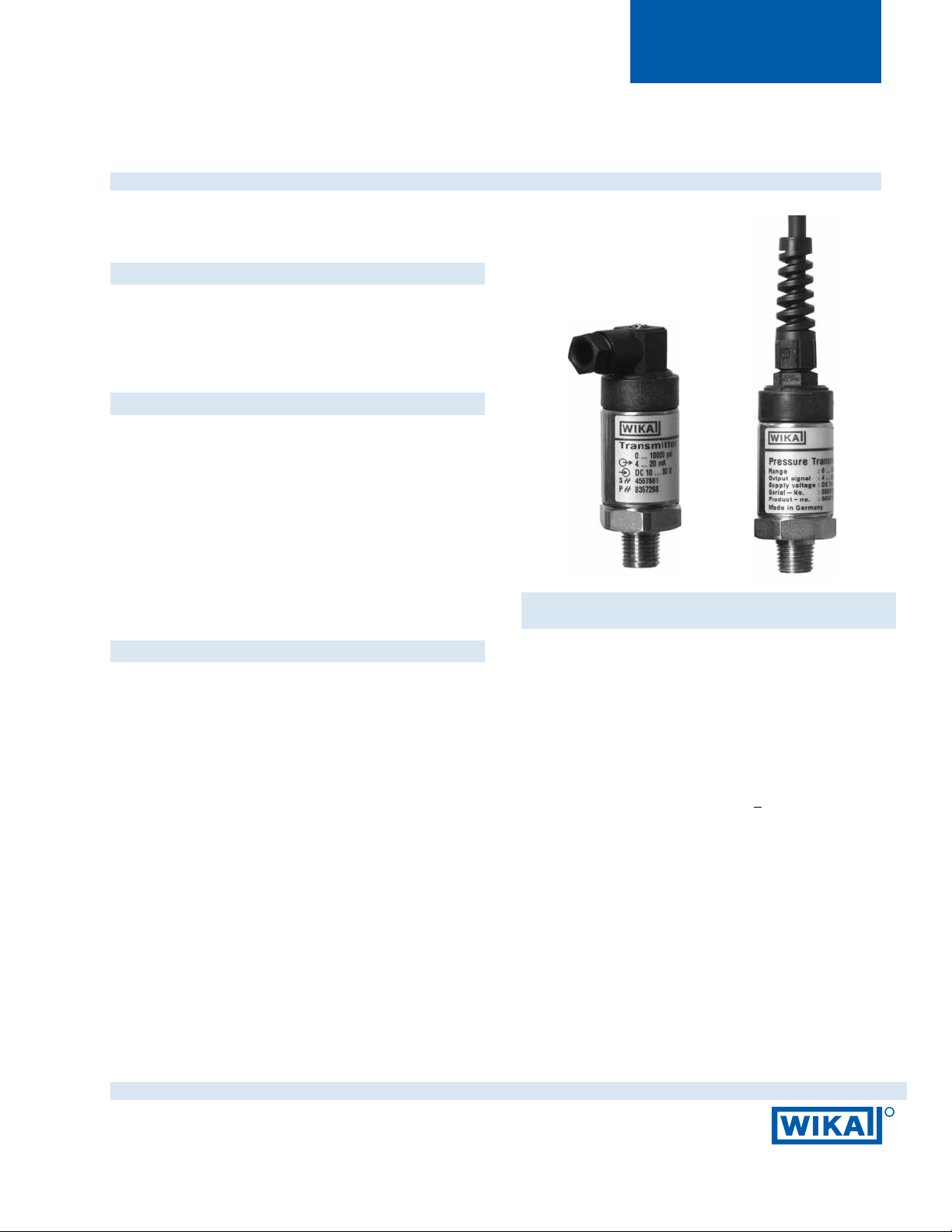
Left: C-10 with MiniDIN connector
Right: C-10 with optional cable
A standard signal output of 4-20 mA allows the C-10 to be
integrated into many existing applications. Many custom
signal outputs, process connections and electrical
connections are available.
Each C-10 undergoes extensive quality control testing and
calibration to achieve an accuracy of < 0.50% full scale. The
printed circuit boards use state-of-the-art surface mount
technology. Each is individually temperature compensated to
assure accuracy and long-term stability even when exposed to
severe ambient temperature variations.
WIKA Datasheet C-10 · 12/2010
Page 1 of 4
R
Page 2
Specications Model C-10
Pressure range 100 InWC 5 psi 10 psi 15 psi 25 psi 30 psi 50 psi 100 psi 200 psi
Maximum pressure* 29 psi 29 psi 58 psi 72 psi 145 psi 145 psi 240 psi 500 psi 1,160 psi
Burst pressure** 34 psi 34 psi 69 psi 87 psi 170 psi 170 psi 290 psi 600 psi 1,390 psi
Pressure range 300 psi 500 psi 1,000 psi 2,000 psi 3,000 psi 5,000 psi 7,500 psi 10,000 psi 15,000 psi
Maximum pressure* 1,160 psi 1,160 psi 1,740 psi 4,600 psi 7,200 psi 11,600 psi 17,400 psi 17,400 psi 21,750 psi
Burst pressure** 1,390 psi 5,800 psi 7,970 psi 14,500 psi 17,400 psi 24,650 psi 34,800 psi 34,800 psi 43,500 psi
{absolute pressure references are available}
*Pressure applied up to the maximum rating will cause no permanent change in specications but may lead to zero and span shifts
**Exceeding the burst pressure may result in destruction of the transmitter and possible loss of media
Materials
n Wetted parts
n Case
Stainless steel
Stainless steel
Internal transmission uid Synthetic oil, only for pressure ranges up to 0 ... 300 psi
Supply Voltage U
B
DC V 10 < UB ≤ 30 (14 ... 30 with signal output 0 ... 10 V)
Response time (10 ... 90 %) ms
Accuracy
2)
% of span ≤ 1.0 (limit point calibration)
®
{Halocarbon
oil for oxygen applications}
< 1 (< 10 ms at medium temperatures below -22°F (-30°C) for pressure ranges up to 300 psi
1)}
% of span ≤ 0.5 (BFSL)
esis % of span ≤ 0.1
Hyster
Non-repeatability % of span ≤
1-year stability % of span ≤ 0.2
0.05
(at re
ference conditions)
Permissible temperature of
n Medium
n Ambient
n Storage
-22 ... +212 °F -30 ... +100 °C
-22 ... +185 °F -30 ... +85 °C
-40 ... +212 °F -40 ... +100 °C
Compensated temperature range 0 ... +176 °F 0 ... +80 °C
Temperature coecients in
compensated temp range
n Mean TC of zero
n Mean TC of range
% of span ≤ 0.3 / 10 K
% of span ≤ 0.2 / 10 K
CE-conformity 89/336/EWG interference emission and immunity see EN 61326
97/23/EG Pressure equipment directive
Shock resistance g 1,000 according to IEC 60068-2-27 (mechanical shock)
Vibration resistance g 20 according to IEC 60068-2-6
(vibration under r
esonance)
Wiring protection Protected against reverse polarity, overvoltage and short circuiting
Ingress protection Per IEC 60529 / EN 60529, see page 3
Weight lb Approx. .22
1) Media temperature for oxygen version: -4 ... +140 °F (-20 ... 60 °C).
Cannot be manufactured for absolute pressure ranges < 1 bar abs.
2) Including linearity, hysteresis and repeatability.
Limit point calibration in vertical mounting position with down pressure connection.
{ } Items in cur ved brackets are optional extras for additional price.
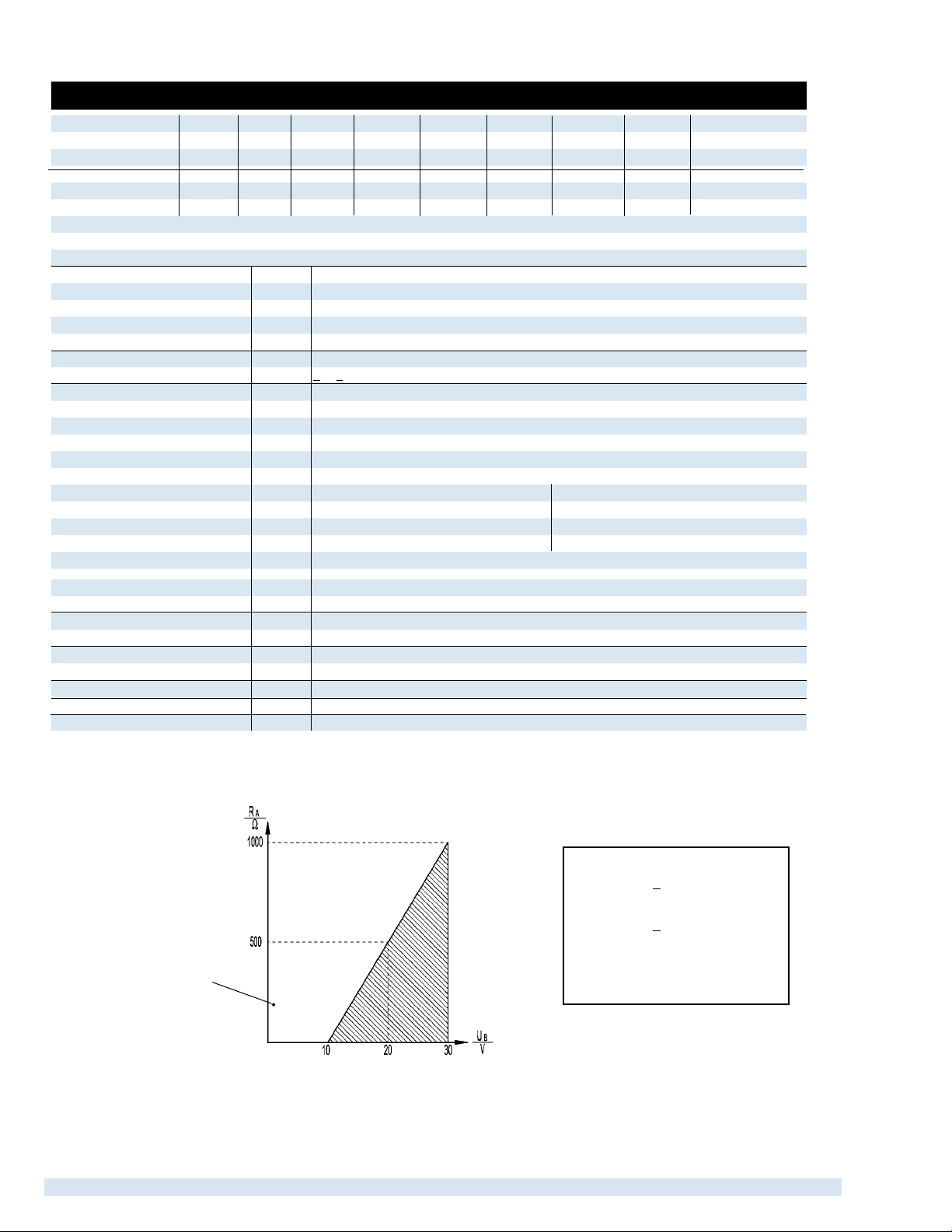
Output signal and
permissible load
permissible range
4 ... 20 mA, 2-wire
Output current (2-wire)
4 ... 20 mA: RA < (UB – 10 V) / 0.02 A
Output current (3-wire)
0 ... 20 mA: RA < (UB - 3 V) / 0.02 A
Output voltage (3-wire)
0 ... 5 V: RA >5 kOhm
0 ... 10 V: RA >10 kOhm
Supply
voltage
WIKA Datasheet C-10 · 12/2010Page 2 of 4
Page 3

Dimensions in inches (mm)
Electrical connections
Mini L-connector
G-series
IP 65
Order code: II
1.14“(29mm)
Case
Circular connector,
5-pin, M 12x1,
IP 65
Order code: M5
1.06“(27mm)
1.34“(34mm)
1.06“(27mm)
Cable with Free Ends
IP 65
Order code: CR
)
*
1.46“(37mm)
2.20“(56mm)
Pressure connections
1/4” NPT male
Order code: NB
.51“(13mm)
.85“(21.5mm)
) Mating connectors are not included
*
G 1/4 male
DIN 3852-E
Order code: HD
.55“(14mm)
.89“(22.5mm)
G 1/4 male
EN 837
Order code: GB
.51“(13mm)
.85“(21.5mm)
.08“(2mm)
.08“(2mm)
Other process connections available
Page 3 of 4WIKA Datasheet C-10 ·12/2010
Page 4

Wiring details
Mini L-connector
G-series
Circular connector
M 12x1 5 pin
Cable with 5 foot (1.5m)
of cable and free ends
Legend:
2-wire
Sig+ output signal positive
UB+ power supply positive
0V power supply negative
Sig - output signal negative
brown
green
3-wire
brown
white
green
Specications and dimensions given in this data sheet represent the state of engineering at the time of printing.
Modications may take place and materials specied may be replaced by others without prior notice.
WIKA Datasheet C-10 · 12/2010Page 4 of 4
R
WIKA Instrument Corporation
1000 Wiegand Boulevard
Lawrenceville, GA 30043
1-888-WIKA-USA /770-513-8200 (in GA)
Fax 770-338-5118
info@wika.com www.wika.com
 Loading...