

Page 1
Vision Assembly Guide 1
®
Vision
White’s Electronics, Inc. -
Manufacturers of the World’s Finest Metal Detectors
®
™
Guide to:
Assembly
Battery & Charger
Owner Registration
First-Time Out
Page 2

2 Vision Assembly Guide
Press ON/OFF.
Optionally… Press ZOOM to select text size.
Squeeze & release Trigger on the handle grip.
Hold Trigger & hold ENTER, pump search coil (loop) up
and down on the ground until background hum steadies, release
ENTER… and then release Trigger and begin searching.
(Note releasing Trigger before releasing ENTER) locks Vision
in pinpoint mode, squeeze and release trigger twice to unlock
pinpoint.
Sweep search coil close to the ground, from side to side,
overlapping each pass.
Locate a consistent “BEEP” upon several passes of the
search coil.
Look at display. VDI, Blocks, and ICON, indicate a metal
target worthy of digging.
Pinpoint squeeze & hold toggle on the grip and slowly “X”
the area. Depth in inches and maximum bars indicates target
center.
Vision
™
First Time Out - ”Turn On And Go” ...
Page 3
Vision Assembly Guide 3
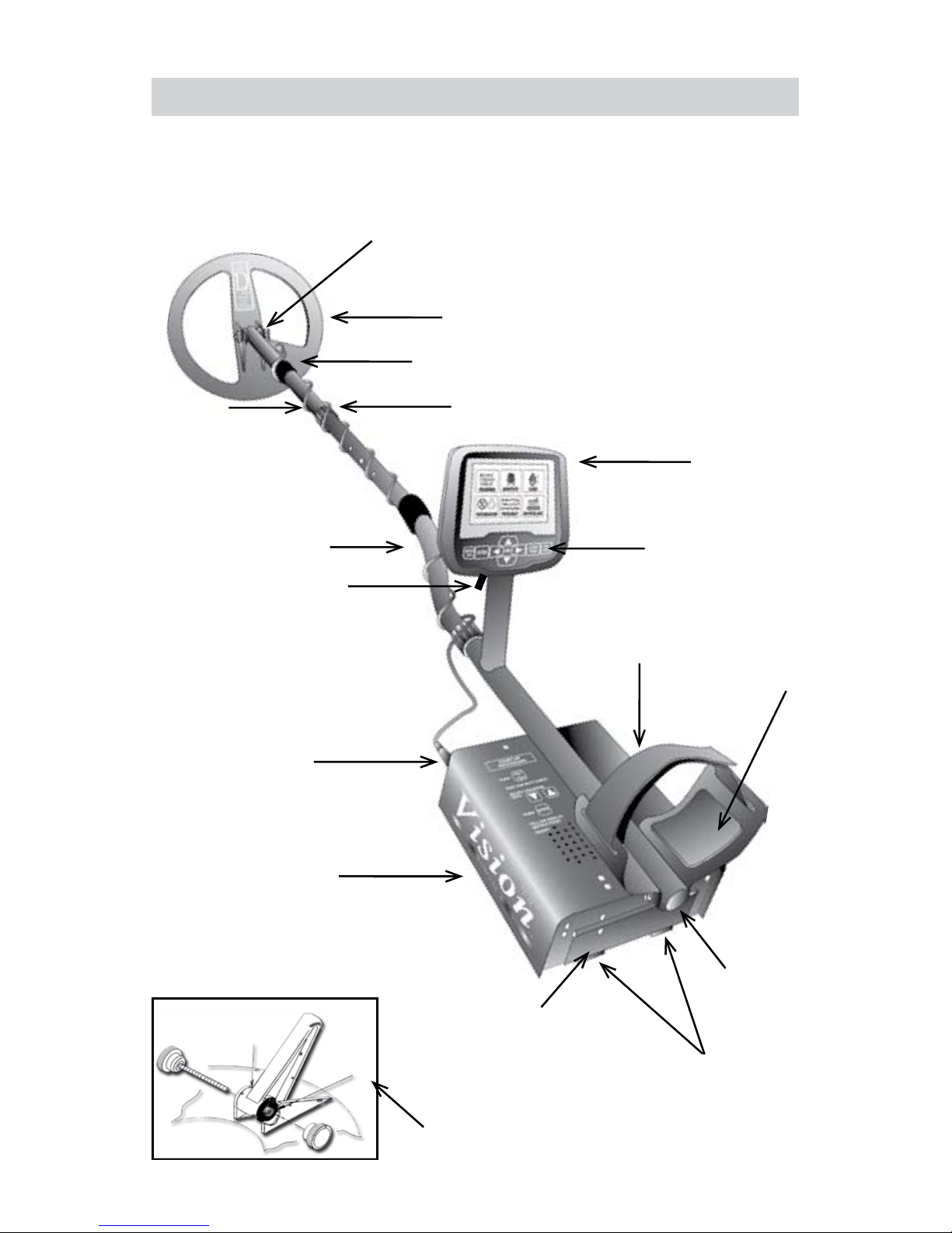
ASSEMBLY -
Washers between each
loop ear & clevis
Search Coil
Cable Retainer
Camlock
Battery
Compartment Door
Headphone
Jack
Battery
Compartment Latches
Clevis
Lower Rod
S-rod
Loop Connector
Control Box
Display
Touch Pads
Select Programs
Adjust Controls
Elbow Cup Strap
Elbow Cup Foam
Pads - Inside
Elbow Cup
Place soft rubber washer (b)
between clevis and ears - both sides.
b
b
Trigger
Page 4

4 Vision Assembly Guide
ASSEMBLY INSTRUCTIONS -
1. Remove all parts from shipping carton. Check the assembly page to make
sure all parts are present.
2. Use the provided rubber washers between clevis/lower rod and loop ears.
Use only nonmetallic washers, fiber bolt, and thumbnut to secure loop/search coil
to clevis/lower rod.
3. Unlock “S” rod camlock and insert clevis/lower rod into curved “S” rod
so that stainless steel spring clip buttons line up and lock into one of the
adjustment holes in the curved “S” rod. Turn camlock to secure. The second
or third adjustment holes are suitable for average size adults. Individuals 6’
or taller should use the fully extended position. Individuals well over 6’ tall
should purchase the optional Tall Man Fiber Lower Rod #500-0242-3 and/or
#500-0240-1 Tall Man Aluminum “S” Rod.
4. Unravel loop cable and wind the cable around the clevis and rod assembly,
first revolution over the top of the rod. Wind cable all the way to the top of the
curved “S” rod, about five revolutions. Use the black cable retainers, one near
the loop, and one near the top of the curved “S” rod, to hold the loop cable in
place.
5. Unlock control box rod cam-lock and insert curved “S” rod so that stainless
steel spring clip buttons line up and lock into the rod on top of the control box.
The “S” rod is designed to curve up toward the display. However, those who
prefer to sweep the loop close to their feet may desire to assemble the “S” rod
to curve down toward the ground. Turn cam-lock to secure. Plug loop connector
into control box, screw lock ring to secure.
6. Grip the instrument by the handle, with your arm in the elbow cup with strap
secure, and sweep the loop/search coil over the floor. If the instrument fit feels
uncomfortable, adjust the elbow cup by removing and repositioning the bolt/
thumbnut and installing in one of the optional positions. If necessary, readjust
clevis/lower rod length with the spring clip buttons and cam-lock so that the
search coil can be held near the floor without requiring stooping over.
Page 5
Vision Assembly Guide 5
7. Remove the protective paper from the two black elbow cup foam pads.
Carefully align pads on the inside of the elbow cup, one on each side of the
center rod, and press firmly into place.
8. Adjust the elbow cup strap so that it is loose enough for you to slide your arm
in and out without loosening each time you want to set the detector down. The
elbow cup strap provides extra leverage and control. However, some prefer not
to use it.
9. Install battery as described in the next section, decal facing down, single
larger plastic tab and steel contacts facing toward inside of battery compartment.
10. It should be noted at this point that the Vision may not work as expected
indoors due to the high degree of metals used in modern construction. It is best
to tune and practice (outdoors) to ensure stable, predictable results.
11. Your Vision is designed with an automatic turn OFF if the trigger on the grip
(or another control) “is not used” for a period of 30 minutes. This protects the
battery from damage (absolute discharge) in case of an accidental turn on during
travel or storage. The Vision will make a specific deep tone musical melody
upon automatic turn off. To restart, simply press ON and squeeze and release
the trigger on the grip to resume searching. The Vision returns to pre-turn-off
settings.
Batteries
The Vision is provided with two battery packs. A rechargeable Nickel Metal
Hydride (NiMH) battery (Orange Decal) will require an initial 3-4 hour battery
charge.
Orange Decal
Page 6

6 Vision Assembly Guide
To begin using the Vision immediately, use the back-up “AA” battery pack (Blue
Decal).
• The standard battery holder (Blue Decal) holds eight “AA” cell
batteries. Alkaline batteries are recommended for use with this battery holder.
• Non-alkaline batteries can be used in this holder. When non-alkaline
or rechargeable “AA” cells are used, detecting time (before replacement/
recharge) may be reduced or increased depending upon the type of battery
used.
• An ” Unhappy Battery Icon” will automatically appear on the
display (lower left status line) when the batteries become too low (8 volts) to
properly operate the Vision.
• A headphone icon with a battery inside indicates the batteries are low
in the wireless headphone. See additional status indications on bottom of control
box.
• The battery compartment opens by gently pulling down on the front
of each of the two latches (on the bottom of the control box) releasing the catch
and hinging open the door. The non-rechargeable battery holder can use many
different types of batteries, including rechargeable. This holder is designed for
standard size “AA” batteries 50 mm ± .10 mm. Battery lengths shorter than this
will likely cause problems with this power supply.
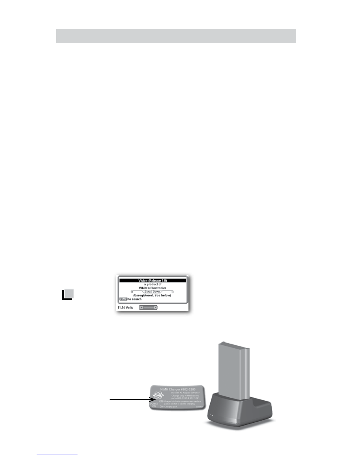
• When the Vision is turned on the battery voltage will momentarily
appear on the opening display (lower left). The degree the battery is filled, toward
+, indicates the battery condition. Full Fill = 100% battery life remaining, half fill =
50% battery life remaining.
• To recheck the battery voltage during searching, press MENU twice
and note battery voltage under BATTERY. Vision operates correctly between 8
Volts “low battery” and 13 Volts. Squeeze and release Trigger on grip (twice) to
Blue Decal
Battery Voltage Reading
Page 7

Vision Assembly Guide 7
return to searching. Initial battery check voltage may indicate abnormally high.
With new Alkaline, or a fresh battery charge, the most accurate battery voltage
will be indicated after one hour of use.
Using the Standard Battery Holder
• Slide open the battery holder lid (decal side of battery holder) by applying
gentle upward pressure on the single large tab of the door so that it unlocks.
Slide the door away from the battery box exposing the cell positions.
• Remove any old cells from the holder. Note the “+” and “-“ positions of
each cell and the “+” and “-“ for each position marked inside the cell tray. Install
new “AA” cells noting carefully the correct (+) and (-) positions. If any of the cells
are installed incorrectly, battery life will be significantly reduced and/or the Vision
may require service by an Authorized Service Center.
• Slide the door closed so that it snaps securely.
• Insert the battery holder into the detector so that the decal is
facing down, with the single larger battery holder door tab and metal contact
points facing toward the inside of the battery compartment. Close the battery
compartment door and secure the two latches on the bottom of the case. Hook
the front (nearest the door) of each latch first, and then snap down the rear
(furthest from the door).
Page 8

8 Vision Assembly Guide
NiMH Rechargeable Battery
• A rechargeable NiMH (Nickel Metal Hydride) battery (Orange Decal)
is provided with your Vision. This battery can be recharged hundreds of times.
Full charge can be achieved anytime during the discharge cycle (a non-memory
system). The provided “Smart Charger” and “Charging Cradle/Stand” sense
the type of charge the battery needs and automatically adjust the charge cycle.
From fully low this system provides a full charge in as little as 3-4 hours. A full
charge will last ten to twelve hours of normal use. Battery life will vary with
temperature, the number of targets found, and the exact settings used. Six hours
is not unusual for extreme high performance settings, or for batteries that have
experienced extensive use.
• The battery will lose its charge during storage. If stored inserted in
your instrument, this loss will be more significant. It is recommended that the
battery be removed from the Vision during periods of storage. It is not advisable
to store rechargeable batteries for long periods of time without use (six +
months). If extended storage is necessary, store with a charge (charged). If
possible, recharge at least once every six months of non-use.
• Do not discharge the battery in devices other than your metal
detector. Unnecessary discharging and/or an absolute discharge will reduce
battery life and may damage the battery. Unlike older rechargeable battery
designs, the rechargeable battery provided with your Vision can be recharged at
any time. Regardless of whether or not it already has a partial charge, memory
will not occur.
• White’s has provided the leading edge NiMH rechargeable battery
technology with your Vision. Disregard advice that conflicts with the above
recommendations. Care for batteries provided by other manufacturers, or with
other White’s models, may vary.
• Do not combine (use) any other battery, or any other battery charger,
not specifically designed to work with this system.
• The NiMH battery provided with your Vision may be subject to
recycling laws in your area. It is the right thing to do and is often legally required.
If, perhaps many years in the future, you are uncertain as to where to return a
Page 9

Vision Assembly Guide 9
White’s NiMH batteries for recycling, please return it to the place of purchase or
any White’s Electronics Inc. address circling “the recycling” (trash can) portion of
the label.
• Charging
- Plug the charger into a standard wall outlet. (110 volts for USA
models, 220 volts for UK models).
- To charge, insert the battery into the cradle / stand (only fits one way)
plug the charger plug into the back of the cradle / stand. Green light should glow.
- Green and Red Lights ON indicate battery and charger have made
a good connection and the battery is charging. The battery charger is designed
to charge a completely low battery in as little as 3-4 hours. However, no harm
will come to the system leaving it charging for several days (automatic trickle
charge).
- Red Light OFF, Green Light ON indicates battery is now fully charged
and ready for use and will now simply maintain the full charge indefinitely. It is
normal for the battery and charger to get warm during use. However, if either
the battery or the charger gets too hot to hold or deforms due to the heat,
discontinue use and return for testing.
- When using fresh batteries, the voltage will initially check somewhere
in the 10 to 13 volt area. Unlike standard batteries, the rechargeable battery
voltage will quickly drop somewhere between 9 and 11 volts and plateau there
for most of its life. Once the rechargeable battery voltage drops below this
plateau, it will quickly drop below a usable voltage level (8 volts) and thus require
a recharge. “Unhappy Battery Icon” will automatically appear on the display when
the battery approaches 8 volts. It is recommended to either recharge or switch
to “AA” pack when occasional unhappy battery starts to appear (flash) on display.
With a consistent unhappy battery, Vision will not be operating properly and will
soon entirely cease to operate.
Page 10

10 Vision Assembly Guide
Owner Registration
How to Access – To access Information / Configure press MENU twice in
succession. Arrow down to Owner Registration and press ENTER. To Exit
squeeze and release trigger on hand grip twice
Owner Registration – Allows the Vision owner to embed their name and contact
information, protected from tampering, but updateable with original factory code.
• Select Owner Register and press ENTER. Press MENU / TAB to select
Register and press ENTER.
• Password – IMPORTANT! Write down the password or code that
automatically appears and keep it in a safe place separate from your Vision…
(Password code will disappear, and must be manual re-entered, after first
registration). If you normally keep your instruction manual at home, write it
on the inside cover of the manual. Should you ever change addresses or sell
your vision, this code must be retained and manually re-entered to update or
revise your Visions registration information. To detour theft, without this original
disappearing code, significant inconvenience can be expected regarding resetting the Registration information.
Owner’s Name – Use the ARROWs Down / Up, and Left / Right to spell out your
name. Or press ENTER to bring up a key-board and then use ARROWs and
ENTER to spell out your name.
• Select and ENTER blanks to add spaces. If you make an error, to redo
that digit, squeeze and release trigger, ARROW back to that digit, and press
ENTER to bring the Keyboard back, then redo that digit.
Page 11

Vision Assembly Guide 11
Contact - Press MENU / TAB to exit Name and select Contact. Type out your
contact information using ARROWs, or pressing Menu to bring up the keyboard
then ARROWs and ENTER.
SAVE – Use MENU / TAB to select SAVE, press ENTER to SAVE your
Registration.
Page 12

12 Vision Assembly Guide
USA / Australian Service Centers
1. White’s Electronics
1011 Pleasant Valley Rd.
Sweet Home, OR 97386
(541) 367 6121
Fax (541) 367 6629
Tmarshall@whiteselectronics.com
3. Centreville Electronics
10063 Wellington Rd.
Manassas, Va. 20110
(888) 645-0202
(703) 367-7999
(703) 367-0868 FAX
bob@cwrelics.com
2. Electronic
Exploration
575 West Harrison
Lombard, IL 60148
(800) 392-3223
(630) 620-0618
(630) 620-1005 FAX
Gold Search Australia
Tony Mills Distributor
76 Broadway, Dunolly Vic 3472
Telephone: (+61) 03 5468 1877
Fax: (+61) 03 5468 1667
info@goldsearchaustralia.com
www.goldsearchaustralia.com
Australia -
Page 13

Vision Assembly Guide 13
White’s reputation has been built on quality products backed by quality service.
Our Factory Authorized Service Centers are factory trained and equipped. They
offer the same quality service as the factory. Service before and after the sale is
the cornerstone of our customer relations.
a. Contact your Dealer. There may be a quick, simple fix or explanation
that will prevent having to send the detector in for service.
b. Double check the obvious, such as batteries, and try the detector in
another area to be sure there isn’t interference.
c. Be sure to send all necessary parts with your detector, such as
batteries and holders, as these items can result in symptoms.
Before shipping detectors for service -
• Always include a letter of explanation about your concerns, even if
you have talked to the Service Center by telephone.
• Take care in packaging instruments for shipping. Always insure your
package.
(USA) Warranty
If within two years (24 months) from the original date of purchase, your White’s
detector fails due to defects in either material or workmanship, White’s will repair
or replace at its option, all necessary parts without charge for parts or labor.
Simply return the complete detector to the Dealer where you purchased it, or to
your nearest Authorized Service Center.
The unit must be accompanied by a detailed explanation of the symptoms of the
failure. You must provide proof of date-of-purchase before the unit is serviced.
This is a transferable manufacturer warranty, which covers the instrument two
years from the original purchase date, regardless of the owner.
Items excluded from the warranty are non-rechargeable batteries, accessories
that are not standard equipment, shipping/handling costs outside the continental
USA, Special Delivery costs (Air Freight, Next Day, 2nd Day, Packaging
Services, etc.) and all shipping/handling costs inside the continental USA 90
days after purchase.
Page 14

14 Vision Assembly Guide
White’s registers your purchase only if the Sales Registration Card is filled out
and returned to the factory address soon after original purchase for the purpose
of recording this information, and keeping you up-to-date regarding White’s
ongoing research & development.
The warranty does not cover damage caused by accident, misuse, neglect,
alterations, modifications, unauthorized service, or prolonged exposure to
corrosive compounds, including salt.
Duration of any implied warranty (e.g., merchantability and fitness for a particular
purpose) shall not be longer than the stated warranty. The manufacturer nor
the retailer shall be liable for any incidental or consequential damages. Some
states however, do not allow the limitation on the length of implied warranties,
or the exclusion of incidental or consequential damages. Therefore, the above
limitations may not apply to you.
In addition, the stated warranty gives you specific legal rights, and you may have
other rights, which vary from state-to-state.
The foregoing is the only warranty provided by White’s as the manufacturer of
your metal detector.
Any “extended warranty” period beyond two years, which may be provided by
a Dealer or other third party on your detector, may be without White’s authority,
involvement and consent, and might not be honored by White’s.
USA Warranty Transfer
If for any reason you should sell your Vision prior to the date the warrant
expires, the remaining warranty is transferable. Call 1-800-547-6911, and get an
Authorization Number to authorize this transfer.
Page 15

Vision Assembly Guide 15
• Help Balloons - From menu screens and Zoom menus, trigger forward - brings up a
“Help Balloon” that offers more information about the menu item.
Trigger Forward
Help Balloon
First Aid
• COMPLETE OWNER’S GUIDE - All of Vision’s systems and controls are explained in
complete detail.
• DVD - A short DVD designed to visually familiarize and instruct.
• Website/Forum - Ask questions, comment and share your experiences with
White’s Vision owners at White’s Website Forum: www.whiteselectronics.com.
• Live Help - Consult your local Dealer or contact White’s Authorized Regional
Distributor at 1-800-547-6911. We will be happy to help!
NOTE -
Explore your Vision metal detector with complete confidence.
You cannot harm or destroy the original factory presets or software.
Original programs are easily restored!
FROM
Use to select program. Use to highlight RESTORE.
Selected program displays checkmark and is restored to factory settings.
• Wireless Headphone “enable on/off setting is NOT changed by “Restore”.
• Removing battery does NOT restore factory programs.
Press
TO RESTORE FACTORY PROGRAMS
to RESTORE - Press
Page 16

16 Vision Assembly Guide
Press ON/OFF.
Optionally… Press ZOOM to select text size.
Squeeze & release Trigger on the handle grip.
Hold Trigger & hold ENTER, pump search coil (loop) up
and down on the ground until background hum steadies, release
ENTER… and then release Trigger and begin searching.
(Note releasing Trigger before releasing ENTER) locks Vision
in pinpoint mode, squeeze and release trigger twice to unlock
pinpoint.
Sweep search coil close to the ground, from side to side,
overlapping each pass.
Locate a consistent “BEEP” upon several passes of the
search coil.
Look at display. VDI, Blocks, and ICON, indicate a metal
target worthy of digging.
Pinpoint squeeze & hold toggle on the grip and slowly “X”
the area. Depth in inches and maximum bars indicates target
center.
Vision
™
- White’s Vision Metal Detectors Manufactured in
Sweet Home, Oregon USA
First Time Out - ”Turn On And Go” ...
P/N 621-0514 Printed in USA 3/09
 Loading...