


XLT® Table of Contents
Contents |
Page |
||
Assembly .......................................................................................................................................................................................... |
|
|
2 |
Batteries ........................................................................................................................................................................................... |
|
|
4 |
XLT® Quick Start ........................................................................................................................................................................... |
8 |
||
Basic Adjustments ........................................................................................................................................................................ |
14 |
||
1. |
Target Volume .............................................................................................................................................................. |
18 |
|
2. Audio Threshold ........................................................................................................................................................... |
18 |
||
3. |
Tone (Audio Frequency) .............................................................................................................................................. |
19 |
|
4. Audio Disc. ................................................................................................................................................................... |
19 |
||
5. |
Silent Search ................................................................................................................................................................ |
20 |
|
6. Mixed Mode ................................................................................................................................................................. |
21 |
||
7. A.C. Sensitivity ............................................................................................................................................................ |
22 |
||
8. |
D.C. Sensitivity ............................................................................................................................................................ |
22 |
|
9. |
Backlight ...................................................................................................................................................................... |
23 |
|
10. Viewing Angle ............................................................................................................................................................ |
24 |
||
Pro Options ................................................................................................................................................................................... |
25 |
||
Audio ......................................................................................................................................................................................... |
|
|
27 |
1. |
Ratchet Pinpointing ...................................................................................................................................................... |
27 |
|
2. |
S.A.T. Speed ................................................................................................................................................................. |
28 |
|
3. |
Tone I.D. ....................................................................................................................................................................... |
29 |
|
4. V.C.O. ........................................................................................................................................................................... |
29 |
||
5. Absolute Value ............................................................................................................................................................. |
30 |
||
6. |
Modulation ................................................................................................................................................................... |
30 |
|
G.E.B./Trac ............................................................................................................................................................................... |
30 |
||
7. AutoTrac® ................................................................................................................... ................................................. |
31 |
||
8. Trac View ..................................................................................................................................................................... |
31 |
||
9. |
Trac Speed .................................................................................................................................................................... |
32 |
|
10. |
Trac Offset .................................................................................................................................................................. |
33 |
|
11. Trac Inhibit ................................................................................................................................................................. |
33 |
||
12. |
Coarse G.E.B. ............................................................................................................................................................. |
34 |
|
13. |
Fine G.E.B. ................................................................................................................................................................. |
35 |
|
Discrimination .......................................................................................................................................................................... |
36 |
||
14. |
Disc. Edit .................................................................................................................................................................... |
36 |
|
15. |
Block Edit .................................................................................................................................................................. |
38 |
|
16-17. Learn Accept/Reject .............................................................................................................................................. |
39 |
||
18. |
Recovery Speed .......................................................................................................................................................... |
40 |
|
19. |
Bottlecap Reject ......................................................................................................................................................... |
41 |
|
Display ....................................................................................................................................................................................... |
|
|
42 |
20. |
Visual Disc. ................................................................................................................................................................ |
42 |
|
21. |
Icons ........................................................................................................................................................................... |
42 |
|
22. |
V.D.I. Sensitivity ........................................................................................................................................................ |
43 |
|
23. |
D.C. Phase .................................................................................................................................................................. |
44 |
|
24. Accumulate ................................................................................................................................................................. |
45 |
||
25. Average ....................................................................................................................................................................... |
45 |
||
26. |
Fade ............................................................................................................................................................................ |
46 |
|
Signal ......................................................................................................................................................................................... |
|
|
47 |
27. Transmit Boost ........................................................................................................................................................... |
47 |
||
28. |
Transmit Frequency .................................................................................................................................................... |
48 |
|
29. |
Preamp Gain ............................................................................................................................................................... |
49 |
|
Program Settings Chart ............................................................................................................................................................... |
50 |
||
Glossary ......................................................................................................................................................................................... |
|
|
52 |
Warranty ....................................................................................................................................................................................... |
|
|
53 |
1

Chapter 1 XLT® Assembly
Assembly
WASHERS |
|
|
BETWEEN |
|
|
EACH LOOP |
LOOP OR SEARCH |
|
EAR & CLEVIS |
||
COIL |
||
|
||
|
CABLE RETAINERS |
CENTER ROD
SECTION
CLEVIS LOWER
ROD  LOOP
LOOP
CABLE
CAMLOCKS
“S” ROD
Twist and insert each end of handle (provided) through top of shipping carton into second flap.
(CARRY CARTON)
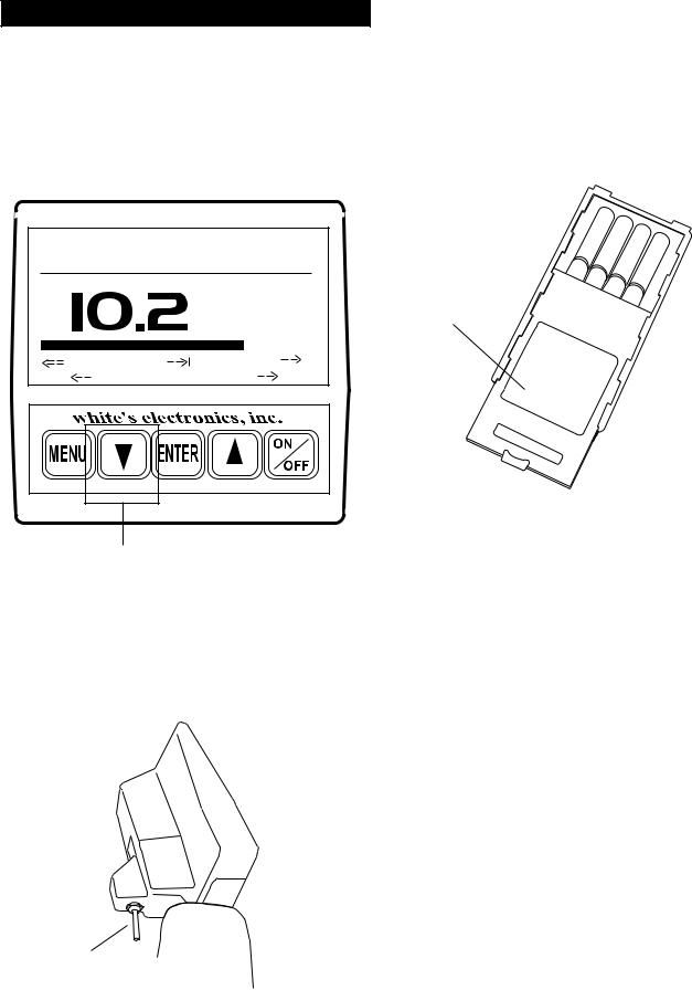
DISPLAY
1/ PRESET PROGRAMS 2/ BASIC ADJUSTMENTS 3/ PRO OPTIONS
4/ TARGET ID NUMBERS 5/ TARGET ID ICONS
6/ TARGET ID SIGNAGRAPH® 7/ BATTERY STRENGTH
TOUCH PADS
SELECT PROGRAMS
ADJUST CONTROLS
Trigger behind display activates LOOP CONNECTOR depth reading and
pinpoint mode.
Remove decal paper from the two rubber bumpers. Install on the bottom of the control box, one in each of the front corners (shown below by "X"). Press in place and hold firmly for a few seconds then release.
|
"X" |
|
|
|
|
|
|
|
|
"X" |
|
||
|
|
|
|
|
|
|
|
|
|||||
|
|
"HOT KEY" SHORTCUTS |
|
|
|||||||||
|
|
|
|
|
|
|
|
|
|
|
|||
|
COIN PROGRAM |
|
REVERSE DISPLAY |
|
|||||||||
|
SQUEEZE & RELEASE TRIGGER |
WHILE SEARCHING. HOLD |
|
||||||||||
|
AFTER BATT. CHECK. |
|
THE TRIGGER AND PRESS |
|
|||||||||
|
SCROLL OPTIONS |
|
PRESS |
FOR |
|
||||||||
|
ATER BATT. CHECK USE |
|
|||||||||||
|
TO SCROLL CURRENT SETTINGS |
LIGHT/DARK BACKGROUND. |
|
||||||||||
|
OR MAKE ADJUSTMENTS |
RELEASE TRIGGER |
|
||||||||||
|
AIR/GND BALANCE |
|
BACKLIGHT |
|
|
|
|
|
|||||
|
IN SEARCH MODE PRESS |
IN SEARCH MODE, HOLD THE |
|
||||||||||
|
TO RE-AIR/GND BALANCE |
TRIGGER AND PRESS |
|
||||||||||
|
|
|
|
|
|
|
RELEASE TRIGGER |
|
|||||
|
|
|
|
|
|
|
PUSH |
|
|
|
|
|
|
|
GROUND BALANCE ONLY |
VIEW ANGLE |
|
|
|
|
|
||||||
|
WHILE SEARCHING HOLD THE |
WHILE SEARCHING HOLD |
|
||||||||||
|
TRIGGER AND PRESS |
|
THE TRIGGER AND PRESS |
|
|||||||||
|
|
|
|
|
|
|
RELEASE TRIGGER |
|
|||||
|
BATTERY CHECK |
|
PUSH |
|
|
|
|
|
|||||
|
WHILE SEARCHING, HOLD THE |
|
|
|
|
|
|
|
|||||
|
TRIGGER AND PRESS |
|
|
|
|
|
|
|
|
||||
|
|
|
|
|
|
|
|
|
|
|
|
|
|
|
|
|
|
|
|
|
|
|
|
|
|
|
|
|
|
|
|
|
|
|
|
|
|
|
|
|
|
BOTTOM OF
CONTROL BOX
CONTROL BOX
ELBOW
|
|
|
CUP |
ELBOW CUP |
|
|
|
FOAM PADS |
|
|
|
|
STRAP |
|
|
|
|
INSIDE ELBOW |
|
|
|
|
|
|
|
|
|
|
CUP |
|
|
|
|
|
|
|
|
|
|
|
|
|
|
|
|
|
|
|
|
|
|
|
|
|
|
|
|
|
|
HEADPHONE
JACK
BATTERY BATTERY COMPARTMENT COMPARTMENT LATCHES DOOR
2

Assembly Instructions
1.Remove all parts from shipping carton and check the assembly page to make sure all parts are present.
2.There are rubber washers between clevis/lower rod and loop ears. Use only nonmetallic washers, fiber bolt, and thumbnut to secure loop/search coil to clevis/lower rod.
3.Unlock "S" rod camlock and insert clevis/ lower rod into curved "S" rod so that stainless steel spring clip buttons line up and lock into one of the adjustment holes in the curved "S" rod. Turn camlock to secure. The second or third adjustment holes are suitable for average size adults. Individuals 6' or taller should use the fully extended position. Individuals well over 6' tall should purchase the optional Tall Man Rod.
4.Unravel loop cable and wind the cable around the clevis and rod assembly, first revolution over the top of the rod. Wind cable all the way to the top of the curved "S" rod, about five revolutions. Use the black cable retainers, one near the loop, and one near the top of the curved "S" rod, to hold the loop cable in place.
5.Unlock control box rod camlock and insert curved "S" rod so that stainless steel spring clip buttons line up and lock into the rod on top of the control box. The "S" rod is designed to curve up toward the display. However, those who prefer to sweep the loop close to their feet may desire to assemble the "S" rod to curve down toward the ground. Turn camlock to secure. Plug loop connector into control box, screw lock ring to secure.
6.Grip the instrument by the handle, with your arm in the elbow cup with strap secure, and sweep the loop/ search coil over the floor. If the instrument fit feels uncomfortable, adjust the elbow cup by removing
and repositioning the bolt/thumbnut and installing in one of the optional positions. If necessary,
Chapter 1 XLT® Assembly
readjust clevis/lower rod length with the sping clip buttons so that the search coil can be held near the floor without requiring stooping over.
7.Remove the protective paper from the two black elbow cup foam pads. Carefully align pads on the inside of the elbow cup, one on each side of the center rod, and press firmly into place.
8.Adjust the elbow cup strap so that it is loose enough for you to slide your arm in and out without loosening each time you want to set the detector down. The elbow cup strap provides extra leverage and control. However, some prefer not to use it.
9.Install battery as described in the next section, decal facing down, with plastic tab and steel contacts facing toward inside of battery compartment.
10.It should be noted at this point that the detector may not work as expected indoors due to the high degree of metals used in modern construction. It is best to tune and practice out-of-doors to ensure stable, predictable results. Additionally, freshlyburied targets will not produce the normal depth and discrimination results of targets that have been naturally lost and settled in the ground. Due to the abnormality caused by digging a hole in the ground matrix, and the sophistication of the ground rejection circuitry, it may take a number of years for freshly-buried targets to respond at true depths and discrimination accuracy. The best way to determine true detection depth is in real search conditions.
3
Chapter 2 XLT® Batteries
Batteries
Standard Battery Holder
BATTERY CHECK
VOLTS
|
NICAD |
ALK |
6 LOW |
OK |
14.0 |
ARROW DOWN
When the instrument is turned on the battery voltage will momentarily appear after the opening display. The detector will then continue to the MAIN MENU. To recheck the battery voltage during operation, squeeze and hold the TRIGGER and press the ARROW DOWN control.
TRIGGER
UNDER
DISPLAY POD
BLUE DECAL
Battery |
CAUTION |
|
|
Holder |
#802- |
|
|
7150 |
LIFT |
TAB |
AND |
|
|
|
||
|
|
PULL |
|
|
|
|
1.The standard battery holder (blue decal) holds eight “AA” cell batteries. Alkalines are recommended for use with this model.
2.Non-alkaline batteries can be used in this holder. When non-alkalines or rechargeable “AA”
cells are used, detecting time (before replacement/ recharge) may be reduced.
3."LOW BAT" will automatically appear on the display when the batteries become too low to properly operate the detector.
4.The battery compartment opens by gently pulling down on the front of each of the two latches (on the bottom of the control box) releasing the catch and hinging open the door.
The non-rechargeable battery holder can use many different types of batteries, including rechargeable. This holder is designed for standard size penlight "AA" batteries which should be 50 mm ± .10mm. Battery lengths shorter than this will likely cause problems with this power supply.
4
Using the
Standard Battery Holder
1.Slide open the battery holder lid (decal side of battery holder) by applying gentle upward pressure on the tab of the door so that it unlocks. Slide the door away from the battery box exposing the cell positions.
2.Remove any old cells from the holder. Note the
(+) and (-) positions of each cell and the (+)
and (-) for each position marked inside the cell tray. Install new “AA” cells noting carefully the correct (+) and (-) positions.
If the cells are installed incorrectly, the detector may require service by an Authorized
Service Center.
3.Slide the door closed so that it snaps securely.
4.Insert the battery holder into the detector so that the decal is facing down, with the battery
holder door tab and metal contact points facing toward the inside of the battery compartment.
Close the battery compartment door and secure the two latches on the bottom of the case. Hook the front of each latch first, then press down on the rear.
BATTERY
COMPARTMENT DOOR
BATTERY HOLDER
WITH DECAL SIDE DOWN AND
METAL CONTACTS TO FRONT
Chapter 2 XLT® Batteries
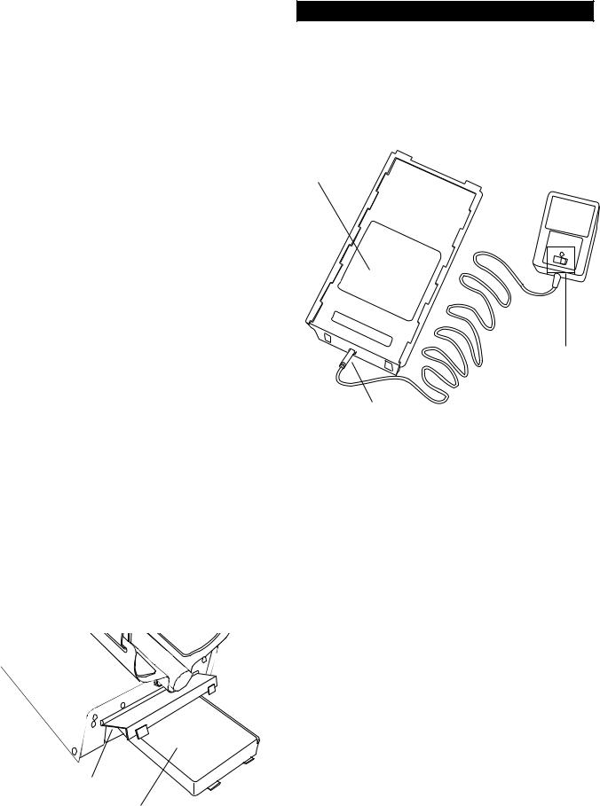
Rechargeable Battery
GREEN
DECAL BATTERY CHARGER
BatteryCAUTION
|
QUICK |
|
CHARGE |
|
OR OVER- |
|
NIGHT |
CHARGER PLUG |
SWITCH |
A rechargeable battery (green decal) is provided with your instrument. This battery can be recharged hundreds of times as long as the battery hasn't been stored for extended periods of time or overcharged. Full charge can be achieved anytime during the discharge cycle. When using the QUICK charger setting use the Charging Hours chart on the following page for charge time. A full charge will last ten to fifteen hours of normal use.
Battery life will vary with temperature, the number of targets found, and the exact settings used. Six hours is not unusual for extreme high performance settings, backlight use, or for batteries that have experienced extensive use.
Your charger has a switch on it that selects the QUICK charge, or OVERNIGHT charger options. Always check the position of this switch prior to charging. Always follow the charge hours on the chart on the following page when the QUICK charge setting is used. Over-charging with the QUICK charge setting will damage the system.
5
Chapter 2 XLT® Batteries
Charging
1. There is no harm charg- |
|
|
|
|
|
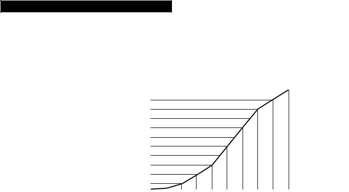
Using the Battery Charger on Quick Charge Setting |
|||||||||||||
|
5 |
|
|
|
|
|
|
|
|
|
|
|
|
|
|
|
|
|
|
|
|
|
|
|
|
|
|
|
|
|
|
|
|
|
|
|
|
||
ing overnight using the |
|
|
|
|
|
|
|
|
|
|
|
|
|
|
|
|
|
|
|
|
4.5 |
|
|
|
|
|
|
|
|
|
|
|
|
|
|
|
|
|
|
|
|
|
|
|
|
|
|
|
|
|
|
|
|
|
|
|
|
||
OVERNIGHT charger |
|
|
|
|
|
|
|
|
|
|
|
|
|
Any voltage reading |
|
||||
|
4 |
|
|
|
|
|
|
|
|
|
|
|
|
|
|||||
|
|
|
|
|
|
|
|
|
|
|
|
|
|
||||||
setting regardless of the |
|
|
|
|
|
|
|
|
|
|
|
|
|
less than 8 volts- |
|
||||
|
3.5 |
|
|
|
|
|
|
|
|
|
|
|
|
|
|||||
battery's current condition. |
|
|
|
|
|
|
|
|
|
|
|
|
|
charge for 5 hours |
|
||||
|
3 |
|
|
|
|
|
|
|
|
|
|
|
|
|
|||||
|
|
|
|
|
|
|
|
|
|
|
|
|
|
||||||
However, before charging |
Charging |
|
|
|
|
|
|
|
|
|
|
|
|
maximum on |
|
||||
2.5 |
|
|
|
|
|
|
|
|
|
|
|
|
Quick Charge |
|
|||||
with the QUICK charger |
Hours |
|
|
|
|
|
|
|
|
|
|
|
|
|
|||||
2 |
|
|
|
|
|
|
|
|
|
|
|
|
setting. Further |
|
|||||
|
|
|
|
|
|
|
|
|
|
|
|
|
|
||||||
setting, determine battery |
|
1.5 |
|
|
|
|
|
|
|
|
|
|
|
|
charging can |
|
|||
|
|
|
|
|
|
|
|
|
|
|
|
|
|
||||||
|
|
|
|
|
|
|
|
|
|
|
|
|
damage the |
|
|||||
condition by inserting |
|
1 |
|
|
|
|
|
|
|
|
|
|
|
|
|
||||
|
|
|
|
|
|
|
|
|
|
|
|
|
|
||||||
|
|
|
|
|
|
|
|
|
|
|
|
|
system. |
|
|||||
battery into the instrument |
|
0.5 |
|
|
|
|
|
|
|
|
|
|
|
|
|
||||
|
|
|
|
|
|
|
|
|
|
|
|
|
|
|
|
|
|
||
and turning the instrument |
|
0 |
|
|
|
|
|
|
|
|
|
|
|
|
|
|
|
|
|
|
|
|
|
|
|
|
|
|
|
|
|
|
|
|
|
|
|
||
|
|
|
|
|
|
|
|
|
|
|
|
|
|
|
|
|
|
||
ON. If the instrument will |
|
13 12 |
11.5 |
11 10.5 10 9.5 9 8.5 8 7.5 7 6.5 6 |
|||||||||||||||
not turn ON, or if voltage |
|
|
|
|
|
|
|
|
|
|
Battery Voltage Reading |
||||||||
tests eight volts or below, |
|
|
|
|
|
|
|
|
|
|
|
|
|
|
|
|
|
|
|
charge five hours with the |
|
|
|
|
|
|
|
|
|
|
|
|
|
|
|
|
|
|
|
QUICK charge. If the battery voltage tests any other |
6. |
The battery will lose its charge during storage. |
|||||||||||||||||
voltage, refer to the Charging Hours chart above for |
If stored inserted in your instrument, this loss will |
||||||||||||||||||
proper QUICK charge time. |
|
|
|
|
|
be more noteworthy. It is recommended that the |
|||||||||||||
|
|
|
|
|
|
battery be removed from the instrument during |
|||||||||||||
2. To charge, insert the charger plug into the battery |
periods of storage. It is not advisable to store re- |
||||||||||||||||||
pack jack, located near the plastic tab and |
|
|
|
|
chargeable batteries for long periods of time with- |
||||||||||||||
metal contact points. |
|
|
|
|
|
out use. If however, storage is necessary, store |
|||||||||||||
|
|
|
|
|
|
without a charge (discharged). |
|||||||||||||
3. Plug the charger into a standard wall outlet. |
|
|
|
|
|
|
|
|
|
|
|
|
|
|
|||||
(110 volts for USA models). |
|
|
|
|
|
7. |
Do not discharge the battery in devices other |
||||||||||||
|
|
|
|
|
|
than your metal detector. Unnecessary discharging |
|||||||||||||
4. Again, the QUICK charger setting uses the |
and/or an absolute discharge will reduce battery life |
||||||||||||||||||
above chart for a specific charge time. OVER- |
and may damage the battery. Unlike older recharge- |
||||||||||||||||||
NIGHT is designed to charge the battery in as little |
able battery designs, the rechargeable battery |
||||||||||||||||||
as fourteen hours. However, no harm will come to |
provided with your detector can be recharged at any |
||||||||||||||||||
the system leaving it charging for several days. |
time. Regardless of whether or not it already has a |
||||||||||||||||||
|
|
|
|
|
|
partial charge, memory will not occur. |
|||||||||||||
5. It is normal for the battery and charger to get |
|
|
|
|
|
|
|
|
|
|
|
|
|
|
|||||
warm during use. However, if either the battery or |
8. |
White's has provided the leading edge of re- |
|||||||||||||||||
the charger gets too hot to hold or deforms due to |
chargeable battery technology with your instru- |
||||||||||||||||||
the heat, discontinue use and return for testing. |
ment. Disregard all advice which conflicts with the |
||||||||||||||||||
|
|
|
|
|
|
above recommendations. Care for batteries pro- |
|||||||||||||
|
|
|
|
|
|
vided by other manufacturers, or with other White's |
|||||||||||||
|
|
|
|
|
|
models, may vary. |
|||||||||||||
6

Battery Life & Memory
Volatile memory temporarily holds any program changes or settings not yet saved in a Custom Program. Short-term or volatile memory is retained so long as a good battery remains in the detector. To recover volatile memory immediately squeeze and release the TRIGGER once the detector is turned ON. If the battery is removed all volatile memory is lost. Long-term memory (programs saved in Custom Programs) is automatically saved for up to ten years regardless of whether a battery is in the detector or not.
When using fresh batteries, the voltage will initially check somewhere in the 10 to 14 volt area. Unlike standard batteries, the rechargeable battery voltage will quickly drop to between 9 and 10 volts and plateau there for most of its life. Once the rechargeable battery voltage drops below this plateau, it will quickly drop below a usable voltage level (eight volts) and thus require a recharge. Low Battery will automatically appear on the display when the battery reaches eight volts.
Like a personal computer, there are times (such as low battery conditions) when the microprocessor of a metal detector becomes out of sequence with the rest of the circuitry. This is often noted by peculiarities in the non-discrimination or pinpointing (TRIGGER squeezed) modes. Symptoms may be blaring or silent non-discriminate or pinpoint modes, depth indication inaccuracies or general abnormal operation. To correct such difficulties "reboot" by:
1.Install a good battery.
2.Turn ON wait for MAIN MENU to appear.
3.Open battery door and remove battery while detector is still ON.
4.Wait one minute, re-install battery, turn detector ON, and check for proper function.
Chapter 2 XLT® Batteries
Use of maximum backlight may reduce battery life by up to 50%, depending on battery type.
Rechargeable batteries gradually deteriorate. As they age they do not provide the life-per-charge they did when new. This is expected, and not grounds for replacement under warranty. Additionally, a damaged initial cell, which is caused by over-charging with the QUICK option, is not replaced under warranty. Only cell failure through normal use, or a defect due to a problem with a White's warranted XLT® charger, is covered.
7
Chapter 3 XLT® Quick Start
XLT® Quick Start
|
1 |
2 |
|
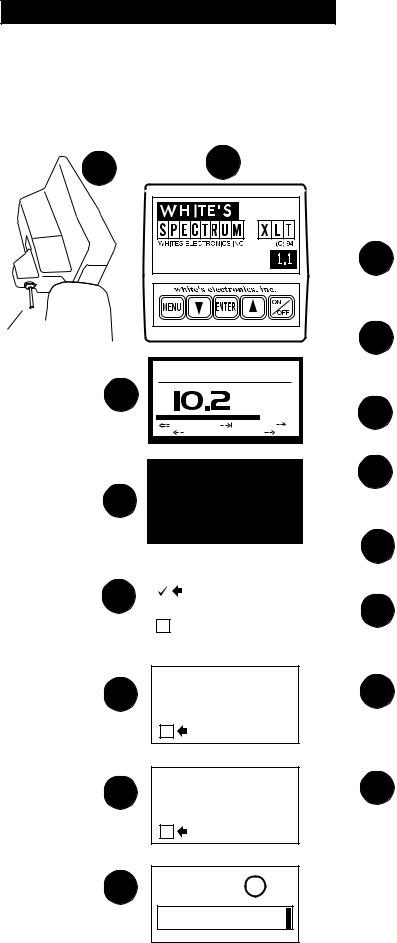
XLT® Quick Start Instructions |
|
|
|
After you have assembled the XLT® and inserted the |
|||
|
|
|
|
battery pack, follow these simple steps to start |
|
|
|
|
|
treasure hunting! |
|
|
|
|
SOFTWARE |
1 |
With the TRIGGER in the center position, |
|
|
|
VERSION # |
press the ON/OFF control and an automatic |
|
|
|
|
|
|
|
|
|
|
|
|
sequence will begin. |
TRIGGER |
|
|
|
2 |
The display will momentarily show an |
|
|
|
opening screen which lists the software |
||
UNDER |
|
|
|
|
|
|
|
|
|
version. |
|
DISPLAY POD |
|
BATTERY CHECK |
|
||
|
|
|
|||
CENTER |
3 |
|
VOLTS |
|
|
POSITION |
|
3 |
The display then shows a battery check |
||
|
|
||||
|
|
|
screen. |
||
|
|
NICAD |
ALK |
|
|
|
6 LOW |
OK |
|
14.0 |
|
|
|
|
|
|
|
|
|
|
|
|
MAIN MENU |
PG. 1/1 |
|
|
|
4 |
|
|
|
PRESET PROGRAMS |
|
|
|
|
|
|
|
BASIC ADJUSTMENTS |
|
||
|
|
|
|
PRO OPTIONS |
|
||
|
|
|
|
|
|||
|
|
|
|
|
|
|
|
|
(press ENTER) |
|
|
|
|||
|
|
|
|
|
|
|
|
|
|
|
|
|
|
|
|
5 |
|
|
PROGRAMS |
PG. 1/3 |
|
||
|
|
|
COINS |
|
|
|
|
|
|
|
|
|
|
||
|
|
|
|
|
|
||
|
|
|
|
COIN & JEWELRY |
|
||
|
|
|
|
JEWELRY/BEACH |
|
||
|
(press ENTER) |
|
|
|
|||
RAISE LOOP TO WAIST 6 LEVEL THEN PRESS
ENTER
4 |
The last automatic display screen to appear |
|
is the MAIN MENU. Press the ENTER |
||
|
||
|
control. ("BEEP") |
|
5 |
The Preset Program COINS will appear on |
|
|
the MENU. Press ENTER . ("BEEP") |
You will be prompted to raise the search 6 coil (loop) to waist level. Press ENTER .
This air balances the XLT® . ("BEEP")
Next, the ground balance prompt appears 7 asking you to lower the search coil (loop) to
the ground. Press ENTER. Ground mineralization will be balanced out. ("BEEP")
(press ENTER)
LOWER LOOP TO GROUND 7 SURFACE THEN PRESS
ENTER
(press ENTER)
8 +88 |
|
25¢ |
-95 |
0 |
+95 |
The last screen will be the live search
8 screen. You will hear the THRESHOLD "hum". Sweep the search coil over the ground and listen for a solid repeatable/ consistent beep, then look at the display. The icons tells what likely coin lies below. V.D.I. number/chart on top of control box and SignaGraph® provide greater detail. Squeeze the trigger for pinpointing and depth and it's time to dig!
8 |
(LIVE SEARCH SCREEN) |
|
Chapter 3 XLT® Quick Start
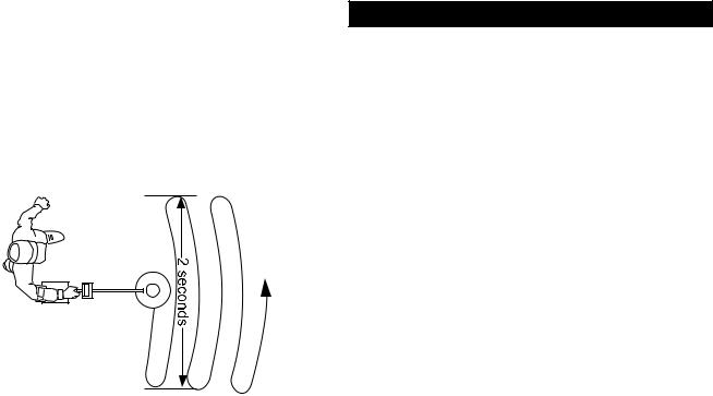
Search Fundamentals
The loop/search coil must be in motion (sweeping from side-to-side) for this instrument to respond to metal. Practice a smooth sweep of the loop from side-to-side keeping the loop close to the ground throughout the swing. Each pass of the loop should take approximately two seconds from right to left, two seconds to return from left to right.
Walk forward slowly. Take small steps no greater than half normal strides. Make sure each pass of the loop overlaps the last by at least half the length of the loop. Do not lift the loop at the end of each swing. Keep it close to the ground at all times.
To become comfortable with sweeping the loop takes some practice. Try to loosen up and find a comfortable grip on the handle. Premature fatigue may result from gripping the handle too tightly, improperly adjusted rod or elbow support, and limited body movement. Hold the handle loosely. Adjust the rod and elbow support for comfort and keep the elbow strap loose. Use your arm, shoulder and even your back a little to allow a smooth even sweep of the loop.
Now that you're sweeping the loop smoothly over the ground, you will notice that the detector starts making sounds (beeps). Not all sounds are good targets; some trash targets also make the detector beep.
As the loop is swept over the ground, ignore the display and concentrate on the sounds the detector makes.
As the loop is passed over metal that is likely trash, the sound will be inconsistent. Trash targets typically produce a shorter, sputter-type sound, that is often broken or double in nature. Place a steel-pop bottlecap on the ground. Pass the loop over it several times to become familiar with this sound at different loop sweep speeds. Note that an aluminum twist-off bottlecap cannot be used as it is a different type of target. Also note that very old rusty bottle caps may start reading as quarters due to the elimination of the iron alloy through deterioration. Once familiar with the sound typical bottle caps produce, an operator may pass over such targets and continue searching without consulting the display information, saving more time for evaluating possible good targets.
As the loop passes over metal that is likely a good target, a more consistent and smooth sound will be heard. A good target typically produces a longer, more solid sound. Place a quarter on the ground and sweep the loop over it several times to become familiar with the sound of a good target.
Why Air/Ground Balance?
When the display prompts you to, AIR BALANCE by holding the loop at waist level and press ENTER. The XLT® 's circuits are being prepared for ground balancing by measuring temperature and other variables that affect electronic circuits. The XLT® "beeps" and you lower the search coil to the distance above the ground that you will be searching. Press ENTER to have the XLT® "cancel/track out" or GROUND BALANCE the ground mineralization. The XLT® then automatically "tracks out" the varying mineralization as you continue to search.
9
Chapter 3 XLT® Quick Start
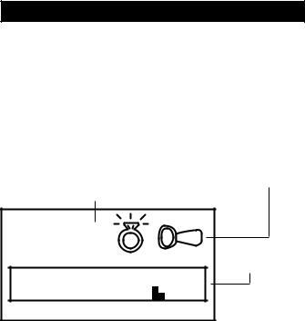
Live Search Screen - what is it telling me?
VISUAL |
|
POSSIBLE TARGET |
DISCRIMINATION |
|
IDENTITIES |
INDICATION-V.D.I. NUMBER |
("ICONS") |
|
("TARGET REFERENCE NUMBER") |
||
+48 |
|
SIGNAGRAPH |
|
|
BARGRAPH |
-95 |
0 |
+95 |
1.V.D.I. Visual Discrimination Indication ("target reference number")
In the upper left hand-side of the display there is a V.D.I. number that corresponds to the V.D.I. SCALE painted on the top right-hand side of the control box. It also corresponds to the Discriminate Edit feature allowing you to reject or accept targets based on their V.D.I. reference number. There are "+" numbers for non-ferrous (not of iron) targets, and "-" numbers for ferrous (iron) targets. Rejected V.D.I. numbers may not appear if the VISUAL
DISCRIMINATION feature is ON. Reasonably consistent V.D.I. reference numbers (± five digits),
in a desirable area of the chart is a vote for digging the target.
2.Possible Target Identities ("Probable or most likely Target")
To the right of the V.D.I. number, possible target identities will be represented graphically. These graphics are called ICONS. A fairly consistent indication of a desirable target is another vote to dig the target. One or two possible target icons may appear. There is significance to which icon appears first. The first target to appear is always the most likely, the second is another possibility slightly less likely than the first.
3.SignaGraph™
The SignaGraph™ at the bottom of the display provides a final vote as to whether or not the target should be dug.
A.Sweep the loop over the target several times and look at the SignaGraph™. The SignaGraph™ automatically clears itself (FADE RATE) so that it doesn't fill the screen with information from past loop sweeps. An operator has limited time to look at the SignaGraph™. If you want to look at the information again, sweep the loop over the target several more times. The fading of the
SignaGraph™ information can be slowed or speeded (FADE RATE) to operator preference. This is completed in the PRO OPTIONS under DISPLAY. Automatic AVERAGING and/or ACCUMULATING of SignaGraph™ information is also available (See PRO OPTIONS).
B.Valuable targets will show up on the positive side of the graph. The positive area of the chart is the section located to the right of the zero.
C.Look for consistency. In ideal conditions, coins and jewelry produce one or two bars to the right of zero. Trash produces several bars, sometimes on both sides of zero.
D.In less than ideal conditions, coins may produce a wider pattern of bars. Most trash targets produce a recognizably different pattern than valuable targets.
E.One of the most visual benefits of the
SignaGraph™ is the ability to show a smear pattern on iron targets that often fool the other methods of identification. An iron target will likely show definite bars on both the negative and positive sides of the SignaGraph™, often smearing all the way across the entire chart. Valuable targets should not produce such obviously wide patterns. In very bad ground conditions, a good target may have a few small bar segments in the negative area due to mineralization. However, the pattern will show mostly positive bars, in a fairly narrow tall group.
10
Chapter 3 XLT® Quick Start
Live Search Screen Samples
+19 |
|
|
|
|
|
|
|
|
Nickle, or |
+80 |
|
|
|
|
|
|
|
|
|
Penny or a |
||
¢ |
|
|
|
|
possible ring. |
¢ |
10¢ |
|
|
|
dime. If the |
|||||||||||
|
|
|
|
Sometimes a |
|
|
|
screw cap and |
||||||||||||||
5 |
|
|
|
|
small (or half) |
1 |
|
|
|
|
|
|
|
|
penny ICON |
|||||||
|
|
|
|
|
|
|
|
|
|
pull tab will |
|
|
|
|
|
|
|
|
|
|
|
are displayed, |
|
|
|
|
|
|
|
|
|
|
|
|
|
|
|
|
|
|
|
|
|
||
|
|
|
|
|
|
|
|
|
|
produce this |
|
|
|
|
|
|
|
|
|
|
|
the target can |
|
|
|
|
|
|
|
|
|
|
|
|
|
|
|
|
|
|
|
|
|
||
|
|
|
|
|
|
|
|
|
|
indication |
|
|
|
|
|
|
|
|
|
|
|
be an Indian |
-95 |
0 |
|
|
|
+95 |
-95 |
0 |
+95 |
||||||||||||||
|
|
|
|
|
|
|
|
|
|
|
|
|
|
|
|
|
|
|
|
|
|
Head or zinc |
|
|
|
|
|
|
|
|
|
|
|
|
|
|
|
|
|
|
|
|
|
|
penny. |
|
|
|
|
|
|
|
|
|
|
Quarter. Could |
|
|
|
|
|
|
|
|
|
|
|
Dollar. Large |
+88 |
|
|
|
|
|
|
|
|
+93 |
|
|
|
|
|
|
|
|
|
||||
25¢ |
|
|
|
|
be a worn half, |
1$ |
|
|
|
|
|
|
|
|
non-iron can |
|||||||
|
|
|
|
|
|
or large silver |
|
|
|
|
|
|
|
|
|
|
also produce |
|||||
|
|
|
|
|
|
|
|
|
|
jewelry. |
|
|
|
|
|
|
|
|
|
|
|
this indication |
|
|
|
|
|
|
|
|
|
|
|
|
|
|
|
|
|
|
|
|
|
|
(large brass jar |
|
|
|
|
|
|
|
|
|
|
|
|
|
|
|
|
|
|
|
|
|
|
lids). |
|
|
|
|
|
|
|
|
|
|
|
|
|
|
|
|
|
|
|
||||
-95 |
0 |
|
|
|
+95 |
|
-95 |
0 |
+95 |
|
||||||||||||
|
|
|
|
|
|
|
|
|
|
|
|
|
|
|
|
|
|
|
|
|
|
|
|
|
|
IRON. REJECT |
+95 |
|
|
|
|
|
targets will |
|
|
|
|
|
|
|
|
|
|
|
|
|
produce only a |
|
|
|
|
|
|
SpectraGraph™ |
|
|
|
|
|
|
if VISUAL |
|
|
|
|
|
|
DISC. is ON |
|
|
|
-95 |
0 |
+95 |
|
-95 |
0 |
+95 |
IRON. +95 ACCEPTED or VISUAL DISC. OFF
-18 |
|
|
|
IRON. -18 |
+10 |
|
|
|
|
|
|
Foil. Possible |
||||||
|
|
|
ACCEPTED or |
|
FOIL |
|
|
ring. +10 |
||||||||||
|
|
|
|
|
|
|
|
|
|
|
|
|
|
|||||
|
|
|
|
|
|
|
|
|
VISUAL DISC. |
|
|
|
|
|
ACCEPTED or |
|||
|
|
|
|
|
|
|
|
|
|
|
|
|
|
|
|
|
||
|
|
|
|
|
|
|
|
|
OFF. |
|
|
|
|
|
|
|
|
VISUAL DISC. |
|
|
|
|
|
|
|
|
|
|
|
|
|
|
|
|
|
|
OFF. |
|
|
|
|
|
|
|
|
|
|
|
|
|
|
|
|
|
|
|
|
|
|
|
|
|
|
|
|
|
|
|
|
|
|
|
|
|
|
|
|
|
|
|
|
|
|
|
|
|
|
|
|
|
|
|
|
|
-95 |
|
|
|
|
0 |
+95 |
|
-95 |
0 |
|
|
|
+95 |
|
||||
|
|
|
|
|
|
|
|
|
|
|
|
|
|
|
|
|
|
|
+30 |
|
Pull tab. |
+48 |
|
Ring. Possible |
|
Possible ring. |
|
pull tab. +48 |
||
|
|
+30 AC- |
|
|
ACCEPTED or |
|
|
CEPTED or |
|
|
VISUAL DISC. |
|
|
VISUAL DISC. |
|
|
OFF. |
|
|
OFF. |
|
|
|
-95 |
0 |
+95 |
-95 |
0 |
+95 |
11
Chapter 3 XLT® Quick Start
"X" THE LOOP TO "PINPOINT" THE TARGET
SQUEEZE TRIGGER
DEPTH SCREEN
DISPLAYED WHEN 10.5" THE TRIGGER
IS SQUEEZED
+ - 1 2 - + - + - 9 - + - + - 6 - + - + - 3 - + - + - 0
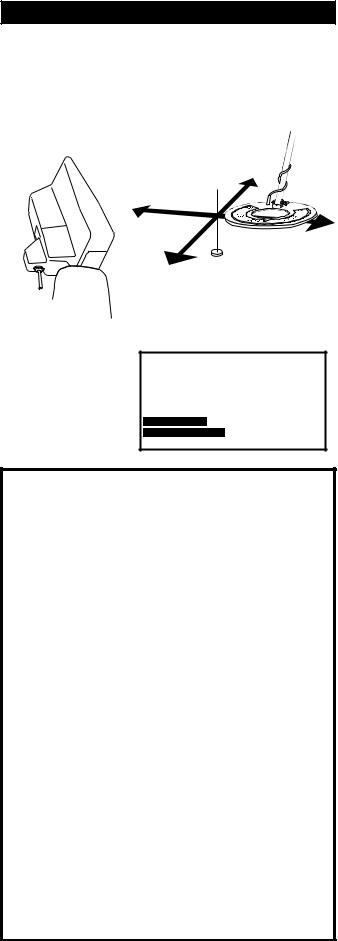
Advanced Pinpointing Techniques
1.Targets that are near the surface, because they give a wider response, are harder to pinpoint than deep targets. If the trigger is held and the loop swept over the area, you may note a shallow depth indication. Lifting the loop slightly above the ground, releasing and resqueezing the TRIGGER and again "X" ing the target will aid pinpointing.
2.In the Basic Adjustments, DC Sensitivity (non-motion) directly controls the pinpointing mode. Lower DC Sensitivity settings pinpoint shallow targets better.
3.In the PRO OPTIONS under AUDIO, V.C.O. (Voltage Controlled Oscillator) significantly aids pinpointing.
4.The depth reading has two indication bars. The top bar shows the current distance from the target, and the bottom bar shows a memory of the strongest reading. These two bars will be even with each other when the loop is directly over the center of the target.
Pinpointing the Target
Once the decision has been made to dig, move the loop off to one side of the target area, squeeze and hold the TRIGGER on the handle, and "X" the loop over the spot where you believe the target to be. Note that the TRIGGER also has a locked forward position that accomplishes the same thing as squeezing and holding it.
While the TRIGGER is being held, the loop doesn't need to be moving to detect the target. The loop may be moved slowly over the area. The display will indicate depth in inches and will also show the strongest reading to aid in pinpointing exactly where to dig. The shallowest reading on the depth display, the loudest sound coming from the speaker, and the two bars lining up with each other, indicate the center of the target. Don't forget to "X" the target as pinpointing cannot be accurate unless the target is swept from at least two different directions. Once pinpointing is complete, release the TRIGGER, or return it to the center position.
Pinpointing takes practice. The standard loop provided with the Spectrum® is a high-powered, 9.5 inch design. This loop's strongest traits are in the detection depth and ground coverage areas. If pinpointing becomes difficult or critical, an optional smaller loop is suggested. The smaller loops have advantages in high trash areas and pinpointing, but will not detect as deep as the standard 9.5 inch size.
12

Chapter 3 XLT® Quick Start
Ready to Dig
Permission - Prior to searching and digging you must have permission to search private property, from the owner or caretaker.
Laws - Know the laws that apply to the area you are going to search. Laws vary a great deal with the City, County, State, and Country, regarding the use of metal detectors. Be respectful of private property, public property, and the laws which govern the use of metal detectors.
Tools - Care must be taken to dig in a way that is friendly to the landscape. Tools and methods vary a great deal with the area, season, and types of target you are recovering. Check with your dealer for recommended tools and methods for your area.
Trash - When searching, remove all trash you come across. This not only makes your future searches of the area more productive; it promotes the hobby of metal detecting.
Get Involved - Your dealer knows of metal detecting clubs and organizations which promote and protect the hobby. A club is a great way to not only learn good detecting habits, but to gain permission to search areas as a group as well as have organized competition hunts.
Factory Preset Programs
Reached from the MAIN MENU, the factory PRESET PROGRAMS give a quick start for:
Coins: general purpose settings, discriminates (rejects) most common junk items like nails, foil, pull tabs, and hot rocks; and responds to most coins and large jewelry. Use in lawns, parks, and playgrounds where lots of trash rejection is desired.
Coin & Jewelry: less discrimination (less trash rejection), desirable because of the high degree of variance found in jewelry alloys. More digging required. Good program for lawns, parks, and playgrounds. Use screen more than sound.
Jewelry & Beach: similar to Coin & Jewelry, but Pro Options are changed for salt water.
Relic: even less discrimination than Coin & Jewelry or Jewelry & Beach, all types of metals except small iron items like nails, and some stainless steel. Brass, lead, aluminum, as well as copper, silver, and gold all respond solidly. Ferrous (iron), such as large nails, weapons, and cannon ball fragments will also respond . Suitable for all significant targets and separate ferrous/non-ferrous by display indications.
Prospecting: NO AUDIO DISCRIMINATION. All metals respond with beep. But V.D.I. numbers show only for metals that could be gold. Dig only V.D.I. number (possibility gold) targets and avoid iron. Targets which cause an audio response, without causing a V.D.I. number to appear on the display, are not likely to be gold nuggets. Although high-frequency gold-shooting detectors will respond better, this mode will offer good results for the occasional nugget hunter by responding to nuggets in the nine-grain and heavier category.
13
Chapter 4 XLT® Basic Adjustments
Basic Adjustments
Basic Adjustments - what do they do?
1.TARGET VOLUME - How loud a target beeps when detected.
2.AUDIO THRESHOLD - The slight hum or background sound heard continuously during searching.
3.TONE (AUDIO FREQUENCY) - Selects the frequency or pitch of sound the detector produces.
4.AUDIO DISCRIMINATION - The ability to reject trash, different sounds for different types of targets.
5.SILENT SEARCH - The ability to operate without the threshold or background hum.
6.MIXED-MODE - DC non-discriminate mode, working simultaneously with AC discrimination mode.
7.A.C. SENSITIVITY - Degree instrument is responsive to signals in the discriminate (motion) modes.
8.D.C. SENSITIVITY - Degree instrument is responsive to signals in non-discriminate (non-motion) modes.
9.BACKLIGHT - Used in dark conditions to light the display improving visibility.
10.VIEWING ANGLE - Adjusts the display for low or high temperature visibility.
MAIN MENU PG. 1/1
PRESET PROGRAMS
 BASIC ADJUSTMENTS
PRO OPTIONS
|
|
|
|
|
|
|
|
|
|
|
|
|
|
|
|
(press ENTER) |
|
||||||||||||
ADJUSTMENT |
|
|
|
|
|
|
|
|
|
|
|
|
|
|
|
|
|
|
|
|
|
|
|
|
|
|
|
|
|
|
|
|
|
TARGET VOLUME |
|
|
|
|||||||
EXAMPLE: |
|
|
|
|
|
|
|
|||||||
|
|
|
|
|
|
|
|
|
|
56 |
|
|
||
|
|
|
|
|
|
|
|
|
|
|
|
|||
|
|
|
|
|
|
|
||||||||
|
|
|
|
|
|
|
|
|
|
|
||||
|
|
|
MIN |
MAX |
|
|||||||||
|
|
|
|
|
|
|
|
|
|
|
|
|
|
|
|
(press ENTER) |
|
||||||||||||
RECTANGLE AROUND |
|
|
|
|
|
|
|
|
|
|
|
|
|
|
|
|
|
TARGET VOLUME |
|
||||||||||
THE TITLE MOVES TO |
|
|
|
|
||||||||||
THE SETTING |
|
|
|
|
|
|
|
|
|
|
|
|
|
|
|
|
|
|
|
|
|
|
|
|
|
|
|
|
|
USE ARROW KEYS TO |
|
|
|
|
|
|
|
|
56 |
|
|
|||
|
|
|
|
|
|
|
|
|||||||
ADJUST THE SETTING |
|
MIN |
MAX |
|
||||||||||
UP OR DOWN |
|
|
|
|
|
|
|
|
|
|
|
|
|
|
|
TIP - To quickly increase to |
|
||||||||||||
|
maximum, hold ENTER and |
|
||||||||||||
|
press ARROW up. To quickly |
|
||||||||||||
|
decrease to minimum, hold |
|
||||||||||||
|
the ENTER and press |
|
||||||||||||
|
ARROW down. |
|
||||||||||||
ADJUSTMENT
EXAMPLE: SILENT SEARCH

 ON
ON
 OFF
OFF
TO CHANGE PRESS ENTER
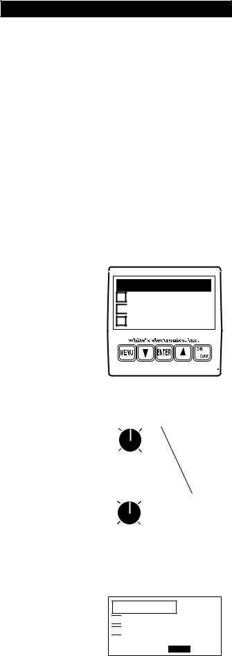
Basics of Basic Adjustment
After you have had some field experience, you may want to make some changes to the basic settings of your detector. From the search mode press MENU. At this point, the MAIN MENU will appear on the display. Use the ARROW controls to move the pointer to Basic Adjustments, and then press ENTER. You may now use the ARROW down control to scroll through the Basic Adjustments.
Using the first adjustment screen (TARGET VOLUME) as an example, the screens with a graphic control knob require you to first press ENTER then use the ARROW up and down controls to adjust. Note when ENTER is pressed the square around the title moves to the setting, indicating you are ready to make adjustments with the ARROW controls. After adjusting press MENU and use the ARROW controls to continue viewing / setting other Basic Adjustments, or squeeze and release the TRIGGER to begin searching
Adjustment screens with an on/off selection need only for you to press ENTER to change setting. Pressing ENTER again changes back to the original setting.
14

Chapter 4 XLT® Basic Adjustments
More Basics
All the MENU items are tied together so that the ARROW up and down controls scroll through every adjustment screen. If you continue to press the ARROW down you can go beyond the last BASIC ADJUSTMENT (View Angle) and into the PRO OPTIONS. If the ARROW up control is pressed after VOLUME, you will be scrolling backwards through the options starting with the end of the Preset Programs, then the MAIN MENU, then the end of the PRO OPTIONS.
An important feature of the ARROW controls; If a BASIC ADJUSTMENT has been made (for example Volume) and the trigger has been squeezed and released to return to a search mode, you can return to the volume adjustment simply by pressing either of the ARROW controls. This shortcut returns to the last adjustment that was made thereby allowing an operator to switch directly from a search mode to the adjustment currently being fine tuned. This feature is desirable as you start using BASIC ADJUSTMENTS or PRO OPTIONS that are located further down the menu listings, or any adjustment that may require some trial and error to find the appropriate setting.
If care is taken to use a desired adjustment screen last (just prior to squeezing and releasing the TRIGGER for a search mode), Custom Programs (such as a competition hunt program) can use this ARROW RETURN feature to allow quick easy access to the most used feature (Transmit Frequency). Use that feature (adjustment screen) last, just prior to squeezing and releasing the TRIGGER for searching. Then during searching, press either ARROW to return directly to that adjustment screen.
"Hot Key" Shortcuts
"HOT KEYS" will save time as they allow easy access, from the search mode, to the most needed adjustments. They are painted on the bottom of the control box for field reference.
COIN PROGRAM - Squeeze & release TRIGGER after automatic battery check.
SCROLL OPTION - After battery check, use ARROWS to scroll all the current settings / menus.
AIR/GROUND BALANCE - In search mode, press ENTER to re-Air/Ground Balance.
GROUND BALANCE ONLY - While searching, hold the TRIGGER and press ENTER.
BATTERY CHECK - While searching, hold the TRIGGER and press ARROW down. Sqeeze and release TRIGGER to return to searching.
REVERSE DISPLAY - While searching, hold the TRIGGER and press ARROW DOWN. Press ARROWs for light/dark background. Light or dark background will not change battery life. It will make the display easier for some to read, particularly in certain light conditions. It will work in combination with backlight. Reversed display is only accessible through the "HOT KEYS".
BACKLIGHT - In search mode, hold TRIGGER and press MENU. Release TRIGGER, press ARROWS to set.
VIEW ANGLE - While searching, hold the TRIGGER and press ARROW up. Release TRIGGER, press ARROWS to set.
15
Chapter 4 XLT® Basic Adjustments
Custom Programs - Saving your Basic and Pro Option adjustments for future use.
Save custom settings in any one of four custom program positions. They will remain permanently in the XLT® memory regardless if the machine is turned off or the battery removed. Custom Programs can be changed at any time by saving new settings over a previously saved custom program.
1 SQUEEZE |
THEN PUSH |
|
TRIGGER |
MENU |
|
2 |
MAIN MENU |
PG. 1/1 |
|
PRESET PROGRAMS |
|
|
BASIC ADJUSTMENTS |
|
|
PRO OPTIONS |
|
PRESS ENTER FOR PRESET PROGRAMS |
||
|
PROGRAMS |
PG. 1/3 |
|
COINS |
|
|
COIN & JEWELRY |
|
|
JEWELRY/BEACH |
|
SCROLL DOWN WITH ARROW KEYS |
||
|
PROGRAMS |
PG. 2/3 |
|
RELIC |
|
|
PROSPECTING |
|
|
CUSTOM PROGRAM 1 |
|
PRESS ENTER |
|
|
3 |
C.P. OPTIONS |
PG. 1/1 |
|
LOAD |
|
|
SAVE |
|
|
NAME |
|
PRESS ENTER |
|
|
4 |
PROGRAMS |
PG. 2/3 |
|
RELIC |
|
|
PROSPECTING |
|
|
TRASH |
|
USE THE ARROW KEYS TO SCROLL THE FLASHING SYMBOLS, PRESS ENTER
PROGRAMS PG. 2/3
RELIC
PROSPECTING

 TRASHY PARKS
PRESS MENU
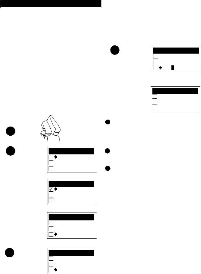
1. Once all of the changes you desire have been made to any Preset Program or existing Custom Program, squeeze and release the TRIGGER as if to search.Then push MENU for MAIN MENU.
2. Use the ARROW controls to select one of the four Custom Programs then press ENTER.
33. You now must make one of three choices (use the ARROW controls to make your selection):
A.LOAD will activate a prior custom program stored in that position. After you have SAVED or NAMED a program, you can select LOAD and press ENTER, to use that program.
B.SAVE saves your current settings in that custom position with either a generic name or a prior custom name you may have applied.
Selecting SAVE and pressing ENTER saves the current program.
C.NAME is the preferred method. Select NAME and press ENTER. You may now use the ARROW and ENTER controls to name your custom program. NAME automatically SAVES, once you have chosen a name and pressed MENU.
16

Chapter 4 XLT® Basic Adjustments
4. To NAME, use the ARROW controls to select the first symbol, number, or letter of the name and press ENTER. Use the ARROW controls to select the second symbol, number, or letter of the name, press ENTER. And so on using up to sixteen digits. To leave a space, use the ARROWS to select the point where no symbol or letter appears and press ENTER. If you make a mistake and press ENTER when the digit is not as you desire, simply keep pressing ENTER until that digit is again flashing, then use the ARROWs to select the correct digit and again press ENTER. It is wise to name the custom program something that relates to what it is used for. For example "TRASHY PARKS", "SMALL LOOP", "GHOST TOWN", "NIGHT HUNT", "COMPETITION", etc. Once the name is fully assembled press MENU.
5.Once you have SAVED and pressed ENTER, or NAMED and pressed MENU, there are four directions you can go:
A.Squeeze and release the TRIGGER to continue searching using your new custom program.
B.Press ENTER, select LOAD and press ENTER to continue searching using your new custom program.
C.Press MENU to return to choose or develop a different program than what you stored.
D.Turn the detector OFF.
6.When the detector is turned back on, regardless of whether a battery pack was left in the detector or
not, your custom program will be ready for you to use again and again. Simply select it, press ENTER, select LOAD, and press ENTER again. Follow the onscreen instructions for Air/Ground Balance and then search.
7.If you SAVE or NAME a program, then decide you no longer want to keep it, you can replace it with a
new program using the same procedure as described above. The old program can only be erased when a new program is stored in that position.
8. You can NAME a custom program and at a later date replace the program while maintaining the same name. Develop the changes first to any program, then use the SAVE method which maintains the old name while storing the new program. To keep the same program with a new name, first LOAD that custom program, Air/Ground Balance, then press MENU and go to that custom position and press ENTER. Now select NAME and press ENTER. You can now develop a new name for the old program.
Other Custom Program info
Ground Balance - When a Custom Program is stored, the Ground Balance setting last used with that program is also stored. This has advantages particularly for those who manually set the Ground Balance for speciality applications. The automatic Air/Ground Balance sequence will always override manual settings. To access the last Ground Balance setting used with a Custom Program, first select the desired Custom Program then press ENTER. Select LOAD and press ENTER. Do not Air/Ground Balance as the display suggests, simply squeeze and release the TRIGGER. The last Ground Balance setting will then be in use. If an appropriate Air/ Ground setting is not available, the instrument will automatically require a new Air/Ground Balance.
Return ARROW Key - The last Basic Adjustment or Pro Option screen used is remembered by your Custom Program. From the search mode, either ARROW control will access the last Basic Adjustment or Pro Option screen used. This allows easy access to the most used adjustment (such as Transmit Frequency) for a custom competition hunt program.
17
 Loading...