

Page 1
®
PulseScan TDI Owner’s Guide 1
Owner’s
GuIDe
™
TDI
White’s Electronics, Inc. -
Manufacturers of the World’s Finest Metal Detectors
Page 2

2 PulseScan TDI Owner’s Guide
Page 3

PulseScan TDI Owner’s Guide 3
CONTENTS -
Assembly .....................................................................................................................4
Engineering Description .....................................................................................7
Charging Systems and Batteries ................................................................... 8
CONTROLS ......................................................................................................... 10
Power ..........................................................................................................................10
Threshold ..................................................................................................................11
Target Conductivity ............................................................................................13
Frequency .................................................................................................................16
Pulse Delay ...............................................................................................................17
Gain..............................................................................................................................19
Ground Balance ....................................................................................................21
INITIAL SET-UP ........................................................................................................25
More Variable Audio ...........................................................................................28
More Pulse Delay..................................................................................................30
White’s Warranty .................................................................................................32
White’s Warranty UK ..........................................................................................35
White’s Warranty Service Centers .............................................................38
Page 4
4 PulseScan TDI Owner’s Guide
ASSEMBLY -
Cable Retainer
õ
õ
Clevis Lower Rod
õ
S-rod
Washers between each
loop ear & clevis
õ
Search Coil
õ
Camlock
õ
Loop Connector
Control Box
HIP MOUNTABLE
õ
õ
Battery
Compartment
Door
õ
Headphone
Jack
õ
õ
Battery
Compartment
Latches
Page 5

PulseScan TDI Owner’s Guide 5
ASSEMBLY INSTRUCTIONS -
1. Remove all parts from the shipping carton and check assembly page to
make sure all parts are present.
2. Install black rubber washers on fiber clevis/lower rod, insert clevis lower rod
onto loop ears. Use only nonmetallic washers, fiber bolt, and fiber thumbnut to
secure loop/search coil to clevis/lower fiber rod.
3. Unlock “S” rod cam-lock and insert clevis/lower rod into curved “S” rod so
that stainless steel spring clip buttons line up and lock into one of the adjustment holes in the curved “S” rod. Turn cam-lock to secure. The second or third
adjustment holes are suitable for average sized adults. Individuals six feet or
taller should use fully extended position. Individuals well oversix feet tall should
purchase the optional Tall Man Rod accessory.
4. Unravel loop cable and wind the cable around the clevis and rod assembly,
first revolution over the top of the rod. Wind cable all the way to the top of the
curved “S” rod, about five revolutions. Use the black cable retainers, one near
the loop, and one near the top of the curved “S” rod, to hold the loop cable in
place.
5. Unlock control box rod cam-lock and insert curved “S” rod so that stainless
steel spring clip buttons line up and lock into the rod on top of the control box.
The “S” rod is designed to curve up towards the display. However those who
prefer to sweep the loop close to their feet may desire to assemble the “S” rod to
curve down towards the ground. Turn cam-lock to secure. Plug loop connector
into control box, screw lock ring to secure.
6. Grip the instrument by the handle, with your arm in the elbow cup with strap
and sweep the loop/search coil over the floor. If the instrument fit feels uncomfortable, readjust clevis/lower rod length with spring clip button and cam-lock so
that search coil can be held near the floor without requiring stooping over.
7. Remove the protective paper from the two black arm cup foam pads.
Carefully align pads on the inside of the elbow cup, one on each side of the
center rod, and press firmly into place.
Page 6

6 PulseScan TDI Owner’s Guide
8. Adjust the elbow cup strap so that it is loose enough for you to slide
your arm in and out without loosening each time you want to set the detector
down. The elbow cup strap provides extra leverage and control. However,
some prefer not to use it.
9. Install battery as described in next section.
10. It should be noted at this point that the detector may not work as expected
indoors due to the high degree of metal used in modern construction. It is best to
tune and practice out-of-doors to ensure stable, predictable results. Additionally,
freshly buried targets will rarely produce the normal depth results of targets that
have been naturally lost and settled in undisturbed ground. Due to the abnormality caused by digging a hole in the ground matrix, and the lack of the normal
target to soil reactions, it may take a number of years for freshly-buried targets to
respond at true depths. The best way to determine true detection depth is in real
search conditions.
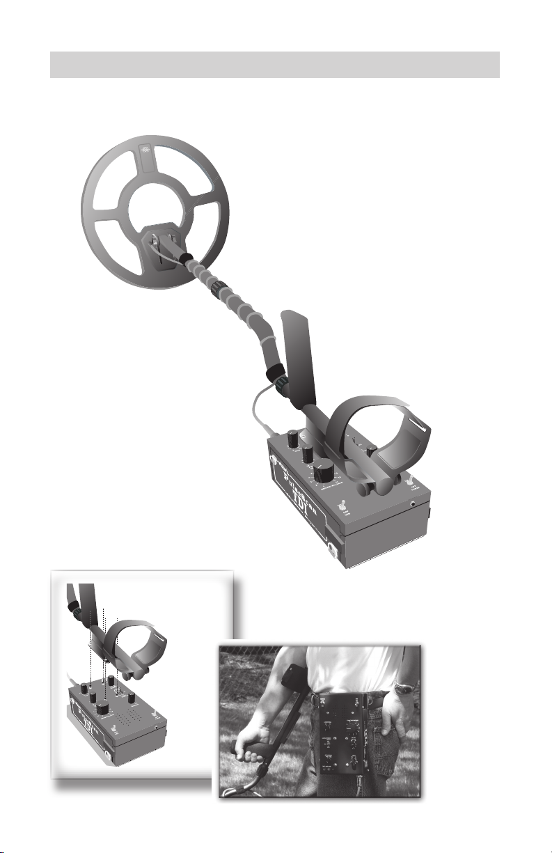
11. Hip Or Chest Mounting a) On top of the control box, the rod-to-case mounting plate has four
Phillips head screws. Remove these four screws and remove the rod/loop/arm
cup assembly from the top of the control box. To prevent moister/dirt from
entering the control box, replace the four screws on top the control box (sink all
the way) without the rod or mounting plate.
b) Adjust/unravel enough loop cable wrapped around the rod, to allow
slack to sweep the rod/loop and connection with the control box. Use two velcro
straps provided to secure loop cable around rod.
c) The control box can be worn on ones chest, hip, or waist based on
personal preference. Belt hook provided on bottom of control box as well as
four “D” rings to attach camera/dog leash connector type straps.
Page 7

PulseScan TDI Owner’s Guide 7
ENGINEERING DESCRIPTION -
Although the new Pulsescan TDI was designed with the Gold Prospector in mind, its features and performance will be just as valuable to Beach & Relic
Hunters.
During the development of the PulsescanTDI, we kept in mind the
comfort of the user by designing an instrument which would be as light as possible, and easy to operate in addition to producing outstanding performance at an
affordable price.
The Pulsescan TDI is a deep searching, very sensitive pulse induction metal detector which incorporates a true user controlled manual ground
balancing feature, a byproduct of which is the ability to produce an audio tone,
for possible identification of the detected target. User controlled manual balancing of the ground has the additional benefit of giving the user the option of fine
tweaking for different situations, thus increasing the probability of hearing the
faint signals of small or deep targets. The Manual Ground Balance feature of
the Pulsescan TDI can be turned off if the ground mineralization is not severe
enough to require it, as then the pulse circuitry itself is able to ignore most
ground mineralization by its very nature. In this situation, with the Ground
Balance toggle off, there is no audio tone variation - all metal targets will sound
alike, and additional depth can be attained.
White’s is proud to have been able to work with Eric Foster, of Oxford,
England, who enjoys the world wide reputation of being the “Father of Pulse
Technology”.
Page 8
8 PulseScan TDI Owner’s Guide
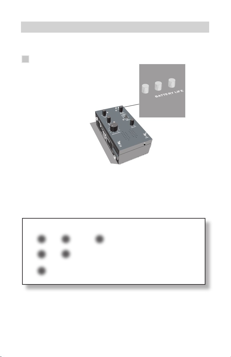
CHARGING SYSTEMS, BATTERIES AND BATTERY CONDITION -
Batteries and Charger
The PulsescanTDI uses a rechargeable Lithium Ion battery pack as the power
source. This type of battery can supply the high current levels required by the
detector and weights much less than other battery packs that have the same
power characteristics. It supplies a nominal voltage of 14.4 volts and approximately 500ma of current to the detector during operation.
RED YELLOW
GREEN
õ
ò
òò
OPERATIONAL RANGE
õ
ò
ò
CAUTION - Low Battery
õ
ò
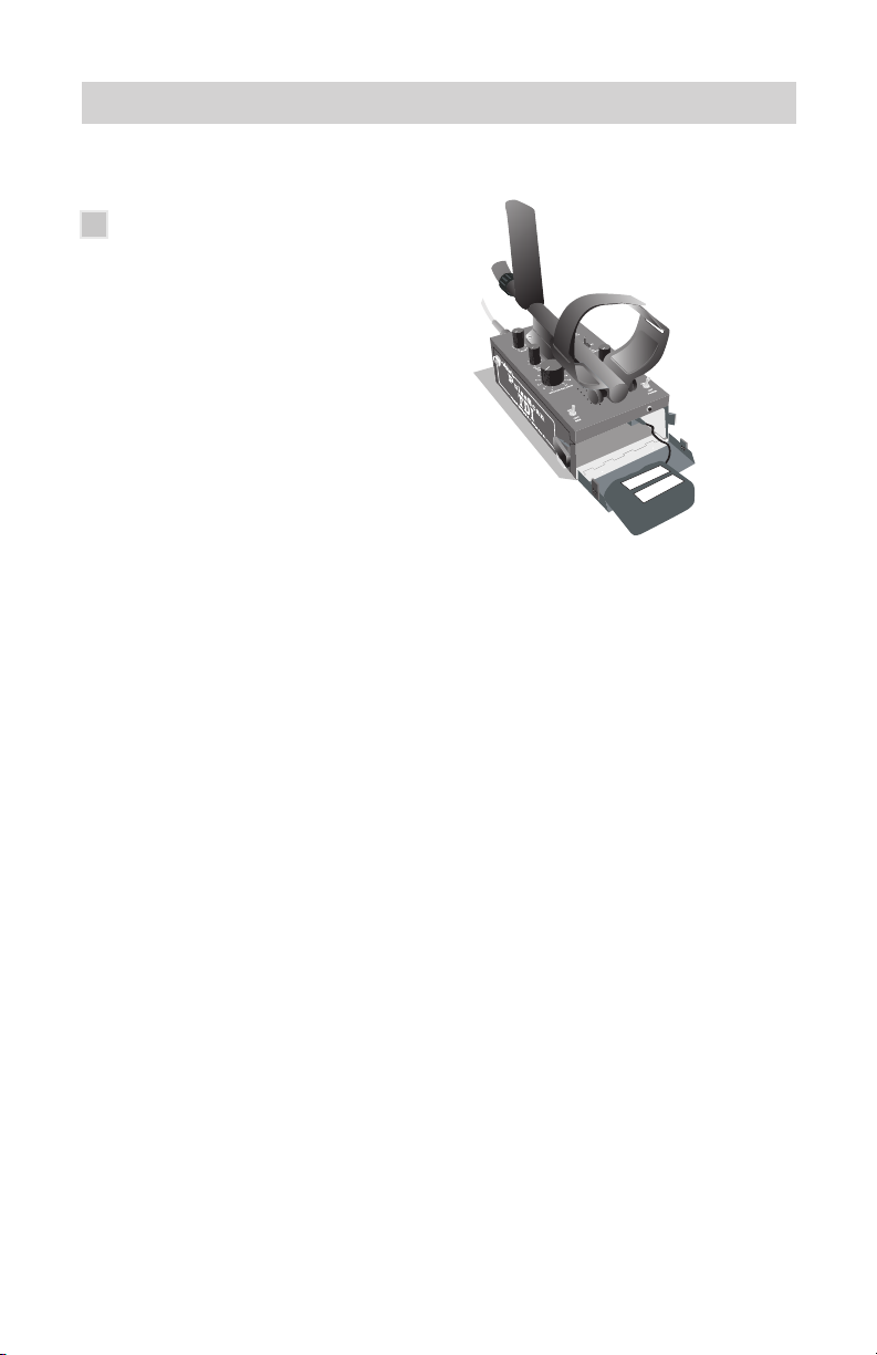
The Smart Charger (Part Number 509-0040) used for recharging the Lithium Ion
batteries is supplied with the detector. It has two internal lights that indicate the
status of the charge cycle.
TURN DETECTOR OFF,
AND RECHARGE
Page 9
PulseScan TDI Owner’s Guide 9
To recharge the battery:
1) Connect the battery pack to the charger and plug the
charger into the A.C. outlet.
2) The light in the charger will flash RED-GREEN-RED-
GREEN. This is a self check that indicates the charger is
operating correctly.
3) The RED light then comes on to indicate the battery is
charging.
4) When the battery reaches full charge, a minimum of seven
hours, the light will turn GREEN indicating that the battery is
ready to use.
5) If the battery is left connected the light will start to cycle
between RED and GREEN. Unplug the charger and dis connect the battery.
6) Only use the charger indoors. It is not weatherproof.
7) Do not cover the charger.
8) Do not use the charger in an ambient temperature greater
than 140 degrees Fahrenheit or 40 degrees Celsius.
9) Remove the charger from the AC outlet before
disconnecting battery.
10) Charger or battery may get very warm during charging.
This is normal.
If the battery has not been used for a long period of time, it is a good idea to
recharge before use in the detector.
Page 10
10 PulseScan TDI Owner’s Guide
CONTROLS
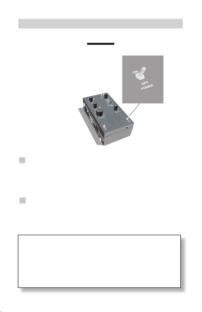
POWER -
What it does
This traditional control turns on or off the POWER from the internal, chargeable,
Lithium Ion battery pack. The toggle switch incorporates a locking device to
prevent accidental movement off or on.
How to use it
The locking mechanism prevents this toggle from accidentaly being bumped.
This is particularly valuable while operating the various control knobs. Just lift the
spring loaded toggle to release the lock and move the toggle.
IMPORTANT -
You must LIFT the Power Switch to release the lock, and move the
toggle.
Page 11
PulseScan TDI Owner’s Guide 11
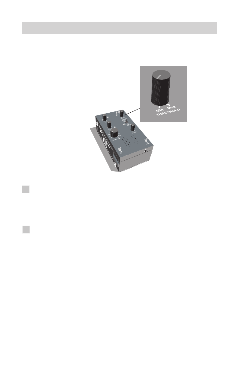
THRESHOLD -
What it does
This control adjusts the threshold of the unit. This is the faint background hum
which is present during the normal operation of the Pulsescan TDI. This hum,
which is always present, is increased when the knob is turned clockwise.
How to use it
In most detectors, including the Pulsescan TDI, the threshold is adjusted to a
faintly audible level by turning the knob clockwise. Unique to the Pulsescan TDI,
it is best to adjust the threshold past the chatter point, so that the sound is reasonably continuous. Then adjust the headphone volume to a comfortable level.
Page 12
12 PulseScan TDI Owner’s Guide
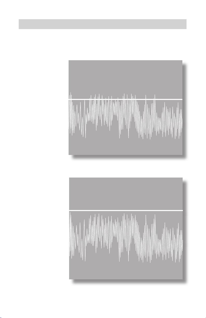
THRESHOLD LEVELS ...
NOT RECOMMENDED
Threshold
Level
Noise
Threshold
Level
Noise
➟
➟
Chatter can be heard in Threshold
IDEAL
➟
➟
Threshold set above chatter so chatter is not
heard. Reduce volume with headphones
Page 13
PulseScan TDI Owner’s Guide 13
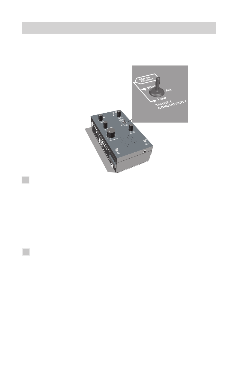
TARGET CONDUCTIVITY -
What it does
This control allows the user to select whether he wishes to hear only low-
conductive targets, only high-conductive targets, or both low and high conductive targets. Low-conductive targets, like small-to-medium sized gold nuggets
will make a high-tone sound. High-conductive targets like coins, except nickels,
will make a low-tone sound. This feature only works if the Gnd Bal toggle is in
the on position. When ground balance toggle is off, the switch must be set to All
or Low, and all signals will sound the same.
How to use it
Set to low for low-conductive metals only, including small to medium-sized
gold nuggets, most small to large specimen gold in quartz, small gold rings, very
small silver rings and small gold coins, nickels, small thin hammered silver coins,
small bronze Roman coins, small boot tacks, lead bird shot, tiny broken bits of
iron, aluminum pull tabs, foil and bits and tips of small nails, etc.
Set to high for high-conductive metalsonly, including all U.S.coins (except
nickels), most silver rings, silver U.S. coins, very large gold rings, large gold
nuggets, very high content gold nuggets (not common), U.S. gold coins above
2.5 dollars, 24 K gold bullion (e.g. Canadian Maple leaf), small to large nails
Page 14

14 PulseScan TDI Owner’s Guide
➟
ALL
Both
High and Low Conductivity Targets
RESPOND
➟
HIGH
Only
High Conductivity Targets
RESPOND
➟
LOW
Only
Low Conductivity Targets
RESPOND
Page 15

PulseScan TDI Owner’s Guide 15
when laying flat in the ground and large pieces of iron, large pieces of lead, lead
mini balls, lead musket balls, lead loom weights, bronze buckles, bronze weights,
bronze artifacts, etc.
NOTE: Mineralization, coil size, and ground balance settings can also
reverse the readings. Some low-conductive metals could make a low tone,
and/or some high-conductive metals could make a high tone. Set to ALL
for both high and low-conductive metals. As long as Gnd Bal is turned on,
both high and low tones wil be heard.
When prospecting for gold, it is possible to reject a large nugget when
selecting to only hear low-conductive metals. The size where a nugget can
be classified as large is not exact as its shape and configuration can also be
a factor. However, most all small-to-medium sized gold nuggets will fall in the
low-conductive category. Prospectors should possibly opt to search while
hearing both high and low-conductive metals until a determination is made
as to how targets, including trash, are responding. If the gold in the area
being searched is predominately small to medium sized, then searching in low
conductivity only will find most gold, and eliminate most iron trash.
Coin hunters can avoid digging pull tabs, foil and small bits of iron trash by using
high conductive only. Relic and beach hunters will ultimately find a way to make
use of this innovative feature. There is much to be learned by extensive field
use, but the possibilities appear to be endless.
MORE about Target Conductivity is listed under VARIABLE AUDIO on page
28 of this guide.
IMPORTANT -
The Conductivity Toggle only functions when the Ground Balance
Toggle is ON. If the Ground Balance Toggle is in the OFF position,
you must set the Conductivitiy Toggle to either ALL or LOW. If the
toggle is set to HIGH with Ground Balance OFF, there will be NO
SOUND on any target.
Page 16

16 PulseScan TDI Owner’s Guide
FREQUENCY -
What it does
This control makes small adjustments up or down to the transmitter pulse
frequency or rate. This is used to counteract any interference which might be
due to outside electromagnetic sources, such as radio stations, microwave, short
wave, electric fences, power lines, lightening, electrical storms, or other metal
detectors being used nearby. This interference is recognized by a warbling or
pulsing of the audio threshold in a repetitive way, and can mask target signals.
The Pulsescan TDI has a frequency range of 3.25 kHz to 3.37 kHz pulses per
second.
How to use it
Electrical interference is not exclusive to urban areas, where power line harmonics, local radio transmissions, or microwave transmissions can raise havoc with
the audio threshold. Getting too close to other metal detectors being operated
will also cause this problem. A slight adjustment of the frequency control can
help make the audio more stable.
Page 17

PulseScan TDI Owner’s Guide 17
PULSE DELAY -
What it is
The Pulsescan TDI transmits a pulse and then after a time delay, samples the
received signal. This is the control knob for adjusting the sample pulse delay. It
alters the time between the end of each transmitter pulse, and the start of the
receiver sampling period.
How to use it
PULSE DELAY is measured in micro seconds (uS). 10 uS is the lowest setting,
which samples as close as possible to end of the transmitter pulse. This setting
gives the highest sensitivity to all objects regardless of conductivity. However,
raising the pulse delay toward 25 uS is used to maximize the signal to highconductive metals such as silver or larger targets by supressing the signal from
low conductivity targets. This setting can be set anywhere between 10 uS and 25
uS depending on the circumstances to enhance performance.
If you wish to concentrate on detecting low-conductive targets you would
want to set your Pulse Delay as close to 10 uS as possible to avoid reducing or
losing the signal from your target. Low-conductive targets would include small to
Page 18

18 PulseScan TDI Owner’s Guide
medium gold nuggets, small or thin gold rings, and chains as well as very thin,
small hammered silver coins. If you were detecting for thin gold rings at a beach,
this would also be the proper setting to achieve the most sensitivity. Of course,
at 10 uS you will also hear small bits of iron trash, bits of foil, boot tacks and bits
of nails, and very small pieces of lead like bird shot. You may hear nails when
swept across the broadside, but not when sweeping from tip to tip. Aluminum
pulltabs will also be heard. Very low pulse delays can also result in the detection
of conductive salt water when detecting along beaches.
If you were primarily looking for high conductive metals, such as silver,
increase the Pulse Delay toward the maximum setting of 25 uSeconds,
thus reducing the signals from very small trash items such as small iron and foil.
Large iron usually falls into the category of silver, and gives a stronger signal at
higher pulse delays as well.
One important thing to remember is that whenever you change your Pulse Delay,
you should check and readjust your ground balance if necessary.
MORE about Pulse Delay is listed under PULSE DELAY on page 30 of this
Guide.
Page 19

PulseScan TDI Owner’s Guide 19
GAIN -
What it does
Gain controls the sensitivity of the detector, and the range at which the detector
will hear a given target. It increases or decreases the amplification of the receive
signal. In other words, it determines how deep the detector will hear a target.
How to use it
Ground mineralization gets in the way of hearing target signals. This so-called
bad ground can be balanced out by a ground balance procedure (a form of
filtering) so that targets can be heard clearly. This process can be accomplished
more easily and effectively if the gain is set at an appropriate level.
Never assume that the higher gain is set, the deeper the detector will go.
Although environmental noise EMI (electromagnetic interference) can affect the
level of gain that can be used, the ground mineralization has the most influence
on how high the gain can be set for optimum performance.
By attempting to use more gain than the ground minerals will allow, the detector circuit can go into overload, and at that setting will not be able to operate
properly. In this situation, reducing the gain will allow the detector to be ground
balanced, and thus operate correctly.
Page 20

20 PulseScan TDI Owner’s Guide
You must operate with a threshold which is as smooth as possible, so you can
hear the clarity of a true signal, and not be confused by false signals, chatter,
or blanking out of the threshold hum. Keeping the detector ground balanced is
important, but one of the best ways to keep a smooth operation is to apply the
appropriate amount of gain.
The threshold will let you know if the gain is set too high. If it is erratic, jumping
around, falsing, noisy, gasping - turn down the gain.
Page 21

PulseScan TDI Owner’s Guide 21
GROUND BALANCE ON/OFF - TOGGLE
What it does
The Toggle Switch, located below the Ground Balance knob, is used to either
enable or disable the ground balancing function (along with the Variable Audio
Tone feature). In the ON position, the Manual Ground Balance and the Audio
Tone feature are functional.
In the OFF position, the detector reverts to a straight pulse induction detector
which hears all metal targets without audio differentiation, and has no manual
ground balance control.
How to use it
This toggle must be kept in the On position when you are able to find a
ground balance point. In this instance, you have both Manual Ground
Balance and Audio Tone. If you can find a setting on the ground balance control
where the ground noises go away, then you must leave the Gnd BalToggle on,
and select a conductivity option. If you are not able to find a ground
balance point, and the detector operates quietly without interference no matter
where the control is set, it means that the ground is not mineralized enough to
require ground balancing. This means the Pulsescan TDI circuitry can handle
the ground without manual ground balancing, and the Gnd Bal toggle could be
turned off. In this case there are two options -
Page 22

22 PulseScan TDI Owner’s Guide
Option #1
You may switch the toggle to Off. This eliminates the Ground Balance control,
the Audio Tone feature, and the selectable conductivity feature allowing the
Pulsescan TDI circuitry to handle the ground mineralization. All targets will
sound alike, but you will get better depth.
Option #2
Switch the toggle to On. This activates the Ground Balance, and Audio Tone
feature. Then set the Ground Balance as noted in Chart A -
Chart A
Mandatory settings if you cannot find the ground balance point,
and wish to activate the variable Audio Feature.
#1 - If you have set the Pulse Delay at 10 uS, which is
recommended for average size gold, set the Ground Balance
control at approximately 8.
#2 - If you have set the Pulse Delay midway, set the Ground
Balance at approximately 6.
#3 - If you have set the Pulse Delay at 25 uS, which is
suggested for beaches, relics, or very large targets, set the
Ground Balance at approximately 2.
Page 23

PulseScan TDI Owner’s Guide 23
GROUND BALANCE - KNOB
What it does
This control adjusts or balances the interference from ground mineralization. It is
only operative when the Ground Balance toggle switch is in the On position.
How to use it
To ground balance Pulsescan TDI, the search coil is pumped slowly up and down
from one inch near the ground to 6 or 8 inches above the ground while listening
for a change in sound. This process must be done with the Target Conduc-
tivity control set to All.
Start this process with the Gnd Bal Control set at 6 (12 O’ clock). Begin pumping the coil slowly up and down toward the ground. You will hear the high tone of
low-conductive metal as you approach the ground. Now start turning the Ground
Balance knob slowly clockwise as you continue this pumping process. The high
tone will usually continue with each pump toward the ground for a short period of
time, and then start to fade to no tone other than the threshold hum. Continue
the process of pumping slowly, and turning the knob clockwise past the quiet
zone. You will begin to hear the low tone as you approach the ground. If the
ground has moderate mineralization you may not hear the low tone. At this point,
continue with the pumping process, but start to turn the ground balance knob
back counter clockwise until you enter the quiet zone again. This area of quiet
Page 24

24 PulseScan TDI Owner’s Guide
where you hear only the faint hum of the threshold is where the Pulsescan TDI is
balanced to the ground. You will have to turn the knob very slowly in very small
increments to reach the most exacting point for eliminating ground minerals. At
this point, you will most likely notice that the Ground Balance knob is usually
between 8 and 9 on the scale.
If you change the setting on the Gain or the Pulse Delay, you should adjust the
Ground Balance setting if needed. In addition, if you begin to hear ground noises
(false signals) you should also adjust the ground balance. Of course, the Gnd
Bal toggle must be On to use the Gnd Bal control.
If the Pulsescan TDI does not require ground balancing, there is another
option. The Pulsescan TDI can be operated as a standard pulse detector with no
variable audio by switching the Gnd Bal toggle OFF. All targets will now sound
the same. The upside of this is that the detector will detect deeper. Downside is
you dig everything.
If the Pulsescan does achieve ground balance, the Gnd Bal toggle must be
kept On, and both Gnd Bal and the Variable Audio feature will be active. This
situation indicates that there is enough iron mineralization to balance.
Page 25
INITIAL SET-UP -
PulseScan TDI Owner’s Guide 25
To get started, set the controls to a mid-range position. For now, the main concern is setting the threshold, and adjusting the settings for the other controls.
#1 - Set the controls to mid-range as follows -
Ground Balance 6
Conductivity All
Freq.Adj. 12 noon
(will only be active when Gnd.Bal.
toggle is ON)
(If there is interference
select a quiet frequency)
Pulse Delay 10 uS
Gain 6
Gnd.Bal. toggle OFF
Check your Battery LED for charge level
Page 26

26 PulseScan TDI Owner’s Guide
#2 - TURN ON AND ADJUST THRESHOLD
Turn the power switch On and adjust the threshold to a faint hum, as noted
under “Description of Controls”. The threshold hum should be set just above the
chatter point so that the hum is reasonably continuous - faint, but steady.
#3 - GET FAMILIAR WITH A TARGET SOUND
Put a target on the ground to become familiar with the response of the detector.
Use a nickel or a gold nugget. Please note that the Pulsescan TDI is a motion
detector which means that as the search coil passes over the target you hear a
response only when the search coil is kept in motion. Stopping over the target,
the signal will disappear and you only hear the threshold hum.
Be sure to use a reasonably sized target, so that you can get a better idea of
what a target sounds like. Note that the target audio will get louder, and the pitch
will rise as the search coil passes over the target. Now is a good time to adjust
the volume on the headphones so that you can hear a good response from the
target while being able to hear the continuous hum of the threshold when no
target is present.
Sweep the search coil from sideto-side overlapping each pass.
Keep the search coil at to the
ground as you are sweeping
from side-to-side.
Page 27

PulseScan TDI Owner’s Guide 27
#4 - DETERMINE IF GROUND BALANCE IS NECESSARY
At this point it is important to find out if there is enough mineralization in the
ground to require the Ground Balance control to be activated. Since in the
initial setting recommended above, the Gnd.Bal. toggle is set to off there is no
active ground balance, and the Pulsescan TDI has only its inherent ground
rejection ability working for it.
When the search coil is swept over the ground and there is no ground noise, (the
detector runs quietly and smoothly) then there is probably not enough ground to
balance. At this point you have two options as already described on Page 22.
a) You may leave the Gnd Bal toggle in the Off position and operate
the Pulsescan TDI with no Variable Audio as a straight pulse detector, and dig all
targets, or ...
b) If you wish to detect with Variable Audio active, you may switch the
Gnd Bal toggle to the On position and activate this capability, and set ground
balance according to Chart on page 22.
FINAL ADJUSTMENTS AND YOU ARE ON YOUR WAY
If all has gone well to this point, you might see if you can increase the Gain in
small stages. An increase in Gain is desirable in order to increase the depth of
detection. Never increase Gain at the expense of the inability to handle ground
minerals or environmental interference. As with the operation of all metal detectors, too much Gain will not increase but decrease depth, and the ability to hear
targets. It will be up to you to find the proper setting.
(With Gnd. Bal. Toggle OFF as on Chart A.)
If you change the Pulse Delay or the Gain, and you are operating with Gnd Bal
toggle on, you must readjust the Ground Balance.
Page 28

28 PulseScan TDI Owner’s Guide
MORE ON VARIABLE AUDIO (low/high tone)
Only if the Gnd Bal toggle is set in the on position will this Variable Audio feature
be active. You may then select the type of conductivity feature you wish to use.
Either low, high or both low and high. Dependability varies with the size, shape,
conductivity, and metal content of the target as well as the type of ground mineralization. In prospecting even the form of the gold (placer, sponge, crystalline
etc.) varies, and can make the ability to identify the target difficult as well.
When used for beach hunting and relic hunting, where the occurrence of certain
targets can be more predictable, the value of this feature might be more useful.
In any case the user should experiment in different locations or applications to
determine the level of predictability to be expected.
With some prospecting units on the market, this function is touted as an IRON ID
feature. This is not a true description of what is happening, and is why we will call
this feature Variable Audio, as that more correctly describes it. What is
really going on, is the audio responses heard are a by-product of the ground
balancing system, and are actually responding in a particular way to the speed at
which the signal from the target decays as the search coil passes over it.
Having tuned out the ground signal, the decay from metallic targets is either
faster or slower and does not balance out. Where it falls depends on its size,
shape, and conductivity not just whether it is gold or iron. Small to medium gold
and nickel coins (which decay faster) can react with a high-pitch tone, while large
gold, most silver and copper coins, and most iron (which decay slower) can react
with a low pitch. If you depend on this feature to always tell you that the target is
gold or iron, you could go wrong. Most smaller gold reacts in a predictable way,
but very large gold can react like iron. In addition, very small nails can react like a
small nugget.
The Variable Audio feature can be interpreted by the tone which it produces when
going over a target. As the search coil passes over a detected target, the signal
will get louder as it gets closer to the center of the coil, but the tone will rise or fall
depending on the decay speed.
Page 29

PulseScan TDI Owner’s Guide 29
Therefore, on a low-conductive target (small to medium gold, nickel coins, and
small iron) the pitch of the audio tone might rise.
When the search coil goes over a high-conductive target (large gold, most silver
and copper coins and most large iron) the pitch of the audio tone might fall.
It might be noted that the low tone heard over large non-iron targets is usually
smoother than the low tone heard over iron targets which can be irregular. In
addition, flat iron or steel objects, such as tin lids and flat sided cans can give
a mixed response. This can sound like low tone, high tone, low tone as coil
passes over the target. The sweep will have to be slower to notice this. The
high-tone response is usually stronger and longer, but with time and practice this
can be helpful to identify flat iron.
With practice, you will be better able to use your low tone and high tone to help
you get an idea of what kind of target you are detecting and help to eliminate
some trash items. However, it is always better in a new area to dig everything
until you get an idea of what you are likely to find. Keep in mind that no system
is perfect, and when in doubt DIG!
Page 30

30 PulseScan TDI Owner’s Guide
MORE ON PULSE DELAY
Sampling as close as possible to the end of the transmitted pulse gives the
highest sensitivity to all metal targets regardless of their content or conductivity.
The best signal from all targets is obtained when using a short (10 uS) delay.
However, increasing the Pulse Delay beyond 10 uS toward 25 uS will minimize
or eliminate the signal from low-conductive targets, so that high-conductors
stand out more even though they are giving out less of a signal because they are
sampled further down the decay curve. For maximum sensitivity to all targets, you
would want to set the Pulse Delay as close to 10 uS as possible. Thus, when
positioning the Conductivity Toggle at “ALL”, you will hear the familiar high tone if
the target is seen as low conductive, and the corresponding low tone if it is seen
as high conductive.
As you would expect, a nickel would fall into the same category as gold and will
be heard at 10 uS as a high tone, but larger silver and clad coins will produce
the low tone. With alloyed gold, the conductivity can vary, so the optimum pulse
delay can vary as well. Generally speaking, alloyed gold will be seen as low
conductive, so will be seen best at a lower pulse delay (10 uS ). 10k or 14k
rings will usually react as low conductive, whereas a purer gold ring, ( 22 k), may
react as high conductive . This can also be the case with very pure or large gold
coins and gold nuggets. A solid US $5, $10 or $20 gold coin will usually read as
high conductive, whereas, a $2 1/2 gold coin will read low conductive. Pure gold
Bullion (24k) like a one ounce Canadian Maple Leaf will read as high conductive
as well. This can be the case with a very large gold nugget or a very pure or high
gold content nugget, Fortunately, most gold nuggets are of mixed alloy and fall
into the low conductive category. Most U.S. gold nuggets readi as low conductive, thus producing the familiar high tone. However, most Alaska and Austrlian
gold which is over 90% gold will read as high conductive with a low sound.
The size and shape (surface area) of the target, not just the type or conductivity
of the metal, continues to have a bearing on the optimum setting for the Pulse
Delay. It would be a good idea to experiment with different targets at different
Pulse Delay settings. This is best done with the Ground Balance switched to
off, so that all targets sound the same, and the sensitivity to the target can be
observed. In this way, you can observe what happens to certain targets as the
Pulse Delay is advanced up from 10 uS. Setting pulse delays can be an important part of operating the Pulsescan TDI. After you have seen how the Pulse
Page 31

PulseScan TDI Owner’s Guide 31
Delay affects the signal, you can try the same tests with the Ground Balance
on and the Conductivity Toggle to all. At this time you can observe whether the
target produces a high tone or a low tone. You can then choose either the low
or high settings to observe how the Conductivity Toggle setting can eliminate or
accept a target.
The important thing is that you do have control over the Pulse Delay, and
therefore over the optimization of the sensitivity of the detector to certain desired
targets. The rule of thumb would be to set the Pulse Delay at 10 uS when
prospecting for small to moderate gold nuggets, and set it closer to 25 uS when
hunting on beaches for coins or relic hunting for iron and more conductive metals
such as brass.
Since the Pulse Delay setting does affect the Ground Balance process, you will
find that you have to ground balance after changing the level of pulse delay. In
addition, the level of pulse delay will have an affect on the ability to ground balance.
This was found out during our initial testing of the Pulsescan TDI on an extremely
black sand salt water beach. The Pulse Delay was initially set at 10 uS. At once,
we found that we had trouble achieving a clear ground balance point as the
extreme negative black sand and salt were too reactive. The audio was too
noisy to operate. Lowering the GAIN helped a little, but increasing the Pulse
Delay closer to mid-range (around 17.5 uS) rendered the threshold smooth, and
we achieved a clear ground balance point. Even though a Pulse Rate of 10 uS
would have been ideal for detecting for low conductive metals like gold, in this
instance, the higher pulse rate allowed for balancing the extreme black sand
which was our first concern. Even at the higher pulse rate, our first target was a
nickel coin over 12 inches, which has low conductivity just like gold.
Page 32

32 PulseScan TDI Owner’s Guide
WHITE’S WARRANTY
If within two years (24 months) from the original date of purchase, your White’s
detector fails due to defects in either material or workmanship, White’s will repair
or replace at its option, all necessary parts without charge for parts or labor.
Simply return the complete detector to the Dealer where you purchased it, or
to your nearest Authorized Service Center. The unit must be accompanied by a
detailed explanation of the symptoms of the failure. You must provide proof of
date-of-purchase before the unit is serviced.
This is a transferable manufacturer warranty, which covers the instrument two
years from the original purchase date, regardless of the owner.
Items excluded from the warranty are batteries, accessories that are not standard equipment, shipping/handling costs outside the continental USA, Special
Delivery costs (Air Freight, Next Day, 2nd Day, Packaging Services, etc.) and all
shipping/handling costs inside the continental USA 90 days after purchase.
White’s registers your purchase only if the Sales Registration Card is filled out
and returned to the factory address by your dealer soon after original purchase.
The purpose of recording this information is to keep you up-to-date regarding
White’s ongoing research & development.
The warranty does not cover damage caused by accident, misuse, neglect,
alterations, modifications, unauthorized service, or prolonged exposure to corrosive compounds, including salt.
Duration of any implied warranty (e.g., merchantability and fitness for a particular
purpose) shall not be longer than the stated warranty. Neither the manufacturer
or the retailer shall be liable for any incidental or consequential damages. Some
states however, do not allow the limitation on the length of implied warranties,
or the exclusion of incidental or consequential damages. Therefore, the above
limitations may not apply to you.
In addition, the stated warranty gives you specific legal rights, and you may have
other rights which vary from state to state.
Page 33

PulseScan TDI Owner’s Guide 33
The foregoing is the only warranty provided by White’s as the manufacturer of
your metal detector. Any “extended warranty” period beyond two years, which
may be provided by a Dealer or other third party on your detector, may be
without White’s authority, involvement and consent, and might not be honored by
White’s Electronics, Inc.
Page 34

34 PulseScan TDI Owner’s Guide
WHITE’S WARRANTY TRANSFER USA
If for any reason you should sell your Pulsescan TDI prior to the date the
warranty expires, the remaining warranty is transferable. This transfer is
authorized by calling 1-800-547-6911, and getting an Authorization Number.
Simply fill out the following information, including the Authorization
Number, seal it in a stamped envelope, and send it to White’s Electronics,
1011 Pleasant Valley Road, Sweet Home, Oregon 97386. The remaining
warranty period will then be available to the new owner.
The Warranty Statement applies to both the original owner as well as any
secondary owners.
WARRANTY TRANSFER
Original Owner -
Name: _________________________________________
Address: (Which appears on the original warranty card):
______________________________________________
________ ______________________________________
_______________________________________________
Imstrument Serial # ______________________________
Original Purchase Date:____________________________
NEW OWNER -
Name: _________________________________________
Address: ________________________________________
_______________________________________________
_______________________________________________
Comments: _____________________________________
_______________________________________________
✂
Page 35

PulseScan TDI Owner’s Guide 35
WHITE’S ELECTRONICS (UK) LTD.
After Sales Service - Limited Warranty
The serial number which is unique to your unit is on a white label inside
the battery compartment. Please quote this number on any correspondence regading your detector.
White’s Electronics has always been concerned with the absolute quality of their mineral/metal detectors. Service after the sales is of extreme
importance to us and we always do our utmost to ensure that customers
are satisfied with our units. If your unit should require servicing or repair,
simply return it to us at the factory in Inverness, and we shall carry out the
necessary work for you.
ANY WORK CARRIED OUT BY UNAUTHORIZED PERSONS WILL AUTOMATICALLY NULLIFY THE WARRANTY.
If within two years (24 months) from the original date of purchase, your
White’s detector fails due to defects in either material or workmanship,
White’s Electronics (UK) Ltd. will repair or replace at its option, all necessary parts without charge for parts or labor.
Simply return the detector to our factory in Inverness, Scotland, giving
details of the faults.
Items excluded from the warranty are non-rechargeable batteries and
other accessories.
The warranty is not valid unless the Warranty Registration Card is returned to the factory address within 10 days of the original purchase for
the purpose of recording that date, which is the actual commencement
date of the warranty.
Page 36

36 PulseScan TDI Owner’s Guide
WHITE’S WARRANTY TRANSFER UK
If for any reason you should sell your Pulsescan TDI prior to the date the
warranty expires, the remaining warranty is transferable.
Simply fill out the following information, including the Authorization Number, seal it in a stamped envelope, and send it to
White’s will then advise you what, if any Warranty is available.
The Warranty Statement must be completed with Serial number and
information on previous and new owners.
Original Owner -
Name: _________________________________________
Address: (Which appears on the original warranty card):
______________________________________________
________ ______________________________________
_______________________________________________
Imstrument Serial # ______________________________
Original Purchase Date:____________________________
White’s Electronics, (UK) Ltd.
35 Harbour Road
Inverness, Scotland, IV1 1UA.
WARRANTY TRANSFER
NEW OWNER -
Name: _________________________________________
Address: ________________________________________
_______________________________________________
_______________________________________________
Comments: _____________________________________
✂
Page 37

PulseScan TDI Owner’s Guide 37
This warranty does not cover damage to the detector caused by accident,
misuse, neglect, alterations, modifications or unauthorized service.
Duration of any implied warranties (e.g., merchantability and fitness for a
particular purpose) shall not be longer than the stated warranty.
Neither the manufacturer nor the retailer shall be liable for any incidental
or consequential damages resulting from defects or failures of the instrument to perform.
This warranty does not affect your statutory legal rights.
White’s Electronics (UK) ltd.
35 harbour Road - Inverness, Scotland - IV1 1UA
Telephone: (01463) 223456 - Fax: (01463) 224048
e-mail: sales@whelects.demon.co.uk.
Web site: www.whites.co.uk
Page 38

38 PulseScan TDI Owner’s Guide
WHITE’S WARRANTY SERVICE CENTERS
In the unlikely event your detector requires service please note our following Authorized Service Centers -
USA, ALL OF AMERICAS, PACIFIC RIM
1. Centerville Electronics
9859 Fairview Ave. Manassas, VA 20110
Toll Free: 888-645-0202, Or Toll: 703-367-7999
Fax: 703-367-0868 • E-Mail: bob@cwrelics.com
2. Electronic Exploration
575 West Harrison Lombard, IL 60148
Toll Free: 800-392-3223, Or Toll: 630-620-0618
Fax: 630-620-1005 • E-Mail: tony@ee-il.com
3. White’s Electronics, Inc.
1011 Pleasant Valley Road
Sweet Home, OR 97386
Toll: 541-367-6121 Extension 128
E-Mail: tmarshall@whiteselectronics.com
Web Site: www.whiteselectronics.com
Page 39

PulseScan TDI Owner’s Guide 39
UK, EUROPE, NORTHERN ASIA, AFRICA, NEAR EAST, MID EAST
White’s UK Ltd.
35J Harbour Road
Inverness, Scotland IV1 1UA
Telephone: (011)441-463-223-456
Fax: 441-463-224-048
E-Mail: sales@whelects.demon.co.uk
Web Site: www.whites.co.uk
Page 40

40 PulseScan TDI Owner’s Guide
40 PulseScan TDI Owner’s Guide
White’s Electronics, Inc.
1011 Pleasant Valley Road
Sweet Home, Oregon 97386 USA
541-367-6121
www.whiteselectronics.com
Jimmy “Sierra” Normandi
Part Number 621-0504
Edited by:
Mary Hand
Steve Howard
 Loading...