

Page 1

M6 Table of Contents
M6 Table of Contents
Chapter 1 Assembly...............................................................................2
Assembly Instructions .........................................................................................................................3
Chapter 2 Batteries.................................................................................4
Standard Battery Holder......................................................................................................................4
Using the Standard Battery Holder .....................................................................................................4
Rechargeable Battery (Opt.)................................................................................................................5
Battery Check ...................................................................................................................................... 5
Chapter 3 M6 Quick Start.................................................................. 6-7
Chapter 4 Display .. ............................................................................8-9
Chapter 5 Controls...............................................................................11
AUTO TRAC®...............................................................................................................................12-13
SENS (Sensitivity) ...................................................................................................................... 14-15
DISC (Discrimination) ................................................................................................................ 16-17
Chapter 6 Searching.............................................................................18
Pinpoint T echnique............................................................................................................................18
Headphones .......................................................................................................................................19
Field Use & Tuning Tips ............................................................................................................. 20-21
Chapter 7 Information..........................................................................22
Proper Care........................................................................................................................................22
Service ............................................................................................................................................... 23
Warranty ............................................................................................................................................ 24
Warranty Transfer..............................................................................................................................25
Owner Information ............................................................................................................................ 26
White's (UK)Ltd Warranty ................................................................................................................ 27
White's (UK)Ltd Warranty Transfer..................................................................................................28
1
Page 2
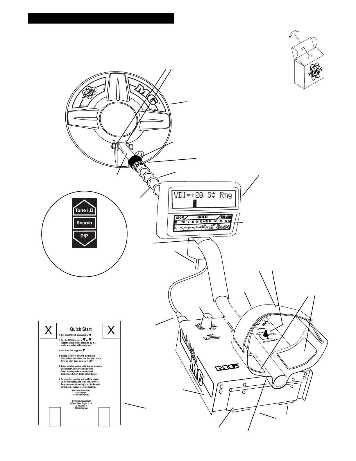
Chapter 1 M6 Assembly
Assembly
CLEVIS
LOWER
ROD
CENTER
ROD
WASHERS
BETWEEN
EACH LOOP
EAR & CLEVIS
LOOP OR SEARCH
COIL
CABLE RETAINER
CAMLOCK
LOOP CABLE
Twist and insert each end of
handle (provided) through top
of shipping carton into
second flap.
(CARRY CARTON)
DISPLAY
1/ VDI Numbers
2/ Target Identification
3/ Target Depth
4/ Pinpoint Location
5/ Battery Voltage
"S" ROD
Decal behind display shows
three functions/positions
of the TRIGGER
Remove decal paper from the two rubber
bumpers. Install on the bottom of the
control box, one in each of the front corners
(shown below by "X"). Press in place and
hold firmly for a few seconds then release.
LOOP
CONNECTOR
CONTROL BOX
TRIGGER
DISC
TARGET VDI
REFERENCE CHART
ELBOW
CUP
STRAP
ON/OFF
SENSITIVITY
TRAC
TOGGLE
ELBOW CUP
FOAM PADS
INSIDE ELBOW
CUP
2
BOTTOM OF
CONTROL BOX
BA TTERY
COMPARTMENT
DOOR
BA TTERY
COMPARTMENT
LATCHES
HEADPHONE
JACK
Page 3

Assembly Instructions
1. Remove all parts from shipping carton and
check the assembly page to make sure the kit is
complete.
Chapter 1 M6 Assembly
readjust clevis/lower rod length with the spring
clip buttons so that the search coil can be held near
the floor and remain standing comfortably.
2. There are rubber washers between clevis/lower
rod and loop ears. Use only the provided wash-
ers, fiber bolt, and thumbnut to secure loop/
search coil to clevis/lower rod.
3. Unlock rod camlocks and insert clevis/lower
rod into center rod. Center rod into curved "S" rod
so that stainless steel spring slip buttons line up
and lock into one of the adjustment holes. Turn
camlock to secure.
4. Unravel loop cable and wind the cable around
the clevis and rod assembly, first revolution over
the top of the rod. Wind cable all the way to the
top of the curved "S" rod, about five revolutions.
Use the black cable retainers, one near the loop,
and one behind the display, to hold the loop cable
in place. Plug loop connector into control box and
screw finger tight to secure.
5. Unlock control box rod camlock and insert
curved "S" rod so that stainless steel spring clip
buttons line up and lock into the rod on top of the
control box. The "S" rod is designed to curve up
toward the display. However, those who prefer to
sweep the loop close to their feet may desire to
assemble the "S" rod to curve down toward the
ground. Turn camlock to secure. Plug loop connector into control box, screw lock ring to secure.
7. Remove the protective paper from the two black
elbow cup foam pads. Carefully align pads on the
inside of the elbow cup, one on each side of the
center rod, and press firmly into place.
8. Adjust the elbow cup strap so that it is loose
enough for you to slide your arm in and out without loosening each time you want to set the detector down. The elbow cup strap provides extra
leverage and control, however, some prefer not to
use it.
9. Install battery as described in the next section, lid
decal facing down, with plastic tab and steel contacts
facing toward inside of battery compartment.
10. It should be noted at this point that the detector
may not work as expected indoors due to the high
degree of metals used in modern construction. It is
best to tune and practice outdoors to ensure stable,
predictable results. Additionally, freshly-buried
targets will not produce the normal depth and
discrimination results of targets that have been
naturally lost and settled in the ground. It may take
a number of years for freshly-buried targets to
respond at true depths and discriminate accurately.
The best way to determine true detection depth is
to use real search conditions.
6. Grip the instrument by the handle, with your arm in
the elbow cup with strap secure, and sweep the loop/
search coil over the floor. If the instrument fit feels
uncomfortable, adjust the elbow cup by removing
and repositioning the bolt/thumbnut and installing
in one of the optional positions. If necessary,
3
Page 4
Chapter 2 M6 Batteries
Batteries
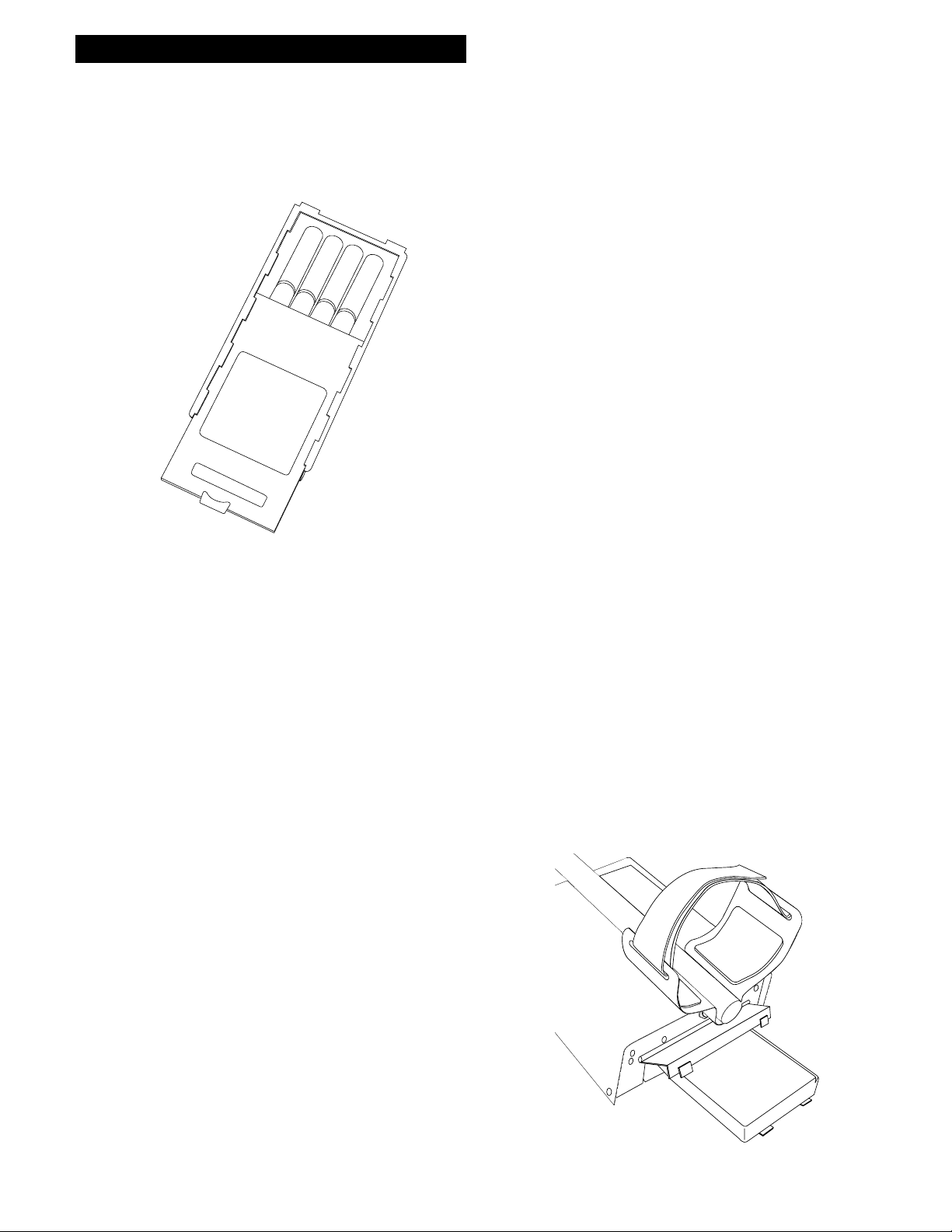
Battery Holder #802-7150
CAUTION
LIFT TAB AND PULL
Using the
Standard Battery Holder
1. Slide open the battery holder lid (decal side of
battery holder) by applying gentle upward
pressure on the tab of the door so that it unlocks.
Slide the door away from the battery box
exposing the cell positions.
2. Remove any old cells from the holder. Note the
(+) and (-) positions of each cell and the (+)
and (-) for each position marked inside the cell
tray. Install new “AA” cells noting carefully the
correct (+) and (-) positions.
Standard Battery Holder
1. The standard battery holder holds eight “AA”
cell batteries equalling 12 volts total. Alkalines are
recommended for use with this model. During
normal searching conditions you can expect about
40 hours of hunting time from a quality set of eight
alkaline batteries.
2. Non-alkaline batteries can be used in this holder.
When non-alkalines or rechargeable “AA”
cells are used, detecting time (before replacement/
recharge) may be reduced to about 30-35
hours.
3. The battery voltage appears automatically on the
display when the SENS knob is used to turn the M6
"ON". Once the batteries become weak (8 volts)
"Lo Bat" will automatically appear on the display
during searching. At that point the batteries should
be replaced. Alkalines provide some reserve time
after "Lo Bat" appears, rechargeables do not.
If the cells are installed incorrectly, the detector
may require service by an Authorized
Service Center.
3. Slide the door closed so that it snaps securely.
4. Insert the battery holder into the detector so that
the decal is facing down, with the battery
holder door tab and metal contact points facing
toward the inside of the battery compartment.
Close the battery compartment door and secure the
two latches on the bottom of the case. Hook the
front of each latch first, then press down on the
rear.
4. The battery compartment opens by gently
pulling down on the front of each of the two latches
(on the bottom of the control box) releasing the
catch and hinging open the door.
4
Page 5

Rechargeable Battery
(Optional)
A rechargeable battery system is not standard
equipment with your M6, however, high quality
systems are available.
White's rechargeable battery #802-5211, and
charger #509-0022 are recommended and offer
quick charge and overnight charge options.
Chapter 2 M6 Batteries
Non-rechargeable batteries will start to drop in
voltage as soon as they are put into use and then
steadily diminish in voltage until they die. The
Nicad rechargeable battery pack, however, will
diminish very slowly (plateau) somewhat steadily,
then drop quickly.
Headphone use prolongs all battery life.
Rechargeable batteries deliver fairly constant
voltage until they're nearly dead. If you use them
until they are dead, they will deteriorate more
quickly than if you only use them until their voltage
starts to drop significantly. Rechargeables should be
taken out of the detector and recharged as soon as
you notice "Lo Bat" on the display.
Rechargeable batteries will not provide the same
amount of continuous use as a new set of Alkaline
batteries.
CAUTION
Battery #802-5211
Battery life will vary a great deal with temperature,
number of target signals, battery type, brand, and
shelf life.
Alkaline Batteries may be used well into the "Lo
Bat" indication. Rechargeables can not.
Battery Packs are available (#802-7150). It is a
good idea to have a spare set when far away from a
new battery.
Charging
Hours
Using the Battery Charger on Quick Charge Setting
5
4.5
4
3.5
3
2.5
2
1.5
1
0.5
0
13 12 11.5 11 10.5 10 9.5 9 8.5 8 7.5 7 6.5 6
Battery Voltage Reading
Any voltage reading
less than 8 voltscharge for 5 hours
maximum on
Quick Charge
setting. Further
charging can
damage the
system.
5
Page 6
Chapter 3 M6 Quick Start
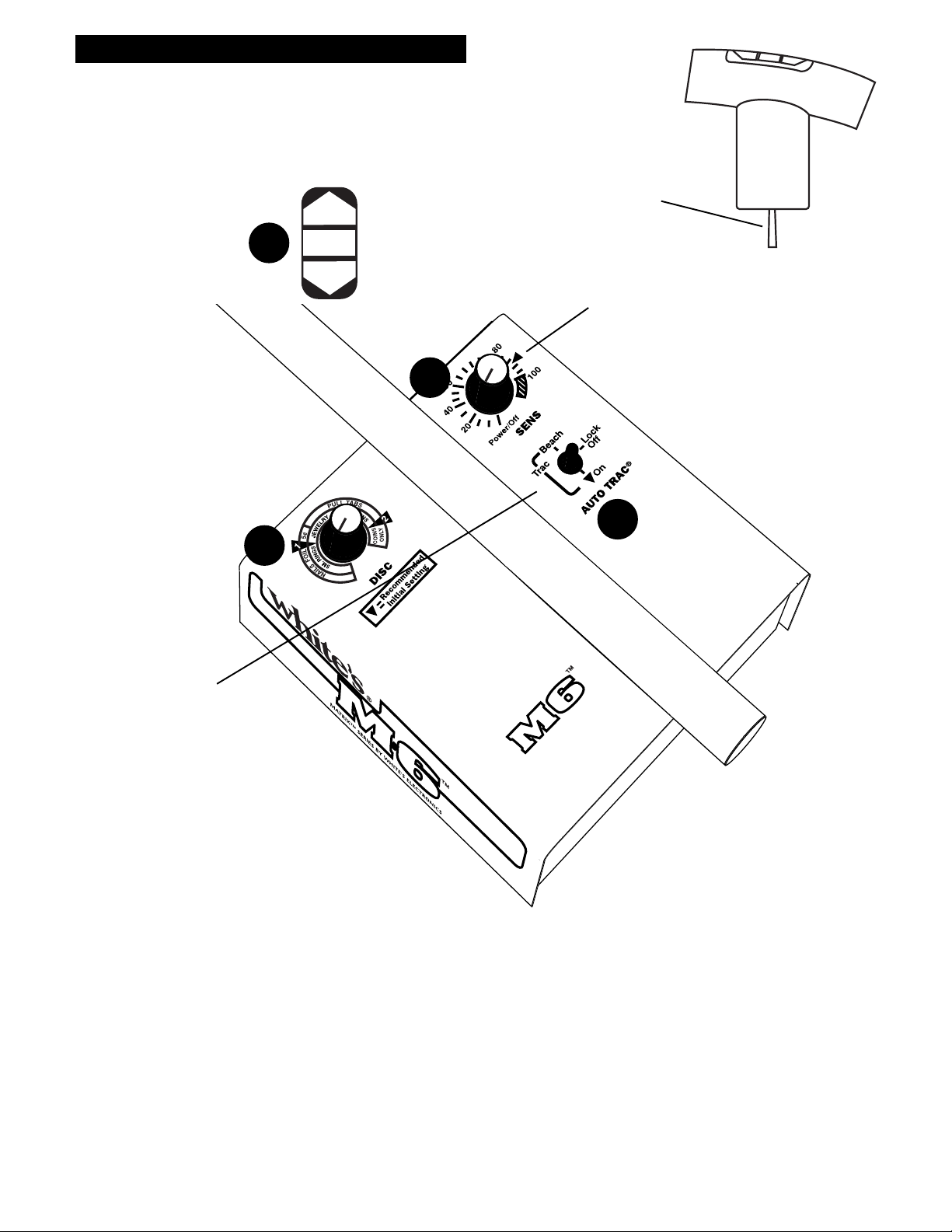
M6 Quick Start
2
DISC
establishes the level
of trash metal
rejection (Discrimination).
3
Tone I.D.
Search
P/P All Metal
Trigger Switch has three positions;
1. Forward (Tone I.D.).
2. Center (Search).
3. Squeezed and Held (Pinpoint/All Metal).
SENS
Turns the M6 ON/OFF and adjusts the
signal strength of targets, ground and
4
electrical interference.
1
TRAC Toggle
The Beach and "▼ On"
positions enable
"Auto Trac®" to adjust
automatically to beach and
ground conditions. The center
Off/Lock position locks the
tracking system and does not
track the ground.
6
Page 7
Quick Start
Instructions
With the M6 properly assembled and the
batteries installed, follow the instructions below to
start finding treasures!
Set the Auto Trac® Toggle to the
1
"On" position. "▼"
Set the Trigger Switch (under the hand
2
grip) to the center (Search) position.
Chapter 3 M6 Quick Start
* SPECIAL NOTICE* SPECIAL NOTICE
* SPECIAL NOTICE
* SPECIAL NOTICE* SPECIAL NOTICE
If you attempt to demonstrate or test the
M6 by waving targets in the air in front of
the search coil, the Auto Trac® toggle
must be in the Lock position.
Set DISC to " ".
3
Turn the SENS control clockwise until the
4
power clicks "ON". Rotate the SENS
control clockwise to "▼".
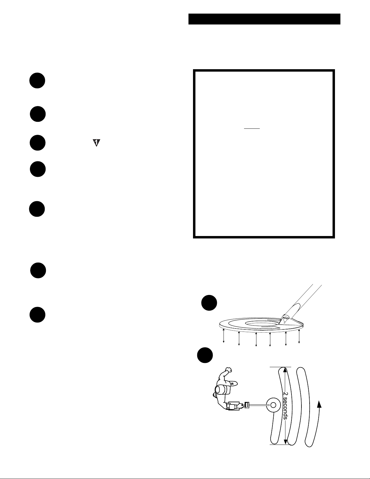
Lower the search coil to the ground, then
5
“pump” the coil up and down 2-4" a
couple of times and AutoTrac® will
automatically balance or track out the
ground mineralization.
Start swinging the search coil in wide
6
sweeps that overlap each other, as near
to the ground surface as possible, about one
second per foot.
If you experience false signals or constant
7
beeping or popping and you are not near
common sources of electrical interference,
set TRAC to LOCK and/or reduce SENS
(counterclockwise) slightly and try again.
When the M6 Auto Trac® toggle is in the
"On" or "Beach" positions with no
ground present, it will think that the
target IS ground and will attempt to track
it out.
You may, however, demonstrate the fast
ground balancing feature of Trac "On" or
"Beach" by waving or pumping a mineralized rock in the air in front of the search
coil.
5
2 to 4 inches
6
7
Page 8
Chapter 4 M6 Display
M6 Display
The M6 display and reference label below the
display provide a wealth of information about the
metal target. The display information works best
after the solid repeatable audio "beep".
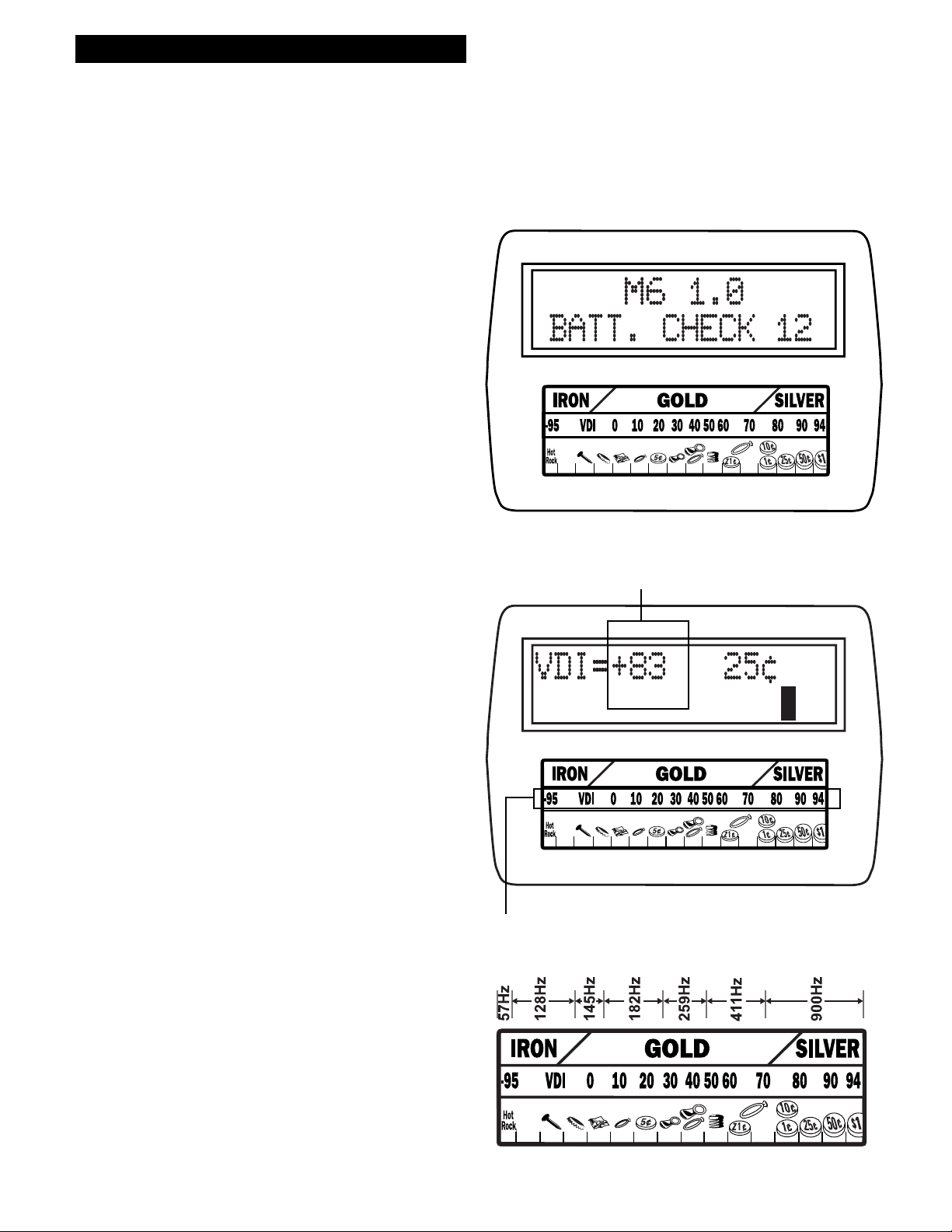
The display will momentarily show a software
version and battery voltage immediately after the
SENS knob is turned "on". The M6 operates on a
twelve volt battery system, new quality batteries
will indicate 12 + volts. After 35 to 40 hours of
operation,
"Lo Bat" will start appearing on the display at 8
volts and below. If using rechargeable batteries 8
volts is the end of their performance. If you are
using quality alkaline batteries you do have a small
reserve after 8 volts. Quality alkaline batteries will
provide extended normal performance well after the
"Lo Bat" warning.
VDI number on display
The M6 provides 5 different significant indications
on the display.
1. VDI = number - The VDI (Visual Discrimination Indication) is a reference number dictated
mostly by the metal targets exact alloy, size, and
shape. The reference label below the display provides a comparison of known targets and their
common VDI numbers. Different metal targets may
share the same VDI numbers based on their electrical characteristics. VDI numbers from -95 to +94
are available and cover the entire range of alloys
and sizes.
The M6 (hand grip toggle forward position) has
seven distinct tone ranges that correspond
directly to the types of targets indicated on the
display. The lower the tone, the lower the VDI
number.
VDI number range on reference label
8
Page 9

Half block indicates target I.D. is not certain.
Chapter 4 M6 Display
2. Blocks - A series of 16 blocks appear along the
bottom portion of the display and line up with the
indications on the reference label below the display.
It is important to note these blocks are from a
separate source than the VDI number and separate
sound provides a second opinion. A full block
indicates the M6 has complete information for
target identification. A half block indicates the M6
has partial information. A quarter block indicates
the M6 has only a small amount of target information.
3. Labels - The most common metal target (or
targets in some cases) within a particular Block is
listed on the display and referenced on the label
below the display. If two targets are listed, the first
to be listed is the most common, the second is less
common than the first.
Note: In this case, the 1¢ is the probable ID.
4. Depth Indication - Trigger (on hand grip)
squeezed and held, the display indicates the depth
of coin sized metals. Starting at 12 inches and
indicating in descending order (as the target gets
closer to the bottom of the search coil) the indicator
provides an aid in better locating the target in the
ground (how deep you will need to dig) and
whether the metal target is likely worth digging.
Only the heavier more valued targets get deeper
into undisturbed ground. Foil will not sink deeply
into undisturbed ground. Targets that indicate depth
readings from 3-5 inches are not as predictable.
5. PP Blocks - Trigger (on the hand grip) squeezed
and held, the PP blocks aid in pinpointing the exact
center of the metal target. When the search coil is
directly over the center of the metal target (longest
possible length PP Blocks) the depth reading is
giving you the most accurate depth indication. With
some experience the relative size and shape of the
metal target can be recognized during pinpointing.
NOTE: Please refer to page 18 for the proper "X"ing
technique to "Pinpoint the exact center of the target.
9
Page 10

10
Page 11

Controls
Chapter 5 M6 Controls
TriggerTrigger
Trigger
TriggerTrigger
Center Position (Discrimination) "Search"
The DISC control works like most traditional metal
detectors. Metal items below the DISC control
setting are rejected (quiet or broken) by the audio ...
metal items above the DISC control setting are
accepted and produce a smoother, solid, and more
consistent audio beep.
Forward Position "Tone I.D."
With the Trigger on the hand grip in the forward
position and DISC set at minimum, seven different
tones indicate the display categories from Iron
"Lowest Tone" thru Coins "Highest Tone". This
Tone I.D. feature makes the operator immediately
aware of the likely category of the metal item
without looking at the display. Each major Display
category has its own tone. Display categories
selected for rejection with the DISC control setting
either produce no beep at all or a broken, inconsistent beep. In addition, a very low tone and a display
reading of "OVERLOAD" appears when the search
loop is too close to a large metal item.
(on hand grip) (on hand grip)
(on hand grip)
(on hand grip) (on hand grip)
Tone I.D.
Search
Trigger control on
the hand grip
P/P
Squeezed and held "Pinpointing/Depth Reading". When the Trigger on the hand grip is
squeezed and held, the display indicates the depth,
in inches, of coin sized targets. Once released, the
trigger will automatically return to the Center
"Search" position.
11
Page 12

Chapter 5 M6 Controls
TRAC TOGGLE
Chapter 5 MXT Controls
AUTO TRAC® Toggle
The TRAC toggle selects the type of ground
mineral rejection (ground balance) and automatic
tracking to ground mineral changes best suited to
the specific area. Three different positions each for
a specific ground condition (ground type) are
provided.
The On position is used for normal or typical
ground conditions. In this position the M6 will
quickly compensate for ground minerals in a few
pumps of the search coil over the ground being
searched and quickly (automatically) track to any
ground changes as you sweep the search coil during
searching. For most operators, the On position will
be used for over 90% of your searching conditions.
The Lock position monitors, but does not track to
changing ground conditions. This position should
be used when decomposing iron or other unstable
ground conditions create noise and instability. This
"noise" appears when patches of ground are vastly
different from surrounding ground.
Find a "clean and quiet" area, pump the loop, and
move the toggle to the "Lock" position. Update
occasionally by moving the toggle to Beach or On
and repeat the above step.
12
Page 13

Chapter 5 MXT Controls
Chapter 5 M6 Controls
Eliminating Hot Rocks:
The "Lock" can be used to deal with rocks that
contain much different minerals than the surrounding ground. (Referred to as hot or cold rock). This
procedure is the reverse of the previous example. To
eliminate hot or cold rock, balance DIRECTLY
OVER the problem rock and move toggle to
"Lock". This eliminates the ground response of the
rock and detects targets only.
The Beach position provides an extended ground
balance and tracking range to compensate for salt
water beach and alkali. Ground rejection against
salt water and alkali slightly overlaps the lower end
of the conductive target (metal) range and may
produce a very slight reduction in sensitivity to
conductive targets. The advantage and performance
improvements of rejecting saltwater, however, far
outweigh any loss. The Beach TRAC is not recommended for normal conditions, only for saltwater
beaches and areas known to contain salt.
Summary - The On TRAC setting is recommended
for most searching conditions. Lock is used to hold
a ground rejection setting that is first established in
the On or Beach TRAC positions. Lock is recommended for areas that cause detector instability due
to extreme ground conditions such as a lot of
decomposing man made iron. Beach provides
extended ground rejection range to compensate for
conductive saltwater or alkali conditions.
Remember- When hunting in the "Beach" modebalance in the "Beach" mode.
13
Page 14

Chapter 5 M6 Controls
Chapter 5 MXT Controls
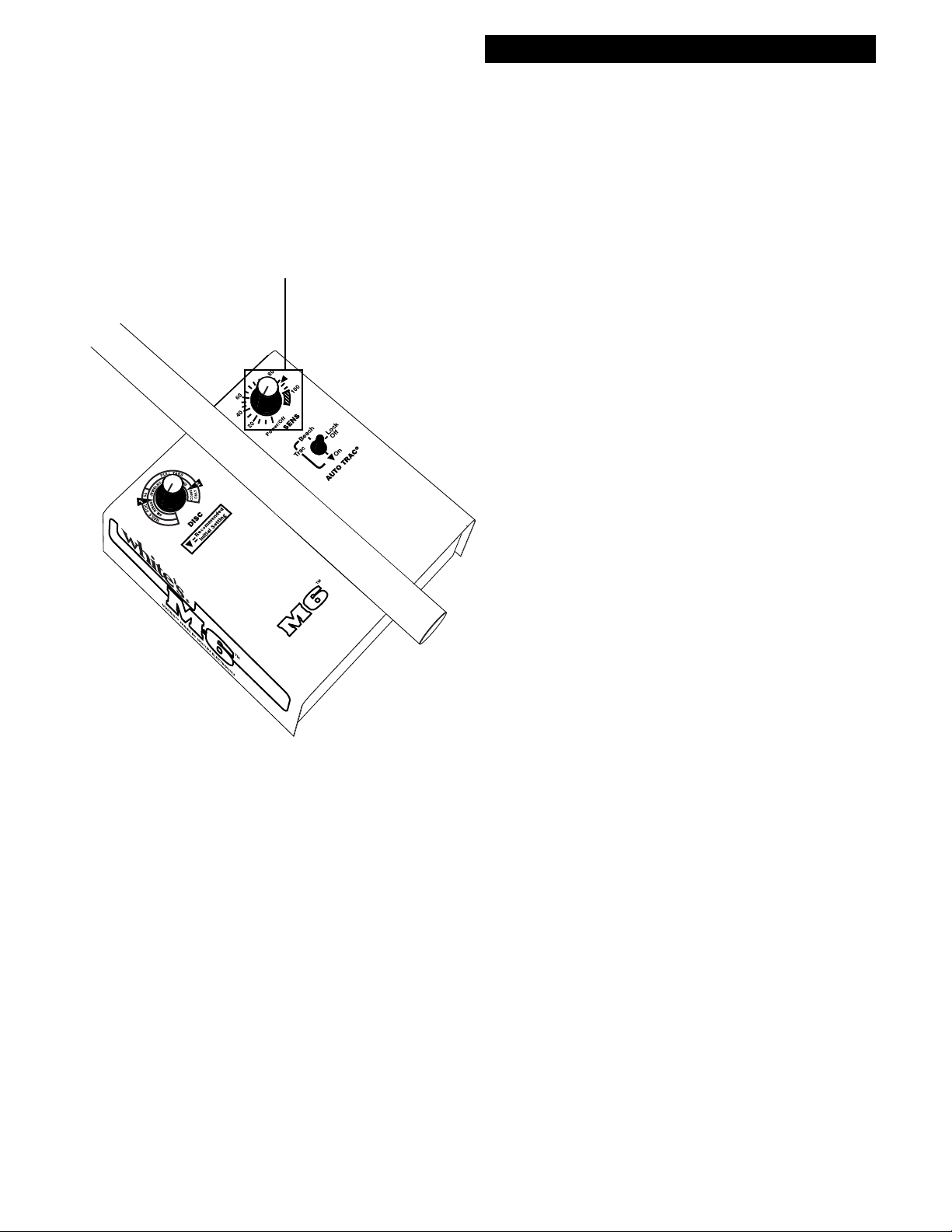
SENS Control
SENS Control/ON-OFF
The SENS control turns the instrument on/off and
selects the signal strength. Increased signal strength
does not always find more targets at greater depths.
Sometimes high ground mineralization will
"bounce" the signal back and mask good targets. It
is therefore necessary to ADJUST the SENS to give
you the maximum allowable SENS without masking targets or overloading
When ground mineralization is too high for the
SENS control setting, the display indicates
"OVERLOAD-REDUCE SENS/LIFT LOOP"
along with an audible "squawk". Reduce the SENS
until the overload warning ceases. On occasion,
while searching, you might sweep the loop over a
very large or very shallow target. The message on
the LCD display will read "OVERLOAD-RE-
DUCE SENS/LIFT LOOP". Sweep the loop a
little higher over the area and note the display and
audio indications. The M6 will self correct after the
message and you can continue to search as normal.
NOTE: Ground Mineralization too high, large or shallow target
message.
14
SENS Adjustment
1. The SENS control knob turns the M6 ON and
OFF and controls the SENS. Starting from the
POWER OFF position and going clockwise, the
power is turned ON and the dial increases the SENS
from a minimum level of 1 to a maximum level of
100+. Set the control to the "Initial Setting Triangle" ( between level 90 & 100 ).
2. Although the setting of 90-100 gives more than
enough SENS, if the ground mineralization is low
enough, you might attempt to raise the SENS above
100.
Page 15
Chapter 5 MXT Controls
Chapter 5 M6 Controls
SENS Adjustment (contin-
SENS Control
SENS Adjustment
(continued)
If, of course, "OVERLOAD-REDUCE SENS/
LIFT LOOP" message is displayed, common for
very nasty ground mineralization, you must heed it
and reduce the SENS rather than raise it.
3. If the ground is highly mineralized, SENS settings well below this initial triangle may be necessary to identify metal items, and will still provide
ample detection depth.
ued)
5. While using a steady slow search coil sweep
speed, simultaneously advance SENS towards
"100". If the "OVERLOAD-REDUCE SENS/
LIFT LOOP" alert keeps popping up on the
display, or if ground noises make it difficult to
recognize metal targets, reduce SENS counterclockwise.
6. The trash I.D. capability of the M6 also functions more accurately when the SENS is set at a
level which allows for smooth operation. Too
much SENS can cause bad ground to distort the
proper identification of iron and non-iron targets.
7. Note: It is normal to hear changes, clicks or soft
beeps, coming from the audio (speaker) during
SENS adjustments as the circuit shifts between
hardware and software SENS (different electrical
parts of the circuitry). The SENS control adjusts
both the hardware SENS (physical component) as
well as the software SENS (computer code) alternating between the two throughout it's range. As
the M6 shifts between these two intricate parts of
the circuitry an audio indication notes the transitions. This can be helpful. If you adjust the SENS
slightly, the audio notes a significant rather than
slight change.
8. The M6 provides more SENS control range than
is typically useful. Few areas will allow maximum
SENS (full clockwise) without at least some noisy
operation. Settings in the 100+ area require a high
degree of operator skill and patience.
4. In addition, any increase in SENS adjustment
should NOT BE at the expense of maintaining
predictable results without false signals, beeps and
static from bits of mineralization (erratic behavior).
15
Page 16
Chapter 5 M6 Controls
DISC CONTROL
Chapter 5 MXT Controls
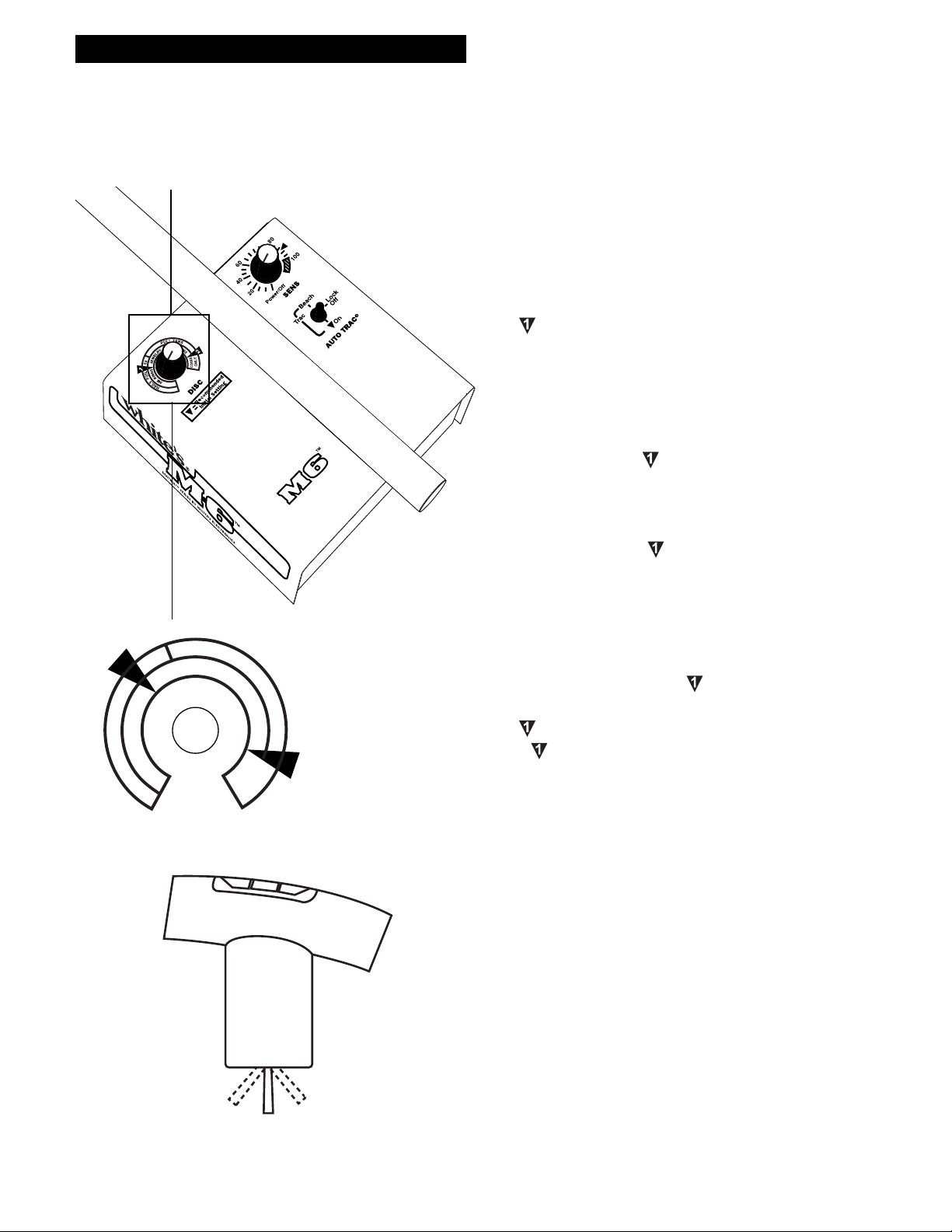
DISC (Discrimination)
Control
DISC (Discrimination) is used to adjust the level of
audio rejection against trash metals.
The (Preset) just below NICKEL is recommended for most general purpose searching. In this
position, the detector will provide a reject response
to most iron and small foil and respond to most
valuables including jewelry.
Positions lower than (counterclockwise)
provide less trash metal rejection, to the point of
detecting virtually all types of common metals.
Positions higher than (clockwise) will reject
more trash metals including aluminum pull tabs.
The display will continue to indicate I.D. even
though the audio discriminator will signal with a
reject (suppressed or broken) sound. Nickels and
P
¢
5
1
L
I
O
F
S
L
I
A
N
E
W
E
J
S
G
N
I
R
.
M
S
U
L
R
L
L
Y
R
T
I
N
A
G
B
S
S
C
O
I
N
S
S
2
N
I
Y
L
O
C
N
O
some jewelry will also be rejected with DISC
settings much greater than .
The position is recommended. If, when searching
at the position, you feel you are digging too
much trash, adjust DISC slightly clockwise and try
again. Finding the lowest (furthest counterclockwise) position that eliminates the common trash
metals in your area is important in order to find
items of jewelry.
The M6 provides two significantly different DISC
(Discrimination) modes.
1. Traditional DISC
Trigger
control on
the hand
grip
Put the Trigger on the hand grip in the center
position. When a trash metal is being rejected it will
produce no beep at all or a suppressed beep that is
shorter sounding typically inconsistent, a click or
DISC
flutter-sounding beep. When a valuable metal is
accepted it will produce a consistent, smooth, solid,
and longer sounding beep.
16
Page 17

Chapter 5 MXT Controls
Some large trash metals, such as pieces of lead, pot
metal, aluminum, tin, brass, copper, or significant
grade iron will produce a good sound regardless of
the DISC control position. An operator should dig
these unusual scrap metals to be successful.
2. Tone I.D.
With the Trigger on the hand grip in the forward
position, and the DISC control set at any typical
rejection level, Tone I.D. is available. Iron, if
accepted by the DISC control setting, produces the
lowest pitched beep. Coin range targets (pennies
and above) produce the highest pitch beep. Seven
different pitch beeps are available for each major
display category. Beep pitch is dictated by where
that specific item indicates on the display. Some
search coil motion is required to achieve detection
and T one I.D.
Trigger
control on
the hand
grip
Tone I.D.
Forward
Position
Chapter 5 M6 Controls
The loop must be in motion for metals to respond
and provide accurate discrimination. Each pass of
the loop from left to right (or from right to left)
should overlap the last by at least 50% and take
about two seconds.
NOTE* THE VISUAL I.D. SYSTEM IS OPERATING IN BOTH TOGGLE POSITIONS.
.
Find an outdoor area relatively free of metal to
practice. Place a coin on the ground. Pass the loop
over the coin. Note that some loop movement is
necessary to receive a good clean sound. Note that
if you sweep the loop too slow the coin doesn’t
respond well.
17
Page 18
Chapter 6 M6 Searching
Pinpointing
NOTE: Turn the detector 90° to the first side to side loop
movement and repeat for "X"ing the
center.
Chapter 5 MXT Controls
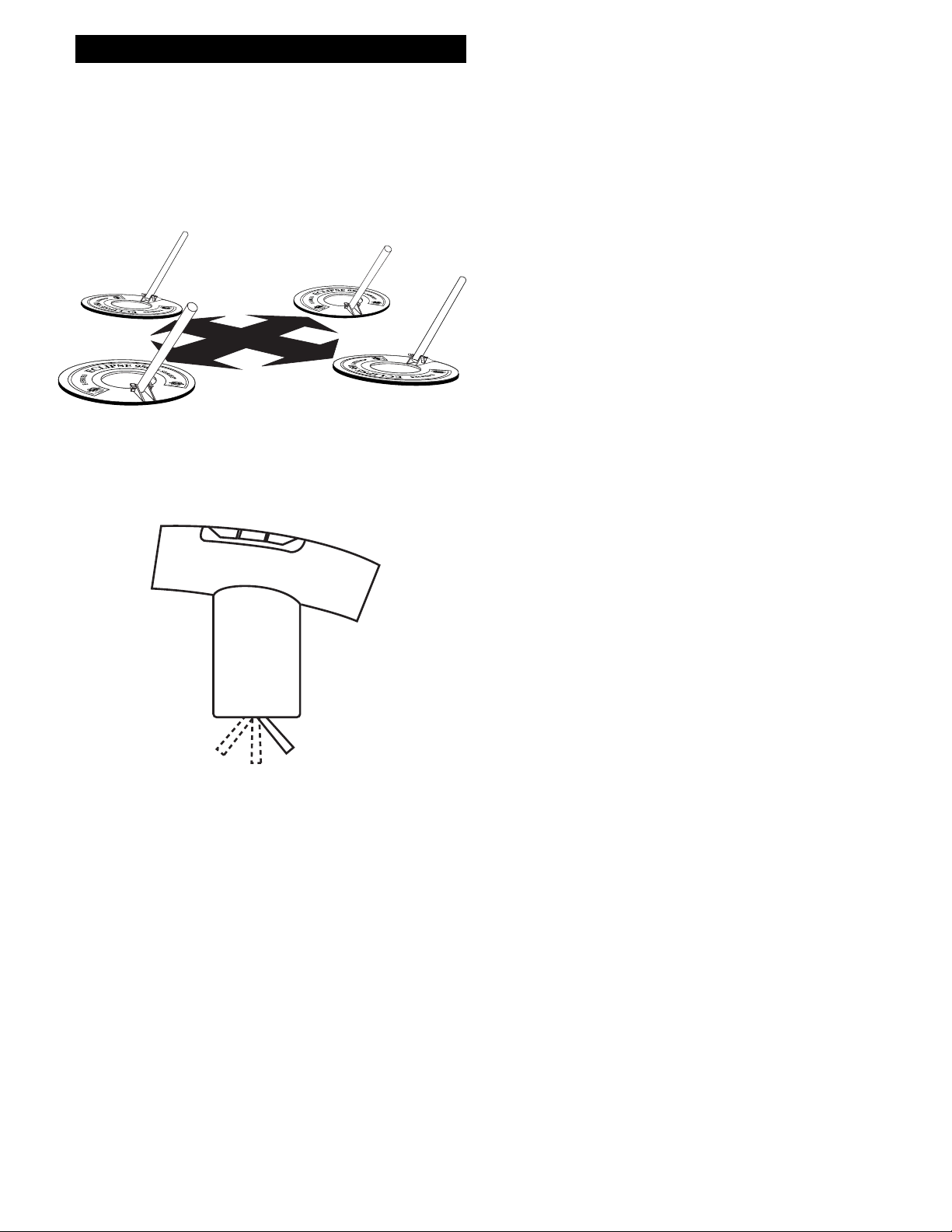
Pinpoint Technique
Due to the wide scan nature of modern search coils
it can be difficult to locate small targets under the
physical center of the loop. Use an "X marks the
spot" technique as shown in the diagram to identify
the portion of ground the metal target is in.
Squeezing and holding in the trigger on the grip
accesses a pinpoint and depth reading mode that
makes it much easier to sweep the search coil
slowly and center directly above the target. Use
loudest tone, display depth reading and bars, to
indicate targets exact center.
Again, the procedure is to sweep over the target
from side to side noting the side to side center. Then
turn 90 degrees and sweep the coil side to side
noting the center from this new direction. "X"
Trigger control
on the hand grip
Pinpoint
Squeeze and hold
trigger
marks the spot that you need to dig. You can practice with a coin on top of the ground to become
acquainted with this technique.
Shallow targets, 0-3" depth readings, are more
difficult to pinpoint than deeper targets. When
shallow depth readings are noted, lift the loop
several inches higher above the area, then X to
pinpoint.
18
Page 19
Chapter 5 MXT Controls
Chapter 6 M6 Searching
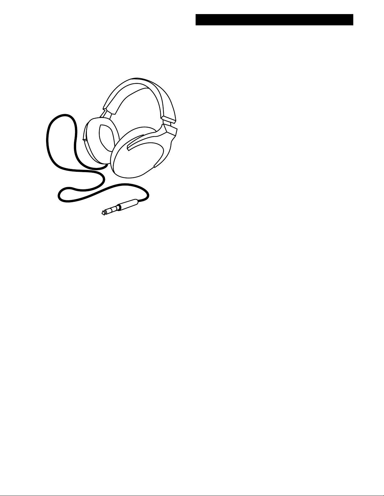
Headphones
The headphone jack on the M6 is located on the
control box above the battery compartment. There
is a dust cover on the headphone jack that needs to
be removed before the stereo plug from the headphone is inserted. Replace it when headphones are
not being used. Most users prefer high quality
stereo headphones so White's has chosen to wire
the headphone jack for stereo. If you have a mono
headphone, you can purchase an adapter that will
allow sound in both earpieces. Some headphones
come with a switch for stereo or mono jacks.
In choosing headphones, make sure they have a
VOLUME CONTROL as there is no target volume control on the M6. As well as comfort,
headphones also avoid bothering others with a
"beeping" box, and save on battery life. Many high
quality headphones from full ear enclosure to
lightweight summer models offering more safety
in snake and bear country are available on the
market. Higher impedance headphones (60 Ohms
or greater) give the most sensitivity. Properly
balanced impedance is important as well as low
distortion.
Whites has several headphone models to choose
from.
19
Page 20

Chapter 6 M6 Searching
Field Use & Tuning Tips
Chapter 6 MXT Searching
8. Once a solid repeatable beep is located
A. Push the Trigger forward and sweep the
search coil over the target area.
1. If it beeps with a high pitch tone
it is likely a coin worth digging,
proceed with 2.
1. Trigger (on hand grip) center " Search" position.
2. TRAC to On position.
3. SENS to "▼" position.
4. DISC CONTROL to DISC " ".
5. Pump the search coil on the ground to be
searched until ground ceases to respond.
6. Move the coil just over the ground and listen for
the distinct repeatable beep produced by a good
metal target. It is wise to plant metals just under the
soil to practice on in order to learn to recognize
what it will sound like. Planting a metal target
disturbs the ground mineral, which usually reduces
the depth it would have been found in undisturbed
ground. It will take practice to determine the proper
search speed and technique. Do not go too fast. Try
to overlap your sweep path so that you won't miss
the small and/or deeper metal targets.
a. If it beeps with a medium
pitch tone it is in the Pull Tab
range, Squeeze and hold the
Trigger on the hand grip and
check the depth. If it is
shallow (0 - 2 inches) depending on the hardness of
the ground, it is most likely a
Pull Tab and should be
ignored. If it is deeper
(beyond 2 inches) depending
upon the hardness of the
ground, it is likely heavier
gold jewelry and should be
dug.
2. Consult the display information.
3. Squeeze and hold the Trigger on
the hand grip and "X" the area to
pinpoint and note how deep you will
need to dig listed on the display.
7. Once a solid repeatable beep is located:
A. Consult the display information.
B. Squeeze and hold the Trigger on the
hand grip and "X" the area to pinpoint and
note how deep you will need to dig listed on
the display.
OPTIONAL method for Pull Tab/Jewelry
separation:
20
9. Heavy Pull Tab. In areas littered with hundreds
of Pull Tabs it may be necessary to search full time
in Tone I.D. or with the " " DISC setting and save
your time and efforts digging coins and jewelry that
indicate outside the pull tab range.
10. Ground Mineralization:
A. For Salt/Alkali environments proceed
exactly as above only with the TRAC toggle
in the Beach position.
B. For areas with an abundance of
decomposed man made iron (which may
make the M6 appear unstable only during
search coil sweeps), proceed exactly as
above only once you pump the loop over the
ground, then set the Trac control to Lock.
Page 21

Chapter 6 MXT Searching
Chapter 6 M6 Searching
The M6 provides good general purpose searching
for a wide variety of targets and environments.
From residential yards, parks and school grounds,
farm fields to beaches (for salt beaches use Beach
Trac setting).
Coins & Jewelry are the primary goals, however,
these settings and features will also respond to any
better alloy including common relics and any other
item made of a valued metal alloy.
The 1st choice a user should consider is the selection of an appropriate TRAC toggle setting for the
area. The On setting and Beach settings should be
almost self explanatory. If you are searching in
typical ground, use the TRAC On setting. If you are
on a salt water beach or desert alkali, use the TRAC
Beach setting. When to use the Lock setting can be
less obvious. If it seems like something is wrong
with the detector, wildly fluctuating (only while
sweeping the search coil), try the TracLock setting.
If the detector smooths out and starts operating
more predictably, you made the correct choice. If
there isn't any improvement, you may need to either
reduce the SENS control setting counterclockwise
and/or increase the DISC control setting clockwise.
An area littered with man made iron would dictate
the Lock setting. On the other hand an area littered
with small aluminum foil would not, such an area
would dictate the Reduced SENS and/or higher
discrimination settings.
The 2nd choice is SENS. Some areas require, and
some operators just prefer the more predictable
operation reduced SENS settings provide, where as
others prefer to push SENS to the limits of their
patience to find the deepest targets. There is a point
of diminishing returns either indicated by the
display indciating OVERLOAD, or a user missing
targets because they can not sort them out from
sporadic noises experienced at too high of a SEN
control setting.
The 3rd choice is the alternate MODE "Tone I.D."
accessed by pushing the Trigger (on the hand grip)
forward. Many prefer, after locating a target in the
primary Trigger center position, to check targets
with the Tone I.D. Others use the Tone I.D. as their
primary search mode. It depends a lot on the area
and degree of aluminum Pull Tabs present. Remember, the display will indicate if a metal target is in
the Pull Tab range in either Trigger position. Also
remember a metal target that indicates in the Pull
Tab range however, provides a deep depth indication, is more likely to be jewelry than a Pull Tab.
There are three types of targets that typically indicate in the Pull Tab range, Aluminum, Lead, Brass,
and Gold. Without consistency in size/shape, all a
metal detector can tell you is that it indicates within
that range of targets. It is up to the operator to
identify the common trash items of each area and
then weigh the likelihood of good targets.
The 4th choice is the level of audio Discrimination.
The " " setting provides a popular setting rejecting
most iron and small foil and accepting nickels and
most jewelry. Remember you have the display to
further sort out accepted metals. However, if the
common trash of the area consistently produces an
audio to the point of distracting from finding anything at all, an operator can increase discrimination
(clockwise) and check the area for silver and
copper. If a hot spot of multiple coins is located an
operator may then want to search isolated spots
within that area at lower discrimination settings.
Even with modern discriminating metal detectors, it
takes a good deal of patience to search high trash
areas.
.
21
Page 22

Chapter 7 M6 Information
Information
Proper care
I. Cleaning
Chapter 7 MXT Information
III. Storage
A. Both the coil and rod are waterproof and can
be cleaned with fresh water and mild soap. The
control box is not water proof and must be kept
dry. Never lift a wet coil above the height of
the control box as water can run down the
inside of the rod damaging the electronics. A
damp cotton cloth can be used to wipe off a
dirty control box.
II. Weather
A. Do not expose your detector to the condi-
tions of a car trunk during winter and/or summer extremes.
B. Protect it from direct sunlight during storage.
C. The control box is rain resistant, but
must be protected from heavy rain.
A. When the instrument is not in use, make sure
it is turned OFF.
B. If you plan on storing your detector for long,
remove the battery holder from the instrument
and remove the batteries from the holder.
C. Store the instrument indoors, in an area
where it will be protected from abuse. Over the
years White’s has noted more service repairs
and physical damage, on units in storage than
those experiencing daily use.
IV. Additional Precautions
A. Avoid dropping your detector while attempt-
ing to set it down to dig.
B. Avoid using your detector for leverage when
standing up from a dig.
22
C. Do not use any lubricants, such as WD-40®,
on any part of your detector.
D. Do not modify your instrument during its
warranty period.
Page 23

Chapter 7 MXT Information
Chapter 7 M6 Information
Service
White’s reputation has been built on quality products backed by quality service. Our Factory Authorized
Service Centers are factory trained and equipped. They offer the same quality service as the factory.
Service before and after the sale is the cornerstone of our customer relations.
White’s Authorized USA Service Centers:
Centerville Electronics
10063 Wellington Road Road
Manassas, Virginia 20110
Toll Free 1-888-645-0202
Fax: 1-703-367-0868
E-Mail: centelec@vwx.com
Electronic Exploration
575 West Harrison
Lombard, Illinois 60148
Toll Free: 1-800-392-3223
Fax: 1-630-620-1005
E-Mail: tony@ee-il.com
White’s Electronics, Inc.
1011 Pleasant Valley Road
Sweet Home, Oregon 97386
Telephone: 1-541-367-6121
Fax: 1-541-367-6629
E-Mail: nbaker@whiteselectronics.com
Before shipping detectors for service:
A. Contact your Dealer. There may be a quick,
simple fix or explanation that will prevent
having to send the detector in for service.
B. Double check the obvious, such as batteries,
and try the detector in another area to be sure
there is not interference.
C. Be sure to send all necessary parts with your
detector such as search coil, batteries and
holders.
D. Always include a letter of explanation about
your concerns, even if you have talked to the
Service Center by telephone.
E. Take care in packaging instruments for
shipping and always insure your package.
23
Page 24

Chapter 7 M6 Information
Warranty
If within two years (24 months) from the original
date of purchase, your White's detector fails due to
defects in either material or workmanship, White's
will repair or replace at its option, all necessary
parts without charge for parts or labor.
Simply return the complete detector to the Dealer
where you purchased it, or to your nearest
Authorized Service Center. The unit must be
accompanied by a detailed explanation of the
symptoms of the failure. You must provide proof of
date-of-purchase before the unit is serviced.
This is a transferable manufacturer warranty, which
covers the instrument two years from the original
purchase date, regardless of the owner.
Items excluded from the warranty are nonrechargeable batteries, accessories that are not
standard equipment, shipping / handling costs
outside the continental USA, Special Delivery costs
(Air Freight, Next Day, 2nd Day, Packaging
Services, etc.) and all shipping / handling costs
inside the continental USA 90 days after purchase.
Chapter 7 MXT Information
Duration of any implied warranty
(e.g., merchantability and fitness for a particular
purpose) shall not be longer than the stated
warranty. Neither the manufacturer or the retailer
shall be liable for any incidental or consequential
damages. Some states however, do not allow the
limitation on the length of implied warranties, or
the exclusion of incidental or consequential
damages. Therefore, the above limitations may not
apply to you.
In addition, the stated warranty gives you specific
legal rights, and you may have other rights which
vary from state-to-state.
The foregoing is the only warranty provided by
White's as the manufacturer of your metal detector.
Any "extended warranty" period beyond two years,
which may be provided by a Dealer or other third
party on your detector, may be without White's
authority involvement and consent, and might not
be honored by White’s Electronics, Inc.
White's registers your purchase only if the Sales
Registration Card is filled out and returned to the
factory address by your dealer, soon after original
purchase for the purpose of recording this
information, and keeping you up-to-date regarding
White's ongoing research & development.
The warranty does not cover damage caused by
accident, misuse, neglect, alterations,
modifications, unauthorized service, or prolonged
exposure to corrosive compounds, including salt.
24
Page 25

Chapter 7 MXT Information
Warranty Transfer
If for any reason you should sell your White's detector prior to the date the warranty
expires, the remaining warranty is transferable. This transfer is authorized by calling 1-
800-547-6911, and getting an Authorization Number.
Simply fill out the following information, including the Authorization Number, seal it in a
stamped envelope, and send it to White's Electronics, 1011 Pleasant Valley Road, Sweet
Home, Oregon 97386. The remaining warranty period will then be available to the new
owner.
The Warranty Statement applies to both the original owner as well as the second owner.
Chapter 7 M6 Information
"
Original Owner:
New Owner:
WARRANTY TRANSFER
®
Name: __________________________________________________________
Address (Which appears on the original warranty card):
________________________________________________________________
________________________________________________________________
Instrument Serial Number: __________________________________________
Original Purchase Date:_____________________________________________
Name: __________________________________________________________
Address: ________________________________________________________
________________________________________________________________
________________________________________________________________
Comments: ______________________________________________________
________________________________________________________________
________________________________________________________________
________________________________________________________________
________________________________________________________________
Distributor Authorization Code: _______________________________________________
25
Page 26

Chapter 7 M6 Information
Chapter 7 MXT Information
Owner Information
Serial Number: __________________________ (inside of battery compartment)
Purchase Date: __________________________ (The date on the sales receipt)
Dealer Name: _____________________________________________________________________
Address: ___________________________________________________________________
Telephone #: ________________________________________________________________
Payment method: __________________________________________________________________
Personal markings: _________________________________________________________________
________________________________________________________________
26
Page 27

Chapter 7 M6 Information
WHITE'S ELECTRONICS (UK) Ltd.WHITE'S ELECTRONICS (UK) Ltd.
WHITE'S ELECTRONICS (UK) Ltd.
WHITE'S ELECTRONICS (UK) Ltd.WHITE'S ELECTRONICS (UK) Ltd.
After Sales ServiceAfter Sales Service
After Sales Service
After Sales ServiceAfter Sales Service
LIMITED WARRANTY STATEMENTLIMITED WARRANTY STATEMENT
LIMITED WARRANTY STATEMENT
LIMITED WARRANTY STATEMENTLIMITED WARRANTY STATEMENT
The Serial Number which is unique to your unit is on a White Label inside the Battery Compartment.
Please quote the number on all correspondence regarding your detector.
White's Electronics have always been concerned with the absolute quality of their metal detectors. Service after the sale is of
extreme importance to us and we always do our utmost to ensure that customers are satisfied with our units. If your unit should
require servicing or repair, simply return it to us at the factory in Inverness and we shall carry out the necessary work for you.
Any work carried out by unauthorized persons will automatically nullify the warranty.
If within 2 years (24 months) from the original date of purchase, your White's detector fails due to
defects in either material or workmanship, White's Electronics (UK) Ltd will repair or replace, at its
option, all necessary parts without charge for parts or labour.
Simply return the Control Box, Searchhead and, if used - rechargeable battery and charger to our factory in
Inverness giving details of the faults and contact details (Daytime telephone number if possible.) Items
excluded from the warranty are non-rechargeable batteries, and other accessories.
The warranty is not valid unless the Warranty Registration Card is returned to the factory address within
10 days of purchase fro the purpose of recording that date, which is the actual commencement date of the
warranty.
The warranty does not cover damage caused by accident, misuse, neglect, alterations, modifications or
unauthorized service.
Duration of any implied warranty (e.g.. Merchantability and fitness for a particular purpose) shall not be
longer than the stated warranty.
Neither the manufacturer nor the retailer shall be liable for any incidental or consequential damages
resulting from defects or failures of the instrument to perform.
This warranty does not affect your statutory legal rights.
White's Electronics (UK) Ltd
35 Harbour Road ~Inverness ~ Scotland ~ IV1 1UA
Telephone: (01463) 223456 Fax: (01463) 224048
Email: sales@whelects.demon.co.uk
Web site: www.whites.co.uk
27
Page 28

Chapter 7 M6 Information
WARRANTY TRANSFERWARRANTY TRANSFER
WARRANTY TRANSFER
WARRANTY TRANSFERWARRANTY TRANSFER
If for any reason you should sell your White's Metal Detector prior to the date the warranty
expires, the remaining warranty may be transferable.
Simply fill out the Warranty Transfer form below, send it to White's Electronics (UK) Ltd,
35 Harbour Road, Inverness, Scotland, IV1 1UA. White's will then advise you what, if any Warranty is available.
The Warranty Statement must be completed with Serial number and information on previous and new owners.
Original Owner:
Name: __________________________________________________________
Address (as on original Warranty Card):
________________________________________________________________
________________________________________________________________
Serial Number: (inside battery door)___________________________________
New Owner:
Name: __________________________________________________________
Address: ________________________________________________________
________________________________________________________________
________________________________________________________________
Tel: ______________________ Email: _____________________________
WARRANTY TRANSFER
(#621 - 0493 - 1) Printed in U.S.A. (11/2005)
28
 Loading...