


GOLDMASTER GMT

1
GMT Table of Contents
Chapter 1 Assembly...............................................................................2
Assembly Instructions .........................................................................................................................3
Chapter 2 Batteries.................................................................................4
Standard Battery Holder...................................................................................................................... 4
Using the
Standard Battery Holder................................................................................................................... 4
Rechargeable Battery(Opt.).................................................................................................................5
Battery Check ......................................................................................................................................5
Chapter 3 GMT Quick Start ..................................................................6
Quick Start
Instructions .......................................................................................................................................7
Chapter 4 Controls.................................................................................8
Gain Control/Power Off ......................................................................................................................8
Gain Adjustment..................................................................................................................................8
Gain Adjustment (cont'd) ....................................................................................................................9
Audio Signal Boost Toggle ...............................................................................................................10
Hot Rocks ..........................................................................................................................................11
Variable SAT Speed Control..............................................................................................................11
VSA T Adjustment..............................................................................................................................11
Iron I.D. Trigger Adjustment .............................................................................................................12
Threshold Control ............................................................................................................................. 13
Threshold Adjustment .......................................................................................................................13
Ground Balance
Fast AutoTrac ..................................................................................................................................14
Manual Ground Balance....................................................................................................................15
Ground Balance Adjustment .............................................................................................................15
Chapter 5 Searching.............................................................................16
Pinpoint T echnique............................................................................................................................16
Headphones ....................................................................................................................................... 17
Field Use & Tuning Tips ...................................................................................................................18
Field Use & Tuning Tips (cont'd)......................................................................................................20
Field Use & Tuning Tips (cont'd)......................................................................................................22
Chapter 6 Information..........................................................................24
Proper Care........................................................................................................................................24
Service ...............................................................................................................................................25
Warranty ............................................................................................................................................ 26
Warranty Transfer..............................................................................................................................27
Video and Owner Information...........................................................................................................28
GMT Table of Contents
NOTE: Due to Acrobat PDF limitations the Introductory page is on page 29
2
Assembly
Chapter 1 GMT Assembly
ELBOW
CUP
STRAP
ELBOW CUP
FOAM PADS
INSIDE ELBOW
CUP
CONTROL BOX
“S” ROD
LOOP CABLE
CAMLOCKS
WASHERS
BETWEEN
EACH LOOP
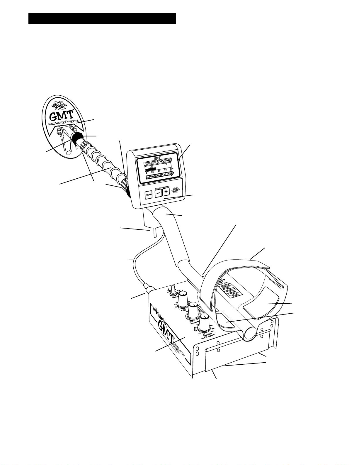
EAR & CLEVIS
METER / DISPLAY
1/ Iron I.D. % Probability Bar Graph
2/ Type of Minerallization ( 0 to 99 )
3/ Amount of Mineralization ( 0 to 99 )
4/ Battery Check Bar Graph or Message
5/ Overload Message
TOUCHPADS
1/ Grab
2/ Manual Gnd. Balance (-) (+)
AUDIO.
IRON I.D.
TOGGLE
CABLE RETAINERS
BA TTERY
COMPARTMENT
DOOR
BATTERY
COMPARTMENT
LATCHES
LOOP CONNECTOR
HEADPHONE JACK
CLEVIS
LOWER
ROD
CENTER ROD
SECTION

3
Chapter 1 GMT Assembly
5. Grip the instrument by the handle, with your
arm in the elbow cup with strap secure, and sweep
the coil over the floor. If the instrument fit feels
uncomfortable, adjust the elbow cup by removing
and repositioning the bolt/thumbnut and installing
in one of the optional positions. If necessary,
readjust clevis/lower rod length with the sping clip
buttons so that the searchcoil can be held near the
floor without requiring stooping over.
6. Adjust the elbow cup strap so that it is loose
enough for you to slide your arm in and out with-
out loosening each time you want to set the detec-
tor down. Peel and stick elbow cup foam pads on
the inside of the elbow cup, one on each side.
7. Install battery as described in the next section,
decal facing down, with plastic tab and steel
contacts facing toward inside of battery compart-
ment.
8 It should be noted at this point that the detector
may not work as expected indoors due to the high
degree of metals ( nails, pipes, etc.) used in modern
construction and the presence of electrical interfer-
ence. It is best to tune and practice out-of-doors to
ensure stable, predictable results.
Assembly Instructions
1. Remove all parts from shipping carton and
check the assembly page to make sure all parts are
present.
2. Unlock "S" rod camlock and insert the reduced
end of the center rod into curved "S" rod so that
stainless steel spring clip buttons line up and lock
into the holes in the curved "S" rod. Turn
camlock to secure.
3. Fit the rubber washers between clevis/lower
rod and searchcoil ears. Use only non-metallic
washers, fiber bolt, and thumbnut, to secure loop
to clevis/lower rod. Then insert into center rod so
that stainless steel spring buttons line up and lock
into one of the adjustment holes in the center rod.
Turn Camlock to secure.
4. Unravel cable and wind the cable around the
clevis and rod assembly, first revolution should be
OVER the top of the rod with some slack before
applying the cable retainer. This is done so that
the search coil can be paddled backwards toward
the rod without putting a strain on the cable.
Wind cable firmly all the way to the handle toggle
switch. Then plug connector into control box
turn lock ring to secure. To secure cable, wrap
velcro cable retainers around rod and cable, one
near the searchcoil and one near the toggle switch.
4
Batteries
Chapter 2 GMT Batteries
Using the
Standard Battery Holder
1. Slide open the battery holder lid (decal side of
battery holder) by applying gentle upward
pressure on the tab of the door so that it unlocks.
Slide the door away from the battery box
exposing the cell positions.
2. Remove any old cells from the holder. Note the
(+) and (-) positions of each cell and the (+)
and (-) for each position marked inside the cell
tray. Install new “AA” cells noting carefully the
correct (+) and (-) positions.
If the cells are installed incorrectly, the detector
may require service by an Authorized
Service Center.
3. Slide the door closed so that it snaps securely.
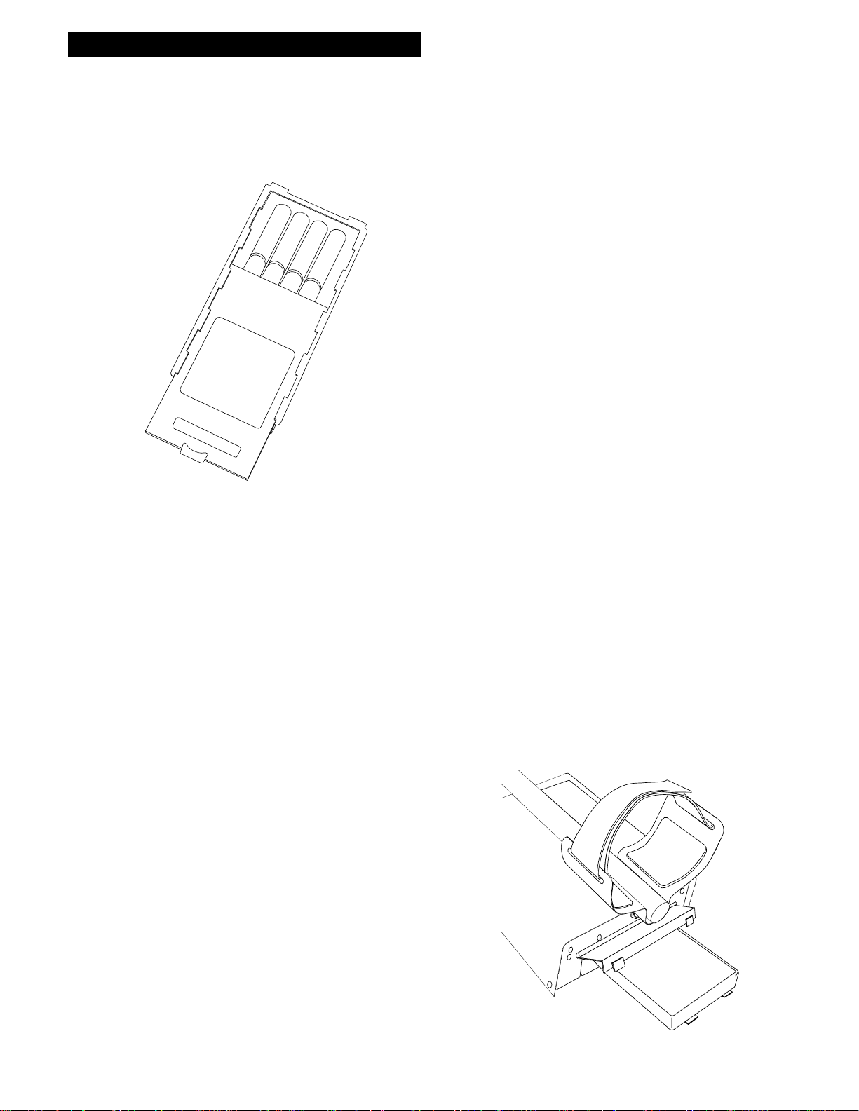
4. Insert the battery holder into the detector so that
the decal is facing down, with the battery
holder door tab and metal contact points facing
toward the inside of the battery compartment.
Close the battery compartment door and secure the
two latches on the bottom of the case. Hook the
front of each latch first, then press down on the
rear.
CAUTION
Battery Holder #802-7150
LIFT TAB AND PULL
Standard Battery Holder
1. The standard battery holder holds eight “AA”
cell batteries. Alkalines are recommended for use
with this model. During normal searching condi-
tions you can expect about 40 or more hours of
hunting time from one set of eight alkaline
batteries.
2. Non-alkaline batteries can be used in this holder.
When non-alkalines or rechargeable “AA”
cells are used, detecting time (before replacement/
recharge) may be reduced to about 30-35
hours.
3. Once the batteries become weak, the beep over
metal targets will be reduced in volume.
Shortly thereafter, the instrument will no longer
respond to metals. The Audio-Boost toggle
has a battery test position in the spring-loaded
down position. Battery level is noted on meter.
4. The battery compartment opens by gently
pulling down on the front of each of the two
latches (on the bottom of the control box) releasing
the catch and hinging open the door.
5
Chapter 2 GMT Batteries
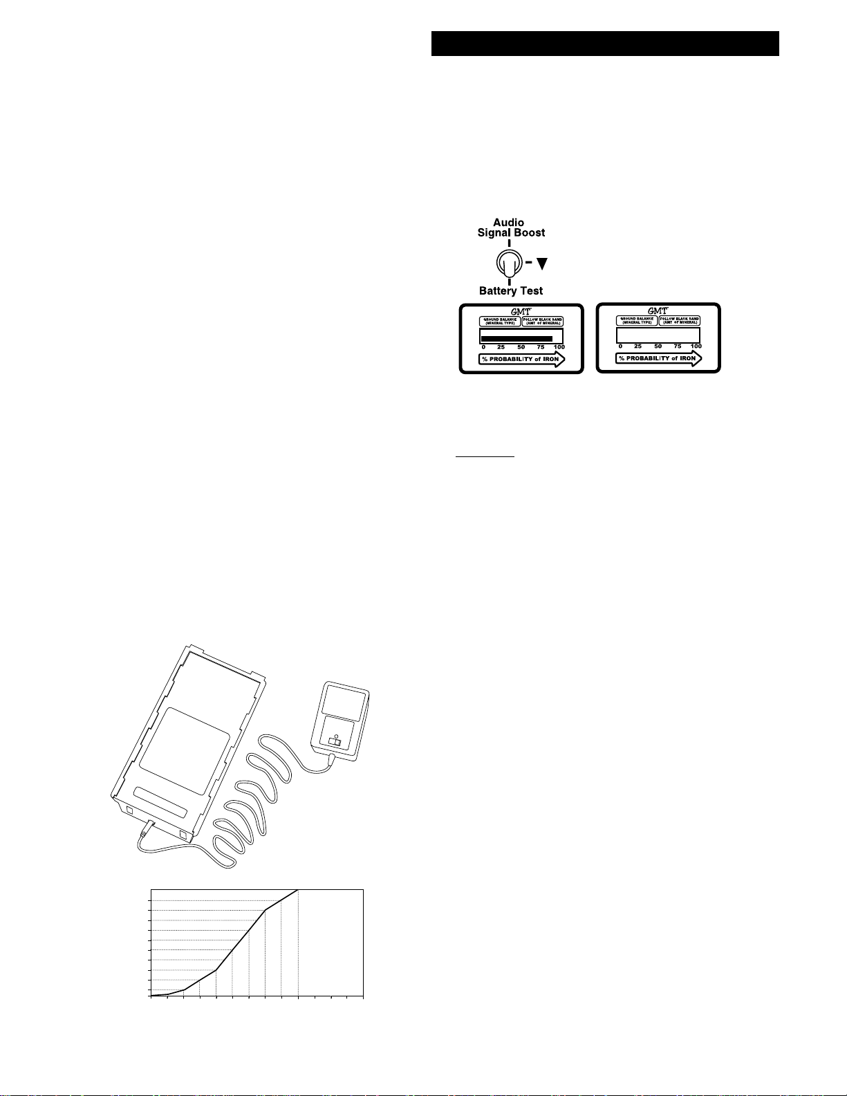
Battery Check
When the Battery Test toggle is pressed downward,
battery condition is indicated on a bargraph on the
LCD display, and by audio pitch. If the batteries
are not fresh, audio loudness on big targets will not
be as great, but there will be no loss of sensitivity or
performance. Since Nicads and Alkalines die at
different voltages, it is not possible to have a Low
Bat & Bat OK indication, however the bargraph
fills to the right on a fully charged battery pack. As
the battery life drops you will note the bargraph
diminish. When the bargraph gets close to the left it
is time to replace or recharge. At this point the
bargraph changes to a message, "SORRY! LOW
BATT". Typical battery life will be in the neighbor-
hood of 40 hours or more.
Non-rechargeable batteries will start to drop in
voltage as soon as they are put into use and then
slowly diminish in voltage till they die. The Nicad
rechargeable battery pack, however, will diminish
voltage very slowly, in somewhat of a flat line and
then when they begin to lose their charge, the
voltage will drop like a rock. Headphone use pro-
longs all battery life. Battery life will vary a great
deal with temperature, number of target signals,
battery type, brand, and shelf life. Non-rechargeable
batteries may be used until the display indicates
"dead battery", or the audio loudness on large
targets is diminished more than you like. When
traveling far from home it is always a good idea to
carry 8 extra penlight alkaline batteries with you as
well as an extra empty battery holder.
Rechargeable Battery(Opt.)
A rechargeable battery system is not standard
equipment with your GMT, however, high quality
systems are available.
White's rechargeable battery #802-5211, and
charger #509-0022 are recommended and offer
quick charge and overnight charge options.
Rechargeable batteries deliver fairly constant
voltage until they're nearly dead. If you use them
until they are dead, they will deteriorate more
quickly than if you only use them till their voltage
starts to drop significantly. Therefore, recharge-
ables should be taken out of service and recharged
as soon as you notice the battery life starting to fall
substantially below the bargraph position that
corresponds to fully charged batteries.
The White's Rechargeable Nicad battery will not
provide the same amount of continuous use
as a full set of Alkaline batteries.
CAUTION
Battery #802-5211
SORRY!
LOW BATT
13 12 11.5 11 10.5 10 9.5 9 8.5 8 7.5 7 6.5 6
5
4.5
4
3
2.5
2
1.5
1
0.5
0
3.5
Any voltage reading
less than 8 volts-
charge for 5 hours
maximum on
Quick Charge
setting. Further
charging can
damage the
system.
Charging
Hours
Using the Battery Charger on Quick Charge Setting
Battery Voltage Reading
6
GMT Quick Start
Chapter 3 GMT Quick Start
GROUND BALACE Toggle
Two position switch for setting
either Fast AutoTrack or
Manual GROUND BALANCE
GAIN Control
For adjusting signal
strength coming from ground,
targets, and electrical interference
Audio THRESHOLD
Control that establishes
the sound level of the
background "hum"
Variable Self Adjusting Threshold
Speed Control (VSAT) for adjusting
the speed at which the THRESHOLD "hum" recovers
from the affects of changes in ground mineralization.
Audio Signal Boost Toggle
Switch-three position-On,
Off, and Battery Test
Iron I.D. Trigger Switch
three position-Forward,
Center, and Squeeze
1
2
3
4
5
6
7
7
Chapter 3 GMT Quick Start
Quick Start
Instructions
With the GMT properly assembled and the batter-
ies installed, follow the instructions below to start
finding those nuggets!
Set the Ground Balance Toggle to the
Fast Autotrac position. "▼"
Set the Audio Signal Boost to the center
(OFF) position. "▼"
Set the IRON I.D. toggle (under the hand
grip) to the center (Audio Iron I.D. OFF)
position.
Set the Variable SAT Speed between the
3x and 4x position. "▼"
Turn the GAIN control clockwise until the
power clicks "ON".
While holding the detector with the
search coil in the air, rotate the GAIN
control clockwise to a point between the
7 & 8 position. "▼"
Turn the THRESHOLD control fully
counterclockwise, then turn it clockwise
until you hear a soft threshold "hum".
Lower the search coil to the ground, then
“pump” the coil up and down 2"-4" a
couple of times and Fast AutoTrac will
automatically balance or track out the
ground mineralization.
Start swinging the search coil in wide
sweeps that overlap each other.
If you experience false signals or constant
beeping or popping, turn the GAIN down
a bit. You may notice a slight fluctuation in
the THRESHOLD “hum” as the GMT
tracks out the ground mineralization. Also,
1
2
3
4
5
6
7
8
9
10
if the meter and audio indicate "Bad Ground"
turn the GAIN down till overload goes away.
* SPECIAL NOTICE* SPECIAL NOTICE
* SPECIAL NOTICE* SPECIAL NOTICE
* SPECIAL NOTICE
If you attempt to demonstrate or test the
GMT by waving targets in the air in front
of the search coil, it is ESSENTIAL to
have the GROUND BALANCE toggle in
the MANUAL position, NOT FAST
AUTO TRAC
This is necessary, for when the GMT is in
the FAST AUTOTRAC position, the
search coil must SEE ground while it is
passing over the target or it will think
that the target IS ground and will attempt
to track it out. This is the case whether
you are demonstrating with or without
Iron ID.
You may, however, demonstrate the fast
ground balancing feature of FAST
AUTOTRAC or GRAB by waving or
pumping a mineralized rock in the air in
front of the search coil.
Thus, testing the GMT with targets while
in FAST AUTOTRAC must be done in or
on the ground.
8
Chapter 4 GMT Controls
Gain Control/Power Off
With the GAIN control, you increase the signal
strength coming from the ground. You might expect
increased signal strength to always find more
nuggets at greater depths. However, high ground
mineralization will "bounce" the signal back and
mask good targets. It is therefore necessary to
ADJUST the GAIN to give you the maximum
allowable GAIN without masking targets or over-
loading the circuit and at the same time allowing
you to operate the detector with a constant threshold
hum so that faint signals can be detected.
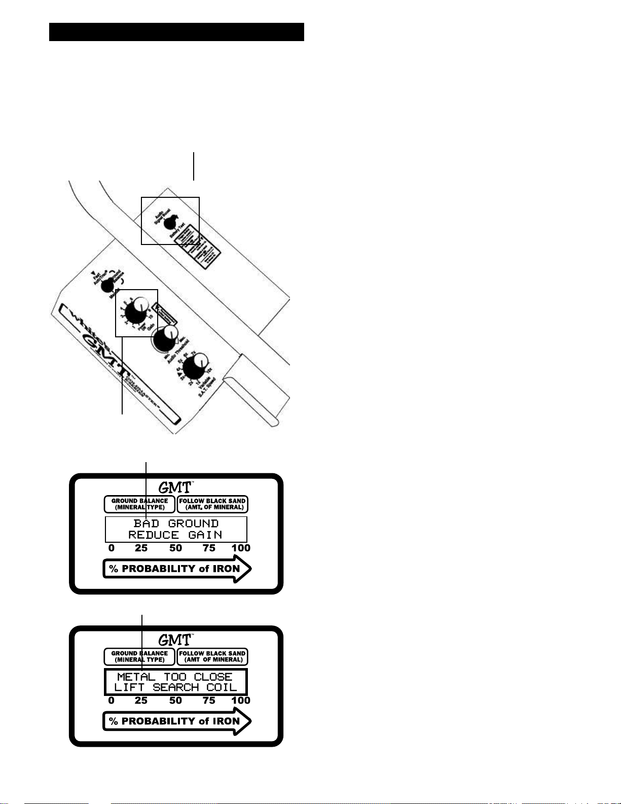
This is where the new GMT can help you out.
When ground mineralization is too high for the
current GAIN control setting, the display flashes
"BAD GROUND-REDUCE GAIN" along with
an audible "squawk". Reduce the GAIN till the
overload warning ceases. On occasion, while
searching, you might go over a very large or very
shallow target. The message on the LCD display
will read "METAL TOO CLOSE LIFT
SEARCHCOIL". All such targets should be
checked but the GMT will self correct after the
message and you can continue to search as normal.
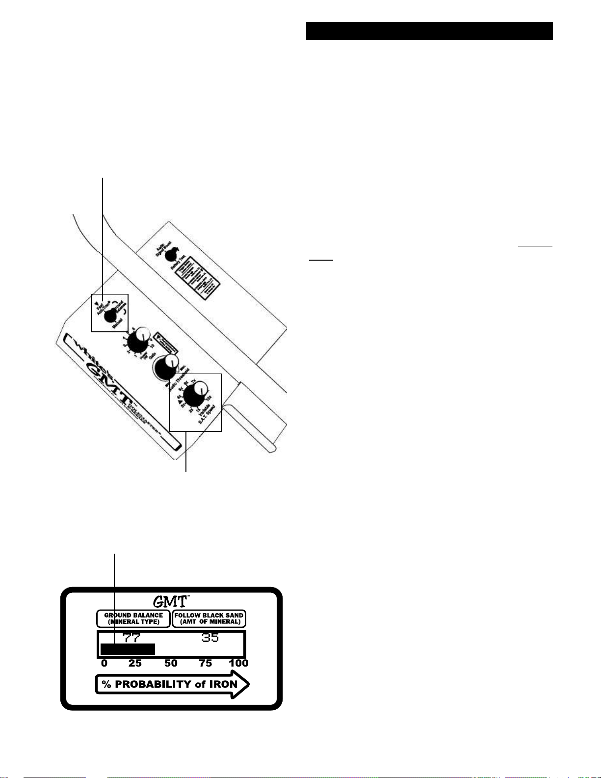
Gain Adjustment
1. The GAIN control knob turns the GMT ON and
OFF and controls the GAIN. Starting from the
POWER OFF position and going clockwise, the
power is turned ON and the dial increases the
GAIN from a minimum level of "1" to a maximum
level of "10". Set the control to the "Initial Setting
Triangle" ( between level 7& 8 ). While performing
this adjustment, make sure that the AUDIO SIG-
NAL BOOST toggle is in the OFF position.
2. Although the setting of (7-8) gives more than
ample GAIN, if the ground mineralization is low
enough, you might attempt to raise the GAIN above
this level toward 10. If, of course, "BAD GROUND
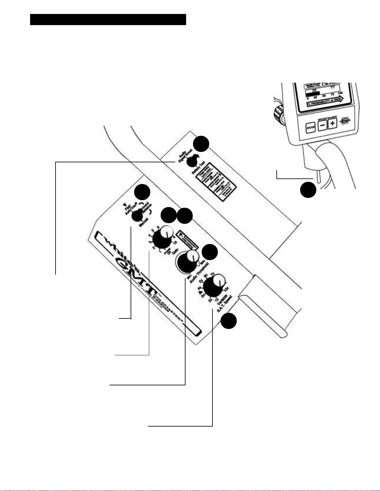
GAIN CONTROL
BAD GROUND ALERT MESSAGE
AUDIO SIGNAL BOOST
Controls
GROUND MINERALIZATION TOO IGH MESSAGE
LARGE OR SHALLOW TARGET MESSAGE
9
Gain Adjustment
(cont'd)
REDUCE GAIN" message is flashed, you must
heed it and reduce the GAIN rather than raise it.
3. The object of increasing the GAIN is to get the
maximum available depth from the detector WITH-
OUT causing the "BAD GROUND" message to
appear, which indicates an overload of the circuit.
4. In addition, any increase in GAIN adjustment
should NOT BE at the expense of maintaining a
smooth and constant THRESHOLD "hum". False
signals, beeps and bops from bits of mineralization,
erratic behavior, and lapses in THRESHOLD all
can be the result of running with too much GAIN.
5. The use of the VSAT (variable self-adjusting
threshold) control will also help to maintain a
smooth THRESHOLD "hum" and will be covered
in a later section.
6. While using a steady slow search coil sweep
speed, advance the control towards "10" while
maintaining a quiet smooth background THRESH-
OLD "hum". If the "BAD GROUND-REDUCE
GAIN" alert keeps popping up on the display or if
ground noises are still a problem reduce GAIN.
7. The IRON ID capability of the GMT also
functions more accurately when the GAIN is set at
a level which allows for smooth operation. Too
much GAIN can cause bad ground to distort the
proper identification of iron and non-iron targets.
In addition, just as a slow, broad search-coil speed
will maintain smooth threshold, it will also allow
the search-coil to get clear off of the target with
each pass, thus insuring that the GMT "sees"
ground as well as target. This is essential for the
accurate operation of % of Iron Probability ID.
FAST AUT OTRAC
POSITION
ON GROUND BALANCE
TOGGLE SWITCH
VSAT SPEED CONTROL
IRON I.D. BARGRAPH
Chapter 4 GMT Controls
 Loading...