

Page 1
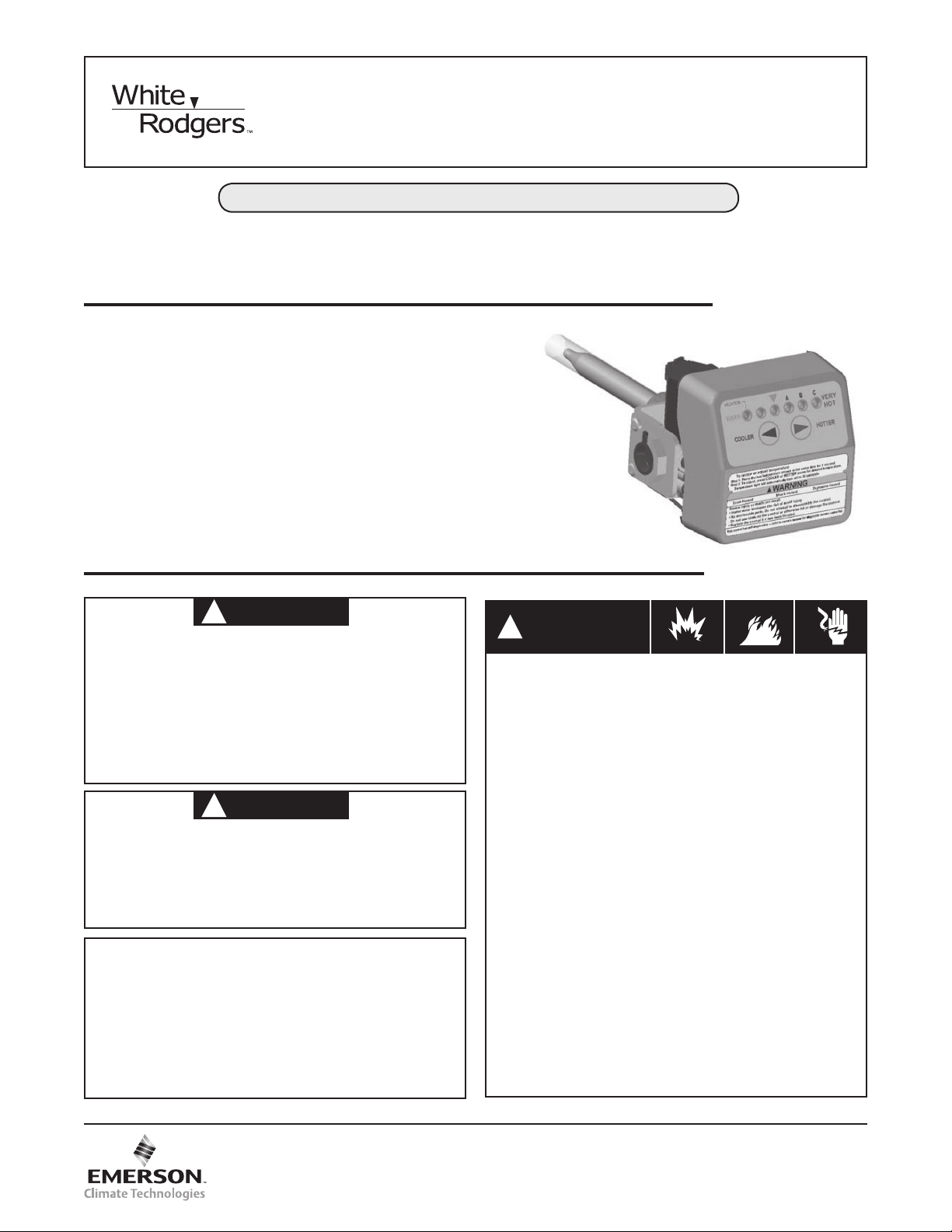
37E73A-918, 921, 922 or 927 INTELLI-VENT™
WARNING
!
WARNING
!
WARNING
!
Water Heater Thermostat Control Installation Instructions
Operator: Save these instructions for future use!
FAILURE TO READ AND FOLLOW ALL INSTRUCTIONS CAREFULLY BEFORE
INSTALLING OR OPERATING THIS CONTROL COULD CAUSE PERSONAL
INJURY AND/OR PROPERTY DAMAGE.
The 37E73A-9XX INTELLI-IGNITION™ control is a
combination gas valve, ignition control, and thermostat for
use on Power Vented water heaters. The microcomputer in
the control supervises the ignition sequence and timings
for the water heater, and provides diagnostic codes in case
of system malfunction. The control provides direct burner
ignition using the White-Rodgers’ Silicon Nitride ignitor. The
control uses the INTELLI-IGNITION™ technology to greatly
extend the ignitor’s life.
Adjustable Regulator Controls: The gas regulator on this
control requires no field service. The regulator is factory
adjustable for the proper burner gas pressure.
For Natural Gas Only
DESCRIPTION
“WHAT TO DO IF YOU SMELL GAS”
•Do not try to light any appliance.
•Do not touch any electrical switch; do not use any
phone in your building.
•Immediately call your gas supplier from a neighbor’s
phone. Follow the gas supplier’s Instructions
•
If you cannot reach your gas supplier, call the fire
department.
Do not use this Natural Gas control on LP Gas water
heater. Improper operation could occur, resulting in
personal injury and/or death due to Carbon Monoxide
(CO) poisoning, fire, or explosion. Check for proper
gas type as listed on the rating plate affixed to the
water heater.
.
CONTENTS
Description ............................................................. 1
Precautions ............................................................ 1
Specifications ......................................................... 2
Installation .............................................................. 2
Operation ................................................................ 7
Wiring ..................................................................... 6
Troubleshooting ...................................................... 8
PRECAUTIONS
FIRE, SHOCK AND EXPLOSION HAZARDS
• Shutoffmaingastoapplianceforserviceoruntil
installation is complete.
• Disconnectelectricpowerbeforeservicing.
• Donotexceedthespeciedvoltage.
• Replace existing control with recommended
model.
• Protectthecontrolfromdirectcontactwithwater
(dripping, spraying, rain, etc.)
• Ifthecontrolhasbeenindirectcontactwithwater,
replace the control.
• Labelallwiresbeforedisconnectionwhenservicing controls. Wiring errors can cause improper and
dangerous operation.
• Routeandsecurewiringawayfromame.
• Ensureproperearthgroundingofappliance.
• Ensureproperconnectionoflineneutralandline
hot wires.
• Donotusetoolstooperatethiscontrol.
• Donottakecontrolapart,therearenoserviceable
parts inside.
• Donotusecontrolifithasbeenooded.
• Neverstandonthecontroloruseasastep.
www.white-rodgers.com
www.emersonclimate.com
PART NO. 37-7110A
0950
Page 2

SPECIFICATION
NOTE
NOTE
ELECTRICAL RATINGS:
Input and Frequency: 120 VAC, 60 Hz
Output Ratings:
Ignitor Load: 2 Amps maximum
Inducer Draft Motor: 3 Amps Full Load, 4 Amps Locked
Rotor
Current: 0.2 Amps @ 120 VAC
Range of Regulation (Btu/Hr)
Minimum: 30,000 Maximum: 150,000
Pressure Regulator Setting: Factory set to 3.5” or 4.0” W.C.
Adjustable 2.5” to 5.0” W.C.
1.0” Pressure Drop Capacity
100,000 Btu/Hr
a
Based on 1000 Btu/ft3, 0.64 specify gravity natural gas
Maximum Inlet Pressure: 1/2 PSI maximum
Ambient Temperature Rating:
32oF to 160oF (0oC to 70oC )
a
Automatic High Temperature Cutoff:
Single-Use Type, 185oF(82oC)
Prepurge Time: 5 Seconds
Ignitor Warm-up Time: 20 Seconds
Trial for Ignition Period: 4 Seconds
Inter-purge Time: 5 Seconds
Post-purge Time: 5 Seconds
Ignition Retries: 2 Retries; 3 Trials before lockout
Ignition Recycles: 2 Recycles, 3 Losses of flame before
lockout
BODY CONFIGURATION:
Right angle with a 1/2” NPT inlet and a 1/2” inverted flare
outlet
MOUNTING:
Limited Horizontal/Vertical
INSTALLATION
Dirt or contamination in the gas line can block the control
from operating creating a risk of explosion, injury, or death.
1. This control must be installed or serviced only by a
professional.
2. For your safety, this control is supplied with tamper
resistant screws. Do not attempt to repair or adjust
the control. If you experience problems, replace the
control immediately. Continuing to use a damaged
control could result in fire and/or explosion.
3. An odorant has been added to the gas to help you
detect it. Before lighting, search for the odor of gas by
snifngatoorlevelaroundthewaterheater.
4. In some situations, the gas may lose its odor. To
detect unodorized gas, you must have a gas detector,
which can be purchased from your gas company. If
you do not have a detector and have the slightest
suspicion that gas may be present, get out of the
house and call the gas company. DO NOT RELY
TOTALLY ON YOUR NOSE.
REMOVING THE OLD CONTROL
1. Shut off the gas to the water heater
2. Turn off electrical power to the water heater.
3. Remove the two plastic wire connectors that plug
into the bottom of the control. The connectors have
latches which must be depressed. DO NOT FORCE
THE CONNECTORS, DAMAGE TO THE WIRING MAY
RESULT.
4. Shut off the water at the cold water inlet.
5. Connect a hose to the water heater drain cock. Drain the
water to a nearby drain. Open a hot water faucet for faster
draining.
6. Disconnect the gas line at the union (Figure 1). Remove
the piping from the old control.
7. Remove the control by turning it counterclockwise ( ).
INSTALLING THE NEW CONTROL
All piping must comply with local and state ordinances or
with the National Fuel Gas Code (ANSI Z223.1-NFPA 54),
whichever applies.
2
To protect the control from dirt and contamination, a drip leg
or sediment trap (see Figure 1) must be installed in the piping
leading to the control.
1. Apply pipe compound to the male threads of the pipe that
goes into the control, leaving the first two or three threads
clean.
2. Install control in the tank. Turn clockwise (
short piece of pipe to help in turning. Align the control so
that the burner tube may be connected.
3. Make the main burner connection. Do not use pipe joint
compound or Teflon tape.
4. Connect the gas line. Use new black iron pipe that has
been properly reamed. If old pipe is used, be sure it
is clean and free from rust and scale. Use pipe joint
compound on male threads only. (Use pipe joint compound
approved for natural and LP gas service.) Do not use
TEFLON tape. Do not apply compound to the first two
threads.
5. DO NOT use joint compound or tape on the union
connection.
6. Make the electrical connections to the control. There are
two plastic connectors that plug into the bottom of the
control. The connectors are “keyed” so that they can only
be inserted one way. Make sure that the connectors
are properly aligned before attempting to insert. DO
NOT FORCE THE CONNECTORS; DAMAGE TO THE
CONTROL WILL RESULT.
7. To fill the water heater with water:
a. Close the water heater drain valve by turning the
handle to the right (clockwise). The drain valve is on
the lower front of the water heater.
The cold water supply valve must be left open when the
water heater is in use.
b. Open the cold water supply valve to the water heater.
c. To ensure complete filling of the tank, let air exit by
opening the nearest hot water faucet. Allow water to
run until a constant flow is obtained. This will let air out
of the water heater and the piping.
). Use a
Page 3
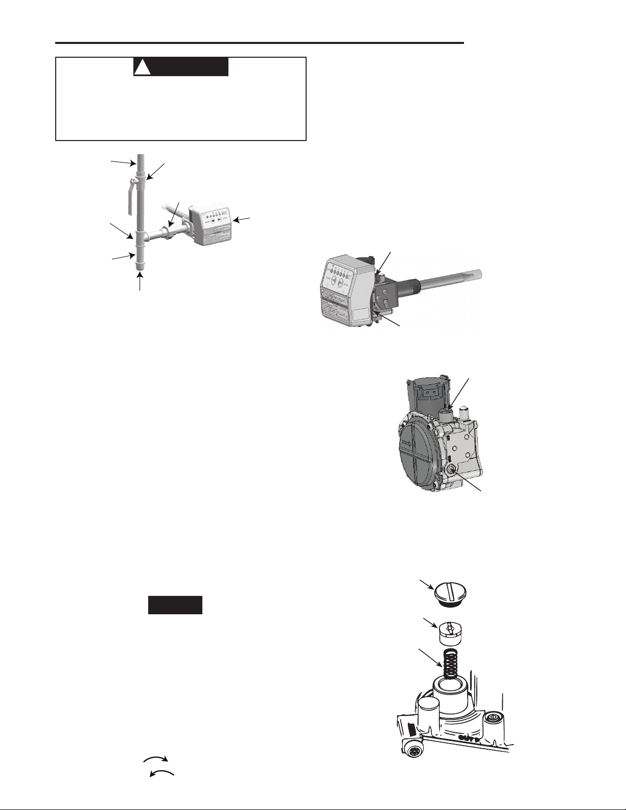
GROUND JOINT UNION
INTELLI-VENT™
CONTROL
GAS SUPPLY
PIPE
TEE
DRIP LEG
(SEDIMET TRAP)
3" MINIMUM
(MANDATORY)
PIPE CAP
SHUT-OFF VALVE
CAUTION
!
Never use this water heater unless it is completely
NOTE
filled with water. To prevent damage to the tank, the
tankmustbelledwithwater.Watermustowfrom
the hot water faucet before turning ON gas to the
water heater.
Figure 1. Typical gas connection
d. Check all new water piping for leaks. Repair as needed.
8. Open the gas shutoff valve.
9. BEFORE TURNING ON THE APPLIANCE, CHECK THE
GAS LINES FOR LEAKS.
a. Use a soapy water solution. DO NOT test for gas leaks
using a match or open flame.
b. Brush the soapy water solution on all gas pipes, joints,
and fittings. Use care that excess solution does not
enter the control’s plastic housing.
c. Check for bubbling soap. This means you have a leak.
Turn OFF the gas and make the necessary repairs.
d. Turn on the gas and recheck for leaks. Repeat this
process until you are sure the system is gas-tight. If
repeated work on a part does not stop the leak, the
part must be replaced.
e. Rinse off the soapy solution and wipe all the plumbing
parts dry.
PRESSURE REGULATOR ADJUSTMENT
These controls are shipped from the factory with the regulator
set as specified on the control label. Consult the appliance
rating plate to ensure burner manifold pressure is as specified.
If another outlet pressure is required, follow these steps.
INSTALLATION
fig. 3). Always adjust regulator to provide the correct
pressure according to the original equipment manufacturer’s
specifications listed on the appliance rating plate. Replace
regulator cover screw.
6. Turn off all electrical power system to the system.
7. Remove manometer hose from outlet pressure tap.
8. Remove hose fitting and re-install the 1/8 NPT pressure
tap plug. Tighten to 60 in-lb max.
9. Turn on electrical power to the system.
10. Turn on system power and energize valve.
11. Using a leak detection solution or soap suds, check
for leaks at pressure boss screw or pressure tap plug.
Bubbles forming indicate a leak. SHUT OFF GAS AND FIX
ALL LEAKS IMMEDIATELY.
Outlet Pressure
Regulator Adjust
Tower
1/8 Threaded Outlet
Pressure Tap
37E Intelli-Vent™ Control
Outlet Pressure
Regulator Adjust
Tower
1/8 Threaded Outlet
Pressure Tap
36G Valve
Figure 2. Pressure port and regulator adjust locations
Regulator
Cover Screw
If a valve has been factory-adjusted for the 2.5 to 5 inches
W.C. range, it cannot be field-adjusted outside that range.
1. Turn off all electrical power to the system
2. These models have 1/8 NPT threaded taps. The outlet
pressure tap plug will need to be removed and a separate
hose fitting installed.
3. Attached a hose and manometer to the separate hose
fitting which has been installed in place of the 1/8 NPT
threaded tap.
4. Turn on system power and energize valve.
5. Remove regulator cover screw and turn regulator adjust
screw clockwise (
) to increase pressure, or
counterclockwise ( ) to decrease pressure (see
Plastic
Adjust Screw
Regulator
Spring
Figure 3
3
Page 4
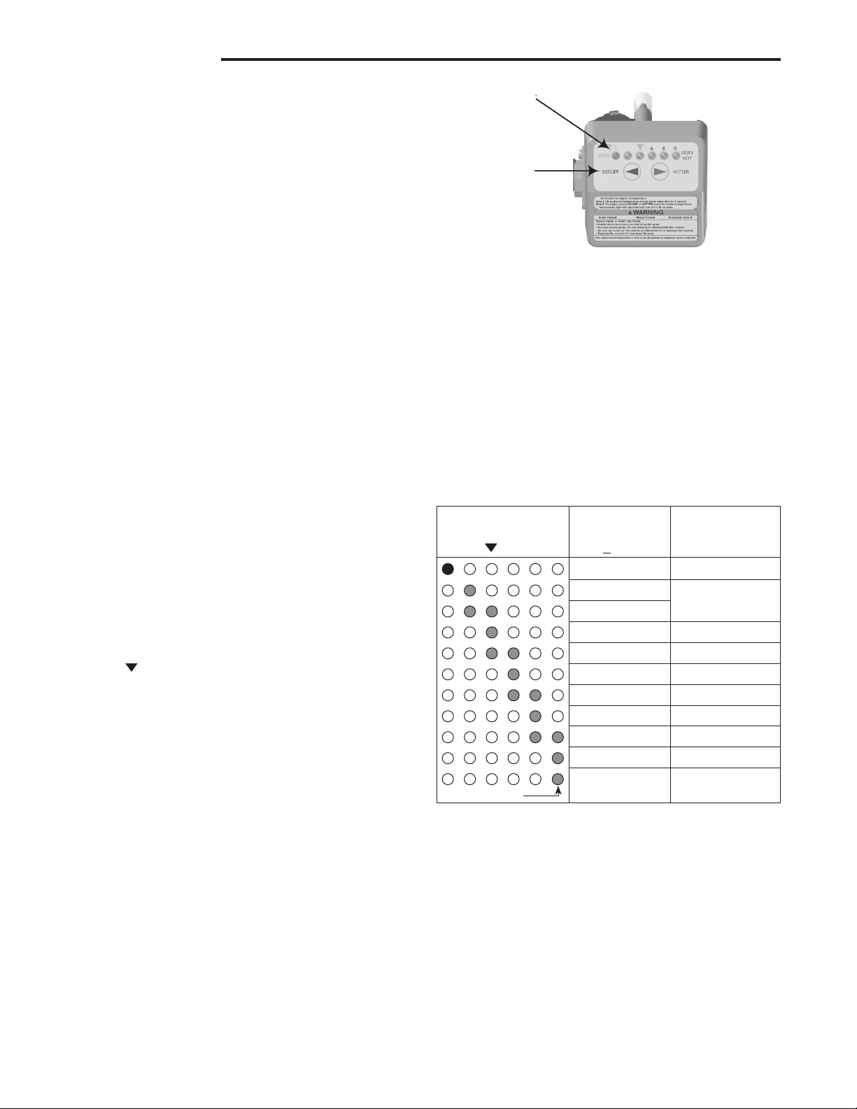
TEMPERATURE
INDICATORS
TEMPERATURE
ADJUSTMENT
BUTTONS
70 (Vacation)
N/A
INSTALLATION
OPERATING INSTRUCTIONS
1. The control uses an automatic ignition system to light
the burner. DO NOT TRY TO MANUALLY LIGHT THE
BURNER.
2. Wait at least five (5) minutes to clear out any gas, and
then smell around the appliance area near the floor. If you
smell gas, STOP! Follow the instructions “What to do if
you smell gas” on the first page of this instruction sheet.
If you do not detect gas, continue with the next step.
3. Make sure that both the inner and outer doors are in place.
These doors are located where the burner tube enters the
water heater at the bottom. Both doors must be in place
for safe operation.
4. Turn on power to the water heater. This can be done either
by turning on the disconnect switch to the water heater,
or plugging in the water heater to a nearby outlet. The installer should have made this provision for you, and it must
meet local and state ordinances or the National Electric
Code, whichever applies.
5. For a brief time (one to five seconds) all of the indicators
on the front of the control should come on, and then turn
off. This indicates that the control has completed the selfdiagnostic test, and is ready for operation. If any combination of indicators remain illuminated, either refer to the
troubleshooting section of this manual, or contact a qualified service person.
6. The water heater is now ready for operation, and will
begin to heat the water to the factory default setting of
approximately 70°F. If an alternate temperature setting is
required, please refer to the following section “Temperature
Regulation”.
Figure 4. Temperature Indicators and Adjustment
b. To increase the temperature press and release the
HOTTER button once. The temperature indicators will
now display the new temperature setting.
Press and release the HOTTER button until you have
reached the desired setting. HOLDING DOWN THE BUTTON
WILL NOT CONTINUE TO RAISE THE SETTING. The Button
must be pressed and released for each temperature change
desired.
To avoid scald injury, set the control to the lowest setting
which will deliver your needed hot water. Refer to Table 1 to
determine the approximate temperature setting, and the approximate time for scald injury at that temperature.
Table 1. Temperature Settings
Display
A B C
Approximate
Temperature
(+10
o
F)
Approximate
Time to Cause
Injury
TEMPERATURE REGULATION
After the gas and electrical connections are made and the
water heater tank is full of water, the control will now start to
heat the water to the factory default setting of approximately
70°F. If a higher setting is desired, start with the setting at the
triangle ( ). This is approximately the 120°F setting, and the
safest and most economical setting for the water heater.
To change the temperature setting for either cooler or warmer
water, the following steps are necessary:
1. “Wake up” the temperature indicators by pressing the
COOLER and HOTTER temperature adjustment buttons at
the same time and releasing after one second (see Figure
4). One or two of the temperature indicators will light up.
These indicators will only remain on for 30 seconds if no
further buttons are pressed. After 30 seconds the control
will go back to “Sleep” mode, and both buttons will again
have to be pressed to see the water temperature setting.
2. If this is the first time that the control has been used, the
leftmost green indicator will be illuminated indicating the
water temperature setting of approximately 70°F. See Table
1 for an explanation of what each of the temperature indicators mean.
a. To decrease the temperature press and release the
COOLER button once. The temperature indicators will
now display the new temperature setting. Press and
release the COOLER button until you have reached the
desired setting. HOLDING DOWN THE BUTTON WILL
NOT CONTINUE TO LOWER THE SETTING. The
Button must be pressed and released for each temperature change desired.
110
115
120
5 minutes
125
130
30 seconds
135
140
5 seconds
145
Flashing
150
160 Under 1 second
1.5 seconds
3. When you have completed setting the control wait 30
seconds to see that the temperature indicators go off and
the control enters “Sleep” mode. ALL OF THE TEMPERA-
TURE INDICATORS WILL BE OFF DURING NORMAL
OPERATION. If any time you see the indicators on, there
may be a system error and you should consult the “Troubleshooting” section of this document, or contact a trained
service professional.
If you use hot water frequently and in short spurts, water temperature can occasionally exceed the temperature setting by
up to 30°F because of the dynamics of the appliance. Keep
this in mind when you are selecting a temperature higher than
the factory default setting.
Be sure to protect babies and the infirm or others with impaired mobility who cannot get out of the hot water quickly.
4
Page 5

WARNING
!
WARNING
!
Scald burns occur in under one second with 160°F
water, which this thermostat will deliver if the
temperature is set at “VERY HOT”. Lower settings of
the temperature will reduce the risk of scald and will
reduce your fuel bill.
They are the people most commonly hurt in scald injuries
and in need of lower temperature and other protection like
supervision, point-of-use temperature control equipment or a
system mixing valve. A point-of-use valve or system mixing
valve can be obtained from your local plumber.
Checking the temperature setpoint may be performed at any
time by the procedure described on step 1 of “Temperature
Regulation” on page 4. No other action is needed for checking temperature setpoint.
SHUTTING OFF THE APPLIANCE
Vacation Shutdown
INSTALLATION
2. Press and release the COOLER button as many times as
needed until the green leftmost indicator is only lit. This
temperature setting is approximately 70°F. Leave the gas
turned on.
3. When returning from vacation reset the temperature to
that you noted in step 1.
Complete Shutdown
1. Turn off the electrical disconnect on the appliance, or
remove the plug from the receptacle, whichever applies.
(Don’t worry; the Intelli-Vent™ control will remember your
correct temperature setting.)
2. Turn off the gas supply to the water heater. The water
heater is now completely shut down.
3. To restart the water heater, follow the instructions in the
section “Operating Instructions”.
There are no user serviceable parts in this control. The
control is supplied with tamper resistant screws. DO NOT
attempt to repair or adjust the control. If you experience problems, discontinue use and replace the control immediately.
Continuing to use a damaged control could result in fire
and/or explosion.
Never allow small children to use a hot water tap, or
to draw their own bath water. Never leave a child or
impaired person unattended in a bathtub or shower.
Scald burns can result
1. “Wake up” the temperature indicators by holding down both
the COOLER and HOTTER temperature adjustment buttons at the same time for one second (see Figure 2). One
or two of the temperature indicators will light up. Make a
note as to which indicators are illuminated so that you can
reset the control to the same setting when you return from
vacation.
Service
If you wish to verify that the water heater is operating properly:
1. Make sure there is power to the water heater.
2. Make sure that the gas is turned on to the water heater.
3. Initiate a call for heat by either drawing hot water from a
nearby faucet or raising the temperature setting (see section “Temperature Regulation”).
4. Watch the ignition sequence and compare it to the “Sequence of Operation” chart on page 7.
5. Note any error codes that appear and proceed to the next
section “Troubleshooting”.
5
Page 6

HIGH
LIMIT
SWITCH
AIR
PRESSURE
SWITCH
COMBUSTION
BLOWER
BLACK
WHITE
GREEN
TO POWER SUPPLY
DISCONNECT
AND OVERLOAD
PROTECTION
IGNITOR AND
FLAME PROBE
ASSEMBLY
INSET
Intelli-Vent™ Wiring Diagram
Typical Installation
(Consult Appliance Manufacturer's Instructions For Details)
BOTTOM VIEW
INTELLI-VENT CONTROL
TM
FLAMMABLE
VAPOR
SENSOR
(IF EQUIPPED)
WIRING DIAGRAM
A typical system wiring diagram is shown below. Use the
water heater manufacturer’s wiring diagram for details of the
installation. Always follow the instructions supplied with the
water heater, and those of the water heater manufacturer.
6
Page 7

SEQUENCE OF OPERATIONS
APPLY POWER TO
APPLIANCE
IS FIELD WIRING
CORRECT?
DISPLAY ERROR CODE
1
OR
2
NO
YES
REQUEST
FOR HEAT
PRESENT?
NO
IS
PRESSURE SWITCH
PROVEN OPEN WITHIN
5
SECONDS?
YES
NO
COMBUSTION
BLOWER ON
YES
IS
PRESSURE SWITCH
PROVEN CLOSED
WITHIN
5
SECONDS?
NO
WAIT FOR PRESSURE
SWITCH TO OPEN
DISPLAY ERROR
NUMBER
3
WAIT FOR PRESSURE
SWITCH TO CLOSE
DISPLAY ERROR
NUMBER
4
PREPURGE
IS
IGNITOR
OKAY?
TURN OFF INDUCER
DISPLAY ERROR CODE
NUMBER
5
NO
IGNITOR ON FOR
WARM-UP TIME
YES
YES
MAIN VALVE OPENS
MAIN
BURNER LIGHTS
AND IS SENSED
DURING TRIAL
FOR
IGNITION
IGNITOR TURNS OFF
YES
NO
IS
FLAME SENSE
LOST?
IS
REQUEST FOR HEAT
SATISFIED?
MAIN VALVE OFF
COMBUSTION
BLOWER OFF AFTER
POST-PURGE DELAY
MAIN VALVE CLOSES
LESS
THAN
3
TRIES
FOR IGNITION?
MAIN VALVE CLOSES
LOST
LESS THAN
3
TIMES?
YES
YES
TURN OFF INDUCER
AFTER POST-PURGE
DISPLAY ERROR
6
ONE HOUR AUTO
LOCKOUT RESET
DELAY
NO
NO
NO
YES
YES
NO
Intelli-Vent™
Sequence of Operation
Please Note:
The control continually monitors
internal circuits and external sensors.
Error codes noted above, and those for
self-diagnostic faults can be found on
pages 8 and 9.
IS
PRESSURE SWITCH
PROVEN OPEN WITHIN
5
SECONDS?
WAIT FOR PRESSURE
SWITCH TO OPEN
DISPLAY ERROR
NUMBER
3
COMBUSTION
BLOWER ON
IS
PRESSURE SWITCH
PROVEN CLOSED
WITHIN
5
SECONDS?
WAIT FOR PRESSURE
SWITCH TO CLOSE
DISPLAY ERROR
NUMBER
4
INTERPURGE
COMBUSTION
BLOWER OFF
YES
NO
NO
YES
YES
7
Page 8

1
An open earth ground circuit to the ignition system
1. Check that the earth ground conductor is properly
connected at the fuse box or breaker panel and the
water heater.
2. Check that the grounding conductors on the water
heater are properly connected and secure.
2
The self diagnostic test
detected a wiring error or
a high resistance to earth
ground
1. Check for proper connection of the line neutral and
line hot wires.
2. Check that the appliance is securely connected to
earth ground.
3
The pressure switch remained closed longer that
5 seconds after the call for
heat began.
1. The pressure switch wiring is incorrect.
2. The pressure switch is defective and must be
replaced.
ABC
4
The pressure switch remained open longer than 5
seconds after the combustion blower was energized
1. The pressure switch wiring is incorrect.
2. The pressure switch tubing is not connected correctly.
3. Obstructions or restrictions in the water heater air
intake or exhaust flue.
ABC
5
The self diagnostic test has
detected an error in the Hot
Surface Ignitor circuit.
1. Check that all wiring is correct and secure.
2. Disconnect the ignitor and measure the ignitor resistance with an accurate ohmmeter between pins
1 and 2. Resistance should be between 11.5 and
18.8 ohms. If the reading is incorrect, replace the
Hot Surface Ignitor.
3. If the above checks are good, replace the INTELLIVENT™ control.
ABC
6
The maximum number of
ignition retries or recycle
has been reached and the
system is in lockout
1. Check if the gas supply is off or too low to operate.
2. Check that the flame sense rod to see that it is
located properly and free from contamination.
Reposition the flame sense rod or lightly clean with
an abrasive cloth.
3. The Hot Surface Ignitor may not be positioned correctly. Reposition as necessary.
4. The Hot Surface Ignitor and Flame Sense Rod
wired correctly and in good working condition.
Repair as required.
5. Low voltage to the water heater. Check and repair.
TROUBLESHOOTING
2341
The troubleshooting charts cover the error codes that the
Intelli-Vent™ control can recognize, the potential cause, and
those actions that may help repair the problem. The water
heater manufacturer’s troubleshooting procedure should be
consulted before attempting to repair the appliance. The water heater manufacturer’s instructions take priority over the
instructions here.
If for any reason you question your ability, or feel any doubt
about your ability to perform any of the troubleshooting procedures or repairs recommended. STOP! Contact a trained
and qualified service professional to repair the water
heater.
To troubleshoot the system using the error code indicators:
1. Check that the system is currently active and calling for a
request for heat. You can initiate a call for heat by either
drawing hot water from a nearby faucet or raising the tem-
Error Indication Check, Repair, or Replace
perature setting (see section “Temperature Regulation”).
If you have noted an error code from a previous heating
cycle, this step is not necessary, and you may proceed
with the next step.
2. Refer to the troubleshooting charts on below to find the
error code that is displayed. Check and repair those items
recommended.
3. Once the repair is complete, again initiate a call for heat,
and observe that the ignition sequence complies with that
shown on page 7.
4. After the water heater repair is complete, return the water
heater temperature setting to the original temperature. If
for any reason you cannot remember the original setting,
return the setting to the 120
o
F setpoint. See the section
“Temperature Regulation” for assistance in setting the water temperature setting.
8
Page 9

TROUBLESHOOTING
ABC
7
The self diagnostic test
found a problem with the
gas valve driver circuit
1. Cycle power to the water heater off for 10 seconds
and then back on.
2. If the above step did not cleat the error, the INTELLI-VENT™ control must be replaced
ABC
8
The self diagnostic test has
detected a problem with
the internal microcomputer.
1. Cycle the external power off for 10 seconds and
then back on.
2. If the above step does not clear the error, the
INTELLI-VENT™ control must be replaced.
ABC
9
The self diagnostic test has
detected a problem with
the internal circuit
1. Cycle the external power off for 10 seconds and
then back on.
2. If the above step does not clear the error, the
INTELLI-VENT™ control must be replaced.
ABC
10
Flame signal sensed out of
proper sequence.
1. Replace the INTELLI-VENT™ control.
ABC
11
The high temperature thermal cutoff is open
1. Replace the INTELLI-VENT™ control.
ABC
12
The diagnostic test has detected one of the temperature adjust buttons stuck
closed
1. Make sure that there are no objects leaning against
the front of the control.
2. Lightly press and release each of the buttons once.
3. If the above actions do not clear the error, the
control will continue to regulate water temperature
at the last setting, but you not be able to change
settings unless you replace the INTELLI-VENT™
control.
ABC
13
The self diagnostic test
has detected that the water
temperature sensor is either open or short circuited.
1. Check that all wiring is correct and that there are no
open or shorted circuits.
2. If no wiring problems are found the INTELLIVENT™ control must be replaced by a qualified
service person.
ABC
14
The self diagnostic test
found a problem with the
Flammable Vapor Sensor
1. Check that all wiring is correct and that there are no
open or shorted circuits.
2. If no wiring problems are found the flammable
Vapor Sensor must be replaced.
ABC
15
The control detected the
presence of flammable
vapors near the appliance
and entered lockout.
1. If you smell gas, STOP! Follow the instructions,
“What to do if you smell gas” on page 1 of this
instruction sheet. Otherwise call a qualified service
person for replacement of the control.
Page 10

NOTES
10
Page 11

NOTES
11
Page 12

White-Rodgers is a division
of Emerson Electric Co.
The Emerson logo is a
trademark and service mark
of Emerson Electric Co.
www.white-rodgers.com
www.emersonclimate.com
 Loading...