

Page 1
5D51-35, -78 & -90
WHITE-RODGERS
INSTALLATION INSTRUCTIONS
Operator: Save these instructions for future use!
FAILURE TO READ AND FOLLOW ALL INSTRUCTIONS CAREFULLY
BEFORE INSTALLING OR OPERATING THIS CONTROL COULD CAUSE
PERSONAL INJURY AND/OR PROPERTY DAMAGE.
Fan & Limit Control
DESCRIPTION
This fan and limit control combines, in one enclosure, a
fan switch with an adjustable differential which operates
the blower in a forced warm air furnace and a limit switch
with a fixed differential which automatically shuts off the
burner if the furnace temperature exceeds a predetermined high point.
THIS CONTROL MUST BE INSTALLED BY A QUALIFIED INSTALLER.
All wiring must conform to local and national electrical
codes and ordinances.
This control is a precision instrument, and should be
handled carefully. Rough handling or distorting components could cause the control to malfunction.
This control has been accurately calibrated at the factory.
Any attempt to re-calibrate this control will void the WhiteRodgers warranty.
WARNING
!
Do not use on circuits exceeding specified voltages. Higher voltages will damage control and
could cause shock or fire hazard.
If in doubt about whether your wiring is millivolt,
low or line voltage, have it inspected by a qualified heating and air conditioning contractor or a
licensed electrician.
A summer fan switch is incorporated in this control to
provide a convenient method for manual operation of the
fan for air circulation during the summer.
PRECAUTIONS
CAUTION
!
To prevent electrical shock and/or equipment
damage, disconnect electric power to system at
main fuse or circuit breaker box until installation
is complete.
Label all wires prior to disconnection when servicing controls. Wiring errors can cause improper
and dangerous operation.
Following installation or replacement, follow
appliance manufacturers’ recommended installation/service instructions to insure proper operation.
Removing Cover
To remove cover from control, grasp cover at top and
bottom and pull outward. Grasping the cover by its sides
will make removal more difficult.
Location
1. The bimetal element should not be too close to any
hot surfaces of the heat exchanger. The element
should always be at least 3“ away from any hot
surfaces unless the position has been determined
acceptable by the furnace manufacturer.
WHITE-RODGERS DIVISION
EMERSON ELECTRIC CO.
9797 REAVIS RD., ST. LOUIS, MO. 63123-5398
(314) 577-1300, FAX (314) 577-1517
9999 HWY. 48, MARKHAM, ONT. L3P 3J3
(905) 475-4653, FAX (905) 475-4625
Printed in U.S.A.
INSTALLATION
2. If this is a new application, please consult the original
equipment manufacturer for proper location.
Mounting, For Flush Mounting (Vertical or
Sloping Surface)
1. Insert the element tube into the bonnet and attach
control case with #10 screws. (Two screws, diagonally located, are sufficient.)
2. Replace control cover after wiring and making any
adjustments to the settings.
PART NO. 37-1558B
Replaces 37-1558-1
9714
Page 2
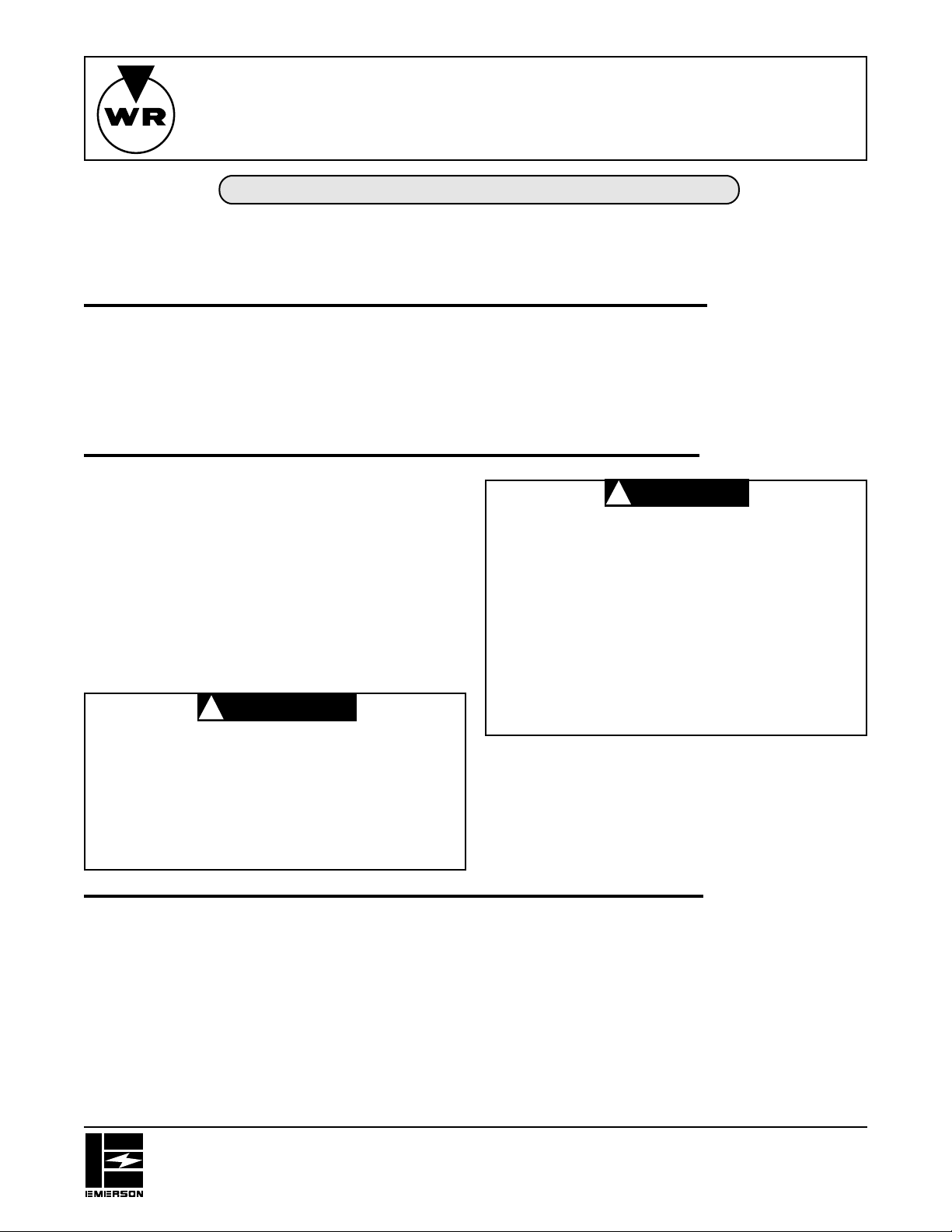
Wiring
All wiring must conform to local and national electrical codes and ordinances.
Connect in accordance with the wiring diagrams provided by the equipment manufacturer. If none are
provided, the following represents a typical installation.
CAUTION: Line voltage jumper is factory installed on
Jumper
Factory Installed
On Some Models
To Oil Burner
Control Or
Transformer Primary
Limit
Switch
Fan
Motor
Note:Make L1 “HOT” on
Optional Remote
Manual Switch
For Summer Fan
Fan
Switch
Line
120V installation
Diagram Using Limit In Line Voltage Circuit
L1
L2
some models. This jumper must be removed
when limit switch is used in low voltage or
millivolt circuit.
To Low Voltage
Or Millivolt
Burner Circuit
Fan
Motor
Limit
Switch
Fan
Switch
Note:Make L1 “HOT” on
120V installation
Diagram Using Limit In Low Voltage
or Millivolt Circuit
Optional Remote
Manual Switch
For Summer Fan
L1
Line
L2
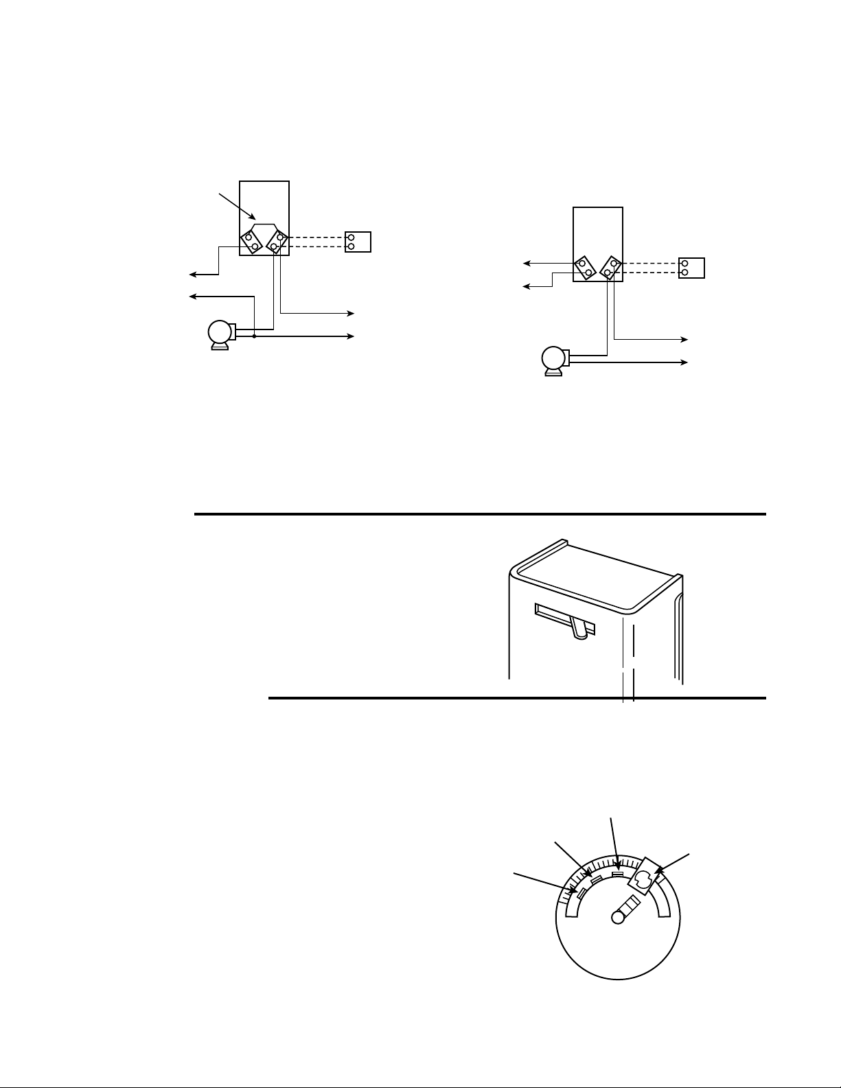
OPERATION
SUMMER FAN OPERATION
The cover does not have to be removed to access the
lever. To turn the fan on, slide the lever to the left “MAN”
position. To turn the fan off, slide the lever to the right
“AUTO” position.
For automatic operation of the fan during the heating or
cooling season, the lever must be in the “AUTO” position.
SETTING THE DIAL
To set pointers, hold dial securely with one hand and
move the pointers with the other hand. Do not force the
pointers past any stops on the dial even though the dial
may be graduated beyond the stops.
Limit
Move the right hand pointer so that its straight edge
indicates the temperature at which the contacts should
open. The limit pointer should never be set any higher
than the setting recommended by the furnace manufacturer.
Fan
Move the “Fan On” pointer so that its straight edge
indicates the temperature at which the fan contacts should
close to start the blower. Move the “Fan Off” pointer so that
its straight edge indicates the temperature at which the
fan contacts should open to stop the blower.
Left Hand
Pointer
(Fan Off)
MAN
Center
Pointer
(Fan On)
AUTO
Right Hand
Pointer
(Limit Opens)
0
0
2
2
0
5
5
0
1
0
0
1
0
5
FAN LIMIT
HOLD DIAL WHEN
CHANGING INDICATORS
DO NOT ADJUST
SAFETY STOP
3
0
0
Limit Stop
Page 3

INSTRUCTIONS D’INSTALLATION
WHITE-RODGERS
Opérateur : Il faut conserver ces instructions pour utilisation ultérieure !
IL FAUT LIRE ET SUIVRE SOIGNEUSEMENT TOUTES CES INSTRUCTIONS AVANT D’INSTALLER OU D’UTILISER CETTE COMMANDE POUR
ÉVITER DES BLESSURES ET/OU D’ENDOMMAGER L’ÉQUIPEMENT.
Cette commande de ventilateur et de limite combine, dans un
seul boîtier, un interrupteur de ventilateur avec une différence
réglable qui fait fonctionner le ventilateur dans un système à
air pulsé et un interrupteur de limite à différence fixe pour arrêter la chaudière si sa température dépasse une température
élevée spécifiée.
CETTE COMMANDE DOIT ÊTRE INSTALLÉE PAR UN
TECHNICIEN QUALIFIÉ.
Tous les branchements doivent être conformes aux codes
électriques et règlements locaux et nationaux.
Cette commande est un instrument de précision qui doit être
manipulée avec précaution. Une manutention maladroite ou
la déformation des composants peut causer un mauvais
fonctionnement des commandes.
Cette commande a été étalonnée avec précision à l’usine.
Toute tentative d’étalonnage de cette commande annule la
garantie de White-Rodgers.
A VERTISSEMENT
WARNING
!
Ne pas utiliser sur des circuits avec une tension
supérieure à celle spécifiée. Une tension plus élevée
peut endommager la commande et créer un risque
d’incendie.
En cas de doute de la tension de la ligne, la faire vérifier
par un technicien de chauffage et de climatisation ou
un électricien qualifié.
Commande de ventilateur et de limite
5D51-35, -78 et -90
DESCRIPTION
Un interrupteur de ventilation pour l’été est incorporé dans cette
commande pour fournir une méthode pratique d’utilisation
manuelle du ventilateur pour faire circuler l’air en été.
PRÉCAUTIONS
CAUTION
A TTENTION
!
Pour éviter les risques d’électrocution et/ou de dégâts
de l’équipement, il faut débrancher l’alimentation
électrique du système au fusible ou au coupe-circuit
principal jusqu’à la fin de l’intervention.
Lors d’une intervention, il faut identifier tous les fils
avant de les débrancher. Un mauvais branchement
peut causer un mauvais fonctionnement qui peut être
dangereux.
Après l’installation ou le remplacement, suivre les
instructions d’installation recommandées par le
fabricant de l’appareil pour assurer le bon
fonctionnement.
Dépose du couvercle
Pour enlever le couvercle, prendre fermement le haut et le bas
du couvercle et le tirer vers l’extérieur. Prendre le couvercle sur
les côtés rend la dépose plus difficile.
Emplacement
1. L’élément bimétallique ne doit pas être trop proche d’une
surface chaude de l’échangeur de chaleur. L’élément doit
toujours être au moins à 7,6 cm de toute surface chaude,
sauf si le fabricant de la chaudière a déterminé que l’emplacement est acceptable.
WHITE-RODGERS DIVISION
EMERSON ELECTRIC CO.
9797 REAVIS RD., ST. LOUIS, MO. 63123-5398
(314) 577-1300, TÉLÉCOPIEUR : (314) 577-1517
9999 HWY. 48, MARKHAM, ONT. L3P 3J3
(905) 475-4653, TÉLÉCOPIEUR : (905) 475-4625
Imprimé aux États-Unis
INSTALLATION
2. En cas de nouvelle application, consulter le fabricant de
l’équipement d’origine pour déterminer l’emplacement
approprié.
Montage encastré (surface verticale
ou inclinée)
1. Insérer le tube de l’élément dans le chapeau et monter le
boîtier de commande avec deux vis #10 (deux vis en
diagonale sont suffisantes).
2. Remettre en place le couvercle de la commande après
avoir fait le branchement et tous les réglages nécessaires.
No. DE PIÈCE 37-1558B
Remplace 37-1558-1
9714
Page 4

Branchements
Tous les branchements doivent être conformes aux codes et règlements électriques locaux et nationaux.
Brancher selon les schémas fournis par le fabricant de l’équipement. Si aucun n’est fourni, les schémas suivants
représentent une installation typique.
CAUTION: Line voltage jumper is factory installed on
Jumper
Cavalier installé en
Factory Installed
usine sur certains
On Some Models
modèles
I
nterrupteur
Vers la commande du
brûleur de mazout ou le
To Oil Burner
Control Or
Transformer Primary
primaire du
transformateur
Fan
Moteur du
Motor
ventilateur
Schéma pour utilisation de l’interrupteur de limite
Diagram Using Limit In Line Voltage Circuit
Limit
Switch
de limite
Remarque : Brancher L1 “SOUS TENSION”
Note:Make L1 “HOT” on
Interrupteur de
télécommande
Optional Remote
manuelle pour
ventilateur en été
For Summer Fan
Fan
Interrupteur
Switch
du
ventilateur
sur l’installation en 120 V
120V installation
dans le circuit de tension d’alimentation
Manual Switch
L1
Ligne
Line
L2
ATTENTION : Sur certains modèles, un cavalier de ligne
Vers le circuit de
basse tension ou
très basse tension
some models. This jumper must be removed
d’alimentation est installé en usine. Il faut enlever ce
when limit switch is used in low voltage or
cavalier quand l’interrupteur de limite est utilisé dans
millivolt circuit.
un circuit de basse tension ou très basse tension.
Optional Remote
Interrupteur de
Manual Switch
télécommande manuelle
For Summer Fan
pour ventilateur en été
To Low Voltage
Or Millivolt
Burner Circuit
du brûleur
Fan
Moteur du
Motor
ventilateur
Schéma pour utilisation de l’interrup-
Diagram Using Limit In Low Voltage
teur de limite dans un circuit de basse
tension ou de très basse tension
Limit
Interrupteur
Switch
de limite
Remarque : Brancher L1 “SOUS TENSION”
Fan
Interrupteur
Switch
du
ventilateur
Note:Make L1 “HOT” on
sur l’installation en 120 V
120V installation
or Millivolt Circuit
L1
L1
Ligne
Line
L2
L2
UTILISATION
UTILISATION DU VENTILATEUR EN ÉTÉ
Il n’est pas nécessaire d’enlever le couvercle pour obtenir accès
au levier. Pour mettre le ventilateur en marche, glisser le levier
vers la gauche, à la position manuelle “MAN.” Pour arrêter le
ventilateur, glisser le levier vers la droite, à la position automatique
“AUTO.”
Le levier doit être en position “AUTO” pour que le ventiateur
fonctionne automatiquement pendant la saison de chauffage ou
de climatisation.
RÉGLAGE DU CADRAN
Pour régler les repères, maintenir le cadran fermement en place
avec une main et déplacer les repères avec l’autre main. Ne pas
forcer les repères au-delà des butées du cadran, même s’il y a
des graduations sur le cadran au-delà des butées.
Limite
Déplacer le repère droit pour que son bord droit indique la température à laquelle les contacts doivent s’ouvrir. Il ne faut jamais régler le repère de limite à une température plus élevée
que la température recommandée par le fabricant de la chaudière.
Ventilateur
Déplacer le repère central de marche du ventilateur (Fan On)
pour que son bord droit indique la température à laquelle les
contacts du ventilateur se ferment pour mettre le ventilateur en
marche. Déplacer le repère gauche d’arrêt du ventilateur (Fan
Off) pour que son bord droit indique la température à laquelle les
contacts du ventilateur s’ouvrent pour arrêter le ventilateur.
Repère central
Repère
Left Hand
Pointer
gauche (arrêt
(Fan Off)
du ventilateur)
MAN
Center
Pointer
(Fan On)
(marche du
ventilateur)
AUTO
Repère droit
Right Hand
Pointer
(ouverture de
(Limit Opens)
limite)
0
0
2
2
0
5
5
0
1
0
0
1
0
5
VENTILATEUR LIMITE
FAN LIMIT
TENIR LE CADRAN PENDANT
HOLD DIAL WHEN
LE CHANGEMENT DES
CHANGING INDICATORS
REPÈRES. NE PAS
DO NOT ADJUST
RÉGLER LA LIMITE
SAFETY STOP
DE BUTÉE
3
0
0
Butée de
Limit Stop
limite
Page 5

5D51-35, -78 y -90
WHITE-RODGERS
Operador: ¡Guarde estas instrucciones para usarlas en el futuro!
SI NO SE LEEN Y SE SIGUEN TODAS LAS INSTRUCCIONES CUIDADOSAMENTE ANTES DE INSTALAR U OPERAR ESTE CONTROL SE PUEDEN
PRODUCIR LESIONES PERSONALES Y/O DAÑO A LA PROPIEDAD.
Control del Ventilador y del Limitador
INSTRUCCIONES DE INSTALACION
DESCRIPCION
Este control del ventilador y del limitador combina, en una caja,
un interruptor para el ventilador, con un diferencial ajustable que
opera el soplador en un horno de aire temperado forzado y un
interruptor limitador, con un diferencial fijo que cierra el quemador
automáticamente, si la temperatura del horno excede un punto
alto predeterminado.
ESTE CONTROL TIENE QUE SER INSTALADO POR UN
INSTALADOR CALIFICADO.
Todo el cableado tiene que cumplir con las regulaciones y los
códigos eléctricos nacionales y locales.
Este control es un instrumento de precisión y se tiene que
manejar cuidadosamente. Si el control se maneja torpemente o
si se distorsionan sus componentes puede funcionar mal.
Este control ha sido calibrado precisamente en la fábrica. Toda
acción para tratar de volverlo a calibrar anulará la garantía de
White-Rodgers.
ADVER TENCIA
WARNING
!
No lo use en circuitos que excedan los voltajes
especificados. Los voltajes más altos dañarán el control y pueden producir peligros de choque o incendio.
Si no sabe si su voltaje es de milivoltios o es bajo
voltaje o voltaje de línea, hágalo inspeccionar por un
contratista de calefacción y aire acondicionado
calificado o por un electricista con licencia.
Se ha incorporado en este control un interruptor para el ventilador
de verano, para ofrecer un método conveniente para operar
manualmente el ventilador para que el aire circule durante el
verano.
PRECAUCIONES
CAUTION
PRECA UCION
!
Para evitar el choque eléctrico y/o el daño en el equipo,
desconecte la energía eléctrica que va al sistema en el
fusible principal o en la caja de interruptores de circuito
hasta que se haya completado la instalación.
Marque todos los cables antes de la desconexión
cuando le haga el servicio a los controles. Los errores
en el cableado pueden producir una operación
incorrecta y peligrosa.
Después de la instalación o del cambio, siga las
instrucciones de instalación/servicio recomendadas
por el fabricante del artefacto para asegurarse que la
operación será la correcta.
Remoción de la Cubierta
Para remover la cubierta del control, agarre la cubierta en la
parte superior y la inferior y tírela hacia afuera. Si se agarra la
cubierta de los lados se dificultará la remoción.
Ubicación
1. El elemento bimetálico no debe quedar muy cerca de
ninguna superficie caliente del intercambiador de calor. El
elemento tiene que estar siempre por lo menos a 7,6 cm de
distancia de cualquier superficie caliente a menos que el
fabricante del horno haya determinado que la posición es
aceptable.
WHITE-RODGERS DIVISION
EMERSON ELECTRIC CO.
9797 REAVIS RD., ST. LOUIS, MO. 63123-5398
(314) 577-1300, FAX (314) 577-1517
9999 HWY. 48, MARKHAM, ONT. L3P 3J3
(905) 475-4653, FAX (905) 475-4625
Impreso en EE.UU.
INSTALACION
2. Si ésta es una aplicación nueva, haga el favor de consultar
con el fabricante del equipo original para verificar cuál es la
ubicación correcta.
Montaje al Ras (en Superficie Vertical
o Inclinada)
1. Inserte el tubo del elemento en el sombrerete y adjunte la
caja de control con tornillos # 10. (Dos tornillos, ubicados
diagonalmente, son suficientes.)
2. Vuelva a colocar la cubierta del control después del cableado
y haga cambios en los ajustes.
No. DE PARTE 37-1558B
Reemplaza a 37-1558-1
9714
Page 6

Cableado
Todo el cableado tiene que cumplir con las regulaciones y los códigos eléctricos nacionales y locales.
Conéctelo según los diagramas de cableado ofrecidos por el fabricante del equipo. Si no viene ninguno incluido, a
continuación se presenta una instalación típica.
CAUTION: Line voltage jumper is factory installed on
Jumper
Cable de empalme,
Factory Installed
instalado en la fábrica
On Some Models
en algunos modelos
Interruptor
To Oil Burner
Al control del que-
mador de aceite o al
Transformer Primary
Control Or
primario del
transformador
Fan
Motor del
Motor
ventilador
Diagrama que usa limitador en
Diagram Using Limit In Line Voltage Circuit
Limit
Switch
limitador
Nota: Haga L1 “CARGADO” en
Interruptor manual
Optional Remote
remoto opcional para
Manual Switch
el ventilador de
For Summer Fan
verano
Fan
Interruptor
Switch
del
ventilador
Note:Make L1 “HOT” on
la instalación de 120V
120V installation
el circuito de voltaje de línea
L1
L1
Line
Línea
L2
L2
PRECAUCION: El cable de empalme del voltaje de línea es
some models. This jumper must be removed
instalado en la fábrica en algunos modelos. Se
when limit switch is used in low voltage or
tiene que remover cuando el interruptor limitador
millivolt circuit.
se usa en un circuito de milivoltios o voltaje bajo.
Optional Remote
Interruptor manual remoto
opcional para el ventilador
For Summer Fan
Al circuito del
To Low Voltage
quemador de
Or Millivolt
voltaje bajo o
Burner Circuit
milivoltios
Fan
Motor del
Motor
ventilador
Diagrama que usa limitador en el
Diagram Using Limit In Low Voltage
circuito de milivoltios o voltaje bajo
Limit
Interruptor
Switch
limitador
Fan
Interruptor
Switch
ventilador
Nota: Haga L1 “CARGADO” en
Note:Make L1 “HOT” on
la instalación de 120V
120V installation
or Millivolt Circuit
del
Manual Switch
de verano
L1
L1
Línea
Line
L2
L2
OPERACION
OPERACION DEL VENTILADOR EN
EL VERANO
No se tiene que remover la cubierta para obtener acceso a la
palanca. Para encender el ventilador, deslice la palanca a la
izquierda a la posición “MAN”. Para apagar el ventilador, deslice
la palanca a la derecha a la posición “AUTO”.
Para que el ventilador opere automáticamente durante la estación
de calefacción o de enfriamiento, la palanca tiene que estar en
la posición “AUTO”.
AJUSTE DEL DIAL
Para ajustar los punteros, sujete el dial en forma segura con una
mano y mueva los punteros con la otra mano. No los fuerce
pasado ninguno de los topes en el dial, aun cuando éste pueda
tener graduación pasado los topes.
Limitador
Mueva el puntero del lado derecho de modo que su borde recto
indique la temperatura en la que se deben abrir los contactos.
El puntero limitador nunca debe ajustarse más alto que el ajuste
recomendado por el fabricante del horno.
Ventilador
Mueva el puntero de “Ventilador Encendido” (Fan On) de modo
que su borde recto indique la temperatura en la que se deben
cerrar los contactos del ventilador para hacer arrancar el soplador.
Mueva el puntero de “Ventilador Apagado” (Fan Off) de modo
que su borde recto indique la temperatura en la que los contactos
del ventilador se deben abrir para parar el soplador.
Puntero del
Left Hand
Pointer
lado izquierdo
(Fan Off)
(ventilador
apagado)
MAN
Puntero del
Center
centro
Pointer
(ventilador
(Fan On)
encendido)
AUTO
Right Hand
Puntero del lado
Pointer
derecho
(Limit Opens)
(limitador se abre)
0
0
2
2
0
5
5
0
1
0
0
1
0
5
FAN LIMIT
VENTILADOR
HOLD DIAL WHEN
SUJETE EL DIAL CUANDO
CAMBIE LOS INDICA-
CHANGING INDICATORS
DORES. NO AJUSTE
DO NOT ADJUST
LIMITADOR
EL TOPE DE
SAFETY STOP
SEGURIDAD
Limit Stop
Tope del
limitador
3
0
0
 Loading...