

Page 1
F61 Series
WHITE-RODGERS
Operator: Save these instructions for future use!
FAILURE TO READ AND FOLLOW ALL INSTRUCTIONS CAREFULLY
BEFORE INSTALLING OR OPERATING THIS CONTROL COULD CAUSE
PERSONAL INJURY AND/OR PROPERTY DAMAGE.
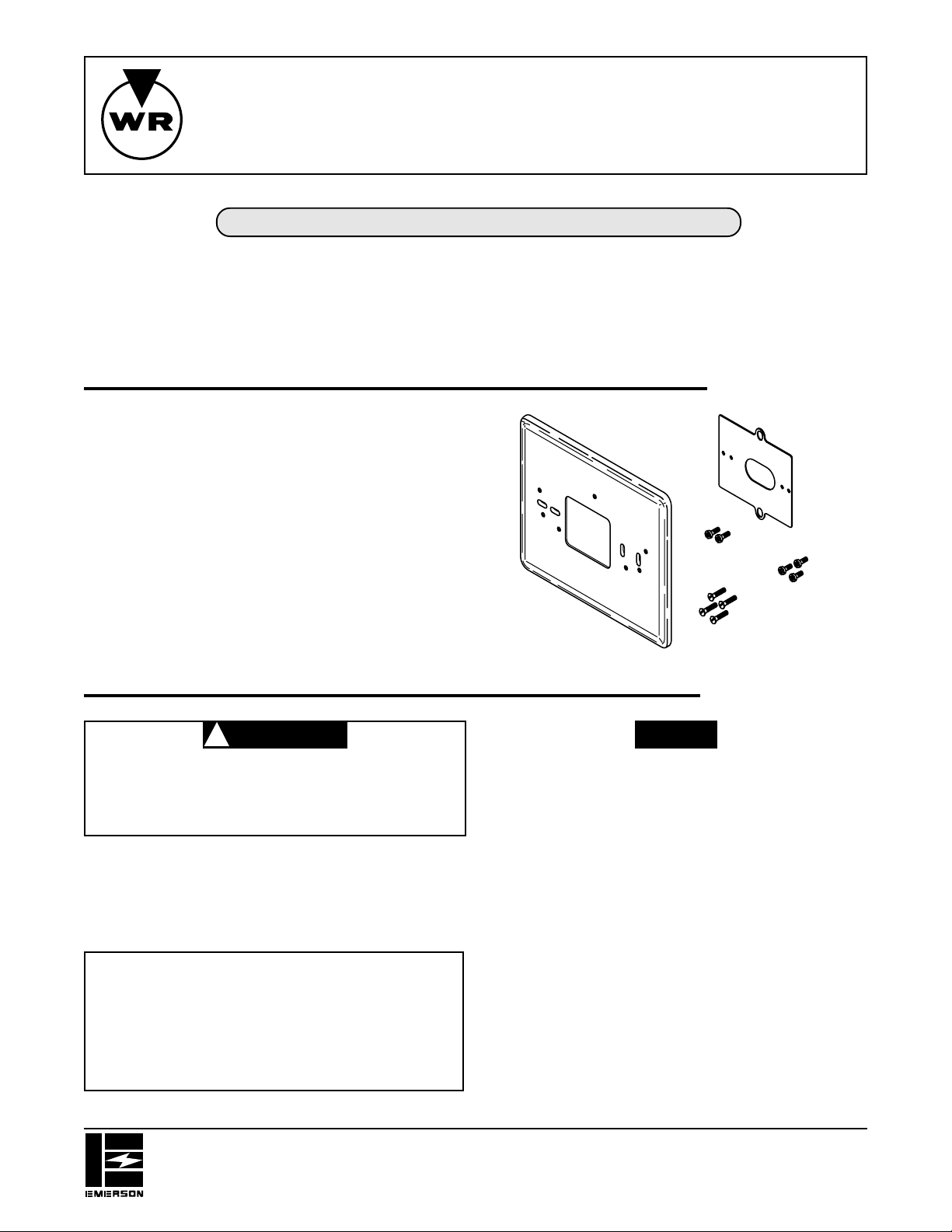
This adaptor plate assembly is designed for mounting a
1F6X, 1F7X, or 1F9X series thermostat to the wall or to a
junction box. The wall cover plate covers the junction box,
wall damage, or old thermostat markings. The adaptor
plate is designed to allow horizontal thermostat mounting,
regardless of junction box orientation.
All kits may not have adaptor plate or all screws shown.
Adaptor Plate Assembly
INST ALLA TION INSTRUCTIONS
DESCRIPTION
Adaptor Plate
5
No. 6 X
pan-head screw (2)
⁄
16
” Phillips
CAUTION
!
To prevent electrical shock and/or equipment damage, disconnect electrical power
at main fuse or circuit breaker until installation is complete.
CONTENTS
Description......................................................... 1
Precautions........................................................ 1
Installation.......................................................... 2
For 1F9X Digital Thermostats
For 1F7X Quartz Clock Thermostats
For 1F6X Thermostats
3
” Phillips
6-19 X
⁄
8
pan-head screw (3)
Wall Cover
Plate
3
⁄
” flat-head
6-32 X
4
machine screw (4)
PRECAUTIONS
NOTE
This instruction sheet is not intended as a wiring guide.
Refer to the thermostat installation instructions to ensure
proper wiring.
WHITE-RODGERS DIVISION
EMERSON ELECTRIC CO.
9797 REAVIS ROAD
ST. LOUIS, MISSOURI 63123-5398
Printed in U.S.A.
PART NO. 37-5148B
Replaces 37-5148A
9607
Page 2
INSTALLATION
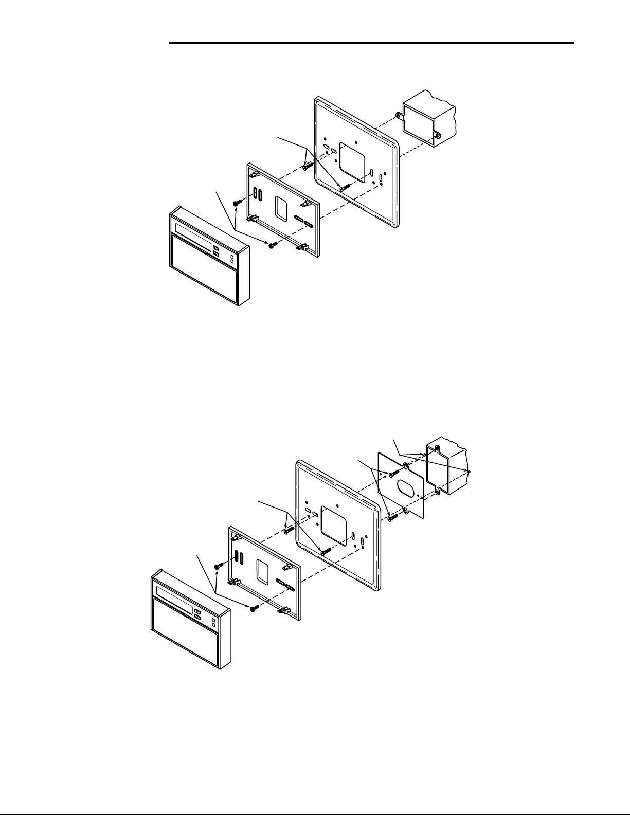
FOR 1F9X DIGIT AL THERMOSTATS
6-32 X 3⁄4” flat-head
machine screws
Junction Box
No. 6 X 5⁄16” Phillips
pan-head screws
Wall Cover Plate
Thermostat Subbase
(may have 2, 3, or
4 mounting holes)
Thermostat
Figure 1. Mounting 1F9X digital thermostat to horizontal junction box
Locate and drill two
clearance holes in wall
6-32 X 3⁄4” flat-head
machine screws
6-32 X 3⁄4” flat-head
machine screws
No. 6 X 5⁄16” Phillips
pan-head screws
Thermostat
Wall Cover Plate
Thermostat Subbase
(may have 2, 3, or
4 mounting holes)
Adaptor Plate
Figure 2. Mounting 1F9X digital thermostat to vertical junction box
Junction Box
2
Page 3
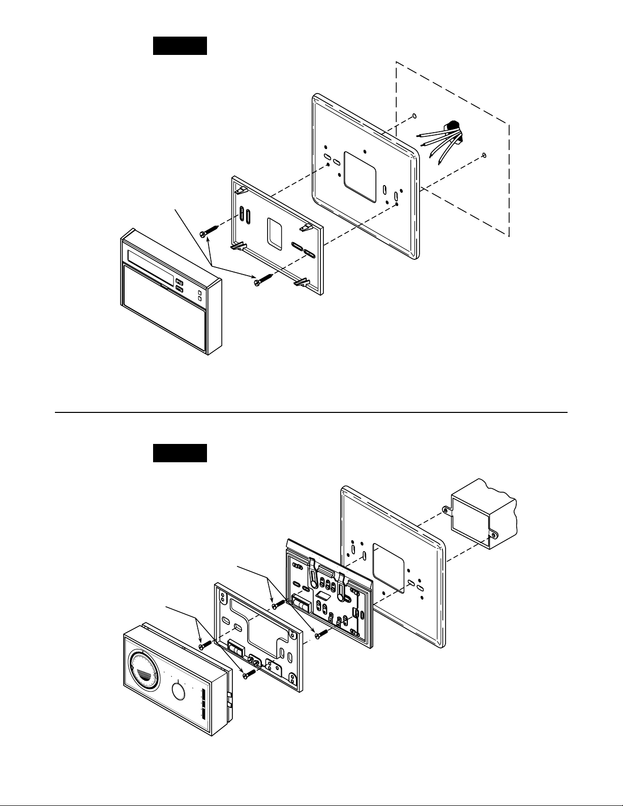
NOTE
When installing wall cover plate and thermostat directly to
wall, use the pointed screws supplied with the thermostat.
No. 6 X 1” pan-head screws
(supplied with thermostat)
Thermostat Subbase
Wall
Wall Cover Plate
Thermostat
Figure 3. Mounting 1F9X digital thermostat to wall
FOR 1F7X QUARTZ CLOCK THERMOSTATS
NOTE
Do not install the wall mounting plate and subbase at the
same time. The thermostat will not operate properly if both
wall mounting plate and subbase are installed.
6-32 X 3⁄4” flat-head
machine screws
6-32 X 3⁄4” flat-head
machine screws
FAN
ON
AUTO
SYSTEM
COOL HEAT
OFF
Junction Box
1
2
9
3
DAY
6
50 60 70 80 90
6
3
9
2
1
90
80
70
60
50
HI
LO
Wall Mounting
Plate*
Thermostat
Subbase*
*Do not use both subbase and wall
mounting plate – see note, above.
Wall Cover Plate
Thermostat
Figure 4. Mounting 1F7X quartz clock thermostat to horizontal junction box
3
Page 4

NOTE
Do not install the wall mounting plate and subbase at the
same time. The thermostat will not operate properly if both
wall mounting plate and subbase are installed.
FAN
ON
AUTO
6-32 X 3⁄4” flat-head
machine screws
6-32 X 3⁄4” flat-head
machine screws
6-32 X 3⁄4” flat-head
SYSTEM
COOL HEAT
OFF
clearance holes in wall
machine screws
Locate and drill two
Junction Box
Adaptor Plate
1
2
9
3
DAY
6
50 60 70 80 90
6
3
9
2
1
90
80
70
60
50
HI
LO
Wall Mounting
Plate*
Thermostat
Figure 5. Mounting 1F7X quartz clock thermostat to vertical junction box
NOTE
Do not install the wall mounting plate and subbase at the
same time. The thermostat will not operate properly if both
wall mounting plate and subbase are installed.
No. 6 X 1” pan-head screws
(supplied with thermostat)
Thermostat
Subbase*
*Do not use both subbase and wall
mounting plate – see note, above.
Wall Cover Plate
NOTE
When installing wall cover plate and thermostat directly to
wall, use the pointed screws supplied with the thermostat.
FAN
ON
AUTO
SYSTEM
COOL HEAT
OFF
No. 6 X 1” pan-head screws
(supplied with thermostat)
4
Wall
Thermostat
1
2
9
3
DAY
6
50 60 70 80 90
6
3
9
2
1
90
80
70
60
50
HI
LO
Wall Mounting
Plate*
Subbase*
*Do not use both subbase and wall
mounting plate – see note, above.
Wall Cover Plate
Thermostat
Figure 6. Mounting 1F7X quartz clock thermostat to wall
Page 5

FOR 1F6X THERMOST A TS
6-32 X 3⁄4” flat-head
machine screws
No. 6 X 3⁄8” Phillips
pan-head screws
Instructions Inside Cover
Thermostat
Thermostat Cover
Figure 7. Mounting 1F60 thermostat to horizontal junction box
Junction Box
Wall Cover Plate
No. 6 X 3⁄8” Phillips
pan-head screws
Thermostat Cover
Locate and drill two
clearance holes in wall
6-32 X 3⁄4” flat-head
machine screws
6-32 X 3⁄4” flat-head
machine screws
Adaptor Plate
TIME
SET
SET
BACK
COOL OFF HEAT
0 3 6 9°C
0 5 10 15°F
AUTO CONT.
FAN
Wall Cover Plate
Thermostat
Figure 8. Mounting 1F60 thermostat to vertical junction box
Junction Box
5
Page 6

NOTE
When installing wall cover plate and thermostat directly to
wall, use the pointed screws supplied with the thermostat.
No. 6 X 1” pan-head screws
(supplied with thermostat)
No. 6 X 3⁄8” Phillips
pan-head screws
AM
PM
SETBACK
Instructions Inside Cover
HEAT
COOL
WHITE-RODGERS
50 60 70 80 90
°F
10 21 32 °C
Thermostat Cover
TIME
SET
SET
BACK
COOL OFF HEAT
0 3 6 9
0 5 10 15
°C
°F
AUTO CONT.
FAN
Thermostat
Figure 9. Mounting 1F60 thermostat to wall
Wall
Wall Cover Plate
AM
PM
SETBACK
Instructions Inside Cover
HEAT
COOL
WHITE-RODGERS
CLEAR
SET
BACK
TIME
SET
COMPRESSOR
MALFUNCTION
EMERGENCY
HEAT
AUXILIARY
HEAT
60
65
70 21
55
10 50
75
80
85
90 32
°F °C
Thermostat Cover
6-32 X 3⁄4” flat-head
machine screws
No. 6 X 3⁄8” Phillips
pan-head screws
Wall Cover Plate
COOL OFF HEAT EMHT
0 3 6 9°C
0 5 10 15°F
AUTO CONT.
FAN
Thermostat Subbase
Thermostat
(connect harness –
snap onto subbase)
Figure 10. Mounting 1F62 thermostat to horizontal junction box
Junction Box
6
Page 7

6-32 X 3⁄4” flat-head
machine screws
Locate and drill two
clearance holes in wall
AM
PM
SETBACK
Instructions Inside Cover
HEAT
COOL
WHITE-RODGERS
CLEAR
SET
BACK
TIME
SET
COMPRESSOR
MALFUNCTION
EMERGENCY
HEAT
AUXILIARY
HEAT
60
65
70 21
55
75
10 50
80
85
90 32
°F °C
Thermostat Cover
6-32 X 3⁄4” flat-head
machine screws
3
⁄8” Phillips
No. 6 X
pan-head screws
Wall Cover Plate
COOL OFF HEAT EMHT
0 3 6 9°C
0 5 10 15°F
AUTO CONT.
FAN
Thermostat
Subbase
Thermostat
(connect harness –
snap onto subbase)
Figure 11. Mounting 1F62 thermostat to vertical junction box
NOTE
Junction Box
Adaptor Plate
When installing wall cover plate and thermostat directly to
wall, use the pointed screws supplied with the thermostat.
No. 6 X 1” pan-head screws
(supplied with thermostat)
No. 6 X 3⁄8” Phillips
pan-head screws
CLEAR
10 50
SET
BACK
TIME
SET
COOL OFF HEAT EMHT
0 3 6 9°C
0 5 10 15°F
AUTO CONT.
FAN
60
65
70 21
55
75
80
85
90 32
°F °C
Thermostat
(connect harness –
snap onto subbase)
AM
PM
SETBACK
Instructions Inside Cover
HEAT
COOL
WHITE-RODGERS
COMPRESSOR
MALFUNCTION
EMERGENCY
HEAT
AUXILIARY
HEAT
Wall
Wall Cover Plate
Thermostat
Subbase
Thermostat Cover
Figure 12. Mounting 1F62 thermostat to wall
7
Page 8

If you need further information about this product, please write to
White-Rodgers Division, Emerson Electric Co.
9797 Reavis Road
St. Louis, MO 63123-5398
Attention: Technical Service Department
 Loading...