

Page 1
Hot Water Controls
WHITE-RODGERS
Operator: Save these instructions for future use!
FAILURE TO READ AND FOLLOW ALL INSTRUCTIONS CAREFULLY
BEFORE INSTALLING OR OPERATING THIS CONTROL COULD CAUSE
PERSONAL INJURY AND/OR PROPERTY DAMAGE.
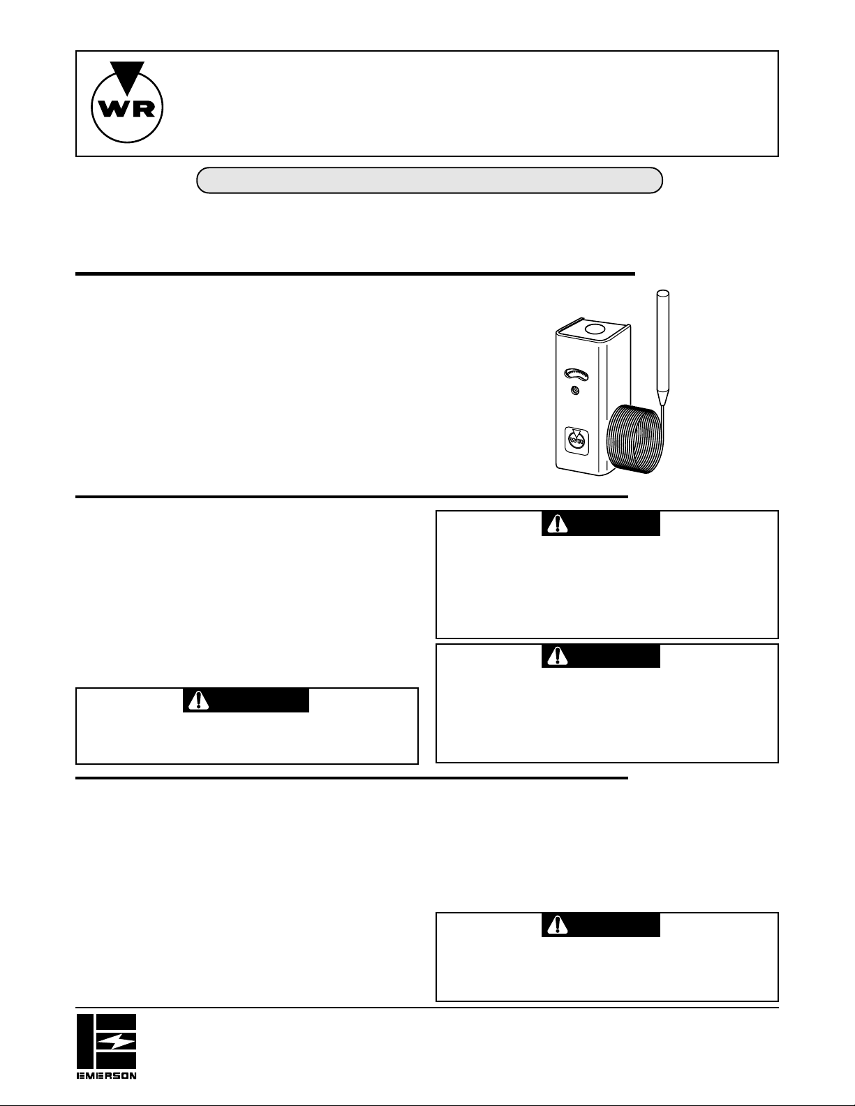
These hot water controls were designed for use on hot water
heating installations but they may be used on other heating
applications to control the temperature of other fluids. The fluid
they are to be used with must not be corrosive to copper.
These controls have capillary tubing between the temperature
sensitive bulb and the switch mechanism so that the switch
mechanism can be mounted at any convenient location while
the temperature sensitive bulb is located in the fluid to be
controlled.
These controls have special contacts which are suitable for use
on low voltage and millivolt (thermocouple generator type)
circuits as well as line voltage equipment such as gas valves, oil
burner motors, etc.
THESE CONTROLS MUST BE INSTALLED BY A QUALIFIED
INSTALLER
Do not exceed the specification ratings.
All wiring must conform to local and national electrical codes and
ordinances.
This control is a precision instrument, and should be handled
carefully. Rough handling or distorting components could cause
the control to malfunction.
This control has been accurately calibrated at the factory. any
attempt to calibrate this control will void the White-Rodgers
warranty.
WARNING
Do not use on circuits exceeding specified voltage.
Higher voltage will damage control and could cause
shock or fire hazard.
Remote T ype
INSTALLATION INSTRUCTIONS
DESCRIPTION
PRECAUTIONS
CAUTION
Label all wires prior to disconnection when servicing
controls. Wiring errors can cause improper and dangerous operation.
Following installation or replacement, follow appliance
manufacturer's recommended installation and/or service instructions to insure proper operation.
CAUTION
To prevent electrical shock and/or equipment damage,
disconnect electric power to system at main fuse or
circuit breaker box until installation is complete.
Shut off main gas to heating system until installation is
complete.
If the equipment manufacturer recommends a control location,
follow such recommendations. If none is offered, the following
recommendations should be observed.
When used to control the temperature of a vat or tank, locate the
control bulb in a place representative of the average temperature. Make certain that the fluid being controlled is not injurious
to the copper element.
When used for high limit service on a heating boiler, the control
should be installed in the riser close to the boiler, or in a boiler
tapping that is near the top or hottest section of the boiler. If the
boiler is also used to heat domestic hot water, make sure that the
high limit control is not in that section of the boiler that contains
the heat exchanger or piping for domestic hot water.
WHITE-RODGERS DIVISION
EMERSON ELECTRIC CO.
9797 REAVIS RD., ST. LOUIS, MO. 63123
(314) 577-1300, FAX (314) 577-1517
9999 HWY. 48, MARKHAM, ONT. L3P 3J3
(905) 475-4653, FAX (905) 475-4625
Printed in U.S.A.
INSTALLATION
When used for low limit or operator service, the control should
be located near that section of the boiler that contains the heat
exchanger or piping for domestic hot water.
Be careful to avoid damage to the capillary tubing between the
control and the temperature sensitive bulb. This tubing should
be led over a path that will protect it from cuts, blows, wear due
to vibration, etc.
CAUTION
Do not dent or bend the bulb as this will change the
control calibration and cause it to cycle at a temperature lower than the dial setting.
PART NO. 37-0882C
Replaces 37-0882B & 37-9025
9546
Page 2
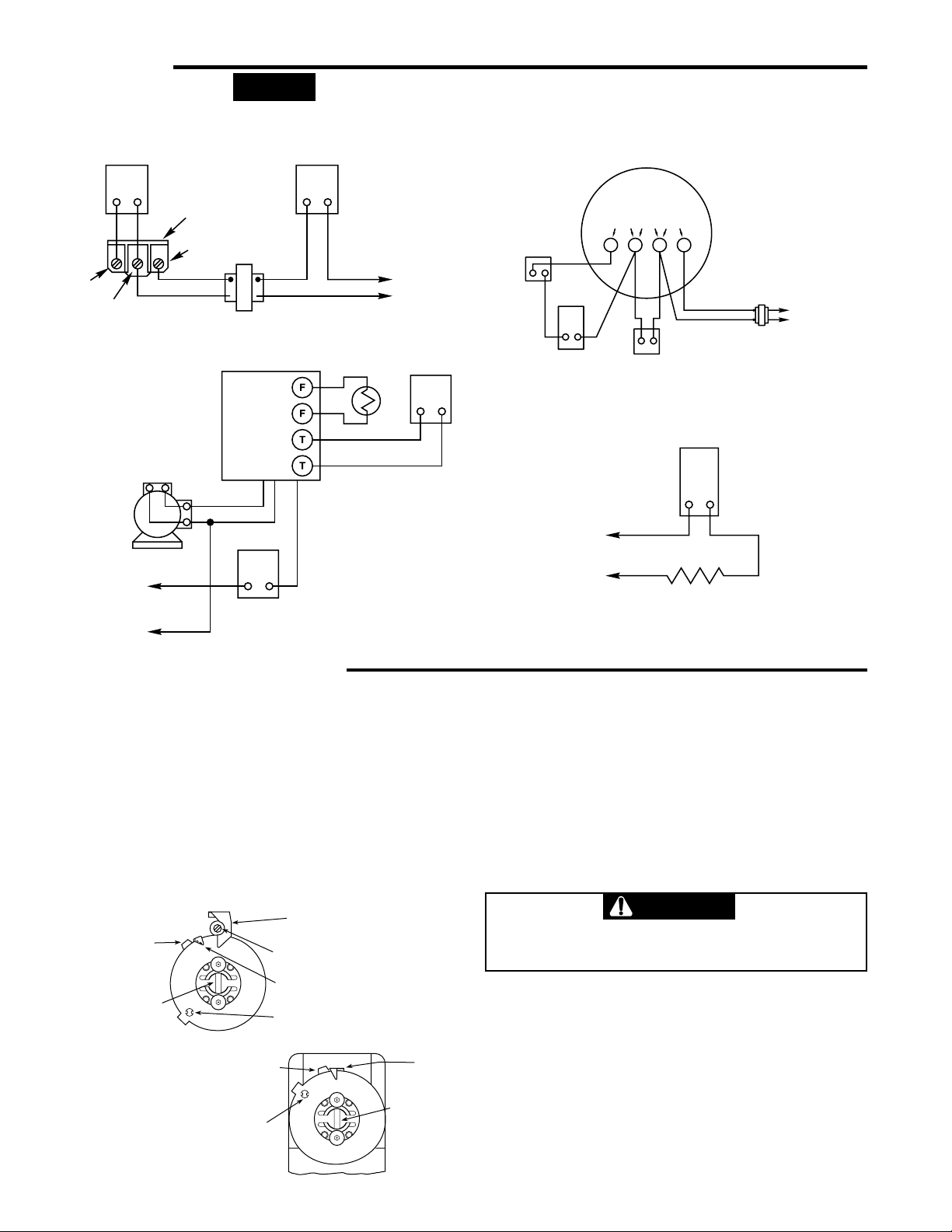
WIRING
NOTE
All wiring should be done according to local and national
electrical codes.
THERMOSTAT HIGH LIMIT
GAS VALVE
TERMINAL PANEL
TR
TH
TH-TR
24VAC
TRANSFORMER
Used as high
limit control with
36C03 Type Gas
Valve
HOT
LINE
N
If the boiler or burner manufacturer recommends a wiring
diagram, then follow such recommendations.
If none is offered, these diagrams show suggested circuits.
DIAPHRAGM
THERMOSTAT
GAS VALVE
THERM PILOT TRANS
1234
Used as high limit
control with
diaphragm gas valve
TRANSFORMER
TO
LINE
TYPE 668
HOT
N
IGNITION
TRANSF.
BURNER
MOTOR
LINE
OIL BURNER CONTROL
ORANGE
WHITE
LIMIT
CONTROL
Used as high
limit control with
BLACK
oil burner control
THERMOSTAT
SETTING THE CONTROL
CONTROLS WITH ADJUSTABLE DIFFERENTIAL
The movable indicator points to the temperature at which the
contacts open. The fixed indicator points to the temperature at
which the contacts close. The difference between these two
indicators is the differential.
To set the control:
1. Use a screwdriver in the adjusting slot (A) on the front of the
control to turn the dial so that the fixed indicator (B) points
to the temperature at which the contacts will close.
2. Turn the differential adjusting screw (C) until the movable
indicator (D) points to the temperature at which the contacts
will open.
“F” Stop tab
“A” Adjusting
slot
ADJUSTABLE DIFFERENTIAL
“F” Stop tab
“B” Fixed indicator
(cut-in point)
“C” Differential adjusting
screw
“D” Movable indicator
(cut-out point)
“E” Stop screw
“B” Fixed
indicator
LIMIT
CONTROL
AUTOMATIC
IF AUTOMATIC PILOT IS NOT USED,
CONNECT A JUMPER BETWEEN
PILOT
THE PILOT TERMINALS
Used as operating control
for electrically heated tank
TYPE
230-19
TEMPERATURE
CONTROL
HOT
LINE
N
LOAD
CONTROLS WITH A FIXED DIFFERENTIAL
The indicator (B) points to the temperature at which the contacts
open.
To set the control:
Use a screwdriver in the adjusting slot (A) on the front of the
control to rotate dial until the desired temperature at which
the contacts will open is positioned directly under the
indicator (B).
CONTROLS WITH ADJUSTABLE STOPS
CAUTION
Setting stop higher than control being replaced could
cause personal injury and/or property damage.
1. Loosen stop screw (E) with enclosed wrench.
2. Set dial to original equipment manufacturer's specification.
3. Without moving the dial, move stop tab (F) against indicator.
4. Retighten stop screw (E).
“E” Stop screw
“A” Adjusting
FIXED DIFFERENTIAL
slot
2
Page 3

WHITE-RODGERS
Utilisateur: conservez ces instructions pour vous y référer au besoin!
SI VOUS NE LISEZ PAS ATTENTIVEMENT CES INSTRUCTIONS AVANT
D’INSTALLER ET D’UTILISER LA COMMANDE, VOUS RISQUEZ DE CAUSER
DES BLESSURES ET DES DOMMAGES MATÉRIELS.
Ces commandes ont été conçues pour servir avec des systèmes
de chauffage à eau chaude. Elles peuvent cependant servir à
d’autres applications de régulation de température d’un liquide.
Ce liquide ne doit pas corroder le cuivre.
Les commandes sont dotées d’un tube capillaire qui relie le
capteur thermosensible au commutateur. Celui-ci peut ainsi
être installé dans un endroit pratique alors que le capteur baigne
dans le liquide dont la température doit être contrôlée.
Les commandes sont dotées de bornes spéciales qui permetent
de les utiliser avec des circuits à basse tension et à millivolts
(avec générateur à thermocouple) ainsi qu’avec des équipements
à la tension du réseau, comme des robinets à gaz, des moteurs
de brûleurs à mazout, etc.
LA PRÉSENTE COMMANDE DOIT ÊTRE INSTALLÉE PAR
UN TECHNICIEN QUALIFIÉ.
Ne dépassez pas les charges nominales.
Tout le câblage doit être conforme aux codes et règlements
locaux et nationaux qui régissent les installations électriques.
Cette commande est un instrument de précision qui doit être
manipulé avec soin. Elle peut se détraquer si elle est manipulée
de façon négligente ou si des composantes sont déformées.
La commande a été calibrée avec précision lors de la fabrication.
Toute tentative de calibrer l’appareil annulera la garantie de
White-Rodgers.
AVERTISSEMENT
N’installez pas cet appareil sur des circuits qui dépassent la tension nominale. Une tension trop élevée peut
endommager la commande et poser des risques de
chocs électriques et d’incendie.
Commande d’eau chaude
AVEC CAPTEUR À DISTANCE
INSTRUCTIONS D’INSTALLATION
DESCRIPTION
PRÉCAUTIONS
ATTENTION
Prenez soin d’identifier les fils avant de débrancher ou
de réviser la commande. Les erreurs de raccordement
peuvent entraîner un fonctionnement incorrect ou
dangereux de la commande.
Pour assurer le bon fonctionnement de la commande
après l’avoir installée, suivre les directives d’installation ou de révision du fabricant de l’équipement.
ATTENTION
Afin de prévenir les chocs électriques et les dommages
matériels pendant l’installation, coupez l’alimentation
électrique au panneau de distribution principal.
Coupez le gaz qui alimente le système de chauffage
pendant toute la durée de l’installation.
Si un emplacement de la commande est recommandé par le
fabricant de l’équipement, alors veuillez vous y conformer. Si
aucun emplacement n’est suggéré, veuillez suivre les conseils
suivants.
Si la commande est utilisée pour contrôler la température d’un
bassin ou d’un réservoir, alors placer le capteur là où la température du liquide correspond à la moyenne. S’assurer que le
liquide à contrôler ne cause aucun dommage au cuivre.
Si la commande est utilisée comme limiteur à maximum sur une
chaudière de chauffage, elle doit être installée près de celle-ci,
sur la colonne montante, ou dans une ouverture taraudée qui est
située dans la partie supérieure ou dans la section la plus
chaude. Si la chaudière sert aussi pour l’eau chaude domestique,
s’assurer que le limiteur à maximum n’est pas installé dans la
partie de la chaudière où se trouvent l’échangeur de chaleur ou
les canalisations d’eau chaude domestique.
WHITE-RODGERS DIVISION
EMERSON ELECTRIC CO.
9797 REAVIS RD., ST. LOUIS, MO. 63123
(314) 577-1300, Télécopieur (314) 577-1517
9999 HWY. 48, MARKHAM, ONT. L3P 3J3
(905) 475-4653, Télécopieur (905) 475-4625
Imprimé aux É.-U.A.
INST ALLATION
Si la commande sert de limiteur à minimum ou d’actionneur, elle
doit alors être installée dans la partie de la chaudière où se
trouvent l’échangeur de chaleur ou les canalisations d’eau
chaude domestique.
Prendre soin de ne pas endommager le tube capillaire qui relie
la commande et le capteur thermosensible. Acheminer ce tube
de façon à ce qu’il soit protégé contre les coupures, les coups,
l’usure due aux vibrations, etc.
ATTENTION
Ne pas plier ou bosser le capteur, car l’étalonnage en
serait alors modifié, entraînant la mise en marche de
l’équipement à une température inférieure au point de
consigne.
PIÈCE No 37-0882C
Remplace 37-0882B & 37-9025
9546
Page 4

CÂBLAGE
NOTE
Tout le câblage doit être conforme aux codes et règlements
locaux et nationaux qui régissent les installations électriques.
THERMOSTAT
TH
TH-TR
TRANSFORMATEUR
D’ALLUMAGE
SOUS TENSION
MOTEUR DE
BRÛLEUR
SECTEUR
N
ORNIER DU
ROBINET À GAZ
TR
24VAC
TRANSFORMATEUR
COMMANDE DE BRÛLEUR
ORANGE
BLANC
LIMITEUR À MAXIMUM
À MAZOUT
LIMITEUR
Utilisée comme
limiteur à
maximum avec
robinet à gaz
Type 36C03
THERMOSTAT
Utilisée comme
limiteur à maximum
avec commande de
NOIR
brûleur à mazout
SOUS TENSION
SECTEUR
N
Si le fabricant de la chaudière ou du brûleur recommande un
schéma de câblage, alors veuillez vous y référer.
Dans le cas contraire, voici quelques schémas de circuits
recommandés.
ROBINET À GAZ
DIAPHRAGM
À MEMBRANE
THERMOSTAT
LIMITEUR
CONTROL
LIMIT
SOUS
TENSION
RÉSEAU
GAS VALVE
THERM PILOT TRANS
1234
VEILLEUSE
AUTOMATIC
AUTOMATIQUE
PILOT
N
Utilisée comme limiteur
Used as high limit
à maximum avec robinet
control with
à gaz à membrane
diaphragm gas valve
TRANSFORMATEUR
TRANSFORMER
SI UNE VEILLEUSE AUTOMATIQUE N’EST PAS
IF AUTOMATIC PILOT IS NOT USED,
CONNECT A JUMPER BETWEEN
UTILISÉE, RACCORDER LES DEUX BORNES DE
THE PILOT TERMINALS
LA VEILLEUSE À L’AIDE D’UN CAVALIER.
RÉGULATEUR DE
TEMPÉRATURE
CHARGE
TO
SECTEUR
LINE
TYPE 230-19
COMMANDES À DIFFÉRENTIEL RÉGLABLE
L’indicateur mobile donne la température à laquelle les contacts
seront ouverts. L’indicateur fixe donne la température à laquelle
les contacts seront fermés. La différence entre les deux indicateurs représente le différentiel.
Pour régler la commande :
1. Introduire la pointe d’un tournevis dans la fente de réglage
(A) qui se trouve à l’avant de la commande. Tourner le
cadran pour que l’indicateur fixe (B) indique la température
à laquelle les contacts devront être fermés.
2. Tourner la vis de réglage du différentiel (C) jusqu’à ce que
l’indicateur mobile (D) indique la température à laquelle les
contacts devront être ouverts.
B INDICATEUR FIXE
F BUTÉE
A FENTE DE
RÉGLAGE
(POINT D’ENCLENCHEMENT)
C VIS DE RÉGLAGE
DU DIFFÉRENTIEL
D INDICATEUR MOBILE
(POINT DE
DÉCLENCHEMENT)
E VIS DE
BUTÉE
DIFFÉRENTIEL RÉGLABLE
F BUTÉE
E VIS DE
BUTÉE
B INDICATEUR FIXE
(POINT D’ENCLENCHEMENT)
A FENTE DE
RÉGLAGE
RÉGLAGE DE LA COMMANDE
COMMANDES À DIFFÉRENTIEL FIXE
L’indicateur (B) donne la température à laquelle les contacts
seront ouverts.
Pour régler la commande :
Introduire la pointe d’un tournevis dans la fente de réglage
(A) qui se trouve à l’avant de la commande. Tourner le cadran
pour que la température à laquelle les contacts devront être
ouverts se trouve directement sous l’indicateur (B).
COMMANDES À BUTÉES RÉGLABLES
ATTENTION
Il y a un risque de blessures et de dommages matériels
si la butée est réglée à un point de consigne plus élevé
que celle de la commande qui est remplacée.
1. Desserrer la vis de butée (E) à l’aide de la clé fournie.
2. Régler le cadran selon les recommandations du fabricant de
l’équipement.
3. En prenant soin de ne pas déplacer le cadran, accoter la
butée (F) contre l’indicateur.
4. Serrer à nouveau la vis de butée (E).
DIFFÉRENTIEL FIXE
2
 Loading...